EP2006648A9 - Rotation angle detector - Google Patents
Rotation angle detector Download PDFInfo
- Publication number
- EP2006648A9 EP2006648A9 EP07741241A EP07741241A EP2006648A9 EP 2006648 A9 EP2006648 A9 EP 2006648A9 EP 07741241 A EP07741241 A EP 07741241A EP 07741241 A EP07741241 A EP 07741241A EP 2006648 A9 EP2006648 A9 EP 2006648A9
- Authority
- EP
- European Patent Office
- Prior art keywords
- rotation angle
- rotatable body
- sensing portion
- rotation
- rotatable
- Prior art date
- Legal status (The legal status is an assumption and is not a legal conclusion. Google has not performed a legal analysis and makes no representation as to the accuracy of the status listed.)
- Withdrawn
Links
Images


Classifications
-
- G—PHYSICS
- G01—MEASURING; TESTING
- G01L—MEASURING FORCE, STRESS, TORQUE, WORK, MECHANICAL POWER, MECHANICAL EFFICIENCY, OR FLUID PRESSURE
- G01L5/00—Apparatus for, or methods of, measuring force, work, mechanical power, or torque, specially adapted for specific purposes
- G01L5/22—Apparatus for, or methods of, measuring force, work, mechanical power, or torque, specially adapted for specific purposes for measuring the force applied to control members, e.g. control members of vehicles, triggers
- G01L5/221—Apparatus for, or methods of, measuring force, work, mechanical power, or torque, specially adapted for specific purposes for measuring the force applied to control members, e.g. control members of vehicles, triggers to steering wheels, e.g. for power assisted steering
-
- G—PHYSICS
- G01—MEASURING; TESTING
- G01D—MEASURING NOT SPECIALLY ADAPTED FOR A SPECIFIC VARIABLE; ARRANGEMENTS FOR MEASURING TWO OR MORE VARIABLES NOT COVERED IN A SINGLE OTHER SUBCLASS; TARIFF METERING APPARATUS; MEASURING OR TESTING NOT OTHERWISE PROVIDED FOR
- G01D5/00—Mechanical means for transferring the output of a sensing member; Means for converting the output of a sensing member to another variable where the form or nature of the sensing member does not constrain the means for converting; Transducers not specially adapted for a specific variable
- G01D5/12—Mechanical means for transferring the output of a sensing member; Means for converting the output of a sensing member to another variable where the form or nature of the sensing member does not constrain the means for converting; Transducers not specially adapted for a specific variable using electric or magnetic means
- G01D5/14—Mechanical means for transferring the output of a sensing member; Means for converting the output of a sensing member to another variable where the form or nature of the sensing member does not constrain the means for converting; Transducers not specially adapted for a specific variable using electric or magnetic means influencing the magnitude of a current or voltage
- G01D5/20—Mechanical means for transferring the output of a sensing member; Means for converting the output of a sensing member to another variable where the form or nature of the sensing member does not constrain the means for converting; Transducers not specially adapted for a specific variable using electric or magnetic means influencing the magnitude of a current or voltage by varying inductance, e.g. by a movable armature
- G01D5/204—Mechanical means for transferring the output of a sensing member; Means for converting the output of a sensing member to another variable where the form or nature of the sensing member does not constrain the means for converting; Transducers not specially adapted for a specific variable using electric or magnetic means influencing the magnitude of a current or voltage by varying inductance, e.g. by a movable armature by influencing the mutual induction between two or more coils
- G01D5/2086—Mechanical means for transferring the output of a sensing member; Means for converting the output of a sensing member to another variable where the form or nature of the sensing member does not constrain the means for converting; Transducers not specially adapted for a specific variable using electric or magnetic means influencing the magnitude of a current or voltage by varying inductance, e.g. by a movable armature by influencing the mutual induction between two or more coils by movement of two or more coils with respect to two or more other coils
- G01D5/2093—Mechanical means for transferring the output of a sensing member; Means for converting the output of a sensing member to another variable where the form or nature of the sensing member does not constrain the means for converting; Transducers not specially adapted for a specific variable using electric or magnetic means influencing the magnitude of a current or voltage by varying inductance, e.g. by a movable armature by influencing the mutual induction between two or more coils by movement of two or more coils with respect to two or more other coils using polyphase currents
-
- G—PHYSICS
- G01—MEASURING; TESTING
- G01L—MEASURING FORCE, STRESS, TORQUE, WORK, MECHANICAL POWER, MECHANICAL EFFICIENCY, OR FLUID PRESSURE
- G01L3/00—Measuring torque, work, mechanical power, or mechanical efficiency, in general
- G01L3/02—Rotary-transmission dynamometers
- G01L3/04—Rotary-transmission dynamometers wherein the torque-transmitting element comprises a torsionally-flexible shaft
- G01L3/10—Rotary-transmission dynamometers wherein the torque-transmitting element comprises a torsionally-flexible shaft involving electric or magnetic means for indicating
- G01L3/101—Rotary-transmission dynamometers wherein the torque-transmitting element comprises a torsionally-flexible shaft involving electric or magnetic means for indicating involving magnetic or electromagnetic means
- G01L3/104—Rotary-transmission dynamometers wherein the torque-transmitting element comprises a torsionally-flexible shaft involving electric or magnetic means for indicating involving magnetic or electromagnetic means involving permanent magnets
-
- G—PHYSICS
- G01—MEASURING; TESTING
- G01L—MEASURING FORCE, STRESS, TORQUE, WORK, MECHANICAL POWER, MECHANICAL EFFICIENCY, OR FLUID PRESSURE
- G01L3/00—Measuring torque, work, mechanical power, or mechanical efficiency, in general
- G01L3/02—Rotary-transmission dynamometers
- G01L3/04—Rotary-transmission dynamometers wherein the torque-transmitting element comprises a torsionally-flexible shaft
- G01L3/10—Rotary-transmission dynamometers wherein the torque-transmitting element comprises a torsionally-flexible shaft involving electric or magnetic means for indicating
- G01L3/101—Rotary-transmission dynamometers wherein the torque-transmitting element comprises a torsionally-flexible shaft involving electric or magnetic means for indicating involving magnetic or electromagnetic means
- G01L3/105—Rotary-transmission dynamometers wherein the torque-transmitting element comprises a torsionally-flexible shaft involving electric or magnetic means for indicating involving magnetic or electromagnetic means involving inductive means
Landscapes
- Physics & Mathematics (AREA)
- General Physics & Mathematics (AREA)
- Electromagnetism (AREA)
- Measurement Of Length, Angles, Or The Like Using Electric Or Magnetic Means (AREA)
- Power Steering Mechanism (AREA)
Abstract
Description
- The present invention relates to a rotation angle sensor used in a vehicle body control system of a vehicle, for instance, and in particular to a rotation angle sensor for a multi-turn steering wheel of a power steering system of a vehicle, for instance.
- Cited below are examples of rotation angle sensors used in a vehicle body control system of a vehicle or the like.
- There exist a method and a device for measuring angle of a rotatable body as disclosed in
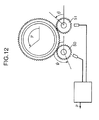
Patent Document 1, for instance. This is an example of a sensor for detecting rotation angle of a rotatable body, such as an automotive steering wheel, which rotates within a limited but over single-turn range. The device shown inFIG. 12 disclosed inPatent Document 1 detects the rotation angle from angles of rotation of tworotatable bodies - Also, as an example, a below-described rotation angle sensor is disclosed in
Patent Document 2. Referring toFIG. 13 , the rotation angle sensor disclosed inPatent Document 2 is such that twogear portions 259 are attached to a rotary shaft (not shown) of which rotation angle is to be detected via a hookingspring 260. These twogear portions 259 are engaged withgear portions 262 which holdcode disks 261 having outer peripheral surfaces on which different magnetic poles are alternately arranged. As the magnetic poles provided on thecode disks 261 move in rotary motion as a result of rotation of the rotary shaft of which rotation angle is to be detected, it is possible to detect the rotation angle of the rotary shaft by counting displacements of the magnetic poles by means ofmagnetism sensing devices 263 which are disposed face to face with the outer peripheral surfaces of thecode disks 261. - With this rotation angle sensor attached to two shafts which are interconnected by a torsion bar, for example, it is possible to detect torque by comparing rotation angles of the rotary shafts when the torque acts between the two shafts and torsion occurs between the shafts.
- A manufacturing process of the rotation angle sensor of
FIG. 13 includes a magnet forming step for magnetizing the magnetic poles of thecode disks 261 and an mounting step for mounting thegear portions 262 in such a way that thegear portions 262 mesh with thegear portions 259. Generally, the magnetic poles of thecode disks 261 are formed by setting thegear portions 262 to which theunmagnetized code disks 261 have been attached in a magnetizer and magnetizing thecode disks 261 so that the different magnetic poles are alternately formed along a circumferential direction of eachcode disk 261 at specific intervals. The twogear portions 262 are attached to the rotary shaft in such a way that thegear portions 262 face each other. - Also, while a structure for torque detection is generally used in an electric power steering system, known types of electric power steering system include rack-assist type, pinion-assist type and column-assist type which are selected according to properties and specifications of the respective types. The rack-assist type and the pinion-assist type are disposed at a steering gearbox at an axle side whereas the column-assist type is disposed at a steering column. Structures for detecting rotation angle disclosed in
Patent Documents - The structure disclosed in
Patent Document 1, however, used to have a problem in that there has been a possibility that a large measurement error could occur if rotation angles detected by the tworotatable bodies - In the structure disclosed in
Patent Document 2, a rotation angle sensing portion for detecting the rotation angle and a torque sensing portion for detecting the torque are combined to form a single unit. Therefore, it is impossible to use the structure disclosed inPatent Document 2 if it is intended to dispose the rotation angle sensing portion at the steering column and the torque sensing portion at the steering gearbox, for instance. - Patent Document 1:
- Japanese Unexamined Patent Publication No.
1999-500828 - Patent Document 2:
- Japanese Unexamined Patent Publication No.
1999-194007 - It is an object of the present invention to provide a rotation angle sensor which can detect rotation angle and torque of a rotary shaft, such as a steering shaft, with high accuracy and high resolution without errors.
- A rotation angle sensor according to one aspect of the present invention comprises a shaft portion having a torsion bar, a rotation angle sensing portion for detecting rotation angle of the shaft portion, and a torque sensing portion for detecting angle of torsion of the torsion bar, wherein the rotation angle sensing portion and the torque sensing portion improve their own detecting accuracies by using each other's detecting result.
- In the aforementioned rotation angle sensor, the rotation angle sensor uses the detecting result of the torque sensing portion when detecting the rotation angle of the shaft portion. On the other hand, the torque sensing portion uses the detecting result of the rotation angle sensing portion when detecting the torque acting on the shaft portion. Accordingly, it is possible to detect the rotation angle and torque of the shaft portion with higher accuracy and higher resolution as compared to a conventional arrangement in which the rotation angle and torque are separately detected.
-
-
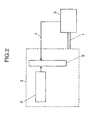
FIG. 1 is a diagram showing the basic configuration of a rotation angle sensor according to a first embodiment of the present invention; -
FIG. 2 is a block diagram showing the circuit configuration of the rotation angle sensor ofFIG. 1 ; -
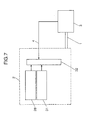
FIG. 3 is a diagram showing the basic configuration of atorque sensing portion 3 ofFIGS. 1 and2 ; -
FIGS. 4A and 4B are diagrams showing an operating principle of thetorque sensing portion 3 ofFIGS. 1 and2 ; -
FIG. 5 is a diagram showing detected waveforms representative of absolute rotation angle of a shaft portion detected by the rotation angle sensor ofFIG. 1 ; -
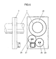
FIG. 6 is a diagram showing the basic configuration of a rotation angle sensor according to a second embodiment of the present invention; -
FIG. 7 is a block diagram showing the circuit configuration of the rotation angle sensor ofFIG. 6 ; -
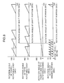
FIG. 8 is a diagram showing detected waveforms representative of absolute rotation angle of a shaft portion detected by the rotation angle sensor ofFIG. 6 ; -
FIG. 9 is a cross-sectional view showing the configuration of a torque sensing portion provided in a rotation angle sensor according to a third embodiment of the present invention; -
FIG. 10 is a top view showing the configuration of a rotation angle sensing portion provided in the rotation angle sensor according to the present embodiment; -
FIG. 11 is a cross-sectional view taken along lines A-A ofFIG. 10 ; -
FIG. 12 is a diagram showing the configuration of a conventional rotation angle sensor; and -
FIG. 13 is a diagram showing the configuration of another conventional rotation angle sensor. - Embodiments of the present invention are described hereinbelow with reference to the accompanying drawings, wherein the same or similar elements are designated by the same or similar reference numerals and a description of those elements may not be provided.
-
FIG. 1 is a diagram showing the basic configuration of a rotation angle sensor according to a first embodiment of the present invention,FIG. 2 is a block diagram showing the circuit configuration of the rotation angle sensor ofFIG. 1 ,FIG. 3 is a diagram showing the basic configuration of atorque sensing portion 3 ofFIGS. 1 and2 ,FIGS. 4A and 4B are diagrams showing an operating principle of thetorque sensing portion 3 ofFIGS. 1 and2 , andFIG. 5 is a diagram showing detected waveforms representative of absolute rotation angle of a shaft portion detected by the rotation angle sensor ofFIG. 1 . - Referring to
FIG. 1 , the rotation angle sensor according to the first embodiment of the present invention comprises a rotationangle sensing portion 2 for detecting rotation angle of theshaft portion 1, such as a steering shaft, thetorque sensing portion 3 and aserial communication line 4. The rotationangle sensing portion 2 includes a firstrotatable body 5 having a worm portion, a secondrotatable body 6 having a wheel portion which is joined to the worm portion of the firstrotatable body 5, amagnet 7 disposed at a central part of the secondrotatable body 6 and a first sensingpart 8 for detecting the rotation angle of theshaft portion 1. The worm portion of the firstrotatable body 5 is meshed with the wheel portion of the secondrotatable body 6, so that when the firstrotatable body 5 rotates, the secondrotatable body 6 rotates at a speed ratio determined by the ratio of the numbers of teeth of the worm portion and the wheel portion. - In the rotation angle sensor of the present embodiment, the rotation
angle sensing portion 2 is disposed at a steering column on a steering wheel side whereas thetorque sensing portion 3 is disposed at a steering gearbox on an axle side with respect to theshaft portion 1 which is a steering shaft connecting a steering wheel of a vehicle to an axle thereof. - The rotation
angle sensing portion 2 ofFIG. 1 further includes a microcomputer (hereinafter referred to as CPU) 9 for processing signals of thefirst sensing part 8 as shown inFIG. 2 . The CPU 9 is connected to thetorque sensing portion 3 via theserial communication line 4. - Described below is a case where a magnetic resistance element (MR element) is used as the
first sensing part 8. The magnetic resistance element outputs a sine wave signal and a cosine wave signal in analog form when the direction of a magnetic field varies. When detecting changes in the direction of the magnetic field of themagnet 7 by thefirst sensing part 8, it is possible to obtain one-cycle sine wave signal and cosine wave signal outputs for a 180-degree rotation. Upon receiving these outputs, the CPU 9 can calculate rotation angle of themagnet 7, that is, rotation angle of the secondrotatable body 6, by processing the entered outputs by means of an analog-to-digital (A/D) converter provided in the CPU 9. On the other hand, there is made an arrangement that enables the CPU 9 to take in high-accuracy, high-resolution rotation angle of 360 degrees or less detected by thetorque sensing portion 3 which is fitted and locked onto theshaft portion 1 via theserial communication line 4. - Next, the
torque sensing portion 3 is described with reference toFIG. 3 . - Referring to
FIG. 3 , thetorque sensing portion 3 includes astator 13, afirst resolver mechanism 14 and asecond resolver mechanism 15. Thefirst resolver mechanism 14 detects rotation angle of aninput shaft 10 of theshaft portion 1 joined to the steering wheel while thesecond resolver mechanism 15 detects rotation angle of anoutput shaft 12 of theshaft portion 1 joined to the axle. Thefirst resolver mechanism 14 includes a resolver output winding 16 disposed on thestator 13 and a resolver excitation winding 17 disposed on theinput shaft 10, whereas thesecond resolver mechanism 15 includes a resolver output winding 18 disposed on thestator 13 and a resolver excitation winding 19 disposed on theoutput shaft 12. Theinput shaft 10 and theoutput shaft 12 are linked to each other by atorsion bar 11. - Next, the working of the
torque sensing portion 3 is described with reference toFIGS. 4A and 4B . - Referring to
FIG. 4A , theresolver output windings stator 13 ofFIG. 3 constitute an excitation winding 20 and a position output winding 21, respectively. Excitation voltages sinωt and cosωt output from the excitation winding 20 are delivered to theresolver excitation windings input shaft 10 and theoutput shaft 12. As these excitation voltages are superimposed, a voltage proportional to the rotation angle θ of theinput shaft 10 or theoutput shaft 12 is fed back to the position output winding 21. In a signal diagram ofFIG. 4B , a horizontal axis shows time t and a vertical axis shows excitation voltage and position output voltage, wherein sinωt represents the excitation voltage output from the excitation winding 20 and sin(ωt+θ) represents the position output voltage fed back to the position output winding 21. A phase angle of the position output voltage relative to that of the excitation voltage gives the rotation angle of theinput shaft 10 or theoutput shaft 12. -
FIG. 5 shows individual detected waveforms representative of the rotation angle of the secondrotatable body 6 built in the rotationangle sensing portion 2 and rotation angle of a resolver built in thetorque sensing portion 3. In an upper part ofFIG. 5 , a horizontal axis shows the rotation angle of theshaft portion 1 and a vertical axis shows the rotation angle taken in from thetorque sensing portion 3. The rotation angle taken in from thetorque sensing portion 3 may be the rotation angle of theinput shaft 10 detected by thetorque sensing portion 3, for example. - On the other hand, in a lower part of
FIG. 5 , a horizontal axis shows the rotation angle of theshaft portion 1 and a vertical axis shows the rotation angle of the secondrotatable body 6. The rotation angle of the secondrotatable body 6 is what is calculated by the CPU 9 from the signals of thefirst sensing part 8. The first sensing part 8 (magnetic resistance element) detects changes in the direction of the magnetic field of themagnet 7 which is disposed at the central part of the secondrotatable body 6 and outputs the one-cycle sine wave signal and cosine wave signal for one-half rotation of themagnet 7. It is possible to calculate the rotation angle of the secondrotatable body 6 by processing these outputs by the CPU 9. - Next, a rotation angle sensing method of the rotation angle sensor according to the first embodiment of the present invention is described. Referring to
FIGS. 1 and2 , when theshaft portion 1 rotates, themagnet 7 disposed at the center of the secondrotatable body 6 rotates as a result of rotation of the wheel portion of the secondrotatable body 6 joined to the worm portion of the firstrotatable body 5 of the rotationangle sensing portion 2. - Provided that the number of teeth of the worm portion of the first
rotatable body 5 is "a" and the number of teeth of the wheel portion of the secondrotatable body 6 is "b", the secondrotatable body 6 turns at a speed a/b times a rotating speed of the firstrotatable body 5. As the numbers of teeth "a" and "b" of the individual gears of the firstrotatable body 5 and the secondrotatable body 6 are properly selected, the secondrotatable body 6 rotates at a speed sufficiently lower than the rotating speed of the firstrotatable body 5. The outputs of thefirst sensing part 8 located at a position opposed to themagnet 7 disposed at the central part of the secondrotatable body 6 vary when changes in the direction of the magnetic field caused by rotation of themagnet 7 are detected. The CPU 9 takes in the outputs of thefirst sensing part 8 through the A/D converter. The secondrotatable body 6 turns 180 degrees for a 720-degree rotation angle of theshaft portion 1. The rotation angle of theshaft portion 1 is calculated by the CPU 9 by processing the signals of thefirst sensing part 8. - On the other hand, the
torque sensing portion 3 disposed coaxially with theshaft portion 1 determines angle of torsion of thetorsion bar 11 from a difference between rotation angles of thefirst resolver mechanism 14 and thesecond resolver mechanism 15 as shown inFIGS. 3 and4 and converts the angle of torsion into a torque value. The CPU 9 of the rotationangle sensing portion 2 takes in the rotation angle of theinput shaft 10 of theshaft portion 1 which is joined to the steering wheel from thefirst resolver mechanism 14 through theserial communication line 4.FIG. 5 depicts behaviors of the rotation angle of thetorque sensing portion 3 and the rotation angle of the secondrotatable body 6 which vary with rotation of theshaft portion 1.FIG. 5 shows that thetorque sensing portion 3 can detect the rotation angle of theshaft portion 1 with high accuracy and high resolution within a rotation angle sensing range of 45 degrees. - Now, specific processing steps of the rotation angle sensing method are described. A procedure for detecting absolute rotation angle of rotation angle A of the
shaft portion 1 is described with reference toFIG. 5 , for example. The rotationangle sensing portion 2 determines the rotation angle A measured from an initial position (0 degrees) of theshaft portion 1 from rotation angle C of the secondrotatable body 6. Frequency of revolutions of thefirst resolver mechanism 14 from an initial position thereof is determined by dividing the rotation angle A by 45 degrees which is the rotation angle sensing range of thefirst resolver mechanism 14 of thetorque sensing portion 3.FIG. 5 shows rotation angle B in a fourth rotating cycle. On the other hand, the rotation angle B of thetorque sensing portion 3 at the rotation angle A of theshaft portion 1 is taken into the rotationangle sensing portion 2. - In this case, the absolute rotation angle of the rotation angle A of the
shaft portion 1 is obtained by adding the rotation angle B of thetorque sensing portion 3 to three cycles of the 45-degree rotation angle sensing range of thefirst resolver mechanism 14 of thetorque sensing portion 3. Specifically, because "45 degrees x {(rotation angle A)/45 degrees} = 45 degrees x 3 = 135 degrees (where the value in {} is an integer)", it is possible to calculate the absolute rotation angle of the rotation angle A by "135 degrees + (rotation angle B)". - A second embodiment of the present invention is now described with reference to
FIGS. 6 to 8 .FIG. 6 is a diagram showing the basic configuration of a rotation angle sensor according to the second embodiment of the present invention,FIG. 7 is a block diagram showing the circuit configuration of the rotation angle sensor ofFIG. 6 , andFIG. 8 is a diagram showing detected waveforms representative of absolute rotation angle of a shaft portion detected by the rotation angle sensor ofFIG. 6 . - Referring to
FIGS. 6 and7 , the rotation angle sensor according to the second embodiment of the present invention comprises a rotationangle sensing portion 2 for detecting rotation angle of theshaft portion 1, such as a steering shaft, atorque sensing portion 3 and aserial communication line 4. The rotationangle sensing portion 2 includes a thirdrotatable body 25 made of a gear joined to theshaft portion 1, a fourthrotatable body 26 made of a gear joined to the gear of the thirdrotatable body 25, amagnet 27 disposed at a central part of the fourthrotatable body 26, a fifthrotatable body 29 made of a gear joined to the gear of the fourthrotatable body 26 and amagnet 30 disposed at a central part of the fifthrotatable body 29. The numbers of teeth of the fourthrotatable body 26 and the fifthrotatable body 29 are made different from each other. - The rotation
angle sensing portion 2 ofFIG. 6 further includes asecond sensing part 28 located at a position opposed to themagnet 27 of the fourthrotatable body 26 for detecting rotation angle of the fourthrotatable body 26 and athird sensing part 31 located at a position opposed to themagnet 30 of the fifthrotatable body 29 for detecting rotation angle of the fifthrotatable body 29. Thesecond sensing part 28 and thethird sensing part 31 are connected to a CPU (microcomputer) 32 as shown inFIG. 7 . - As in the foregoing first embodiment, magnetic resistance elements are used in the
second sensing part 28 and thethird sensing part 31 and outputs thereof are processed by means of an A/D converter provided in theCPU 32 to calculate rotation angles of themagnet 27 and themagnet 30, that is, the rotation angles of the fourthrotatable body 26 and the fifthrotatable body 29. On the other hand, there is made an arrangement that enables theCPU 32 to take in high-accuracy, high-resolution rotation angle of 360 degrees or less detected by thetorque sensing portion 3 which is fitted and locked onto theshaft portion 1 via theserial communication line 4. Thetorque sensing portion 3 of the present embodiment has the same configuration as thetorque sensing portion 3 of the aforementioned first embodiment. -
FIG. 8 shows individual detected waveforms representative of the rotation angles of the fourth and fifthrotatable bodies angle sensing portion 2 and rotation angle of a resolver built in thetorque sensing portion 3. In a first part ofFIG. 8 from top, a horizontal axis shows the rotation angle of theshaft portion 1 and a vertical axis shows the rotation angle of the fourthrotatable body 26. This latter rotation angle is what is calculated by theCPU 32 from signals of thesecond sensing part 28. In a second part ofFIG. 8 from top, a horizontal axis shows the rotation angle of theshaft portion 1 and a vertical axis shows the rotation angle of the fifthrotatable body 29. This latter rotation angle is what is calculated by theCPU 32 from signals of thethird sensing part 31. In a third part ofFIG. 8 from top, a horizontal axis shows the rotation angle of theshaft portion 1 and a vertical axis shows a difference between the rotation angles of the fourthrotatable body 26 and the fifthrotatable body 29. In a fourth part ofFIG. 8 from top, a horizontal axis shows the rotation angle of theshaft portion 1 and a vertical axis shows the rotation angle taken in from thetorque sensing portion 3. The rotation angle taken in from thetorque sensing portion 3 is rotation angle of aninput shaft 10. - The second sensing part 28 (magnetic resistance element) detects changes in the direction of a magnetic field of the
magnet 27 which is disposed at the central part of the fourthrotatable body 26 and outputs one-cycle sine wave and cosine wave signals for one-half rotation of themagnet 27. It is possible to calculate the rotation angle of the fourthrotatable body 26 by processing these outputs by theCPU 32. Thethird sensing part 31 detects changes in the direction of a magnetic field of themagnet 30 which is disposed at the central part of the fifthrotatable body 29 and outputs one-cycle sine wave and cosine wave signals for one-half rotation of themagnet 30. It is possible to calculate the rotation angle of the fifthrotatable body 29 by processing these outputs by theCPU 32. Thetorque sensing portion 3 uses the resolver as in the first embodiment. - Next, a rotation angle sensing method of the rotation angle sensor according to the second embodiment of the present invention is described.
- Referring to
FIGS. 6 to 8 , when theshaft portion 1 rotates, the fourthrotatable body 26 is caused to rotate by rotation of the gear of the fourthrotatable body 26 joined to the gear of the thirdrotatable body 25 of the rotationangle sensing portion 2. At the same time, the fifthrotatable body 29 is caused to rotate by the gear of the fifthrotatable body 29 joined to the gear of the fourthrotatable body 26. Since the number of the teeth of the gear of the fourthrotatable body 26 and the number of the teeth of the gear of the fifthrotatable body 29 differ from each other, the fourth and fifthrotatable bodies second sensing part 28 located at the position opposed to themagnet 27 disposed at the central part of the fourthrotatable body 26 vary when the direction of the magnetic field of themagnet 27 of the rotating fourthrotatable body 26 is detected. TheCPU 32 takes in the outputs of thesecond sensing part 28 through the A/D converter provided in theCPU 32. At the same time, theCPU 32 takes in the outputs of thethird sensing part 31 for detecting the direction of the magnetic field of themagnet 30 disposed at the central part of the fifthrotatable body 29 through the A/D converter provided in theCPU 32. Since thetorque sensing portion 3 uses the resolver as in the first embodiment, it is possible to detect the rotation angle of theshaft portion 1 with high accuracy and high resolution within a rotation angle sensing range of 45 degrees. TheCPU 32 of the rotationangle sensing portion 2 takes in the rotation angle of the input shaft of theshaft portion 1 which is linked to the steering wheel via theserial communication line 4 from thefirst resolver mechanism 14. - Now, specific processing steps of the rotation angle sensing method are described. A procedure for detecting absolute rotation angle of rotation angle A of the
shaft portion 1 is described with reference toFIG. 8 , for example. As shown inFIG. 8 , the rotationangle sensing portion 2 takes in rotation angle B obtained from thetorque sensing portion 3 when the rotation angle of theshaft portion 1 is "A". On the other hand, it is possible to determine the rotation angle A measured from an initial position (0 degrees) of theshaft portion 1 from the difference E between rotation angle C of the fourthrotatable body 26 and rotation angle D of the fifthrotatable body 29 when the rotation angle of theshaft portion 1 is "A". Frequency of revolutions of thefirst resolver mechanism 14 of thetorque sensing portion 3 from an initial position thereof is determined by dividing the rotation angle A by 45 degrees which is a rotation angle sensing range of thefirst resolver mechanism 14.FIG. 8 shows the rotation angle B in a sixth rotating cycle. - In this case, the absolute rotation angle of the rotation angle A of the
shaft portion 1 is obtained by adding the rotation angle B of thetorque sensing portion 3 to five cycles of the 45-degree rotation angle sensing range of thefirst resolver mechanism 14 of thetorque sensing portion 3. Specifically, because "45 degrees x {(rotation angle A)/45 degrees} = 45 degrees x 5 = 225 degrees (where the value in {} is an integer)", it is possible to calculate the absolute rotation angle of the rotation angle A by "225 degrees + (rotation angle B)". - According to the first and second embodiments of the present invention, it is possible to detect the rotation angle of the shaft portion by the rotation angle sensing portion. Especially because the angle of torsion of the torsion bar is made smaller than the rotation angle of the shaft portion and the rotation angle of the shaft portion is detected based on the angle of torsion of the torsion bar, it is possible to detect the rotation angle of the shaft portion with high accuracy and high resolution.
- A third embodiment of the present invention is now described with reference to the drawings.
-
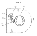
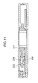
FIG. 9 is a cross-sectional view showing the configuration of a torque sensing portion provided in a rotation angle sensor according to the third embodiment of the present invention,FIG. 10 is a top view showing the configuration of a rotation angle sensing portion provided in the rotation angle sensor according to the present embodiment, andFIG. 11 is a cross-sectional view taken along lines A-A ofFIG. 10 . - Referring to
FIGS. 9 to 11 , the rotation angle sensor according to the third embodiment of the present invention comprises ashaft portion 208 formed in a single rigid structure in which aninput shaft 204 and anoutput shaft 206 are joined at both ends of atorsion bar 202, a torque sensing portion for detecting torque acting on theshaft portion 208 and the rotation angle sensing portion for detecting rotation angle of theshaft portion 208. - As shown in
FIG. 9 , the torque sensing portion of the rotation angle sensor according to the present embodiment includes a firstrotatable body 210 and a secondrotatable body 212 which are joined to theshaft portion 208 as if sandwiching thetorsion bar 202, a firstring magnet portion 214 and a secondring magnet portion 216 which are held by the first and secondrotatable bodies rotatable bodies magnetism sensing device 218 and a secondmagnetism sensing device 220 which are disposed face to face with the magnetic poles of the first and secondring magnet portions magnetism sensing device 218 and the secondmagnetism sensing device 220 detect changes in magnetic fields. Provided that the number of the magnetic poles of each of the firstring magnet portion 214 and the secondring magnet portion 216 is X, an angle Y per pole is (360 degrees)/X. Also, it is assumed that a maximum value of a difference between rotation angles of the firstrotatable body 210 and the secondrotatable body 212 caused by the occurrence of torque is Z (Z<(Y/2)). - As shown in
FIGS. 10 and11 , the rotation angle sensing portion of the rotation angle sensor according to the present embodiment includes a synchronizingrotatable body 211 which is joined to theshaft portion 208 and synchronizes with the firstrotatable body 210 of the aforementioned torque sensing portion, a thirdrotatable body 222 and a fourthrotatable body 224 which synchronize with the synchronizingrotatable body 211, athird magnet portion 228 and a fourth magnet portion (not shown) which are held by the third and fourthrotatable bodies rotatable bodies magnetism sensing device 226 and a fourthmagnetism sensing device 227 which are disposed face to face with the magnetic poles of the thirdmagnetism sensing device 226 and the fourth magnet portion, respectively. The thirdmagnetism sensing device 226 and the fourthmagnetism sensing device 227 detect changes in magnetic fields. - The synchronizing
rotatable body 211 and the third and fourthrotatable bodies rotatable body 222 meshed with teeth of the synchronizingrotatable body 211 and teeth of the fourthrotatable body 224 meshed with the teeth of the thirdrotatable body 222. Gears of the third and fourthrotatable bodies rotatable body 222 to the number of revolutions of the synchronizingrotatable body 211 differs from the ratio of the number of revolutions of the fourthrotatable body 224 to the number of revolutions of the synchronizingrotatable body 211. Provided that the number of the teeth of the gear of the synchronizingrotatable body 211 is α, the number of the teeth of the gear of the thirdrotatable body 222 is β and the number of the teeth of the gear of the fourthrotatable body 224 is γ, the thirdrotatable body 222 turns at a speed α/β times a rotating speed of the synchronizingrotatable body 211 and the fourthrotatable body 224 turns at a speed α/γ times the rotating speed of the synchronizingrotatable body 211. - It is possible to determine rotation angle of the synchronizing
rotatable body 211 over multiple revolutions thereof from a difference between rotation angles of the thirdrotatable body 222 and the fourthrotatable body 224 by properly selecting the numbers of the teeth α, β, γ of the gears. - Next, the working of the rotation angle sensing portion and the torque sensing portion of the rotation angle sensor of the present embodiment is described.
- In the absence of torque, the
input shaft 204, thetorsion bar 202 and theoutput shaft 206 rotate as a single structure, so that when theinput shaft 204 rotates, the secondrotatable body 212 also rotates in synchronism with theinput shaft 204. When theoutput shaft 206 rotates, the third and fourthrotatable bodies rotatable body 210 and the synchronizingrotatable body 211 rotate in synchronism with each other. It is possible to estimate which one of the X number of the magnetic poles of the firstring magnet portion 214 on the firstrotatable body 210 is disposed face to face with the firstmagnetism sensing device 218 and determine which one of the Y-degree angular positions of the individual magnetic poles faces the firstmagnetism sensing device 218 with reference to the rotation angle of the synchronizingrotatable body 211. - When the torque occurs, the second
rotatable body 212 deviates from the firstrotatable body 210 in angular position by Z degrees at a maximum. In this case, it is supposed that one of the X number of the magnetic poles of the secondring magnet portion 216 located at the same position as the firstrotatable body 210 faces the secondmagnetism sensing device 220 or, because Z<(Y/2), the magnetic pole adjacent to the magnetic pole located at the same position as the firstrotatable body 210 faces the secondmagnetism sensing device 220. In addition, the secondrotatable body 212 does not show the Y-degrees angular position of the same magnetic pole of the secondring magnet portion 216 while the secondrotatable body 212 deviates by Z degrees due to the occurrence of the torque. Therefore, it is possible to detect the Y-degree angular position of the magnetic pole of the secondring magnet portion 216 facing the secondmagnetism sensing device 220. - Further, the rotation angle sensing portion and the torque sensing portion are configured as a rotation angle sensor module and a torque sensor module, respectively, and the individual modules are separately mounted on the
shaft portion 208. For example, the rotation angle sensor module is disposed at a steering column portion and the torque sensor module is disposed at a steering gearbox portion. - As specific means for correcting torque detected by the torque sensing portion, rotation angle data of the first
rotatable body 210 and rotation angle data of the secondrotatable body 212 corresponding to the synchronizingrotatable body 211 are prestored in a memory. This correcting means verifies which magnetic pole of the firstring magnet portion 214 of the firstrotatable body 210 faces the firstmagnetism sensing device 218 and what angle is detected by the firstrotatable body 210 from the rotation angle of the synchronizingrotatable body 211 and the rotation angle of the firstrotatable body 210 and corrects the rotation angle of the firstrotatable body 210 based on the rotation angle data prestored in the memory. This operation is similarly made for the secondrotatable body 212. - As an example, it is assumed that the rotation angle of the first
rotatable body 210 detected by the firstmagnetism sensing device 218 is "a" degrees, the rotation angle of the secondrotatable body 212 detected by the secondmagnetism sensing device 220 is "b" degrees, and the rotation angle of the synchronizingrotatable body 211 detected by the thirdmagnetism sensing device 226 and the fourthmagnetism sensing device 227 is "c" degrees. - Since the synchronizing
rotatable body 211 and the firstrotatable body 210 rotate in synchronism with each other, it is possible to determine from the rotation angle "c" of the synchronizingrotatable body 211 that one of the X number of the magnetic poles on the firstrotatable body 210 detected by the firstmagnetism sensing device 218 is a dth magnetic pole. Further, if the rotation angle of the synchronizingrotatable body 211 is "c" and angle correction data is "e" when the rotation angle of the firstrotatable body 210 is "a", the rotation angle of the firstrotatable body 210 becomes (a-e) degrees. - There is a case where an angular deviation of the second
rotatable body 212 from the synchronizingrotatable body 211 occurs due to torque acting on the firstrotatable body 210. Even in this case, the detected magnetic pole is the dth, (d-1)th or (d+1)th magnetic pole of the X number of the magnetic poles of the secondring magnet portion 216 because the amount of the angular deviation is smaller than the angular width (Y/2) of each magnetic pole. Therefore, the angle "b" of the secondrotatable body 212 is uniquely determined for the angle "c" of the synchronizingrotatable body 211. If the rotation angle of the synchronizingrotatable body 211 is "c" and angle correction data is "f" when the rotation angle of the firstrotatable body 210 is "b", the rotation angle of the secondrotatable body 212 becomes (b-f) degrees. The torque sensing portion detects a torque of (a-e)-(b-f). - Accordingly, it is possible to improve torque detecting accuracy because the rotation angles of the first and second rotatable bodies are corrected based on the rotation angle of the synchronizing rotatable body of the rotation angle sensing portion even when the rotation angle of the first rotatable body and the rotation angle of the second rotatable body of the torque sensing portion differ from true rotation angles due to variations in size of the magnetic poles, for instance.
- According to the third embodiment of the present invention, it is possible to improve the torque detecting accuracy as the rotation angle sensing portion and the torque sensing portion operate in a cooperative fashion. In particular, even when the module of the rotation angle sensing portion is disposed at the steering column portion and the module of the torque sensing portion is disposed at the steering gearbox portion, the rotation angle sensing portion and the torque sensing portion can improve the detecting accuracy, working cooperatively with each other.
- From the individual embodiments thus far described, the present invention is summarized as mentioned hereunder. Specifically, a rotation angle sensor of the invention comprises a shaft portion having a torsion bar, a rotation angle sensing portion for detecting rotation angle of the shaft portion, and a torque sensing portion for detecting angle of torsion of the torsion bar, wherein the rotation angle sensing portion and the torque sensing portion improve their own detecting accuracies by using each other's detecting result.
- In the aforementioned rotation angle sensor, the rotation angle sensor uses the detecting result of the torque sensing portion when detecting the rotation angle of the shaft portion. On the other hand, the torque sensing portion uses the detecting result of the rotation angle sensing portion when detecting the torque acting on the shaft portion. Accordingly, it is possible to detect the rotation angle and torque of the shaft portion with higher accuracy and higher resolution as compared to a conventional arrangement in which the rotation angle and torque are separately detected.
- In the aforementioned rotation angle sensor, the rotation angle sensing portion preferably detects the rotation angle of the shaft portion based on rotation angle of an input side or an output side of the torsion bar which is used by the torque sensing portion when detecting the angle of torsion of the torsion bar.
- In this case, it is possible to detect the rotation angle of the shaft portion with higher accuracy and higher resolution compared to a case where the rotation angle of the shaft portion is calculated only from the rotation angle detected by the rotation angle sensing portion.
- In the aforementioned rotation angle sensor, the rotation angle sensing portion preferably includes a first rotatable body which is joined to the shaft portion and rotates in synchronism with rotation of the shaft portion, a second rotatable body which rotates in synchronism with rotation of the first rotatable body, and a first sensing part for detecting rotation angle of the second rotatable body, wherein the second rotatable body rotates at a lower speed than the first rotatable body.
- In this case, it is possible to detect the rotation angle of the shaft portion over multiple revolutions thereof because the rotation angle of the shaft portion is detected from the rotation angle of the second rotatable body which rotates in synchronism with but at a lower speed than the first rotatable body.
- In the aforementioned rotation angle sensor, the rotation angle sensing portion preferably includes a third rotatable body which is joined to the shaft portion and rotates in synchronism with rotation of the shaft portion, a fourth rotatable body which rotates in synchronism with the third rotatable body, a fifth rotatable body which rotates in synchronism with the fourth rotatable body, and second and third sensing parts for detecting rotation angles of the fourth and fifth rotatable bodies, wherein the ratio of the number of revolutions of the fourth rotatable body to the number of revolutions of the third rotatable body and the ratio of the number of revolutions of the fifth rotatable body to the number of revolutions of the third rotatable body differ from each other.
- In this case, it is possible to detect the rotation angle of the shaft portion over multiple revolutions thereof because the rotation angle of the shaft portion is detected from a difference between the rotation angles of the fourth and fifth rotatable bodies which rotate at the different ratios of the number of revolutions to the number of revolutions of the third rotatable body which rotates in synchronism with the shaft portion.
- In the aforementioned rotation angle sensor, the torque sensing portion preferably includes first and second resolver mechanisms each having a resolver excitation winding joined to the torsion bar and a resolver output winding which outputs a signal corresponding to rotation angle of the torsion bar produced by excitation by the resolver excitation winding as a result of rotation of the torsion bar, wherein the first resolver mechanism is disposed at the input side of the torsion bar and the second resolver mechanism is disposed at the output side of the torsion bar.
- In this case, it is possible to detect the rotation angles of the input side and the output side of the torsion bar with high accuracy without the influence of a magnetic field or an electric field.
- In the aforementioned rotation angle sensor, the torque sensing portion preferably includes first and second rotatable bodies which are joined respectively to the input side and the output side of the torsion bar in such a manner that each of the first and second rotatable bodies sandwiches the torsion bar, whereby the torque sensing portion detects the angle of torsion of the torsion bar based on a difference between rotation angles of the first and second rotatable bodies, and the rotation angle sensing portion preferably includes a synchronizing rotatable body which is joined to the shaft portion and rotates in synchronism with rotation of the first rotatable body, whereby the rotation angle sensing portion detects the rotation angle of the shaft portion based on rotation angle of the synchronizing rotatable body, wherein the rotation angles of the first and second rotatable bodies are corrected based on the rotation angle of the synchronizing rotatable body.
- In this case, it is possible to improve detecting accuracy of the rotation angles of the first and second rotatable bodies because when the torque sensing portion detects the rotation angles of the input side and the output side of the torsion bar, the rotation angles of the first and second rotatable bodies used for detection of the rotation angles of individual shafts of the torsion bar are corrected based on the rotation angle of the synchronizing rotatable body of the rotation angle sensing portion for detecting the rotation angle of the shaft portion.
- In the aforementioned rotation angle sensor, the rotation angles of the first and second rotatable bodies are preferably corrected based on prestored data on correcting angles by which the rotation angles of the first and second rotatable bodies are to be corrected with reference to the rotation angle of the synchronizing rotatable body.
- In this case, it is possible to efficiently correct the rotation angles of the first and second rotatable bodies because data necessary for correcting the rotation angles of the first and second rotatable bodies are collected and stored in advance and can be used when making corrections.
- In the aforementioned rotation angle sensor, the rotation angle sensing portion and the torque sensing portion are preferably configured as modules separately mounted on the shaft portion, wherein the module of the rotation angle sensing portion is disposed at a steering column portion and the module of the torque sensing portion is disposed at a steering gearbox portion.
- In this case, it is possible to enhance detecting accuracy of the rotation angle and torque of the shaft portion by the rotation angle sensing portion disposed at the steering column portion and the torque sensing portion disposed at the steering gearbox portion.
- A rotation angle sensor according to the present invention can be mounted on a steering shaft, for instance. The rotation angle sensor with a simple configuration can detect absolute rotation angle of a multi-turn steering wheel with high accuracy and high resolution and can be used in power steering systems of various kinds of vehicles, for instance.
- The rotation angle sensor of the present invention, in which a rotation angle sensing portion and a torque sensing portion work cooperatively with each other, can provide improved detecting accuracy and can be used in power steering systems of various kinds of vehicles, for instance.
Claims (8)
- A rotation angle sensor comprising:a shaft portion having a torsion bar;a rotation angle sensing portion for detecting rotation angle of the shaft portion; anda torque sensing portion for detecting angle of torsion of the torsion bar;wherein the rotation angle sensing portion and the torque sensing portion improve their own detecting accuracies by using each other's detecting result.
- The rotation angle sensor as recited in claim 1,
wherein the rotation angle sensing portion detects the rotation angle of the shaft portion based on rotation angle of an input side or an output side of the torsion bar which is used by the torque sensing portion when detecting the angle of torsion of the torsion bar. - The rotation angle sensor as recited in claim 2,
wherein the rotation angle sensing portion includes:a first rotatable body which is joined to the shaft portion and rotates in synchronism with rotation of the shaft portion;a second rotatable body which rotates in synchronism with rotation of the first rotatable body; anda first sensing part for detecting rotation angle of the second rotatable body; andthe second rotatable body rotates at a lower speed than the first rotatable body. - The rotation angle sensor as recited in claim 2,
wherein the rotation angle sensing portion includes:a third rotatable body which is joined to the shaft portion and rotates in synchronism with rotation of the shaft portion;a fourth rotatable body which rotates in synchronism with rotation of the third rotatable body;a fifth rotatable body which rotates in synchronism with rotation of the fourth rotatable body; andsecond and third sensing parts for detecting rotation angles of the fourth and fifth rotatable bodies; andthe ratio of the number of revolutions of the fourth rotatable body to the number of revolutions of the third rotatable body and the ratio of the number of revolutions of the fifth rotatable body to the number of revolutions of the third rotatable body differ from each other. - The rotation angle sensor as recited in claim 2,
wherein the torque sensing portion includes first and second resolver mechanisms each having a resolver excitation winding joined to the torsion bar and a resolver output winding which outputs a signal corresponding to rotation angle of the torsion bar produced by excitation by the resolver excitation winding as a result of rotation of the torsion bar, and
the first resolver mechanism is disposed at the input side of the torsion bar and the second resolver mechanism is disposed at the output side of the torsion bar. - The rotation angle sensor as recited in claim 1, wherein the torque sensing portion includes first and second rotatable bodies which are joined respectively to the input side and the output side of the torsion bar in such a manner that each of the first and second rotatable bodies sandwiches the torsion bar, whereby the torque sensing portion detects the angle of torsion of the torsion bar based on a difference between rotation angles of the first and second rotatable bodies,
the rotation angle sensing portion includes a synchronizing rotatable body which is joined to the shaft portion and rotates in synchronism with rotation of the first rotatable body, whereby the rotation angle sensing portion detects the rotation angle of the shaft portion based on rotation angle of the synchronizing rotatable body, and
the rotation angles of the first and second rotatable bodies are corrected based on the rotation angle of the synchronizing rotatable body. - The rotation angle sensor as recited in claim 6, wherein the rotation angles of the first and second rotatable bodies are corrected based on prestored data on correcting angles by which the rotation angles of the first and second rotatable bodies are to be corrected with reference to the rotation angle of the synchronizing rotatable body.
- The rotation angle sensor as recited in one of claims 1 to 7, wherein the rotation angle sensing portion and the torque sensing portion are configured as modules separately mounted on the shaft portion, and
the module of the rotation angle sensing portion is disposed at a steering column portion and the module of the torque sensing portion is disposed at a steering gearbox portion.
Applications Claiming Priority (3)
| Application Number | Priority Date | Filing Date | Title |
|---|---|---|---|
| JP2006107353A JP2007278924A (en) | 2006-04-10 | 2006-04-10 | Turning angle detector |
| JP2006107352A JP2007278923A (en) | 2006-04-10 | 2006-04-10 | Rotation angle and torque sensor |
| PCT/JP2007/057805 WO2007119701A1 (en) | 2006-04-10 | 2007-04-09 | Rotation angle detector |
Publications (3)
| Publication Number | Publication Date |
|---|---|
| EP2006648A2 EP2006648A2 (en) | 2008-12-24 |
| EP2006648A9 true EP2006648A9 (en) | 2009-07-29 |
| EP2006648A4 EP2006648A4 (en) | 2012-04-04 |
Family
ID=38609462
Family Applications (1)
| Application Number | Title | Priority Date | Filing Date |
|---|---|---|---|
| EP07741241A Withdrawn EP2006648A4 (en) | 2006-04-10 | 2007-04-09 | Rotation angle detector |
Country Status (3)
| Country | Link |
|---|---|
| US (1) | US7775129B2 (en) |
| EP (1) | EP2006648A4 (en) |
| WO (1) | WO2007119701A1 (en) |
Families Citing this family (32)
| Publication number | Priority date | Publication date | Assignee | Title |
|---|---|---|---|---|
| US7677114B2 (en) * | 2006-03-31 | 2010-03-16 | Sona Koyo Steering Systems Ltd. | Torque sensor for electric power steering system |
| KR20090073057A (en) * | 2006-05-24 | 2009-07-02 | 티티 일렉트로닉스 테크놀러지 리미티드 | Multiturn rotational sensor |
| US7789191B2 (en) * | 2007-04-24 | 2010-09-07 | Sona Koyo Steering Systems Ltd. | Electric power assist module for steering system |
| US8024956B2 (en) * | 2008-09-02 | 2011-09-27 | Infineon Technologies Ag | Angle measurement system |
| JP4893721B2 (en) * | 2008-10-06 | 2012-03-07 | トヨタ自動車株式会社 | Rotation angle detector |
| EP2491335B1 (en) * | 2009-10-19 | 2016-12-07 | Sensata Technologies, Inc. | Multi-turn sensor |
| JP5524600B2 (en) * | 2009-12-24 | 2014-06-18 | オークマ株式会社 | Multi revolution detector |
| JP5589458B2 (en) * | 2010-03-15 | 2014-09-17 | パナソニック株式会社 | Rotation angle / torque detection device |
| DE102010033769A1 (en) * | 2010-08-09 | 2012-02-09 | Valeo Schalter Und Sensoren Gmbh | Device with a torque sensor and a rotation angle sensor |
| TWI500907B (en) * | 2011-01-07 | 2015-09-21 | Oriental Motor Co Ltd | Apparatus for detecting multi-turn absolute rotation angle and method for detecting the same |
| JP5616281B2 (en) * | 2011-04-15 | 2014-10-29 | 日立オートモティブシステムズステアリング株式会社 | Torque sensor and power steering device |
| JP2012251861A (en) * | 2011-06-02 | 2012-12-20 | Renesas Electronics Corp | Electronic flowmeter |
| JP5545769B2 (en) | 2011-07-12 | 2014-07-09 | オリエンタルモーター株式会社 | Apparatus and method for calculating absolute displacement |
| DE102011111846A1 (en) * | 2011-08-27 | 2013-02-28 | Volkswagen Aktiengesellschaft | Device for determining rotational torque and steering angle of steering system in motor car during steering maneuvers, has sensors for detecting part of magnetic field and overlapping of two magnetic fields to determine torque and angle |
| JP5420624B2 (en) | 2011-11-14 | 2014-02-19 | オリエンタルモーター株式会社 | Multi-rotation absolute rotation angle detection device and method for detecting absolute rotation angle |
| JP5953955B2 (en) * | 2012-06-07 | 2016-07-20 | 株式会社ジェイテクト | Torque sensor |
| KR102224460B1 (en) * | 2014-11-11 | 2021-03-08 | 엘지이노텍 주식회사 | Torque and angle sensor |
| US11560169B2 (en) | 2015-06-11 | 2023-01-24 | Steering Solutions Ip Holding Corporation | Retractable steering column system and method |
| US10343706B2 (en) | 2015-06-11 | 2019-07-09 | Steering Solutions Ip Holding Corporation | Retractable steering column system, vehicle having the same, and method |
| US10577009B2 (en) | 2015-06-16 | 2020-03-03 | Steering Solutions Ip Holding Corporation | Retractable steering column assembly and method |
| DE102016111473A1 (en) | 2015-06-25 | 2016-12-29 | Steering Solutions Ip Holding Corporation | STATIONARY STEERING WHEEL ASSEMBLY AND METHOD |
| US10421476B2 (en) | 2016-06-21 | 2019-09-24 | Steering Solutions Ip Holding Corporation | Self-locking telescope actuator of a steering column assembly |
| US10457313B2 (en) | 2016-06-28 | 2019-10-29 | Steering Solutions Ip Holding Corporation | ADAS wheel locking device |
| US10363958B2 (en) | 2016-07-26 | 2019-07-30 | Steering Solutions Ip Holding Corporation | Electric power steering mode determination and transitioning |
| US10189496B2 (en) | 2016-08-22 | 2019-01-29 | Steering Solutions Ip Holding Corporation | Steering assembly having a telescope drive lock assembly |
| US20180086378A1 (en) * | 2016-09-27 | 2018-03-29 | Steering Solutions Ip Holding Corporation | Position detection system for a retractable steering column |
| US10351160B2 (en) | 2016-11-30 | 2019-07-16 | Steering Solutions Ip Holding Corporation | Steering column assembly having a sensor assembly |
| US10370022B2 (en) | 2017-02-13 | 2019-08-06 | Steering Solutions Ip Holding Corporation | Steering column assembly for autonomous vehicle |
| US10385930B2 (en) | 2017-02-21 | 2019-08-20 | Steering Solutions Ip Holding Corporation | Ball coupling assembly for steering column assembly |
| US10974756B2 (en) | 2018-07-31 | 2021-04-13 | Steering Solutions Ip Holding Corporation | Clutch device latching system and method |
| US10996085B2 (en) | 2019-01-09 | 2021-05-04 | Infineon Technologies Ag | Sensor alignment using homogeneous test mode |
| JP7414398B2 (en) * | 2019-03-29 | 2024-01-16 | ミネベアミツミ株式会社 | absolute encoder |
Family Cites Families (15)
| Publication number | Priority date | Publication date | Assignee | Title |
|---|---|---|---|---|
| DE19506938A1 (en) * | 1995-02-28 | 1996-08-29 | Bosch Gmbh Robert | Method and device for measuring the angle of a rotatable body |
| JP3587674B2 (en) | 1998-01-07 | 2004-11-10 | アルプス電気株式会社 | Rotation angle sensor, torque sensor using this rotation angle sensor, electric power steering device using this torque sensor |
| JP2001091375A (en) * | 1999-09-21 | 2001-04-06 | Koyo Seiko Co Ltd | Torque sensor and electrically-driven steering device using the same |
| DE10041090A1 (en) * | 2000-08-22 | 2002-03-07 | Bosch Gmbh Robert | Method for self-calibration of a torsion angle measured by a torque and protractor |
| JP2002213944A (en) * | 2001-01-18 | 2002-07-31 | Niles Parts Co Ltd | Instrument for measuring rotational angle |
| JP4759845B2 (en) * | 2001-05-21 | 2011-08-31 | パナソニック株式会社 | Rotation angle detector |
| US6546322B2 (en) * | 2001-07-11 | 2003-04-08 | Trw Inc. | Method of controlling a vehicle steering apparatus |
| WO2004062983A1 (en) * | 2003-01-10 | 2004-07-29 | Nsk Ltd. | Steering control device |
| JP3867682B2 (en) * | 2003-05-29 | 2007-01-10 | 日産自動車株式会社 | Vehicle steering system |
| JP2005195363A (en) * | 2003-12-26 | 2005-07-21 | Koyo Seiko Co Ltd | Rotation angle detector and torque detector |
| JP2005201712A (en) * | 2004-01-14 | 2005-07-28 | Matsushita Electric Ind Co Ltd | Detection device of rotation angle and torque |
| US20050178608A1 (en) * | 2004-02-17 | 2005-08-18 | Hitachi, Ltd. | Power steering device of electric motor type |
| EP1818659A1 (en) * | 2005-02-10 | 2007-08-15 | Matsushita Electric Industrial Co., Ltd. | Rotation angle and torque detection device |
| JP2007183121A (en) * | 2006-01-05 | 2007-07-19 | Matsushita Electric Ind Co Ltd | Rotation angle and torque detection device |
| EP1864886A2 (en) * | 2006-06-07 | 2007-12-12 | NSK Ltd. | Electric power steering apparatus |
-
2007
- 2007-04-09 US US12/282,226 patent/US7775129B2/en not_active Expired - Fee Related
- 2007-04-09 WO PCT/JP2007/057805 patent/WO2007119701A1/en active Application Filing
- 2007-04-09 EP EP07741241A patent/EP2006648A4/en not_active Withdrawn
Also Published As
| Publication number | Publication date |
|---|---|
| EP2006648A2 (en) | 2008-12-24 |
| US20090058405A1 (en) | 2009-03-05 |
| EP2006648A4 (en) | 2012-04-04 |
| WO2007119701A1 (en) | 2007-10-25 |
| US7775129B2 (en) | 2010-08-17 |
Similar Documents
| Publication | Publication Date | Title |
|---|---|---|
| US7775129B2 (en) | Rotation angle sensor | |
| EP1830155A1 (en) | Rotation angle detection device and rotation angle correction method | |
| JP6877168B2 (en) | Rotary encoder and its absolute angle position detection method | |
| US8278914B2 (en) | Rotation angle detector | |
| EP2674728A2 (en) | Rotation angle sensor | |
| KR101497740B1 (en) | Non-contact multi-turn absolute position magnetic sensor comprising a through-shaft | |
| KR100807179B1 (en) | Rotational angle detecting apparatus, torque detecting apparatus and steering apparatus | |
| US6519549B1 (en) | Method and device for determining absolute angular position of a rotating body | |
| US20100301845A1 (en) | Absolute measurement steering angle sensor arrangement | |
| US20040015307A1 (en) | Method for a phase angle correction during scanning of a code track | |
| US7772836B2 (en) | Device for detecting absolute angle of multiple rotation and angle detection method | |
| CN102472642A (en) | Multi-periodic absolute position sensor | |
| US8988068B2 (en) | Sensor arrangement | |
| EP2093538B1 (en) | Rotation angle detection device and rotation angle detection method | |
| EP3160826B1 (en) | An electric power assisted steering system | |
| US20090320613A1 (en) | Rotation angle and torque detection device | |
| JP2005077304A (en) | Detecting device for absolute rotation angle and torque | |
| JP2006220529A (en) | Detection device for absolute angle of rotation and torque | |
| EP3160824B1 (en) | An electric power assisted steering system | |
| WO2007077910A1 (en) | Device for detecting rotation angle and torque | |
| CN108426587B (en) | Rotary encoder | |
| JP4897953B2 (en) | Rotation angle detector | |
| US7201069B2 (en) | Angle sensor | |
| EP3122615A1 (en) | Method for deriving an absolute multiturn rotational angle of a rotating shaft, and a device therefore | |
| JP4982925B2 (en) | Rotation angle detector |
Legal Events
| Date | Code | Title | Description |
|---|---|---|---|
| PUAI | Public reference made under article 153(3) epc to a published international application that has entered the european phase |
Free format text: ORIGINAL CODE: 0009012 |
|
| PUAB | Information related to the publication of an a document modified or deleted |
Free format text: ORIGINAL CODE: 0009199EPPU |
|
| 17P | Request for examination filed |
Effective date: 20080806 |
|
| AK | Designated contracting states |
Kind code of ref document: A2 Designated state(s): DE FR GB |
|
| RIN1 | Information on inventor provided before grant (corrected) |
Inventor name: SASANOUCHI KIYOTAKA C/OPANASONIC CORPORATIONI Inventor name: OIKE, KOUJI C/OPANASONIC CORPORATIONI Inventor name: UEHIRA,KIYOTAKA C/OPANASONIC CORPORATIONI |
|
| RIC1 | Information provided on ipc code assigned before grant |
Ipc: G01B 7/30 20060101ALI20090202BHEP Ipc: G01L 3/10 20060101AFI20090202BHEP |
|
| DAX | Request for extension of the european patent (deleted) | ||
| RBV | Designated contracting states (corrected) |
Designated state(s): DE FR GB |
|
| A4 | Supplementary search report drawn up and despatched |
Effective date: 20120301 |
|
| RIC1 | Information provided on ipc code assigned before grant |
Ipc: G01L 3/10 20060101AFI20120224BHEP Ipc: G01B 7/30 20060101ALI20120224BHEP Ipc: G01D 5/20 20060101ALI20120224BHEP |
|
| STAA | Information on the status of an ep patent application or granted ep patent |
Free format text: STATUS: THE APPLICATION HAS BEEN WITHDRAWN |
|
| 18W | Application withdrawn |
Effective date: 20120605 |