EP2006567A2 - Gas cup assembly and damper having same - Google Patents
Gas cup assembly and damper having same Download PDFInfo
- Publication number
- EP2006567A2 EP2006567A2 EP08157071A EP08157071A EP2006567A2 EP 2006567 A2 EP2006567 A2 EP 2006567A2 EP 08157071 A EP08157071 A EP 08157071A EP 08157071 A EP08157071 A EP 08157071A EP 2006567 A2 EP2006567 A2 EP 2006567A2
- Authority
- EP
- European Patent Office
- Prior art keywords
- damper
- seal
- gas cup
- surface groove
- cup assembly
- Prior art date
- Legal status (The legal status is an assumption and is not a legal conclusion. Google has not performed a legal analysis and makes no representation as to the accuracy of the status listed.)
- Granted
Links
- 239000012530 fluid Substances 0.000 claims description 41
- 238000013016 damping Methods 0.000 claims description 35
- 238000005299 abrasion Methods 0.000 claims description 6
- 229920000459 Nitrile rubber Polymers 0.000 claims description 5
- 238000007667 floating Methods 0.000 claims description 4
- 229920002635 polyurethane Polymers 0.000 claims description 4
- 239000004814 polyurethane Substances 0.000 claims description 4
- 239000012255 powdered metal Substances 0.000 claims description 3
- 239000000919 ceramic Substances 0.000 claims description 2
- 239000004033 plastic Substances 0.000 claims description 2
- 229920003023 plastic Polymers 0.000 claims description 2
- 230000014509 gene expression Effects 0.000 abstract description 19
- 239000002245 particle Substances 0.000 description 10
- XEEYBQQBJWHFJM-UHFFFAOYSA-N Iron Chemical compound [Fe] XEEYBQQBJWHFJM-UHFFFAOYSA-N 0.000 description 8
- 238000007789 sealing Methods 0.000 description 6
- 229910052742 iron Inorganic materials 0.000 description 4
- 239000000463 material Substances 0.000 description 3
- 230000000712 assembly Effects 0.000 description 2
- 238000000429 assembly Methods 0.000 description 2
- 238000010276 construction Methods 0.000 description 2
- 238000005461 lubrication Methods 0.000 description 2
- 230000004048 modification Effects 0.000 description 2
- 238000012986 modification Methods 0.000 description 2
- 238000005086 pumping Methods 0.000 description 2
- 229920002302 Nylon 6,6 Polymers 0.000 description 1
- 229910052782 aluminium Inorganic materials 0.000 description 1
- XAGFODPZIPBFFR-UHFFFAOYSA-N aluminium Chemical compound [Al] XAGFODPZIPBFFR-UHFFFAOYSA-N 0.000 description 1
- 230000000694 effects Effects 0.000 description 1
- 239000011521 glass Substances 0.000 description 1
- 229910001220 stainless steel Inorganic materials 0.000 description 1
- 239000010935 stainless steel Substances 0.000 description 1
Images

Classifications
-
- F—MECHANICAL ENGINEERING; LIGHTING; HEATING; WEAPONS; BLASTING
- F16—ENGINEERING ELEMENTS AND UNITS; GENERAL MEASURES FOR PRODUCING AND MAINTAINING EFFECTIVE FUNCTIONING OF MACHINES OR INSTALLATIONS; THERMAL INSULATION IN GENERAL
- F16F—SPRINGS; SHOCK-ABSORBERS; MEANS FOR DAMPING VIBRATION
- F16F9/00—Springs, vibration-dampers, shock-absorbers, or similarly-constructed movement-dampers using a fluid or the equivalent as damping medium
- F16F9/06—Springs, vibration-dampers, shock-absorbers, or similarly-constructed movement-dampers using a fluid or the equivalent as damping medium using both gas and liquid
- F16F9/066—Units characterised by the partition, baffle or like element
- F16F9/067—Partitions of the piston type, e.g. sliding pistons
Definitions
- the present invention relates generally to piston dampers, and more particularly to a damper having a gas cup assembly and to a gas cup assembly for a damper.
- Conventional piston dampers include dampers having a tube, a piston assembly (such as a piston assembly including a piston core and a piston ring positioned outward of the piston core to define a through passageway between the piston core and the piston ring), and a piston rod.
- the tube contains a damping fluid.
- the piston assembly slideably engages the tube between the closed and open end portions of the tube.
- the piston rod has a first end portion attached to the piston assembly and a second end portion extending outside the open end portion of the tube.
- a rod guide assembly is attached to the open end portion of the tube to guide the piston rod and to seal the damping fluid within the tube.
- a floating, hermetically-sealing gas cup (such as one made of impermeable aluminum) slidingly engages the tube to separate the damping fluid from a gas and slides (floats) to adjust for the volume change caused by the moving piston rod, thermal expansion of the damping fluid, and normal loss of damping fluid, as is known to those skilled in the art.
- the gas cup has a single seal disposed in fully-circumferential surface groove on the outwardly-facing circumferential surface of the gas cup.
- Conventional piston dampers include magnetorheological (MR) dampers having MR damping fluid and non-MR dampers having non-MR damping fluid (such as hydraulic fluid).
- the MR fluid which typically is hydraulic fluid containing iron particles, passes through an MR passageway (i.e., a magnetically energizable passageway) of the MR piston assembly. Exposing the MR fluid in the MR passageway to a varying magnetic field, generated by providing a varying electric current to an electric coil of the MR piston assembly, varies the damping effect of the MR fluid in the MR passageway providing variably-controlled damping of relative motion between the MR piston assembly and the tube.
- the electric current is varied (including turning off the electric current) to accommodate varying operating conditions, as is known to those skilled in the art.
- the seal for the gas cup of a monotube MR damper comes down to a choice of seal materials such as a polyurethane seal (for better abrasion resistance to the typically iron particles in the MR fluid) or an HNBR (Hydrogenated Nitrile Butadiene Rubber) seal (for better high temperature and gas sealing properties).
- a first expression of an embodiment of the invention is for a damper including a damper cylinder, a floating damper gas cup assembly, a damping fluid, a gas, a damper piston assembly, a piston rod, and a rod guide assembly.
- the damper cylinder has a closed end portion and an open end portion.
- the damper gas cup assembly is disposed in, and is slidingly engagable with, the damper cylinder to create a first chamber extending from the damper gas cup assembly toward the open end portion and a second chamber extending from the damper gas cup assembly toward the closed end portion.
- the damper gas cup assembly includes a gas-and-liquid-impermeable damper gas cup and a liquid-permeable member.
- the damper gas cup has a central longitudinal axis and has an outwardly-facing first circumferential surface with a fully-circumferential first surface groove.
- the first surface groove is adapted to receive a first seal.
- the member is disposed outside, and is attached to, the damper gas cup and has an outwardly-facing second circumferential surface with a fully-circumferential second surface groove.
- the second surface groove is adapted to receive a second seal.
- the damping fluid is disposed within the first chamber and is in contact with the member.
- the gas is disposed within the second chamber and is in contact with the damper gas cup.
- the damper piston assembly is disposed within the first chamber and is slidingly engagable with the damper cylinder.
- the piston rod has a first end portion which is attached to the damper piston assembly and has a second end portion which extends outside the open end portion of the damper cylinder.
- the rod guide assembly is attached to the open end portion of the damper cylinder and is adapted to guide the piston rod and to seal the damping fluid within the first chamber.
- a second expression of an embodiment of the invention is for a damper gas cup assembly including a gas-and-liquid-impermeable damper gas cup and a liquid-permeable member.
- the damper gas cup has a central longitudinal axis and has an outwardly-facing first circumferential surface with a fully-circumferential first surface groove.
- the first surface groove is adapted to receive a first seal.
- the member is disposed outside, and is attached to, the damper gas cup and has an outwardly-facing second circumferential surface with a fully-circumferential second surface groove.
- the second surface groove is adapted to receive a second seal.
- a third expression of an embodiment of the invention is for a damper gas cup assembly including a gas-and-liquid-impermeable damper gas cup, a liquid-permeable member, a first seal, and a second seal.
- the damper gas cup has a central longitudinal axis and has an outwardly-facing first circumferential surface with a fully-circumferential first surface groove.
- the member is disposed outside, and is attached to, the damper gas cup and has an outwardly-facing second circumferential surface with a fully-circumferential second surface groove.
- the first seal is disposed in the first surface groove.
- the second seal is disposed in the second surface groove.
- the liquid-permeable member provides an internal fluid path allowing the damping fluid to bypass the second seal which avoids the undesirable pumping action created between the two seals when two seals in series are conventionally employed on a component which is moved against a sealing surface, as can be appreciated by those skilled in the art.
- the damping fluid is an MR damping fluid containing, for example, abrasive iron particles
- the first seal can be a better gas seal than the second seal
- the second seal can be a better abrasion resistant seal then the first seal (rather than conventionally choosing one seal which compromises on meeting all sealing requirements).
- the liquid-permeable member will filter out the abrasive particles in the MR damping fluid supplying substantially particle-free damping fluid between the first and second seals providing clean lubrication without exposing the first seal to the abrasive particles, and the first seal will protect the second seal from the abrasive particles which encounter the first seal.
- Figure 1 is a schematic, cross-sectional view of an embodiment of the invention showing a damper which includes a damper gas cup assembly;
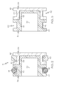
- Figure 2 is an enlarged cross-sectional view of the damper gas cup assembly of figure 1 removed from the damper of figure 1 ;
- Figure 3 is a view, as in figure 2 but with the first and second seals removed from the damper gas cup assembly.
- FIG. 1 shows an embodiment of the present invention.
- a first expression of the embodiment of figures 1-3 is for a damper 10 including a damper cylinder 12, a floating damper gas cup assembly 14, a damping fluid 16, a gas 18, a damper piston assembly 20, a piston rod 22, and a rod guide assembly 24.
- the damper cylinder 12 has a (monolithic or non-monolithic) closed end portion 26 and an open end portion 28.
- the damper gas cup assembly 14 is disposed in, and is slidingly engagable with, the damper cylinder 12 to create a first chamber 30 extending from the damper gas cup assembly 14 toward the open end portion 28 and a second chamber 32 extending from the damper gas cup assembly 14 toward the closed end portion 26.
- the damper gas cup assembly 14 includes a gas-and-liquid-impermeable damper gas cup 34 and a liquid-permeable member 36.
- the damper gas cup 34 has a central longitudinal axis 38 and has an outwardly-facing first circumferential surface 40 with a fully-circumferential first surface groove 42.
- the first surface groove 42 is adapted to receive a first seal 44.
- the member 36 is disposed outside, and is attached to, the damper gas cup 34 and has an outwardly-facing second circumferential surface 46 with a fully-circumferential second surface groove 48.
- the second surface groove 48 is adapted to receive a second seal 50.
- the damping fluid 16 is disposed within the first chamber 30 and is in contact with the member 36.
- the gas 18 (such as, but not limited to, air) is disposed within the second chamber 32 and is in contact with the damper gas cup 34.
- the damper piston assembly 20 is disposed within the first chamber 30 and is slidingly engagable with the damper cylinder 12.
- the piston rod 22 has a first end portion 52 which is attached to the damper piston assembly 20 and has a second end portion 54 which extends outside the open end portion 28 of the damper cylinder 12.
- the rod guide assembly 24 is attached to the open end portion 28 of the damper cylinder 12 and is adapted to guide the piston rod 22 and to seal the damping fluid 16 within the first chamber 30.
- circumferential surface is not limited to circular cylindrical surfaces for the purpose of describing any one or more or all of the expressions of the embodiment of figures 1-3 .
- a “circumferential surface” includes, for example and without limitation, a rectangular cylindrical surface.
- slidingly engagable with a damper cylinder includes a component being directly slidingly engagable with a damper cylinder and a component being indirectly slidingly engagable with a damper cylinder through an intervening seal.
- the damper gas cup assembly 14 includes the first seal 44 disposed in the first surface groove 42 and includes the second seal 50 disposed in the second surface groove 48, wherein the first and second seals (44 and 50) each are slidingly engagable with the damper cylinder (12).
- the first and second surface grooves 42 and 48 are substantially coaxially aligned with the longitudinal axis 38.
- the damping fluid 16 is a magnetorheological (MR) damping fluid
- the first seal 44 is a better gas seal than is the second seal 50.
- the second seal 50 is a better abrasion resistant seal than is the first seal 44.
- the first seal 44 comprises nitrile-butadiene rubber (NBR)
- the second seal 50 comprises polyurethane.
- the damper gas cup 34 includes a longitudinally-extending closed bottom portion 56 and a longitudinally extending open top portion 58, wherein the top portion 58 extends outward of the bottom portion 56, and wherein the top portion 58 includes the first surface groove 42.
- the member 36 is substantially coaxially aligned with the longitudinal axis 38, surrounds the bottom portion 56, and contacts the top portion 58.
- first surface groove 42 has an outwardly-facing first entrance 60, and the first surface groove 42 completely surrounds the first seal 44 except at the first entrance 60.
- second surface groove 48 has an outwardly-facing second entrance 62, and the second surface groove 48 completely surrounds the second seal 50 except at the second entrance 62.
- each circumferential surface 40 and 46 is a circular cylindrical surface.
- each circumferential surface 40 and 46 is a radially-outwardly-facing circumferential surface
- the top portion 58 extends radially outward of the bottom portion 56
- the surface grooves 42 and 48 have corresponding radially-outwardly-facing entrances 60 and 62.
- the damper piston assembly 20 includes a piston core and includes a piston ring disposed outward of the piston core to define a through passageway between the piston core and the piston ring.
- damper piston assemblies including damper piston assemblies having piston seals, are left to those skilled in the art.
- a second expression of the embodiment of figures 1-3 is for a damper gas cup assembly 14 including a gas-and-liquid-impermeable damper gas cup 34 and a liquid-permeable member 36.
- the damper gas cup 34 has a central longitudinal axis 38 and has an outwardly-facing first circumferential surface 40 with a fully-circumferential first surface groove 42.
- the first surface groove 42 is adapted to receive a first seal 44.
- the member 36 is disposed outside, and is attached to, the damper gas cup 34 and has an outwardly-facing second circumferential surface 46 with a fully-circumferential second surface groove 48.
- the second surface groove 48 is adapted to receive a second seal 50.
- the damper gas cup 34 has an over-molded attachment to the member 36.
- the damper gas cup 34 comprises a plastic
- the member 36 comprises one of a porous powdered metal and a porous ceramic.
- the damper gas cup 34 consists essentially of Nylon 66 with about a thirty-three percent glass fill
- the member 36 consists essentially of porous stainless steel powdered metal.
- a third expression of the embodiment of figures 1-3 is for a damper gas cup assembly 14 including a gas-and-liquid-impermeable damper gas cup 34, a liquid-permeable member 36, a first seal 44, and a second seal 50.
- the damper gas cup 34 has a central longitudinal axis 38 and has an outwardly-facing first circumferential surface 40 with a fully-circumferential first surface groove 42.
- the member 36 is disposed outside, and is attached to, the damper gas cup 34 and has an outwardly-facing second circumferential surface 46 with a fully-circumferential second surface groove 48.
- the first seal 44 is disposed in the first surface groove 42.
- the second seal 50 is disposed in the second surface groove 48.
- the liquid-permeable member provides an internal fluid path allowing the damping fluid to bypass the second seal which avoids the undesirable pumping action created between the two seals when two seals in series are conventionally employed on a component which is moved against a sealing surface, as can be appreciated by those skilled in the art.
- the damping fluid is an MR damping fluid containing, for example, abrasive iron particles
- the first seal can be a better gas seal than the second seal
- the second seal can be a better abrasion resistant seal then the first seal (rather than conventionally choosing one seal which compromises on meeting all sealing requirements).
- the liquid-permeable member will filter out the abrasive particles in the MR damping fluid supplying substantially particle-free damping fluid between the first and second seals providing clean lubrication without exposing the first seal to the abrasive particles, and the first seal will protect the second seal from the abrasive particles which encounter the first seal.
Landscapes
- Engineering & Computer Science (AREA)
- General Engineering & Computer Science (AREA)
- Mechanical Engineering (AREA)
- Fluid-Damping Devices (AREA)
Abstract
Description
- The present invention relates generally to piston dampers, and more particularly to a damper having a gas cup assembly and to a gas cup assembly for a damper.
- Conventional piston dampers include dampers having a tube, a piston assembly (such as a piston assembly including a piston core and a piston ring positioned outward of the piston core to define a through passageway between the piston core and the piston ring), and a piston rod. The tube contains a damping fluid. The piston assembly slideably engages the tube between the closed and open end portions of the tube. The piston rod has a first end portion attached to the piston assembly and a second end portion extending outside the open end portion of the tube. A rod guide assembly is attached to the open end portion of the tube to guide the piston rod and to seal the damping fluid within the tube. A floating, hermetically-sealing gas cup (such as one made of impermeable aluminum) slidingly engages the tube to separate the damping fluid from a gas and slides (floats) to adjust for the volume change caused by the moving piston rod, thermal expansion of the damping fluid, and normal loss of damping fluid, as is known to those skilled in the art. The gas cup has a single seal disposed in fully-circumferential surface groove on the outwardly-facing circumferential surface of the gas cup.
- Conventional piston dampers include magnetorheological (MR) dampers having MR damping fluid and non-MR dampers having non-MR damping fluid (such as hydraulic fluid). The MR fluid, which typically is hydraulic fluid containing iron particles, passes through an MR passageway (i.e., a magnetically energizable passageway) of the MR piston assembly. Exposing the MR fluid in the MR passageway to a varying magnetic field, generated by providing a varying electric current to an electric coil of the MR piston assembly, varies the damping effect of the MR fluid in the MR passageway providing variably-controlled damping of relative motion between the MR piston assembly and the tube. The electric current is varied (including turning off the electric current) to accommodate varying operating conditions, as is known to those skilled in the art. The seal for the gas cup of a monotube MR damper comes down to a choice of seal materials such as a polyurethane seal (for better abrasion resistance to the typically iron particles in the MR fluid) or an HNBR (Hydrogenated Nitrile Butadiene Rubber) seal (for better high temperature and gas sealing properties).
- What is needed is an improved gas cup assembly and an improved damper having a gas cup assembly.
- A first expression of an embodiment of the invention is for a damper including a damper cylinder, a floating damper gas cup assembly, a damping fluid, a gas, a damper piston assembly, a piston rod, and a rod guide assembly. The damper cylinder has a closed end portion and an open end portion. The damper gas cup assembly is disposed in, and is slidingly engagable with, the damper cylinder to create a first chamber extending from the damper gas cup assembly toward the open end portion and a second chamber extending from the damper gas cup assembly toward the closed end portion. The damper gas cup assembly includes a gas-and-liquid-impermeable damper gas cup and a liquid-permeable member. The damper gas cup has a central longitudinal axis and has an outwardly-facing first circumferential surface with a fully-circumferential first surface groove. The first surface groove is adapted to receive a first seal. The member is disposed outside, and is attached to, the damper gas cup and has an outwardly-facing second circumferential surface with a fully-circumferential second surface groove. The second surface groove is adapted to receive a second seal. The damping fluid is disposed within the first chamber and is in contact with the member. The gas is disposed within the second chamber and is in contact with the damper gas cup. The damper piston assembly is disposed within the first chamber and is slidingly engagable with the damper cylinder. The piston rod has a first end portion which is attached to the damper piston assembly and has a second end portion which extends outside the open end portion of the damper cylinder. The rod guide assembly is attached to the open end portion of the damper cylinder and is adapted to guide the piston rod and to seal the damping fluid within the first chamber.
- A second expression of an embodiment of the invention is for a damper gas cup assembly including a gas-and-liquid-impermeable damper gas cup and a liquid-permeable member. The damper gas cup has a central longitudinal axis and has an outwardly-facing first circumferential surface with a fully-circumferential first surface groove. The first surface groove is adapted to receive a first seal. The member is disposed outside, and is attached to, the damper gas cup and has an outwardly-facing second circumferential surface with a fully-circumferential second surface groove. The second surface groove is adapted to receive a second seal.
- A third expression of an embodiment of the invention is for a damper gas cup assembly including a gas-and-liquid-impermeable damper gas cup, a liquid-permeable member, a first seal, and a second seal. The damper gas cup has a central longitudinal axis and has an outwardly-facing first circumferential surface with a fully-circumferential first surface groove. The member is disposed outside, and is attached to, the damper gas cup and has an outwardly-facing second circumferential surface with a fully-circumferential second surface groove. The first seal is disposed in the first surface groove. The second seal is disposed in the second surface groove.
- Several benefits and advantages are derived from one or more of the expressions of the embodiment of the invention. In one example, the liquid-permeable member provides an internal fluid path allowing the damping fluid to bypass the second seal which avoids the undesirable pumping action created between the two seals when two seals in series are conventionally employed on a component which is moved against a sealing surface, as can be appreciated by those skilled in the art. In the same or a different example, when the damping fluid is an MR damping fluid containing, for example, abrasive iron particles, the first seal can be a better gas seal than the second seal, and the second seal can be a better abrasion resistant seal then the first seal (rather than conventionally choosing one seal which compromises on meeting all sealing requirements). In this example, the liquid-permeable member will filter out the abrasive particles in the MR damping fluid supplying substantially particle-free damping fluid between the first and second seals providing clean lubrication without exposing the first seal to the abrasive particles, and the first seal will protect the second seal from the abrasive particles which encounter the first seal. This should, in this example, improve the durability of the gas cup assembly and may even allow the design clearance between the damper piston and the damper gas cup to be reduced (resulting in a shorter damper requiring less relatively expensive MR damping fluid), as can be appreciated by those skilled in the art.
-
Figure 1 is a schematic, cross-sectional view of an embodiment of the invention showing a damper which includes a damper gas cup assembly; -
Figure 2 is an enlarged cross-sectional view of the damper gas cup assembly offigure 1 removed from the damper offigure 1 ; and -
Figure 3 is a view, as infigure 2 but with the first and second seals removed from the damper gas cup assembly. - Referring now to the drawings,
figures 1-3 show an embodiment of the present invention. A first expression of the embodiment offigures 1-3 is for a damper 10 including adamper cylinder 12, a floating dampergas cup assembly 14, adamping fluid 16, agas 18, a damper piston assembly 20, a piston rod 22, and a rod guide assembly 24. Thedamper cylinder 12 has a (monolithic or non-monolithic) closedend portion 26 and an open end portion 28. The dampergas cup assembly 14 is disposed in, and is slidingly engagable with, thedamper cylinder 12 to create afirst chamber 30 extending from the dampergas cup assembly 14 toward the open end portion 28 and asecond chamber 32 extending from the dampergas cup assembly 14 toward the closedend portion 26. The dampergas cup assembly 14 includes a gas-and-liquid-impermeabledamper gas cup 34 and a liquid-permeable member 36. Thedamper gas cup 34 has a centrallongitudinal axis 38 and has an outwardly-facing firstcircumferential surface 40 with a fully-circumferentialfirst surface groove 42. Thefirst surface groove 42 is adapted to receive afirst seal 44. Themember 36 is disposed outside, and is attached to, thedamper gas cup 34 and has an outwardly-facing secondcircumferential surface 46 with a fully-circumferentialsecond surface groove 48. Thesecond surface groove 48 is adapted to receive asecond seal 50. Thedamping fluid 16 is disposed within thefirst chamber 30 and is in contact with themember 36. The gas 18 (such as, but not limited to, air) is disposed within thesecond chamber 32 and is in contact with thedamper gas cup 34. The damper piston assembly 20 is disposed within thefirst chamber 30 and is slidingly engagable with thedamper cylinder 12. The piston rod 22 has a first end portion 52 which is attached to the damper piston assembly 20 and has a second end portion 54 which extends outside the open end portion 28 of thedamper cylinder 12. The rod guide assembly 24 is attached to the open end portion 28 of thedamper cylinder 12 and is adapted to guide the piston rod 22 and to seal thedamping fluid 16 within thefirst chamber 30. - It is noted that the terminology "circumferential surface" is not limited to circular cylindrical surfaces for the purpose of describing any one or more or all of the expressions of the embodiment of
figures 1-3 . A "circumferential surface" includes, for example and without limitation, a rectangular cylindrical surface. It also is noted that the terminology "slidingly engagable with a damper cylinder" includes a component being directly slidingly engagable with a damper cylinder and a component being indirectly slidingly engagable with a damper cylinder through an intervening seal. - In one enablement of the first expression of the embodiment of
figures 1-3 , the dampergas cup assembly 14 includes thefirst seal 44 disposed in thefirst surface groove 42 and includes thesecond seal 50 disposed in thesecond surface groove 48, wherein the first and second seals (44 and 50) each are slidingly engagable with the damper cylinder (12). In one variation, the first andsecond surface grooves longitudinal axis 38. - In one implementation of the enablement, the damping
fluid 16 is a magnetorheological (MR) damping fluid, and thefirst seal 44 is a better gas seal than is thesecond seal 50. In one variation, thesecond seal 50 is a better abrasion resistant seal than is thefirst seal 44. In one choice of materials, thefirst seal 44 comprises nitrile-butadiene rubber (NBR), and thesecond seal 50 comprises polyurethane. In one modification, thedamper gas cup 34 includes a longitudinally-extendingclosed bottom portion 56 and a longitudinally extending opentop portion 58, wherein thetop portion 58 extends outward of thebottom portion 56, and wherein thetop portion 58 includes thefirst surface groove 42. In one arrangement, themember 36 is substantially coaxially aligned with thelongitudinal axis 38, surrounds thebottom portion 56, and contacts thetop portion 58. - In the same or a different implementation,
first surface groove 42 has an outwardly-facingfirst entrance 60, and thefirst surface groove 42 completely surrounds thefirst seal 44 except at thefirst entrance 60. In the same or a different implementation, thesecond surface groove 48 has an outwardly-facingsecond entrance 62, and thesecond surface groove 48 completely surrounds thesecond seal 50 except at thesecond entrance 62. - In a first configuration of the first expression of the embodiment of
figures 1-3 , eachcircumferential surface circumferential surface top portion 58 extends radially outward of thebottom portion 56, and thesurface grooves entrances - A second expression of the embodiment of
figures 1-3 is for a dampergas cup assembly 14 including a gas-and-liquid-impermeabledamper gas cup 34 and a liquid-permeable member 36. Thedamper gas cup 34 has a centrallongitudinal axis 38 and has an outwardly-facing firstcircumferential surface 40 with a fully-circumferentialfirst surface groove 42. Thefirst surface groove 42 is adapted to receive afirst seal 44. Themember 36 is disposed outside, and is attached to, thedamper gas cup 34 and has an outwardly-facing secondcircumferential surface 46 with a fully-circumferentialsecond surface groove 48. Thesecond surface groove 48 is adapted to receive asecond seal 50. - It is noted that the enablements, implementations, etc. of the first expression of the embodiment of
figures 1-3 are equally applicable to the second expression of the embodiment offigures 1-3 . In one construction of the second expression of the embodiment offigures 1-3 , thedamper gas cup 34 has an over-molded attachment to themember 36. In one choice of materials, thedamper gas cup 34 comprises a plastic, and themember 36 comprises one of a porous powdered metal and a porous ceramic. In one example, thedamper gas cup 34 consists essentially of Nylon 66 with about a thirty-three percent glass fill, and themember 36 consists essentially of porous stainless steel powdered metal. - A third expression of the embodiment of
figures 1-3 is for a dampergas cup assembly 14 including a gas-and-liquid-impermeabledamper gas cup 34, a liquid-permeable member 36, afirst seal 44, and asecond seal 50. Thedamper gas cup 34 has a centrallongitudinal axis 38 and has an outwardly-facing firstcircumferential surface 40 with a fully-circumferentialfirst surface groove 42. Themember 36 is disposed outside, and is attached to, thedamper gas cup 34 and has an outwardly-facing secondcircumferential surface 46 with a fully-circumferentialsecond surface groove 48. Thefirst seal 44 is disposed in thefirst surface groove 42. Thesecond seal 50 is disposed in thesecond surface groove 48. - It is noted that the enablements, implementations, constructions, examples, etc. of the first and second expressions of the embodiment of
figures 1-3 are equally applicable to the third expression of the embodiment offigures 1-3 . - Several benefits and advantages are derived from one or more of the expressions of the embodiment of the invention. In one example, the liquid-permeable member provides an internal fluid path allowing the damping fluid to bypass the second seal which avoids the undesirable pumping action created between the two seals when two seals in series are conventionally employed on a component which is moved against a sealing surface, as can be appreciated by those skilled in the art. In the same or a different example, when the damping fluid is an MR damping fluid containing, for example, abrasive iron particles, the first seal can be a better gas seal than the second seal, and the second seal can be a better abrasion resistant seal then the first seal (rather than conventionally choosing one seal which compromises on meeting all sealing requirements). In this example, the liquid-permeable member will filter out the abrasive particles in the MR damping fluid supplying substantially particle-free damping fluid between the first and second seals providing clean lubrication without exposing the first seal to the abrasive particles, and the first seal will protect the second seal from the abrasive particles which encounter the first seal. This should, in this example, improve the durability of the gas cup assembly and may even allow the design clearance between the damper piston and the damper gas cup to be reduced (resulting in a shorter damper requiring less relatively expensive MR damping fluid), as can be appreciated by those skilled in the art.
- The foregoing description of several expressions of an embodiment of the invention has been presented for purposes of illustration. It is not intended to be exhaustive or to limit the invention to the precise form disclosed, and obviously many modifications and variations are possible in light of the above teaching. It is intended that the scope of the invention be defined by the claims appended hereto.
Claims (20)
- A damper (10) comprising:a) a damper cylinder (12) having a closed end portion (26) and an open end portion (28);b) a floating damper gas cup assembly (14) disposed in, and slidingly engagable with, the damper cylinder (12) to create a first chamber (30) extending from the damper gas cup assembly (14) toward the open end portion (28) and a second chamber (32) extending from the damper gas cup assembly (14) toward the closed end portion (26), wherein the damper gas cup assembly (14) includes:(1) a gas-and-liquid-impermeable damper gas cup (34) having a central longitudinal axis (38) and having an outwardly-facing first circumferential surface (40) with a fully-circumferential first surface groove (42), wherein the first surface groove (42) is adapted to receive a first seal (44); and(2) a liquid-permeable member (36) disposed outside, and attached to, the damper gas cup (34) and having an outwardly-facing second circumferential surface (46) with a fully-circumferential second surface groove (48), wherein the second surface groove (48) is adapted to receive a second seal (50);c) a damping fluid (16) disposed within the first chamber (30) and in contact with the member (36);d) a gas (18) disposed within the second chamber (32) and in contact with the damper gas cup (34);e) a damper piston assembly (20) disposed within the first chamber (30) and slidingly engagable with the damper cylinder (12);f) a piston rod (22) having a first end portion (52) attached to the damper piston assembly (20) and a second end portion (54) extending outside the open end portion (28) of the damper cylinder (12); andg) a rod guide assembly (24) attached to the open end portion (28) of the damper cylinder (12) and adapted to guide the piston rod (22) and to seal the damping fluid (16) within the first chamber (30).
- The damper (10) of claim 1, wherein the damper gas cup assembly (14) includes the first seal (44) disposed in the first surface groove (42) and includes the second seal (50) disposed in the second surface groove (48), wherein the first and second seals (44 and 50) each are slidingly engagable with the damper cylinder (12).
- The damper (10) of claim 2, wherein the damping fluid (16) is a magnetorheological (MR) damping fluid, and wherein the first seal (44) is a better gas seal than is the second seal (50).
- The damper (10) of claim 3, wherein the second seal (50) is a better abrasion resistant seal than is the first seal (44).
- The damper (10) of claim 4, wherein the first seal (44) comprises nitrile-butadiene rubber, and wherein the second seal (50) comprises polyurethane.
- The damper (10) of claim 4, wherein the damper gas cup (34) includes a longitudinally-extending closed bottom portion (56) and a longitudinally extending open top portion (58), wherein the top portion (58) extends outward of the bottom portion (56), and wherein the top portion (58) includes the first surface groove (42).
- The damper (10) of claim 6, wherein the member (36) is substantially coaxially aligned with the longitudinal axis (38), surrounds the bottom portion (56), and contacts the top portion (58).
- The damper (10) of claim 2, wherein first surface groove (42) has an outwardly-facing first entrance (60), and wherein the first surface groove (42) completely surrounds the first seal (44) except at the first entrance (60).
- The damper (10) of claim 2, wherein second surface groove (48) has an outwardly-facing second entrance (62), and wherein the second surface groove (48) completely surrounds the second seal (50) except at the second entrance (62).
- A damper gas cup assembly (14) comprising:a) a gas-and-liquid-impermeable damper gas cup (34) having a central longitudinal axis (38) and having an outwardly-facing first circumferential surface (40) with a fully-circumferential first surface groove (42), wherein the first surface groove (42) is adapted to receive a first seal (44); andb) a liquid-permeable member (36) disposed outside, and attached to, the damper gas cup (34) and having an outwardly-facing second circumferential surface (46) with a fully-circumferential second surface groove (48), wherein the second surface groove (48) is adapted to receive a second seal (50).
- The damper gas cup assembly (14) of claim 10, wherein the damper gas cup (34) has an over-molded attachment to the member (36).
- The damper gas cup assembly (14) of claim 11, wherein the damper gas cup (34) comprises a plastic, and wherein the member (36) comprises one of a porous powdered metal and a porous ceramic.
- A damper gas cup assembly (14) comprising:a) a gas-and-liquid-impermeable damper gas cup (34) having a central longitudinal axis (38) and having an outwardly-facing first circumferential surface (40) with a fully-circumferential first surface groove (42);b) a liquid-permeable member (36) disposed outside, and attached to, the damper gas cup (34) and having an outwardly-facing second circumferential surface (46) with a fully-circumferential second surface groove (48);c) a first seal (44) disposed in the first surface groove (42); andd) a second seal (50) disposed in the second surface groove (48).
- The damper gas cup assembly (14) of claim 13, wherein the damping fluid (16) is a magnetorheological (MR) damping fluid, and wherein the first seal (44) is a better gas seal than is the second seal (50).
- The damper gas cup assembly (14) of claim 14, wherein the second seal (50) is a better abrasion resistant seal than is the first seal (44).
- The damper gas cup assembly (14) of claim 15, wherein the first seal (44) comprises nitrile-butadiene rubber, and wherein the second seal (50) comprises polyurethane.
- The damper gas cup assembly (14) of claim 13, wherein the damper gas cup (34) includes a longitudinally-extending closed bottom portion (56) and a longitudinally extending open top portion (58), wherein the top portion (58) extends outward of the bottom portion (56), and wherein the top portion (58) includes the first surface groove (42).
- The damper gas cup assembly (14) of claim 17, wherein the member (36) is substantially coaxially aligned with the longitudinal axis (38), surrounds the bottom portion (56), and contacts the top portion (58).
- The damper gas cup assembly (14) of claim 13, wherein first surface groove (42) has an outwardly-facing first entrance (60), and wherein the first surface groove (42) completely surrounds the first seal (44) except at the first entrance (60).
- The damper gas cup assembly (14) of claim 13, wherein second surface groove (48) has an outwardly-facing second entrance (62), and wherein the second surface groove (48) completely surrounds the second seal (50) except at the second entrance (62).
Applications Claiming Priority (2)
| Application Number | Priority Date | Filing Date | Title |
|---|---|---|---|
| US93655007P | 2007-06-20 | 2007-06-20 | |
| US12/150,010 US20080314706A1 (en) | 2007-06-20 | 2008-04-24 | Gas cup assembly and damper having same |
Publications (3)
| Publication Number | Publication Date |
|---|---|
| EP2006567A2 true EP2006567A2 (en) | 2008-12-24 |
| EP2006567A3 EP2006567A3 (en) | 2016-04-13 |
| EP2006567B1 EP2006567B1 (en) | 2017-09-13 |
Family
ID=39772969
Family Applications (1)
| Application Number | Title | Priority Date | Filing Date |
|---|---|---|---|
| EP08157071.5A Ceased EP2006567B1 (en) | 2007-06-20 | 2008-05-28 | Gas cup assembly and damper having same |
Country Status (2)
| Country | Link |
|---|---|
| US (1) | US20080314706A1 (en) |
| EP (1) | EP2006567B1 (en) |
Cited By (1)
| Publication number | Priority date | Publication date | Assignee | Title |
|---|---|---|---|---|
| CN117212337A (en) * | 2018-06-11 | 2023-12-12 | 特灵国际有限公司 | porous gas bearings |
Families Citing this family (33)
| Publication number | Priority date | Publication date | Assignee | Title |
|---|---|---|---|---|
| US10060499B2 (en) | 2009-01-07 | 2018-08-28 | Fox Factory, Inc. | Method and apparatus for an adjustable damper |
| US20120305350A1 (en) | 2011-05-31 | 2012-12-06 | Ericksen Everet O | Methods and apparatus for position sensitive suspension damping |
| US10047817B2 (en) | 2009-01-07 | 2018-08-14 | Fox Factory, Inc. | Method and apparatus for an adjustable damper |
| US9452654B2 (en) | 2009-01-07 | 2016-09-27 | Fox Factory, Inc. | Method and apparatus for an adjustable damper |
| US8857580B2 (en) | 2009-01-07 | 2014-10-14 | Fox Factory, Inc. | Remotely operated bypass for a suspension damper |
| US9033122B2 (en) | 2009-01-07 | 2015-05-19 | Fox Factory, Inc. | Method and apparatus for an adjustable damper |
| US20100170760A1 (en) | 2009-01-07 | 2010-07-08 | John Marking | Remotely Operated Bypass for a Suspension Damper |
| US8627932B2 (en) | 2009-01-07 | 2014-01-14 | Fox Factory, Inc. | Bypass for a suspension damper |
| US11306798B2 (en) | 2008-05-09 | 2022-04-19 | Fox Factory, Inc. | Position sensitive suspension damping with an active valve |
| US8393446B2 (en) | 2008-08-25 | 2013-03-12 | David M Haugen | Methods and apparatus for suspension lock out and signal generation |
| US9422018B2 (en) | 2008-11-25 | 2016-08-23 | Fox Factory, Inc. | Seat post |
| US12491961B2 (en) | 2008-11-25 | 2025-12-09 | Fox Factory, Inc. | Seat post |
| US10036443B2 (en) | 2009-03-19 | 2018-07-31 | Fox Factory, Inc. | Methods and apparatus for suspension adjustment |
| US9140325B2 (en) | 2009-03-19 | 2015-09-22 | Fox Factory, Inc. | Methods and apparatus for selective spring pre-load adjustment |
| US9038791B2 (en) | 2009-01-07 | 2015-05-26 | Fox Factory, Inc. | Compression isolator for a suspension damper |
| US10821795B2 (en) | 2009-01-07 | 2020-11-03 | Fox Factory, Inc. | Method and apparatus for an adjustable damper |
| US12122205B2 (en) | 2009-01-07 | 2024-10-22 | Fox Factory, Inc. | Active valve for an internal bypass |
| US11299233B2 (en) | 2009-01-07 | 2022-04-12 | Fox Factory, Inc. | Method and apparatus for an adjustable damper |
| US8936139B2 (en) | 2009-03-19 | 2015-01-20 | Fox Factory, Inc. | Methods and apparatus for suspension adjustment |
| US8672106B2 (en) | 2009-10-13 | 2014-03-18 | Fox Factory, Inc. | Self-regulating suspension |
| EP2312180B1 (en) | 2009-10-13 | 2019-09-18 | Fox Factory, Inc. | Apparatus for controlling a fluid damper |
| US10697514B2 (en) | 2010-01-20 | 2020-06-30 | Fox Factory, Inc. | Remotely operated bypass for a suspension damper |
| EP3778358B1 (en) | 2010-07-02 | 2023-04-12 | Fox Factory, Inc. | Positive lock adjustable seat post |
| GB2489271A (en) * | 2011-03-23 | 2012-09-26 | Vistamatic Ltd | A miniature damper, a viewing panel, and an installation method |
| EP3567272B1 (en) | 2011-09-12 | 2021-05-26 | Fox Factory, Inc. | Methods and apparatus for suspension set up |
| US11279199B2 (en) | 2012-01-25 | 2022-03-22 | Fox Factory, Inc. | Suspension damper with by-pass valves |
| US10330171B2 (en) | 2012-05-10 | 2019-06-25 | Fox Factory, Inc. | Method and apparatus for an adjustable damper |
| EP3039313B1 (en) * | 2013-08-27 | 2019-01-09 | BeijingWest Industries Co., Ltd. | Monotube damper assembly |
| JP6212337B2 (en) * | 2013-09-13 | 2017-10-11 | Kyb株式会社 | Single cylinder type hydraulic shock absorber |
| DE102014203077A1 (en) * | 2014-02-20 | 2015-08-20 | Zf Friedrichshafen Ag | Separating piston for a vibration damper |
| SE1450765A1 (en) | 2014-06-19 | 2015-12-20 | Strömsholmen Ab | Gas spring and safety procedure for gas spring |
| US10737546B2 (en) | 2016-04-08 | 2020-08-11 | Fox Factory, Inc. | Electronic compression and rebound control |
| US11668364B2 (en) * | 2020-11-25 | 2023-06-06 | Beijingwest Industries Co., Ltd | Gas cup for a damper assembly and a damper assembly |
Family Cites Families (10)
| Publication number | Priority date | Publication date | Assignee | Title |
|---|---|---|---|---|
| US3101131A (en) * | 1960-11-07 | 1963-08-20 | Bourcier Carbon Previnquieres | Hydraulic pneumatic shock absorber |
| GB1206752A (en) * | 1966-11-17 | 1970-09-30 | Girling Ltd | Improvements in or relating to pressurised telescopic dampers |
| DE3020840A1 (en) * | 1980-04-14 | 1981-10-15 | Schweizerische Aluminium AG, 3965 Chippis | SHOCK ABSORBER |
| US4560174A (en) * | 1983-12-02 | 1985-12-24 | Berco S.P.A. | Multi lip seal |
| JPS6319434A (en) * | 1986-07-10 | 1988-01-27 | Nifco Inc | Elastic oil damper |
| DE19834092C2 (en) * | 1998-07-29 | 2003-04-30 | Continental Ag | Air strut and method of manufacturing an air strut |
| US20020130002A1 (en) * | 2001-03-15 | 2002-09-19 | Delphi Technologies, Inc. | Gas cup seal for magneto-rheological damper |
| US6419058B1 (en) * | 2001-03-30 | 2002-07-16 | Delphi Technologies, Inc. | Magnetorheological damper with piston bypass |
| US6883649B2 (en) * | 2003-03-21 | 2005-04-26 | Delphi Technologies, Inc. | Closing system for a magneto-rheological damper |
| DE10350431B3 (en) * | 2003-10-29 | 2005-03-10 | Zahnradfabrik Friedrichshafen | Damper with separating piston for damping vibrations has one seal in form of scraper with chamber to take dirt out of working cavity |
-
2008
- 2008-04-24 US US12/150,010 patent/US20080314706A1/en not_active Abandoned
- 2008-05-28 EP EP08157071.5A patent/EP2006567B1/en not_active Ceased
Non-Patent Citations (1)
| Title |
|---|
| None |
Cited By (1)
| Publication number | Priority date | Publication date | Assignee | Title |
|---|---|---|---|---|
| CN117212337A (en) * | 2018-06-11 | 2023-12-12 | 特灵国际有限公司 | porous gas bearings |
Also Published As
| Publication number | Publication date |
|---|---|
| EP2006567A3 (en) | 2016-04-13 |
| EP2006567B1 (en) | 2017-09-13 |
| US20080314706A1 (en) | 2008-12-25 |
Similar Documents
| Publication | Publication Date | Title |
|---|---|---|
| EP2006567B1 (en) | Gas cup assembly and damper having same | |
| EP2093455B1 (en) | Magnetorheological (MR) rod guide assembly and MR damper having same | |
| TWI398588B (en) | Balanced solenoid valve | |
| KR101639506B1 (en) | Damping valve of buffer | |
| KR101429577B1 (en) | Balanced poppet-type electromagnetic valve | |
| CN108291603B (en) | Damper | |
| US20140008557A1 (en) | Solenoid valve with flat core and flat spring | |
| EP1245855A2 (en) | Magnetorheological damper with piston bypass | |
| EP2884061B1 (en) | A gasket for a valve of an internal combustion engine | |
| JPH05248545A (en) | Valve stem seal assembly | |
| CN107771255A (en) | The hydraulic compression stopper element of the hydraulic damper for vehicle suspension with decompressor | |
| KR20150113885A (en) | Damping force adjustable damper | |
| US20210033165A1 (en) | Magnetorheological hydraulic damper with passive damping chamber | |
| EP3324074A1 (en) | Dual mode hydraulic damper | |
| US9353821B2 (en) | Fluid damper assembly with gas cup lubrication chamber | |
| US9388913B2 (en) | Seal and control device having said seal | |
| EP2902682A1 (en) | Pilot-operated valve with floating piston | |
| US20090277733A1 (en) | Kolben-Zylinderaggregat | |
| JP2014105754A (en) | Solenoid valve device for high pressure fluid | |
| EP1355081A1 (en) | Shock absorber | |
| US20100116607A1 (en) | Dual seal rod guide assembly with low friction disc | |
| US20170350464A1 (en) | Shock absorber | |
| CN105190139A (en) | Overflow valve | |
| KR102554152B1 (en) | Damping force adjustable shock absorber | |
| US20080115663A1 (en) | Vibration damper with amplitude-selective damping force |
Legal Events
| Date | Code | Title | Description |
|---|---|---|---|
| PUAI | Public reference made under article 153(3) epc to a published international application that has entered the european phase |
Free format text: ORIGINAL CODE: 0009012 |
|
| AK | Designated contracting states |
Kind code of ref document: A2 Designated state(s): AT BE BG CH CY CZ DE DK EE ES FI FR GB GR HR HU IE IS IT LI LT LU LV MC MT NL NO PL PT RO SE SI SK TR |
|
| AX | Request for extension of the european patent |
Extension state: AL BA MK RS |
|
| RAP1 | Party data changed (applicant data changed or rights of an application transferred) |
Owner name: BWI COMPANY LIMITED S.A. |
|
| PUAL | Search report despatched |
Free format text: ORIGINAL CODE: 0009013 |
|
| AK | Designated contracting states |
Kind code of ref document: A3 Designated state(s): AT BE BG CH CY CZ DE DK EE ES FI FR GB GR HR HU IE IS IT LI LT LU LV MC MT NL NO PL PT RO SE SI SK TR |
|
| AX | Request for extension of the european patent |
Extension state: AL BA MK RS |
|
| RIC1 | Information provided on ipc code assigned before grant |
Ipc: F16F 9/06 20060101AFI20160310BHEP |
|
| 17P | Request for examination filed |
Effective date: 20161010 |
|
| RBV | Designated contracting states (corrected) |
Designated state(s): AT BE BG CH CY CZ DE DK EE ES FI FR GB GR HR HU IE IS IT LI LT LU LV MC MT NL NO PL PT RO SE SI SK TR |
|
| AKX | Designation fees paid |
Designated state(s): DE FR GB |
|
| AXX | Extension fees paid |
Extension state: MK Extension state: RS Extension state: AL Extension state: BA |
|
| GRAP | Despatch of communication of intention to grant a patent |
Free format text: ORIGINAL CODE: EPIDOSNIGR1 |
|
| INTG | Intention to grant announced |
Effective date: 20170425 |
|
| GRAS | Grant fee paid |
Free format text: ORIGINAL CODE: EPIDOSNIGR3 |
|
| GRAA | (expected) grant |
Free format text: ORIGINAL CODE: 0009210 |
|
| AK | Designated contracting states |
Kind code of ref document: B1 Designated state(s): DE FR GB |
|
| REG | Reference to a national code |
Ref country code: GB Ref legal event code: FG4D |
|
| REG | Reference to a national code |
Ref country code: DE Ref legal event code: R096 Ref document number: 602008052084 Country of ref document: DE |
|
| REG | Reference to a national code |
Ref country code: FR Ref legal event code: PLFP Year of fee payment: 11 |
|
| REG | Reference to a national code |
Ref country code: DE Ref legal event code: R097 Ref document number: 602008052084 Country of ref document: DE |
|
| PLBE | No opposition filed within time limit |
Free format text: ORIGINAL CODE: 0009261 |
|
| STAA | Information on the status of an ep patent application or granted ep patent |
Free format text: STATUS: NO OPPOSITION FILED WITHIN TIME LIMIT |
|
| 26N | No opposition filed |
Effective date: 20180614 |
|
| PGFP | Annual fee paid to national office [announced via postgrant information from national office to epo] |
Ref country code: GB Payment date: 20220407 Year of fee payment: 15 Ref country code: FR Payment date: 20220408 Year of fee payment: 15 Ref country code: DE Payment date: 20220406 Year of fee payment: 15 |
|
| REG | Reference to a national code |
Ref country code: DE Ref legal event code: R119 Ref document number: 602008052084 Country of ref document: DE |
|
| GBPC | Gb: european patent ceased through non-payment of renewal fee |
Effective date: 20230528 |
|
| PG25 | Lapsed in a contracting state [announced via postgrant information from national office to epo] |
Ref country code: DE Free format text: LAPSE BECAUSE OF NON-PAYMENT OF DUE FEES Effective date: 20231201 Ref country code: GB Free format text: LAPSE BECAUSE OF NON-PAYMENT OF DUE FEES Effective date: 20230528 |
|
| PG25 | Lapsed in a contracting state [announced via postgrant information from national office to epo] |
Ref country code: FR Free format text: LAPSE BECAUSE OF NON-PAYMENT OF DUE FEES Effective date: 20230531 |