EP2006503A1 - Liquid tank, breather device for the liquid tank, and exhaust gas purification device for engine - Google Patents
Liquid tank, breather device for the liquid tank, and exhaust gas purification device for engine Download PDFInfo
- Publication number
- EP2006503A1 EP2006503A1 EP07714396A EP07714396A EP2006503A1 EP 2006503 A1 EP2006503 A1 EP 2006503A1 EP 07714396 A EP07714396 A EP 07714396A EP 07714396 A EP07714396 A EP 07714396A EP 2006503 A1 EP2006503 A1 EP 2006503A1
- Authority
- EP
- European Patent Office
- Prior art keywords
- vent hole
- liquid
- liquid tank
- main body
- tank main
- Prior art date
- Legal status (The legal status is an assumption and is not a legal conclusion. Google has not performed a legal analysis and makes no representation as to the accuracy of the status listed.)
- Granted
Links
Images


Classifications
-
- F—MECHANICAL ENGINEERING; LIGHTING; HEATING; WEAPONS; BLASTING
- F01—MACHINES OR ENGINES IN GENERAL; ENGINE PLANTS IN GENERAL; STEAM ENGINES
- F01N—GAS-FLOW SILENCERS OR EXHAUST APPARATUS FOR MACHINES OR ENGINES IN GENERAL; GAS-FLOW SILENCERS OR EXHAUST APPARATUS FOR INTERNAL-COMBUSTION ENGINES
- F01N3/00—Exhaust or silencing apparatus having means for purifying, rendering innocuous, or otherwise treating exhaust
- F01N3/08—Exhaust or silencing apparatus having means for purifying, rendering innocuous, or otherwise treating exhaust for rendering innocuous
- F01N3/10—Exhaust or silencing apparatus having means for purifying, rendering innocuous, or otherwise treating exhaust for rendering innocuous by thermal or catalytic conversion of noxious components of exhaust
- F01N3/18—Exhaust or silencing apparatus having means for purifying, rendering innocuous, or otherwise treating exhaust for rendering innocuous by thermal or catalytic conversion of noxious components of exhaust characterised by methods of operation; Control
- F01N3/20—Exhaust or silencing apparatus having means for purifying, rendering innocuous, or otherwise treating exhaust for rendering innocuous by thermal or catalytic conversion of noxious components of exhaust characterised by methods of operation; Control specially adapted for catalytic conversion
- F01N3/206—Adding periodically or continuously substances to exhaust gases for promoting purification, e.g. catalytic material in liquid form, NOx reducing agents
- F01N3/2066—Selective catalytic reduction [SCR]
-
- B—PERFORMING OPERATIONS; TRANSPORTING
- B60—VEHICLES IN GENERAL
- B60K—ARRANGEMENT OR MOUNTING OF PROPULSION UNITS OR OF TRANSMISSIONS IN VEHICLES; ARRANGEMENT OR MOUNTING OF PLURAL DIVERSE PRIME-MOVERS IN VEHICLES; AUXILIARY DRIVES FOR VEHICLES; INSTRUMENTATION OR DASHBOARDS FOR VEHICLES; ARRANGEMENTS IN CONNECTION WITH COOLING, AIR INTAKE, GAS EXHAUST OR FUEL SUPPLY OF PROPULSION UNITS IN VEHICLES
- B60K15/00—Arrangement in connection with fuel supply of combustion engines or other fuel consuming energy converters, e.g. fuel cells; Mounting or construction of fuel tanks
- B60K15/03—Fuel tanks
- B60K15/035—Fuel tanks characterised by venting means
- B60K15/03504—Fuel tanks characterised by venting means adapted to avoid loss of fuel or fuel vapour, e.g. with vapour recovery systems
-
- F—MECHANICAL ENGINEERING; LIGHTING; HEATING; WEAPONS; BLASTING
- F01—MACHINES OR ENGINES IN GENERAL; ENGINE PLANTS IN GENERAL; STEAM ENGINES
- F01N—GAS-FLOW SILENCERS OR EXHAUST APPARATUS FOR MACHINES OR ENGINES IN GENERAL; GAS-FLOW SILENCERS OR EXHAUST APPARATUS FOR INTERNAL-COMBUSTION ENGINES
- F01N2610/00—Adding substances to exhaust gases
- F01N2610/01—Adding substances to exhaust gases the substance being catalytic material in liquid form
-
- F—MECHANICAL ENGINEERING; LIGHTING; HEATING; WEAPONS; BLASTING
- F01—MACHINES OR ENGINES IN GENERAL; ENGINE PLANTS IN GENERAL; STEAM ENGINES
- F01N—GAS-FLOW SILENCERS OR EXHAUST APPARATUS FOR MACHINES OR ENGINES IN GENERAL; GAS-FLOW SILENCERS OR EXHAUST APPARATUS FOR INTERNAL-COMBUSTION ENGINES
- F01N2610/00—Adding substances to exhaust gases
- F01N2610/02—Adding substances to exhaust gases the substance being ammonia or urea
-
- F—MECHANICAL ENGINEERING; LIGHTING; HEATING; WEAPONS; BLASTING
- F01—MACHINES OR ENGINES IN GENERAL; ENGINE PLANTS IN GENERAL; STEAM ENGINES
- F01N—GAS-FLOW SILENCERS OR EXHAUST APPARATUS FOR MACHINES OR ENGINES IN GENERAL; GAS-FLOW SILENCERS OR EXHAUST APPARATUS FOR INTERNAL-COMBUSTION ENGINES
- F01N2610/00—Adding substances to exhaust gases
- F01N2610/10—Adding substances to exhaust gases the substance being heated, e.g. by heating tank or supply line of the added substance
-
- F—MECHANICAL ENGINEERING; LIGHTING; HEATING; WEAPONS; BLASTING
- F01—MACHINES OR ENGINES IN GENERAL; ENGINE PLANTS IN GENERAL; STEAM ENGINES
- F01N—GAS-FLOW SILENCERS OR EXHAUST APPARATUS FOR MACHINES OR ENGINES IN GENERAL; GAS-FLOW SILENCERS OR EXHAUST APPARATUS FOR INTERNAL-COMBUSTION ENGINES
- F01N2610/00—Adding substances to exhaust gases
- F01N2610/14—Arrangements for the supply of substances, e.g. conduits
- F01N2610/1406—Storage means for substances, e.g. tanks or reservoirs
-
- F—MECHANICAL ENGINEERING; LIGHTING; HEATING; WEAPONS; BLASTING
- F01—MACHINES OR ENGINES IN GENERAL; ENGINE PLANTS IN GENERAL; STEAM ENGINES
- F01N—GAS-FLOW SILENCERS OR EXHAUST APPARATUS FOR MACHINES OR ENGINES IN GENERAL; GAS-FLOW SILENCERS OR EXHAUST APPARATUS FOR INTERNAL-COMBUSTION ENGINES
- F01N2610/00—Adding substances to exhaust gases
- F01N2610/14—Arrangements for the supply of substances, e.g. conduits
- F01N2610/1466—Means for venting air out of conduits or tanks
-
- F—MECHANICAL ENGINEERING; LIGHTING; HEATING; WEAPONS; BLASTING
- F01—MACHINES OR ENGINES IN GENERAL; ENGINE PLANTS IN GENERAL; STEAM ENGINES
- F01N—GAS-FLOW SILENCERS OR EXHAUST APPARATUS FOR MACHINES OR ENGINES IN GENERAL; GAS-FLOW SILENCERS OR EXHAUST APPARATUS FOR INTERNAL-COMBUSTION ENGINES
- F01N3/00—Exhaust or silencing apparatus having means for purifying, rendering innocuous, or otherwise treating exhaust
- F01N3/08—Exhaust or silencing apparatus having means for purifying, rendering innocuous, or otherwise treating exhaust for rendering innocuous
- F01N3/10—Exhaust or silencing apparatus having means for purifying, rendering innocuous, or otherwise treating exhaust for rendering innocuous by thermal or catalytic conversion of noxious components of exhaust
- F01N3/18—Exhaust or silencing apparatus having means for purifying, rendering innocuous, or otherwise treating exhaust for rendering innocuous by thermal or catalytic conversion of noxious components of exhaust characterised by methods of operation; Control
- F01N3/20—Exhaust or silencing apparatus having means for purifying, rendering innocuous, or otherwise treating exhaust for rendering innocuous by thermal or catalytic conversion of noxious components of exhaust characterised by methods of operation; Control specially adapted for catalytic conversion
- F01N3/206—Adding periodically or continuously substances to exhaust gases for promoting purification, e.g. catalytic material in liquid form, NOx reducing agents
-
- Y—GENERAL TAGGING OF NEW TECHNOLOGICAL DEVELOPMENTS; GENERAL TAGGING OF CROSS-SECTIONAL TECHNOLOGIES SPANNING OVER SEVERAL SECTIONS OF THE IPC; TECHNICAL SUBJECTS COVERED BY FORMER USPC CROSS-REFERENCE ART COLLECTIONS [XRACs] AND DIGESTS
- Y02—TECHNOLOGIES OR APPLICATIONS FOR MITIGATION OR ADAPTATION AGAINST CLIMATE CHANGE
- Y02A—TECHNOLOGIES FOR ADAPTATION TO CLIMATE CHANGE
- Y02A50/00—TECHNOLOGIES FOR ADAPTATION TO CLIMATE CHANGE in human health protection, e.g. against extreme weather
- Y02A50/20—Air quality improvement or preservation, e.g. vehicle emission control or emission reduction by using catalytic converters
-
- Y—GENERAL TAGGING OF NEW TECHNOLOGICAL DEVELOPMENTS; GENERAL TAGGING OF CROSS-SECTIONAL TECHNOLOGIES SPANNING OVER SEVERAL SECTIONS OF THE IPC; TECHNICAL SUBJECTS COVERED BY FORMER USPC CROSS-REFERENCE ART COLLECTIONS [XRACs] AND DIGESTS
- Y02—TECHNOLOGIES OR APPLICATIONS FOR MITIGATION OR ADAPTATION AGAINST CLIMATE CHANGE
- Y02T—CLIMATE CHANGE MITIGATION TECHNOLOGIES RELATED TO TRANSPORTATION
- Y02T10/00—Road transport of goods or passengers
- Y02T10/10—Internal combustion engine [ICE] based vehicles
- Y02T10/12—Improving ICE efficiencies
Definitions
- engine an internal combustion engine
- Patent Document 1 A liquid tank for storing lubricating oil, fuel, and so forth to be used when operating the engine.
- urea SCR Selective Catalytic Reduction
- this exhaust gas purification device that uses the urea SCR there is installed a liquid tank for storing urea aqueous solution that serves as a liquid reducing agent (Patent Document 2).
- a pressure relief vent hole that communicates between the interior of the liquid tank and the exterior thereof.
- This vent hole is generally constructed so as to open the interior of the liquid tank to the atmosphere.
- the present invention addresses the above problems, and provides a structure that makes attachment of liquid to the surroundings of the vent hole unlikely to occur, thereby preventing liquid outflow through the vent hole.
- the present invention provides a liquid tank, a breather device therefor, and an exhaust gas purification device for an engine.
- the liquid tank according to the present invention includes: a tank main body configured to store a liquid therein, and provided with a vent hole that enables an interior of the tank main body to communicate with an exterior thereof; and a shielding member attached to the tank main body so as to surround the vent hole within the tank main body, and to form an isolated chamber communicated with the vent hole.
- the exhaust gas purification device for an engine includes: the above liquid tank configured to be appropriate for storing a liquid reducing agent as the above liquid; a NOx reducing catalytic converter installed in an exhaust gas passage of the engine; and a device arranged to be capable of supplying a liquid reducing agent stored in the liquid tank, to exhaust gas on an upstream of the reducing catalytic converter.
- the breather device is a device that relieves the pressure inside a liquid tank, and includes: a breather pipe forming a vent hole that enables an interior of the liquid tank to communicate with an exterior thereof; and a shielding member configured to be disposed with respect to the breather pipe, within the liquid tank so as to surround the vent hole, and to form an isolated chamber communicated with the vent hole.
- the shielding member includes, a first portion and a second portion.
- the shielding member inside the liquid tank, the shielding member is disposed so as to surround the vent hole.
- the first portion of the shielding member located to the side of the vent hole in the horizontal direction, while air circulation is allowed between the isolated chamber and the inner space of the liquid tank excluding the isolated chamber ("inner space of the liquid tank” and “space inside the liquid tank main body” excludes the isolated chamber unless otherwise stated), while in the second portion, movement of the liquid between the isolated chamber and the inner space is blocked.
- a reducing catalytic converter 3 for nitrogen oxides hereunder, referred to as "NOx"
- NOx nitrogen oxides
- urea aqueous solution serving as a liquid reducing agent is supplied to the exhaust gas for NOx purification, and a urea aqueous solution injection nozzle 4 (hereunder, simply referred to as "injection nozzle") is provided on the upstream of the reducing catalytic converter 3.
- injection nozzle 4 is inserted into the exhaust gas passage 2 in a manner of passing through the pipe wall of the exhaust gas passage 2 from the outside, and the tip end thereof is directed to the end face on the upstream side of the reducing catalytic converter 3.
- Urea aqueous solution to be supplied into the exhaust gas is stored in a liquid tank 7.
- urea which is an ammonia precursor
- the liquid tank 7 is connected, via a reducing agent supply pipe 8, to a reducing agent supply device 6.
- the reducing agent supply pipe 8 forms a delivery passage for the urea aqueous solution towards the reducing agent supply device 6.
- a member constituting this supply pipe 8 corresponds to a "pipe member" according to the present embodiment.
- a feed pump (not shown in the drawing) feeds the urea aqueous solution in the liquid tank 7, via the reducing agent supply pipe 8, to the reducing agent supply device 6.
- the reducing agent supply device 6 is connected, via a reducing agent supply pipe 5, to the injection nozzle 4, and the urea aqueous solution that has been fed into the reducing agent supply device 6 is supplied together with compressed air, via the reducing agent supply pipe 5, to the injection nozzle 4.
- the urea supplied to the exhaust gas is hydrolyzed by exhaust heat, to generate ammonia and is then supplied to the reducing catalytic converter 3 as a NOx reducing agent.
- the reducing agent supply device 6 is connected to the liquid tank 7 not only via the reducing agent supply pipe 8, but also via a reducing agent return pipe 9. A surplus portion of the urea aqueous solution supplied from the liquid tank 7 to the reducing agent supply device 6 that is not supplied to the injection nozzle 4 is returned to the liquid tank 7 via this return pipe 9.
- the operation of the reducing agent supply device 6 is controlled by signals from an electronic control unit 10 (also serving as a control unit for the engine 1; hereunder simply referred to as "control unit").
- the control unit 10 performs, based on the operating state of the engine 1, a predetermined calculation related to a reducing agent supply operation, and outputs a command signal to the reducing agent supply device 6.
- an accelerator sensor 101 that detects an amount of operation of the accelerator pedal by a driver
- a crank angle sensor 102 that detects a rotating angle of the crank shaft
- a temperature sensor 103 that detects the temperature of engine coolant.
- the engine rotating speed can be calculated based on signals from the crank angle sensor 12.
- FIG. 2 is a front perspective view showing an overall configuration of the liquid tank 7 according to the present embodiment.
- the liquid tank 7 is formed overall in a rectangular in cross-section with a depth D shorter than a width W (and height H), and is mounted on a vehicle in a state where the direction of the depth D coincides with the traveling direction of the vehicle.
- a refilling opening 11 for refilling urea aqueous solution.
- FIG. 3 and FIG. 4 show an internal structure of the liquid tank 7 according to the present embodiment.
- FIG. 3 is a sectional view of the liquid tank 7 viewed from the front
- FIG. 4 is a sectional view of the liquid tank 7 viewed from the right side.
- an upper wall 7b of the liquid tank 7 there is provided an opening for inserting the reducing agent supply pipe 8 and a heat exchange pipe 21 described later into the liquid tank 7, and a top lid 20 is fastened on the upper wall 7b so as to close up this opening.
- the reducing agent supply pipe 8, the heat exchange pipe 21, and the reducing agent return pipe 9 pass through and are fixed on the top lid 20.
- the reducing agent supply pipe 8 extends to the bottom part of the liquid tank 7 (in FIG. 3 the tip end is denoted by reference symbol 8a).
- the reducing agent return pipe 9 ends in close proximity to the underside face of the top lid 20, and opens above the fluid level Hf at which the liquid tank is fully filled (in FIG. 4 the tip end is denoted by reference symbol 9a).
- the heat exchange pipe 21 is disposed inside the liquid tank 7.
- the heat exchange pipe 21 is formed by bending a rod shaped pipe, and constitutes a heat exchanger that circulates engine coolant to thereby exchange heat between the engine coolant and the urea aqueous solution inside the liquid tank 7.
- Opposite ends of the heat exchange pipe 21 pass through the top lid 20 so as to extend to the outside of the liquid tank 7.
- One opening 22 forms a supply port for engine coolant and another opening 23 forms a discharge port for the engine coolant.
- the heat exchange pipe 21 constitutes a part of an engine coolant circulation passage. The engine coolant heated by the engine 1 travels through this heat exchange pipe 21, thereby heating urea aqueous solution stored in the liquid tank 7.
- a breather pipe 24 hollowed therethrough in the axial direction.
- the interior of the liquid tank 7 is communicated with the exterior thereof, and a vent hole 25 is formed for relieving the pressure inside the liquid tank 7.
- the breather pipe 24 extends upward beyond the top lid 20, and to the top end of the breather pipe 24, there is connected one end 26a of a breather hose 26.
- the breather hose 26 extends sideways beyond the right side wall of the liquid tank 7, and another end 26b of the breather hose 26 faces downward at a position in close proximity to the fluid level Hf at which the liquid tank 7 is fully filled.
- the shielding plate 30 is disposed so as to straddle the opening (that is, the vent hole 25) of the breather pipe 24 in the depth D direction of the liquid tank 7, that is, the vehicle traveling direction.
- the shielding pate 30 partitions the interior of the liquid tank 7 so as to form an isolated chamber 32 that communicates with the vent hole 25.
- the shielding plate 30 In a portion of the shielding plate 30 continuing from the inner wall of the liquid tank 7 (that corresponds to the "first portion" and is formed by flat face parts 31 a of the U-shaped member 31), there are provided opposite U-shaped openings 33 at positions on the left and right sides of the vent hole 25 in the vehicle widthwise direction, and the isolated chamber 32 and the inner space of the liquid tank 7 excluding this chamber 32 are communicated via these openings 33.
- the shielding plate 30 is formed with a wide width, and has a dimension in the width W direction that is greater than that in the depth D direction, in a state of being installed inside the liquid tank 7.
- the shielding plate 30 is in direct contact with the heat exchange pipe 21.
- the shielding plate 30 may be in contact with the heat exchange pipe 21 via a heat transfer body.
- the shielding plate 30 and the heat exchange pipe 21 may be joined together by welding. In this case, the welding bead acts as a heat transfer body.
- the U-shaped shielding plate 30 is installed so as to straddle the vent hole 25 in the vehicle traveling direction, and movement of the urea aqueous solution to the front and rear of the vent hole 25 in the traveling direction and below the vent hole 25 is thereby blocked. Therefore, even if sloshing or waving occurs in the urea aquwous solution in the liquid tank 7 due to vibrations of the engine 1 and acceleration/deceleration of the vehicle, the shielding plate 30 suppresses attachment of the urea aqueous solution to the surroundings of the vent hole 25, so that outflow of the urea aqueous solution through the vent hole 25 can be prevented.
- the liquid tank 7 is formed in a rectangular in cross-section that is long in the width W direction with respect to the depth D direction, and the front and rear wall faces have an area that is greater than that of the left and right wall faces. Therefore, in the case where vibrations occur in the wall faces of the liquid tank 7 due to vibrations of the engine 1 during operation, in the liquid tank 7, waves are likely to occur between the front and rear wall surfaces, in other words, they are likely to occur in the depth D direction.
- the shielding plate 30 is formed with a wide width, and has a larger dimension in the width W direction in a state of being installed inside the liquid tank 7.
- the shielding plate 30 is in contact with the heat exchange pipe 21 and the engine coolant is circulated through this pipe 21, so that heat of the engine coolant is directly transferred to the shielding plate 30. Therefore, in a cold state of operation, even though the urea aqueous solution is frozen, and lumps of ice are formed in the liquid tank 7 and block up the openings 33 of the shielding plate 30, this ice lumps can be quickly thawed out so that the function of the vent hole 25 can be maintained. On the other hand, when the urea aqueous solution is excessively heated, this is cooled by the engine coolant. Therefore, precipitation of urea from the urea aqueous solution can be prevented.
- FIG. 5 and FIG. 6 show an internal structure of a liquid tank 7 according to a second embodiment of the present invention.
- FIG. 5 is a sectional view viewed from the front
- FIG. 6 is a sectional view viewed from the right side.
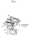
- FIG. 7 is an enlarged perspective view showing a configuration of a mounting portion for a shielding plate 40 according to the present embodiment.
- the configuration of components or parts other than the liquid tank 7 may be similar to those in the first embodiment.
- components or parts having functions or effects similar to in the first embodiment are denoted by the same reference symbols, and detailed descriptions thereof are omitted.
- the liquid tank 7 compared to that in the first embodiment, is characterized in the configuration of the shielding plate 40.
- the shielding plate 40 is formed by joining an L-shaped member 41 and side plates 44 and 45 into a box shape by means of welding, soldering or the like.
- the shielding plate 40 is attached to the underside face of the top lid 20 so as to surround the vent hole 25, thereby partitioning the interior of the liquid tank 7 in front and to the rear and left side of the vent hole 25 in the vehicle traveling direction, and below the vent hole 25 so as to form an isolated chamber 42 communicating with the vent hole 25.
- the shielding plate 40 In a portion of the shielding plate 40 continuing from the inner wall of the liquid tank 7 (that corresponds to the "first portion” and is formed by a side part 41 a of the L-shaped member 41 and the side plates 44 and 45), there is formed a rectangular shaped opening 43 at a position on the right side of the vent hole 25 in the vehicle widthwise direction, and the isolated chamber 42 and the inner space within the liquid tank 7 excluding this chamber 42 are communicated via the opening 43.
- the "second portion" of the shielding member is formed by a bottom part 41 b of the L-shaped member.
- FIG. 8 and FIG. 9 show a configuration of the L-shaped member 41 that constitutes the shielding plate 40 according to the present embodiment.
- FIG. 8 is a front view and FIG. 9 is a plan view.
- the L-shaped member 41 is formed by bending a flat thin plate in a substantial L-shape.
- the side part 41 a forms the "first portion" of the shielding member, and the bottom part 41 b forms the "second portion" thereof.
- the side plate 44 disposed on the front side also serves as a heat transfer plate that connects the heat exchange pipe 21 and the reducing agent supply pipe 8. That is to say, the side plate 44 is joined to the bottom part 41 b of the L-shaped member 41, and is also disposed so as to be in contact with both of the heat exchange pipe 21 and the reducing agent supply pipe 8.
- the engine coolant heated by the engine 1 travels through the heat exchange pipe 21, heat of the engine coolant is transferred to the reducing agent supply pipe 8 via the side plate 44, and the urea aqueous solution in the reducing agent supply pipe 8 is heated.
- the side part 41 a of the L-shaped member 41 is disposed on the left side of the vent hole 25 in relation to the vehicle traveling direction, attachment of the urea aqueous solution from this left side can be prevented.
- the side plate 44 prevents attachment of urea aqueous solution and this side plate 44 also serves a function of the heat transfer plate that connects the heat exchange pipe 21 and the reducing agent supply pipe 8, it is possible to promote thawing out of the urea aqueous solution that is frozen within the reducing agent supply pipe 8, while reducing the number and weight of required components.
- the shielding plate is formed such that the sectional shape thereof is of a U-shape or L-shape (overall box shape).
- the shape of the shielding plate is not limited to these shapes, and may be any shape that can surround the vent hole within the liquid tank.
- the shape of the shielding plate may be appropriately selected according to the direction of sloshing or waving of the liquid that occurs inside the liquid tank.
- a portion of the shielding plate also serves a function of the heat transfer plate.
- additional functions of the shielding plate are not limited to this. It is possible to constitute the shielding plate using other components provided in the liquid tank than the heat transfer plate.
- the shape of the liquid tank is not limited to the rectangular shape described above, and it is possible to adopt various shapes.
- the direction of waves that occur in the liquid tank due to vibrations of the engine during operation is pre-checked, and the shape of the shielding plate (in other words, the position of the opening) is set so that waves occurring in this direction are blocked.
- the present invention is not limited to a liquid tank for storing urea aqueous solution, and may also be applied to a liquid tank for storing other types of liquids, including other liquid reducing agents such as aqueous ammonia and fuel of hydrocarbon, lubricating oil, fuel and so forth.
Landscapes
- Engineering & Computer Science (AREA)
- Chemical & Material Sciences (AREA)
- Mechanical Engineering (AREA)
- Combustion & Propulsion (AREA)
- Transportation (AREA)
- Sustainable Energy (AREA)
- Life Sciences & Earth Sciences (AREA)
- Sustainable Development (AREA)
- Chemical Kinetics & Catalysis (AREA)
- Health & Medical Sciences (AREA)
- Toxicology (AREA)
- General Engineering & Computer Science (AREA)
- Exhaust Gas After Treatment (AREA)
- Exhaust Gas Treatment By Means Of Catalyst (AREA)
- Cooling, Air Intake And Gas Exhaust, And Fuel Tank Arrangements In Propulsion Units (AREA)
Abstract
Description
- The present invention relates to a liquid tank, a breather device therefor, and an exhaust gas purification device for an engine. In more detail, the invention relates to a technology for preventing liquid outflow through a vent hole provided for pressure relief, in a liquid tank installed on a vehicle.
- A vehicle provided with an internal combustion engine (hereunder, simply referred to as "engine") serving as a driving source, is equipped with a liquid tank for storing lubricating oil, fuel, and so forth to be used when operating the engine (Patent Document 1). Moreover, development of an exhaust gas purification device for an engine that uses the urea SCR (Selective Catalytic Reduction) has progressed in recent years, and is already being put to practical use. In this exhaust gas purification device that uses the urea SCR, there is installed a liquid tank for storing urea aqueous solution that serves as a liquid reducing agent (Patent Document 2). In the liquid tank, in addition to an opening for suctioning/discharging the stored liquid, there is provided a pressure relief vent hole that communicates between the interior of the liquid tank and the exterior thereof. This vent hole is generally constructed so as to open the interior of the liquid tank to the atmosphere. When the liquid is suctioned from the liquid tank, outside air flows in via the vent hole, thereby maintaining the pressure inside the liquid tank at a constant level.
- [Patent Document 1] Japanese Laid-open (Kokai) Patent Application Publication No.
H07(1995)-208138 - [Patent Document 2] Japanese Laid-open (Kokai) Patent Application Publication No.
2000-027627 - However, in a liquid tank having such a vent hole, there is a problem in that vibrations of the engine or vehicle body when traveling cause the stored liquid to flow out to the outside via the vent hole.
When the vehicle is traveling, vibrations of the engine or vehicle body are transmitted to the liquid tank, so that the wall face of the liquid tank is vibrated, then vibrations of the wall face are transmitted to and vibrate air inside the liquid tank, and cause the inside air to intermittently flow out from the liquid tank via the vent hole. Such a phenomena becomes significant if resonance occurs in the wall face of the liquid tank due to the frequency of the vibrations. In this case, sloshing or waving occurs in the liquid inside the liquid tank due to vibrations of the engine or acceleration/deceleration of the vehicle, and if the liquid is attached to the surroundings of the vent hole, this attached liquid together with the inside air flows out to the outside via the vent hole. - The present invention addresses the above problems, and provides a structure that makes attachment of liquid to the surroundings of the vent hole unlikely to occur, thereby preventing liquid outflow through the vent hole.
- The present invention provides a liquid tank, a breather device therefor, and an exhaust gas purification device for an engine.
The liquid tank according to the present invention includes: a tank main body configured to store a liquid therein, and provided with a vent hole that enables an interior of the tank main body to communicate with an exterior thereof; and a shielding member attached to the tank main body so as to surround the vent hole within the tank main body, and to form an isolated chamber communicated with the vent hole. The shielding member includes a first portion that is located to the side of the vent hole in the horizontal direction, and that forms an opening that communicates between the isolated chamber and an inner space of the tank main body excluding the isolated chamber, and in a second portion other than the first portion, the shielding member blocks movement of the liquid between the isolated chamber and the inner space. - The exhaust gas purification device for an engine according to the present invention includes: the above liquid tank configured to be appropriate for storing a liquid reducing agent as the above liquid; a NOx reducing catalytic converter installed in an exhaust gas passage of the engine; and a device arranged to be capable of supplying a liquid reducing agent stored in the liquid tank, to exhaust gas on an upstream of the reducing catalytic converter.
Moreover, the breather device according to the present invention is a device that relieves the pressure inside a liquid tank, and includes: a breather pipe forming a vent hole that enables an interior of the liquid tank to communicate with an exterior thereof; and a shielding member configured to be disposed with respect to the breather pipe, within the liquid tank so as to surround the vent hole, and to form an isolated chamber communicated with the vent hole. The shielding member includes, a first portion and a second portion. Here, the first portion is located to the side of the vent hole in the horizontal direction to enclose the vent hole, and forms an opening that communicates between the isolated chamber and an inner space within the liquid tank excluding the isolated chamber, and the second portion is located below the vent hole so as to block movement of liquid between the isolated chamber and the inner space. - According to the present invention, inside the liquid tank, the shielding member is disposed so as to surround the vent hole. In the first portion of the shielding member located to the side of the vent hole in the horizontal direction, while air circulation is allowed between the isolated chamber and the inner space of the liquid tank excluding the isolated chamber ("inner space of the liquid tank" and "space inside the liquid tank main body" excludes the isolated chamber unless otherwise stated), while in the second portion, movement of the liquid between the isolated chamber and the inner space is blocked. Consequently, even if sloshing or waving occurs in the liquid inside the liquid tank due to vibrations of the engine or the like when traveling, attachment of the liquid to the surroundings of the vent hole is suppressed by the first portion (excluding the opening) and the second portion, so that liquid outflow via the vent hole can be prevented. The pressure inside the liquid tank is relieved via; the vent hole, the isolated chamber formed by the shielding member, and the opening of the first portion.
- As such, those skilled in the art will appreciate that other objects and features of the present invention can be understood from the following description, with reference to the appended drawings.
The entire contents of Japanese Patent Application No.2006-085019 -
-
FIG. 1 is a schematic block diagram of an exhaust gas purification device for an engine, according to a first embodiment of the present invention. -
FIG. 2 is a front perspective view of a liquid tank according to the embodiment. -
FIG. 3 is a front sectional view of the liquid tank. -
FIG. 4 is a side sectional view of the liquid tank. -
FIG. 5 is a front sectional view of a liquid tank according to a second embodiment of the present invention. -
FIG. 6 is a side sectional view of the liquid tank. -
FIG. 7 is an enlarged perspective view of a mounting portion for a shielding plate. -
FIG. 8 is a front view of an L-shaped member that constitutes the shielding plate. -
FIG. 9 is a plan view of the L-shaped member. -
FIG. 10 is a bottom view of the mounting portion for the shielding plate constituted using the L-shaped member. - 1: Diesel engine, 2: Exhaust gas passage, 3: Reducing catalytic converter, 4: Urea aqueous solution injection nozzle, 5, 8: Reducing agent supply pipe, 6: Reducing agent supply device, 7: Liquid tank, 9: Reducing agent return pipe, 10: Control unit, 101: Accelerator sensor, 102: Crank angle sensor, 103: Coolant temperature sensor, 11: Refilling opening, 20: Top lid, 21: Heat exchange pipe, 22: Coolant supply opening, 23: Coolant discharge opening, 24: Breather pipe, 25: Vent hole, 26: Breather hose, 30, 40: Shielding plate, 31: U-shaped member that forms the shielding plate, 41: L-shaped member that forms the shielding plate, 31 a, 41 a: First portion of the shielding plate, 31b, 41b: Second portion of the shielding plate, 32, 42: Isolated chamber, 33, 43: Opening of the shielding plate, and 44, 45: Side plate.
- Hereunder is a description of embodiments of the present invention, with reference to the drawings.
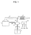
FIG. 1 is a schematic block diagram of an exhaust gas purification device for an engine, according to a first embodiment of the present invention.
In the present embodiment, an engine 1 is a diesel engine, and is employed to constitute a driving source of a vehicle (here, a large vehicle such as truck). - In an
exhaust gas passage 2 of the engine 1, there is interposed a reducingcatalytic converter 3 for nitrogen oxides (hereunder, referred to as "NOx"), and this reducingcatalytic converter 3 accelerates reductive purification of NOx in engine exhaust gas. In the present embodiment, urea aqueous solution serving as a liquid reducing agent is supplied to the exhaust gas for NOx purification, and a urea aqueous solution injection nozzle 4 (hereunder, simply referred to as "injection nozzle") is provided on the upstream of the reducingcatalytic converter 3. The injection nozzle 4 is inserted into theexhaust gas passage 2 in a manner of passing through the pipe wall of theexhaust gas passage 2 from the outside, and the tip end thereof is directed to the end face on the upstream side of the reducingcatalytic converter 3. - Urea aqueous solution to be supplied into the exhaust gas is stored in a
liquid tank 7. In consideration if simplifying use on a vehicle, urea, which is an ammonia precursor, has previously prepared in aqueous solution state. Theliquid tank 7 is connected, via a reducingagent supply pipe 8, to a reducingagent supply device 6. The reducingagent supply pipe 8 forms a delivery passage for the urea aqueous solution towards the reducingagent supply device 6. A member constituting thissupply pipe 8 corresponds to a "pipe member" according to the present embodiment. A feed pump (not shown in the drawing) feeds the urea aqueous solution in theliquid tank 7, via the reducingagent supply pipe 8, to the reducingagent supply device 6. The reducingagent supply device 6 is connected, via a reducingagent supply pipe 5, to the injection nozzle 4, and the urea aqueous solution that has been fed into the reducingagent supply device 6 is supplied together with compressed air, via the reducingagent supply pipe 5, to the injection nozzle 4. The urea supplied to the exhaust gas is hydrolyzed by exhaust heat, to generate ammonia and is then supplied to the reducingcatalytic converter 3 as a NOx reducing agent. The reducingagent supply device 6 is connected to theliquid tank 7 not only via the reducingagent supply pipe 8, but also via a reducingagent return pipe 9. A surplus portion of the urea aqueous solution supplied from theliquid tank 7 to the reducingagent supply device 6 that is not supplied to the injection nozzle 4 is returned to theliquid tank 7 via thisreturn pipe 9. - The operation of the reducing
agent supply device 6 is controlled by signals from an electronic control unit 10 (also serving as a control unit for the engine 1; hereunder simply referred to as "control unit"). Thecontrol unit 10 performs, based on the operating state of the engine 1, a predetermined calculation related to a reducing agent supply operation, and outputs a command signal to the reducingagent supply device 6. In the present embodiment, for detecting the operating state, there are provided: anaccelerator sensor 101 that detects an amount of operation of the accelerator pedal by a driver; acrank angle sensor 102 that detects a rotating angle of the crank shaft; and atemperature sensor 103 that detects the temperature of engine coolant. The engine rotating speed can be calculated based on signals from the crank angle sensor 12. -
FIG. 2 is a front perspective view showing an overall configuration of theliquid tank 7 according to the present embodiment.
Theliquid tank 7 is formed overall in a rectangular in cross-section with a depth D shorter than a width W (and height H), and is mounted on a vehicle in a state where the direction of the depth D coincides with the traveling direction of the vehicle. In an upper part of aleft side wall 7a of theliquid tank 7, there is provided arefilling opening 11 for refilling urea aqueous solution. -
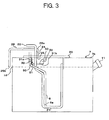
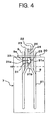
FIG. 3 andFIG. 4 show an internal structure of theliquid tank 7 according to the present embodiment.FIG. 3 is a sectional view of theliquid tank 7 viewed from the front, andFIG. 4 is a sectional view of theliquid tank 7 viewed from the right side.
In anupper wall 7b of theliquid tank 7, there is provided an opening for inserting the reducingagent supply pipe 8 and aheat exchange pipe 21 described later into theliquid tank 7, and atop lid 20 is fastened on theupper wall 7b so as to close up this opening. The reducingagent supply pipe 8, theheat exchange pipe 21, and the reducingagent return pipe 9 pass through and are fixed on thetop lid 20. In the state shown in the drawing with the top lid fastened, the reducingagent supply pipe 8 extends to the bottom part of the liquid tank 7 (inFIG. 3 the tip end is denoted byreference symbol 8a). The reducingagent return pipe 9 ends in close proximity to the underside face of thetop lid 20, and opens above the fluid level Hf at which the liquid tank is fully filled (inFIG. 4 the tip end is denoted byreference symbol 9a). - The
heat exchange pipe 21 is disposed inside theliquid tank 7. Theheat exchange pipe 21 is formed by bending a rod shaped pipe, and constitutes a heat exchanger that circulates engine coolant to thereby exchange heat between the engine coolant and the urea aqueous solution inside theliquid tank 7. Opposite ends of theheat exchange pipe 21 pass through thetop lid 20 so as to extend to the outside of theliquid tank 7. Oneopening 22 forms a supply port for engine coolant and anotheropening 23 forms a discharge port for the engine coolant. Theheat exchange pipe 21 constitutes a part of an engine coolant circulation passage. The engine coolant heated by the engine 1 travels through thisheat exchange pipe 21, thereby heating urea aqueous solution stored in theliquid tank 7. In a cold state of operation, even though the urea aqueous solution inside theliquid tank 7 is frozen at the time of starting the engine 1, heated engine coolant travels through theheat exchange pipe 21, thereby promoting thawing out of the frozen urea aqueous solution. Moreover, when the urea aqueous solution inside theliquid tank 7 is excessively heated, the engine coolant acts as a coolant for cooling down the urea aqueous solution, thereby preventing precipitation of urea. - Furthermore, on the
top lid 20 there is attached abreather pipe 24 hollowed therethrough in the axial direction. By means of thisbreather pipe 24, the interior of theliquid tank 7 is communicated with the exterior thereof, and avent hole 25 is formed for relieving the pressure inside theliquid tank 7. Thebreather pipe 24 extends upward beyond thetop lid 20, and to the top end of thebreather pipe 24, there is connected oneend 26a of abreather hose 26. Thebreather hose 26 extends sideways beyond the right side wall of theliquid tank 7, and anotherend 26b of thebreather hose 26 faces downward at a position in close proximity to the fluid level Hf at which theliquid tank 7 is fully filled. - Furthermore, on the
top lid 20, there is attached a shieldingplate 30 for suppressing attachment of the urea aqueous solution to the surroundings of thevent hole 25. In the present embodiment, the shieldingplate 30 is constituted by amember 31 made by bending a rectangular thin plate in a U-shape, and is fixed on the underside face of thetop lid 20 in a condition with abent part 31 b (that corresponds to a "second portion" of the shielding member) of theU-shaped member 31 directed downward below thevent hole 25. Thebent part 31 b is located above the fluid level Hf at which theliquid tank 7 is fully filled. Moreover, the shieldingplate 30 is disposed so as to straddle the opening (that is, the vent hole 25) of thebreather pipe 24 in the depth D direction of theliquid tank 7, that is, the vehicle traveling direction. In front and rear of thevent hole 25 in the traveling direction and below thevent hole 25, the shieldingpate 30 partitions the interior of theliquid tank 7 so as to form anisolated chamber 32 that communicates with thevent hole 25. In a portion of the shieldingplate 30 continuing from the inner wall of the liquid tank 7 (that corresponds to the "first portion" and is formed byflat face parts 31 a of the U-shaped member 31), there are provided oppositeU-shaped openings 33 at positions on the left and right sides of thevent hole 25 in the vehicle widthwise direction, and theisolated chamber 32 and the inner space of theliquid tank 7 excluding thischamber 32 are communicated via theseopenings 33. The shieldingplate 30 is formed with a wide width, and has a dimension in the width W direction that is greater than that in the depth D direction, in a state of being installed inside theliquid tank 7. In the present embodiment, the shieldingplate 30 is in direct contact with theheat exchange pipe 21. However, the shieldingplate 30 may be in contact with theheat exchange pipe 21 via a heat transfer body. The shieldingplate 30 and theheat exchange pipe 21 may be joined together by welding. In this case, the welding bead acts as a heat transfer body. - According to the present embodiment, the following effects can be achieved.
That is to say, in the present embodiment, inside theliquid tank 7, theU-shaped shielding plate 30 is installed so as to straddle thevent hole 25 in the vehicle traveling direction, and movement of the urea aqueous solution to the front and rear of thevent hole 25 in the traveling direction and below thevent hole 25 is thereby blocked. Therefore, even if sloshing or waving occurs in the urea aquwous solution in theliquid tank 7 due to vibrations of the engine 1 and acceleration/deceleration of the vehicle, the shieldingplate 30 suppresses attachment of the urea aqueous solution to the surroundings of thevent hole 25, so that outflow of the urea aqueous solution through thevent hole 25 can be prevented. In the present embodiment, in particular, theliquid tank 7 is formed in a rectangular in cross-section that is long in the width W direction with respect to the depth D direction, and the front and rear wall faces have an area that is greater than that of the left and right wall faces. Therefore, in the case where vibrations occur in the wall faces of theliquid tank 7 due to vibrations of the engine 1 during operation, in theliquid tank 7, waves are likely to occur between the front and rear wall surfaces, in other words, they are likely to occur in the depth D direction. In the present embodiment, as described above, the shieldingplate 30 is formed with a wide width, and has a larger dimension in the width W direction in a state of being installed inside theliquid tank 7. Therefore, waves that occur between the front and rear wall faces can be reliably stopped by the shieldingplate 30, so that attachment of the urea aqueous solution to the surroundings of thevent hole 25 can be suppressed. Moreover, by making the shieldingplate 30 have a greater dimension in the width W direction, then when the vehicle body sways left and right due to traveling course changes, a situation where the urea aqueous solution goes around thefirst portion 31a of the shieldingplate 30 and reaches thevent hole 25 via theopenings 33 can be suppressed. Moreover, by making the depth D direction of theliquid tank 7 coincide with the traveling direction of the vehicle, then even if waves occur in the urea aqueous solution due to acceleration/deceleration of the vehicle, attachment of the urea aqueous solution can be suppressed. - Furthermore, in the present embodiment, the shielding
plate 30 is in contact with theheat exchange pipe 21 and the engine coolant is circulated through thispipe 21, so that heat of the engine coolant is directly transferred to the shieldingplate 30. Therefore, in a cold state of operation, even though the urea aqueous solution is frozen, and lumps of ice are formed in theliquid tank 7 and block up theopenings 33 of the shieldingplate 30, this ice lumps can be quickly thawed out so that the function of thevent hole 25 can be maintained. On the other hand, when the urea aqueous solution is excessively heated, this is cooled by the engine coolant. Therefore, precipitation of urea from the urea aqueous solution can be prevented. - Hereunder, another embodiment of the present invention will be described.
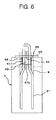
FIG. 5 andFIG. 6 show an internal structure of aliquid tank 7 according to a second embodiment of the present invention.FIG. 5 is a sectional view viewed from the front, andFIG. 6 is a sectional view viewed from the right side. Moreover,FIG. 7 is an enlarged perspective view showing a configuration of a mounting portion for a shieldingplate 40 according to the present embodiment. In the present embodiment, the configuration of components or parts other than theliquid tank 7 may be similar to those in the first embodiment. Moreover, inFIG. 5 andFIG. 6 , components or parts having functions or effects similar to in the first embodiment are denoted by the same reference symbols, and detailed descriptions thereof are omitted. - The
liquid tank 7 according to the present embodiment, compared to that in the first embodiment, is characterized in the configuration of the shieldingplate 40. As shown enlarged inFIG. 7 , in the present embodiment, the shieldingplate 40 is formed by joining an L-shapedmember 41 andside plates plate 40 is attached to the underside face of thetop lid 20 so as to surround thevent hole 25, thereby partitioning the interior of theliquid tank 7 in front and to the rear and left side of thevent hole 25 in the vehicle traveling direction, and below thevent hole 25 so as to form anisolated chamber 42 communicating with thevent hole 25. In a portion of the shieldingplate 40 continuing from the inner wall of the liquid tank 7 (that corresponds to the "first portion" and is formed by aside part 41 a of the L-shapedmember 41 and theside plates 44 and 45), there is formed a rectangular shapedopening 43 at a position on the right side of thevent hole 25 in the vehicle widthwise direction, and theisolated chamber 42 and the inner space within theliquid tank 7 excluding thischamber 42 are communicated via theopening 43. In the present embodiment, the "second portion" of the shielding member is formed by abottom part 41 b of the L-shaped member. -
FIG. 8 andFIG. 9 show a configuration of the L-shapedmember 41 that constitutes the shieldingplate 40 according to the present embodiment.FIG. 8 is a front view andFIG. 9 is a plan view.
The L-shapedmember 41 is formed by bending a flat thin plate in a substantial L-shape. Theside part 41 a forms the "first portion" of the shielding member, and thebottom part 41 b forms the "second portion" thereof. -
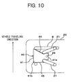
FIG. 10 is a bottom view of the mounting portion for the shieldingplate 40 according to the present embodiment. As shown inFIG. 10 , theside part 41 a of the L-shapedmember 41 is disposed to the side of thevent hole 25 in the horizontal direction (on the left side with respect to the vehicle traveling direction), and thebottom part 41 b is disposed below thevent hole 25, thereby partitioning the interior of theliquid tank 7 at their respective positions.
Theside plates side plate 44 in front of thevent hole 25 in the traveling direction, and anotherside plate 45 to the rear of thevent hole 25 in the traveling direction, respectively partition the interior of theliquid tank 7. In the present embodiment, theside plate 44 disposed on the front side also serves as a heat transfer plate that connects theheat exchange pipe 21 and the reducingagent supply pipe 8. That is to say, theside plate 44 is joined to thebottom part 41 b of the L-shapedmember 41, and is also disposed so as to be in contact with both of theheat exchange pipe 21 and the reducingagent supply pipe 8. When the engine coolant heated by the engine 1 travels through theheat exchange pipe 21, heat of the engine coolant is transferred to the reducingagent supply pipe 8 via theside plate 44, and the urea aqueous solution in the reducingagent supply pipe 8 is heated. - According to the present embodiment, since the
side part 41 a of the L-shapedmember 41 is disposed on the left side of thevent hole 25 in relation to the vehicle traveling direction, attachment of the urea aqueous solution from this left side can be prevented. In particular, according to the present embodiment, since theside plate 44 prevents attachment of urea aqueous solution and thisside plate 44 also serves a function of the heat transfer plate that connects theheat exchange pipe 21 and the reducingagent supply pipe 8, it is possible to promote thawing out of the urea aqueous solution that is frozen within the reducingagent supply pipe 8, while reducing the number and weight of required components. - In the above description, the shielding plate is formed such that the sectional shape thereof is of a U-shape or L-shape (overall box shape). However, the shape of the shielding plate is not limited to these shapes, and may be any shape that can surround the vent hole within the liquid tank. The shape of the shielding plate may be appropriately selected according to the direction of sloshing or waving of the liquid that occurs inside the liquid tank.
Moreover, in the second embodiment, a portion of the shielding plate also serves a function of the heat transfer plate. However, additional functions of the shielding plate are not limited to this. It is possible to constitute the shielding plate using other components provided in the liquid tank than the heat transfer plate. - Furthermore, the shape of the liquid tank is not limited to the rectangular shape described above, and it is possible to adopt various shapes. The direction of waves that occur in the liquid tank due to vibrations of the engine during operation is pre-checked, and the shape of the shielding plate (in other words, the position of the opening) is set so that waves occurring in this direction are blocked.
The present invention is not limited to a liquid tank for storing urea aqueous solution, and may also be applied to a liquid tank for storing other types of liquids, including other liquid reducing agents such as aqueous ammonia and fuel of hydrocarbon, lubricating oil, fuel and so forth. - The present invention has been described above by the preferred embodiments. However, the scope of the present invention is not limited by this description, and is to be judged in accordance with applicable provisions, based on the disclosure of the claims.
Claims (14)
- A liquid tank comprising:a tank main body configured to store a liquid therein, the tank main body including a vent hole enabling an interior of the tank main body to communicate with an exterior thereof; anda shielding member attached to the tank main body so as to surround the vent hole within the tank main body, and to form an isolated chamber communicated with the vent hole, whereinthe shielding member includes a first portion located to the side of the vent hole in the horizontal direction and a second portion other than the first portion, the first portion forming an opening that communicates between the isolated chamber and an inner space of the tank main body excluding the isolated chamber, and in the second portion, the shielding member blocks movement of the liquid between the isolated chamber and the inner space.
- A liquid tank comprising:a tank main body configured to store a liquid therein, the tank main body including a vent hole enabling an interior of the tank main body to communicate with an exterior thereof; anda shielding member attached to the tank main body so as to surround the vent hole within the tank main body, and form an isolated chamber communicated with the vent hole, whereinthe shielding member includes;a first portion disposed at the side of the vent hole in the horizontal direction to enclose the vent hole, the first portion forming an opening that communicates between the isolated chamber and an inner space of the tank main body excluding the isolated chamber, anda second portion located below the vent hole so as to block movement of the liquid between the isolated chamber and the inner space.
- The liquid tank according to claim 1, wherein the shielding member is constituted by a single member with a cross-section formed in a U-shape.
- The liquid tank according to claim 1, wherein the vent hole is provided in a lid part of the tank main body.
- The liquid tank according to claim 1, wherein
the tank main body is of a rectangular in cross-section with the depth less than the width, and
the shielding member is longer in the width direction of the tank main body than in the depth direction thereof. - The liquid tank according to claim 5 provided for a vehicle, wherein
the tank main body is fixed with respect to the vehicle, with the widthwise direction thereof aligned with the left to right direction of the vehicle. - A liquid tank according to claim 1 provided for a vehicle having an engine, further comprising a heat exchange pipe located inside the tank main body, and configured to circulate an coolant of the engine.
- The liquid tank according to claim 7, wherein the heat exchange pipe is located inside the tank main body, in contact with the shielding member.
- The liquid tank according to claim 8, wherein the heat exchange pipe is contacted with the shielding member via a heat transfer body.
- The liquid tank according to claim 7 further comprising a pipe member forming a delivery passage for the liquid, and
the heat exchange pipe is thermally contacted with the pipe member via the shielding member. - The liquid tank according to claim 10, wherein
the liquid is a urea aqueous solution, and
the pipe member is arranged to constitute a passage for delivering the urea aqueous solution stored in the tank main body, towards an exterior of the tank main body. - The liquid tank according to claim 1, wherein the liquid is a urea aqueous solution.
- An exhaust gas purification device for an engine, comprising:the liquid tank according to claim 1, configured to be appropriate for storing a liquid reducing agent as the liquid;a NOx reducing catalytic converter installed in an exhaust gas passage of the engine; anda device configured to be capable of supplying the liquid reducing agent stored in the liquid tank, to exhaust gas on the upstream of the reducing catalytic converter.
- A breather device for relieving the pressure inside a liquid tank, comprising:a breather pipe forming a vent hole that enables an interior of the liquid tank to communicate with an exterior thereof; anda shielding member configured to be disposed with respect to the breather pipe, within the liquid tank so as to surround the vent hole, and to form an isolated chamber communicated with the vent hole, whereinthe shielding member includes a first portion and a second portion, and whereinthe first portion locates to the side of the vent hole in the horizontal direction to enclose the vent hole, and forms an opening that communicates between the isolated chamber and an inner space within the liquid tank excluding the isolated chamber, andthe second portion locates below the vent hole so as to block movement of liquid between the isolated chamber and the inner space.
Applications Claiming Priority (2)
| Application Number | Priority Date | Filing Date | Title |
|---|---|---|---|
| JP2006085019A JP2007262900A (en) | 2006-03-27 | 2006-03-27 | Vehicular liquid tank and exhaust emission control device of engine having the tank |
| PCT/JP2007/052866 WO2007122846A1 (en) | 2006-03-27 | 2007-02-16 | Liquid tank, breather device for the liquid tank, and exhaust gas purification device for engine |
Publications (3)
| Publication Number | Publication Date |
|---|---|
| EP2006503A1 true EP2006503A1 (en) | 2008-12-24 |
| EP2006503A4 EP2006503A4 (en) | 2009-08-26 |
| EP2006503B1 EP2006503B1 (en) | 2011-07-13 |
Family
ID=38624763
Family Applications (1)
| Application Number | Title | Priority Date | Filing Date |
|---|---|---|---|
| EP07714396A Not-in-force EP2006503B1 (en) | 2006-03-27 | 2007-02-16 | Liquid tank, breather device for the liquid tank, and exhaust gas purification device for engine |
Country Status (5)
| Country | Link |
|---|---|
| US (1) | US20090038296A1 (en) |
| EP (1) | EP2006503B1 (en) |
| JP (1) | JP2007262900A (en) |
| CN (1) | CN101410600A (en) |
| WO (1) | WO2007122846A1 (en) |
Cited By (6)
| Publication number | Priority date | Publication date | Assignee | Title |
|---|---|---|---|---|
| WO2010099907A1 (en) * | 2009-03-06 | 2010-09-10 | Kautex Textron Gmbh & Co. Kg | Service fluid container |
| WO2012155291A1 (en) * | 2011-05-16 | 2012-11-22 | 苏州派格力减排系统有限公司 | Integrated scr metering injection system |
| WO2012155292A1 (en) * | 2011-05-16 | 2012-11-22 | 苏州派格力减排系统有限公司 | Integrated scr reducing agent storage device |
| EP2541007A4 (en) * | 2010-02-26 | 2014-02-19 | Isuzu Motors Ltd | Breather pipe structure for a liquid reductant storage tank |
| EP2541008A4 (en) * | 2010-02-26 | 2014-04-09 | Isuzu Motors Ltd | BREATHING TUBE STRUCTURE FOR LIQUID REDUCER STORAGE TANK |
| US10639579B2 (en) | 2014-10-01 | 2020-05-05 | Donaldson Company, Inc. | Pleated tank vent |
Families Citing this family (17)
| Publication number | Priority date | Publication date | Assignee | Title |
|---|---|---|---|---|
| US8056671B2 (en) * | 2007-10-12 | 2011-11-15 | Mazda Motor Corporation | Exhaust-gas purification device disposition structure of vehicle |
| DE202008002696U1 (en) * | 2008-02-26 | 2009-07-02 | Voss Automotive Gmbh | System for tempering an SCR additive in a motor vehicle |
| US8393142B2 (en) | 2010-04-30 | 2013-03-12 | Caterpillar Inc. | Reductant dosing manifold |
| BR112012031838B1 (en) | 2010-06-15 | 2020-12-08 | Shaw Development, Llc | head unit and combination |
| DE102010024022B4 (en) | 2010-06-16 | 2025-03-27 | Vitesco Technologies GmbH | Device for conveying liquid reducing agent |
| US8822887B2 (en) | 2010-10-27 | 2014-09-02 | Shaw Arrow Development, LLC | Multi-mode heater for a diesel emission fluid tank |
| JP5784425B2 (en) * | 2011-09-06 | 2015-09-24 | 日野自動車株式会社 | Breather hose for urea water tank |
| JP5978954B2 (en) * | 2012-11-26 | 2016-08-24 | 三菱自動車工業株式会社 | Rotating electrical machine equipment |
| FR3014137B1 (en) * | 2013-12-02 | 2017-07-21 | Inergy Automotive Systems Res (Societe Anonyme) | IMPROVED STORAGE SYSTEM FOR A LIQUID ADDITIVE |
| KR101518938B1 (en) * | 2013-12-17 | 2015-05-11 | 현대자동차 주식회사 | Urea solution venting system for vehicle |
| WO2014192318A1 (en) * | 2014-01-08 | 2014-12-04 | 株式会社小松製作所 | Reducing agent tank and work vehicle |
| USD729722S1 (en) | 2014-05-28 | 2015-05-19 | Shaw Development LLC | Diesel emissions fluid tank floor |
| USD729141S1 (en) | 2014-05-28 | 2015-05-12 | Shaw Development LLC | Diesel emissions fluid tank |
| JP6781705B2 (en) | 2015-01-28 | 2020-11-04 | ドナルドソン カンパニー,インコーポレイティド | Barrier vent assembly |
| DE102019214253A1 (en) * | 2019-09-19 | 2021-03-25 | Ford Global Technologies, Llc | Ice guiding device for containers |
| CN112347618B (en) * | 2020-10-21 | 2023-03-31 | 潍柴动力股份有限公司 | Method and device for determining urea thawing efficiency and storage medium |
| JP7658806B2 (en) * | 2021-06-02 | 2025-04-08 | 株式会社サンエー | Urea tank |
Family Cites Families (20)
| Publication number | Priority date | Publication date | Assignee | Title |
|---|---|---|---|---|
| JPS5116539A (en) * | 1974-08-01 | 1976-02-09 | Yamaha Motor Co Ltd | Jidonirinshano oirutankusochi |
| US4483454A (en) * | 1977-03-18 | 1984-11-20 | Lubbock Manufacturing Company | Baffle for liquid cargo carrier |
| JPS6119073Y2 (en) * | 1979-06-22 | 1986-06-09 | ||
| JPS563836A (en) | 1979-06-26 | 1981-01-16 | Enkuraa Bijinesu:Kk | Fragrance-emitting means |
| JPS61169725U (en) * | 1985-04-10 | 1986-10-21 | ||
| JPS6428319U (en) * | 1987-08-12 | 1989-02-20 | ||
| JPH01148920U (en) * | 1988-04-05 | 1989-10-16 | ||
| JPH028138A (en) | 1988-06-23 | 1990-01-11 | Nec Corp | Paper feed roller cleaning device |
| US4960153A (en) * | 1989-11-03 | 1990-10-02 | G. T. Products, Inc. | Fuel tank vapor vent valve |
| US4989572A (en) * | 1990-02-16 | 1991-02-05 | General Motors Corporation | Vehicle fuel system with reduced tank heating |
| JPH0424820A (en) | 1990-05-20 | 1992-01-28 | Fujitsu Ltd | Filing system device |
| JPH0727229Y2 (en) * | 1990-06-22 | 1995-06-21 | 八千代工業株式会社 | Fuel tank for vehicle |
| JP3161183B2 (en) * | 1993-09-27 | 2001-04-25 | スズキ株式会社 | Fuel inlet sealing structure for fuel tank |
| JP3765947B2 (en) * | 1998-07-13 | 2006-04-12 | 本田技研工業株式会社 | Vehicle fuel tank arrangement structure |
| JP2000027627A (en) | 1998-07-13 | 2000-01-25 | Hino Motors Ltd | Reducing agent warming device for exhaust gas purifying catalyst and exhaust gas purifying device incorporating the same |
| DE10155675A1 (en) * | 2001-08-18 | 2003-05-28 | Bosch Gmbh Robert | Method and device for storing and dosing a reducing agent |
| JP4243538B2 (en) * | 2001-08-18 | 2009-03-25 | ローベルト ボツシユ ゲゼルシヤフト ミツト ベシユレンクテル ハフツング | Method and apparatus for storing and metering reducing agent |
| EP2426329B1 (en) * | 2003-09-19 | 2013-05-01 | Nissan Diesel Motor Co., Ltd. | Exhaust gas purification device of engine |
| US7493894B2 (en) * | 2004-02-13 | 2009-02-24 | Kelch Corporation | Tank assembly and components |
| JP3686667B1 (en) * | 2004-04-27 | 2005-08-24 | 日産ディーゼル工業株式会社 | Reducing agent container structure |
-
2006
- 2006-03-27 JP JP2006085019A patent/JP2007262900A/en active Pending
-
2007
- 2007-02-16 WO PCT/JP2007/052866 patent/WO2007122846A1/en not_active Ceased
- 2007-02-16 EP EP07714396A patent/EP2006503B1/en not_active Not-in-force
- 2007-02-16 CN CNA200780011226XA patent/CN101410600A/en active Pending
-
2008
- 2008-09-26 US US12/285,004 patent/US20090038296A1/en not_active Abandoned
Cited By (9)
| Publication number | Priority date | Publication date | Assignee | Title |
|---|---|---|---|---|
| WO2010099907A1 (en) * | 2009-03-06 | 2010-09-10 | Kautex Textron Gmbh & Co. Kg | Service fluid container |
| US8360087B2 (en) | 2009-03-06 | 2013-01-29 | Kautex Textron Gmbh & Co. Kg | Operating fluid tank |
| EP2541007A4 (en) * | 2010-02-26 | 2014-02-19 | Isuzu Motors Ltd | Breather pipe structure for a liquid reductant storage tank |
| EP2541008A4 (en) * | 2010-02-26 | 2014-04-09 | Isuzu Motors Ltd | BREATHING TUBE STRUCTURE FOR LIQUID REDUCER STORAGE TANK |
| US9964015B2 (en) | 2010-02-26 | 2018-05-08 | Isuzu Motors Limited | Breather pipe structure for liquid reducing agent storage tank |
| WO2012155291A1 (en) * | 2011-05-16 | 2012-11-22 | 苏州派格力减排系统有限公司 | Integrated scr metering injection system |
| WO2012155292A1 (en) * | 2011-05-16 | 2012-11-22 | 苏州派格力减排系统有限公司 | Integrated scr reducing agent storage device |
| US9279352B2 (en) | 2011-05-16 | 2016-03-08 | Suzhou Powergreen Emission Solution System Co., Ltd | Integrated SCR metering injection system |
| US10639579B2 (en) | 2014-10-01 | 2020-05-05 | Donaldson Company, Inc. | Pleated tank vent |
Also Published As
| Publication number | Publication date |
|---|---|
| WO2007122846A1 (en) | 2007-11-01 |
| CN101410600A (en) | 2009-04-15 |
| EP2006503A4 (en) | 2009-08-26 |
| JP2007262900A (en) | 2007-10-11 |
| US20090038296A1 (en) | 2009-02-12 |
| EP2006503B1 (en) | 2011-07-13 |
Similar Documents
| Publication | Publication Date | Title |
|---|---|---|
| EP2006503B1 (en) | Liquid tank, breather device for the liquid tank, and exhaust gas purification device for engine | |
| US8184964B2 (en) | Tank for storing a reducing agent | |
| EP1662103B1 (en) | Exhaust gas purification device of engine | |
| US20090127265A1 (en) | Liquid receptacle for a vehicle | |
| JP4550481B2 (en) | Automotive liquid tank | |
| EP1731882B1 (en) | Structure for reducing agent container | |
| US8586895B2 (en) | Vehicle tank for a liquid reducing agent, in particular for a urea solution | |
| US9038374B2 (en) | Delivery device and tank configuration for a reducing agent and motor vehicle having a tank configuration | |
| CN102713181B (en) | Tank device and metering system for reducing agent | |
| EP1757781B1 (en) | Structure of container for reducing agent | |
| EP2006502B1 (en) | Breather device, liquid tank, and exhaust gas purifying device for engine | |
| JP3686668B1 (en) | Reducing agent container structure | |
| US9556772B2 (en) | Fuel tank and liquid tank configuration for a work vehicle | |
| CN101828012A (en) | Tank for storing a reducing agent | |
| US10507722B2 (en) | Container assembly for a motor vehicle | |
| EP2646665B1 (en) | Reducing agent storage system with warming device and method for warming of reducing agent | |
| JP2020029845A (en) | Reductant tank and exhaust emission control device | |
| EP3615777B1 (en) | Reductant injection system | |
| JP7310308B2 (en) | Vehicle urea water tank | |
| US8491859B2 (en) | Device having an injector for a liquid reducing agent, configuration having the device and methods of using the device and the configuration | |
| WO2024095500A1 (en) | Tank |
Legal Events
| Date | Code | Title | Description |
|---|---|---|---|
| PUAI | Public reference made under article 153(3) epc to a published international application that has entered the european phase |
Free format text: ORIGINAL CODE: 0009012 |
|
| 17P | Request for examination filed |
Effective date: 20081027 |
|
| AK | Designated contracting states |
Kind code of ref document: A1 Designated state(s): DE FR NL SE |
|
| DAX | Request for extension of the european patent (deleted) | ||
| RBV | Designated contracting states (corrected) |
Designated state(s): DE FR NL SE |
|
| A4 | Supplementary search report drawn up and despatched |
Effective date: 20090727 |
|
| 17Q | First examination report despatched |
Effective date: 20091102 |
|
| GRAP | Despatch of communication of intention to grant a patent |
Free format text: ORIGINAL CODE: EPIDOSNIGR1 |
|
| GRAS | Grant fee paid |
Free format text: ORIGINAL CODE: EPIDOSNIGR3 |
|
| GRAA | (expected) grant |
Free format text: ORIGINAL CODE: 0009210 |
|
| AK | Designated contracting states |
Kind code of ref document: B1 Designated state(s): DE FR NL SE |
|
| REG | Reference to a national code |
Ref country code: DE Ref legal event code: R096 Ref document number: 602007015764 Country of ref document: DE Effective date: 20110901 |
|
| REG | Reference to a national code |
Ref country code: NL Ref legal event code: T3 |
|
| REG | Reference to a national code |
Ref country code: SE Ref legal event code: TRGR |
|
| PLBE | No opposition filed within time limit |
Free format text: ORIGINAL CODE: 0009261 |
|
| STAA | Information on the status of an ep patent application or granted ep patent |
Free format text: STATUS: NO OPPOSITION FILED WITHIN TIME LIMIT |
|
| 26N | No opposition filed |
Effective date: 20120416 |
|
| REG | Reference to a national code |
Ref country code: DE Ref legal event code: R097 Ref document number: 602007015764 Country of ref document: DE Effective date: 20120416 |
|
| REG | Reference to a national code |
Ref country code: NL Ref legal event code: V1 Effective date: 20120901 |
|
| PG25 | Lapsed in a contracting state [announced via postgrant information from national office to epo] |
Ref country code: SE Free format text: LAPSE BECAUSE OF NON-PAYMENT OF DUE FEES Effective date: 20120217 |
|
| REG | Reference to a national code |
Ref country code: FR Ref legal event code: ST Effective date: 20121031 |
|
| REG | Reference to a national code |
Ref country code: DE Ref legal event code: R119 Ref document number: 602007015764 Country of ref document: DE Effective date: 20120901 |
|
| PG25 | Lapsed in a contracting state [announced via postgrant information from national office to epo] |
Ref country code: NL Free format text: LAPSE BECAUSE OF NON-PAYMENT OF DUE FEES Effective date: 20120901 Ref country code: FR Free format text: LAPSE BECAUSE OF NON-PAYMENT OF DUE FEES Effective date: 20120229 |
|
| PG25 | Lapsed in a contracting state [announced via postgrant information from national office to epo] |
Ref country code: DE Free format text: LAPSE BECAUSE OF NON-PAYMENT OF DUE FEES Effective date: 20120901 |