EP2006493A2 - Wärmeverwaltungssystem für Flugzeugkombinationsmotoren - Google Patents
Wärmeverwaltungssystem für Flugzeugkombinationsmotoren Download PDFInfo
- Publication number
- EP2006493A2 EP2006493A2 EP08252057A EP08252057A EP2006493A2 EP 2006493 A2 EP2006493 A2 EP 2006493A2 EP 08252057 A EP08252057 A EP 08252057A EP 08252057 A EP08252057 A EP 08252057A EP 2006493 A2 EP2006493 A2 EP 2006493A2
- Authority
- EP
- European Patent Office
- Prior art keywords
- coolant
- engine
- heat exchanger
- combustion engine
- intermittent combustion
- Prior art date
- Legal status (The legal status is an assumption and is not a legal conclusion. Google has not performed a legal analysis and makes no representation as to the accuracy of the status listed.)
- Withdrawn
Links
- 239000002826 coolant Substances 0.000 claims abstract description 170
- 238000002485 combustion reaction Methods 0.000 claims abstract description 112
- 238000001816 cooling Methods 0.000 claims abstract description 56
- 230000008878 coupling Effects 0.000 claims abstract description 39
- 238000010168 coupling process Methods 0.000 claims abstract description 39
- 238000005859 coupling reaction Methods 0.000 claims abstract description 39
- 239000012530 fluid Substances 0.000 claims abstract description 33
- 239000010705 motor oil Substances 0.000 claims abstract description 14
- 230000001050 lubricating effect Effects 0.000 claims abstract description 7
- 239000000446 fuel Substances 0.000 claims description 70
- 239000000314 lubricant Substances 0.000 claims description 66
- 230000009977 dual effect Effects 0.000 claims description 8
- 239000004020 conductor Substances 0.000 claims description 7
- 230000004044 response Effects 0.000 claims description 3
- 239000007789 gas Substances 0.000 description 23
- 239000007788 liquid Substances 0.000 description 17
- 239000002516 radical scavenger Substances 0.000 description 7
- 238000005461 lubrication Methods 0.000 description 6
- 239000007858 starting material Substances 0.000 description 6
- 230000032258 transport Effects 0.000 description 4
- 238000010521 absorption reaction Methods 0.000 description 3
- 230000006835 compression Effects 0.000 description 3
- 238000007906 compression Methods 0.000 description 3
- LYCAIKOWRPUZTN-UHFFFAOYSA-N Ethylene glycol Chemical compound OCCO LYCAIKOWRPUZTN-UHFFFAOYSA-N 0.000 description 2
- QVGXLLKOCUKJST-UHFFFAOYSA-N atomic oxygen Chemical compound [O] QVGXLLKOCUKJST-UHFFFAOYSA-N 0.000 description 2
- 238000010586 diagram Methods 0.000 description 2
- 230000005611 electricity Effects 0.000 description 2
- 230000005670 electromagnetic radiation Effects 0.000 description 2
- 230000010006 flight Effects 0.000 description 2
- 239000001301 oxygen Substances 0.000 description 2
- 229910052760 oxygen Inorganic materials 0.000 description 2
- OKTJSMMVPCPJKN-UHFFFAOYSA-N Carbon Chemical compound [C] OKTJSMMVPCPJKN-UHFFFAOYSA-N 0.000 description 1
- UFHFLCQGNIYNRP-UHFFFAOYSA-N Hydrogen Chemical compound [H][H] UFHFLCQGNIYNRP-UHFFFAOYSA-N 0.000 description 1
- 230000008901 benefit Effects 0.000 description 1
- 229910052799 carbon Inorganic materials 0.000 description 1
- 238000006243 chemical reaction Methods 0.000 description 1
- 239000000567 combustion gas Substances 0.000 description 1
- 238000004590 computer program Methods 0.000 description 1
- 230000000694 effects Effects 0.000 description 1
- 230000007717 exclusion Effects 0.000 description 1
- 239000002828 fuel tank Substances 0.000 description 1
- 239000003502 gasoline Substances 0.000 description 1
- 239000001257 hydrogen Substances 0.000 description 1
- 229910052739 hydrogen Inorganic materials 0.000 description 1
- WGCNASOHLSPBMP-UHFFFAOYSA-N hydroxyacetaldehyde Natural products OCC=O WGCNASOHLSPBMP-UHFFFAOYSA-N 0.000 description 1
- 238000002347 injection Methods 0.000 description 1
- 239000007924 injection Substances 0.000 description 1
- 238000000034 method Methods 0.000 description 1
- 239000000203 mixture Substances 0.000 description 1
- 230000008569 process Effects 0.000 description 1
- 230000001141 propulsive effect Effects 0.000 description 1
- 230000000153 supplemental effect Effects 0.000 description 1
- XLYOFNOQVPJJNP-UHFFFAOYSA-N water Substances O XLYOFNOQVPJJNP-UHFFFAOYSA-N 0.000 description 1
Images

Classifications
-
- F—MECHANICAL ENGINEERING; LIGHTING; HEATING; WEAPONS; BLASTING
- F01—MACHINES OR ENGINES IN GENERAL; ENGINE PLANTS IN GENERAL; STEAM ENGINES
- F01D—NON-POSITIVE DISPLACEMENT MACHINES OR ENGINES, e.g. STEAM TURBINES
- F01D15/00—Adaptations of machines or engines for special use; Combinations of engines with devices driven thereby
- F01D15/10—Adaptations for driving, or combinations with, electric generators
-
- F—MECHANICAL ENGINEERING; LIGHTING; HEATING; WEAPONS; BLASTING
- F01—MACHINES OR ENGINES IN GENERAL; ENGINE PLANTS IN GENERAL; STEAM ENGINES
- F01D—NON-POSITIVE DISPLACEMENT MACHINES OR ENGINES, e.g. STEAM TURBINES
- F01D13/00—Combinations of two or more machines or engines
- F01D13/02—Working-fluid interconnection of machines or engines
-
- F—MECHANICAL ENGINEERING; LIGHTING; HEATING; WEAPONS; BLASTING
- F01—MACHINES OR ENGINES IN GENERAL; ENGINE PLANTS IN GENERAL; STEAM ENGINES
- F01D—NON-POSITIVE DISPLACEMENT MACHINES OR ENGINES, e.g. STEAM TURBINES
- F01D25/00—Component parts, details, or accessories, not provided for in, or of interest apart from, other groups
- F01D25/08—Cooling; Heating; Heat-insulation
- F01D25/12—Cooling
- F01D25/125—Cooling of bearings
-
- F—MECHANICAL ENGINEERING; LIGHTING; HEATING; WEAPONS; BLASTING
- F02—COMBUSTION ENGINES; HOT-GAS OR COMBUSTION-PRODUCT ENGINE PLANTS
- F02C—GAS-TURBINE PLANTS; AIR INTAKES FOR JET-PROPULSION PLANTS; CONTROLLING FUEL SUPPLY IN AIR-BREATHING JET-PROPULSION PLANTS
- F02C6/00—Plural gas-turbine plants; Combinations of gas-turbine plants with other apparatus; Adaptations of gas-turbine plants for special use
- F02C6/04—Gas-turbine plants providing heated or pressurised working fluid for other apparatus, e.g. without mechanical power output
- F02C6/06—Gas-turbine plants providing heated or pressurised working fluid for other apparatus, e.g. without mechanical power output providing compressed gas
- F02C6/08—Gas-turbine plants providing heated or pressurised working fluid for other apparatus, e.g. without mechanical power output providing compressed gas the gas being bled from the gas-turbine compressor
-
- F—MECHANICAL ENGINEERING; LIGHTING; HEATING; WEAPONS; BLASTING
- F02—COMBUSTION ENGINES; HOT-GAS OR COMBUSTION-PRODUCT ENGINE PLANTS
- F02C—GAS-TURBINE PLANTS; AIR INTAKES FOR JET-PROPULSION PLANTS; CONTROLLING FUEL SUPPLY IN AIR-BREATHING JET-PROPULSION PLANTS
- F02C6/00—Plural gas-turbine plants; Combinations of gas-turbine plants with other apparatus; Adaptations of gas-turbine plants for special use
- F02C6/04—Gas-turbine plants providing heated or pressurised working fluid for other apparatus, e.g. without mechanical power output
- F02C6/10—Gas-turbine plants providing heated or pressurised working fluid for other apparatus, e.g. without mechanical power output supplying working fluid to a user, e.g. a chemical process, which returns working fluid to a turbine of the plant
-
- F—MECHANICAL ENGINEERING; LIGHTING; HEATING; WEAPONS; BLASTING
- F02—COMBUSTION ENGINES; HOT-GAS OR COMBUSTION-PRODUCT ENGINE PLANTS
- F02C—GAS-TURBINE PLANTS; AIR INTAKES FOR JET-PROPULSION PLANTS; CONTROLLING FUEL SUPPLY IN AIR-BREATHING JET-PROPULSION PLANTS
- F02C7/00—Features, components parts, details or accessories, not provided for in, or of interest apart form groups F02C1/00 - F02C6/00; Air intakes for jet-propulsion plants
- F02C7/12—Cooling of plants
- F02C7/16—Cooling of plants characterised by cooling medium
- F02C7/18—Cooling of plants characterised by cooling medium the medium being gaseous, e.g. air
- F02C7/185—Cooling means for reducing the temperature of the cooling air or gas
-
- F—MECHANICAL ENGINEERING; LIGHTING; HEATING; WEAPONS; BLASTING
- F02—COMBUSTION ENGINES; HOT-GAS OR COMBUSTION-PRODUCT ENGINE PLANTS
- F02C—GAS-TURBINE PLANTS; AIR INTAKES FOR JET-PROPULSION PLANTS; CONTROLLING FUEL SUPPLY IN AIR-BREATHING JET-PROPULSION PLANTS
- F02C7/00—Features, components parts, details or accessories, not provided for in, or of interest apart form groups F02C1/00 - F02C6/00; Air intakes for jet-propulsion plants
- F02C7/22—Fuel supply systems
- F02C7/224—Heating fuel before feeding to the burner
-
- F—MECHANICAL ENGINEERING; LIGHTING; HEATING; WEAPONS; BLASTING
- F02—COMBUSTION ENGINES; HOT-GAS OR COMBUSTION-PRODUCT ENGINE PLANTS
- F02K—JET-PROPULSION PLANTS
- F02K3/00—Plants including a gas turbine driving a compressor or a ducted fan
- F02K3/02—Plants including a gas turbine driving a compressor or a ducted fan in which part of the working fluid by-passes the turbine and combustion chamber
- F02K3/04—Plants including a gas turbine driving a compressor or a ducted fan in which part of the working fluid by-passes the turbine and combustion chamber the plant including ducted fans, i.e. fans with high volume, low pressure outputs, for augmenting the jet thrust, e.g. of double-flow type
- F02K3/06—Plants including a gas turbine driving a compressor or a ducted fan in which part of the working fluid by-passes the turbine and combustion chamber the plant including ducted fans, i.e. fans with high volume, low pressure outputs, for augmenting the jet thrust, e.g. of double-flow type with front fan
-
- F—MECHANICAL ENGINEERING; LIGHTING; HEATING; WEAPONS; BLASTING
- F02—COMBUSTION ENGINES; HOT-GAS OR COMBUSTION-PRODUCT ENGINE PLANTS
- F02K—JET-PROPULSION PLANTS
- F02K3/00—Plants including a gas turbine driving a compressor or a ducted fan
- F02K3/08—Plants including a gas turbine driving a compressor or a ducted fan with supplementary heating of the working fluid; Control thereof
- F02K3/105—Heating the by-pass flow
- F02K3/115—Heating the by-pass flow by means of indirect heat exchange
-
- F—MECHANICAL ENGINEERING; LIGHTING; HEATING; WEAPONS; BLASTING
- F05—INDEXING SCHEMES RELATING TO ENGINES OR PUMPS IN VARIOUS SUBCLASSES OF CLASSES F01-F04
- F05D—INDEXING SCHEME FOR ASPECTS RELATING TO NON-POSITIVE-DISPLACEMENT MACHINES OR ENGINES, GAS-TURBINES OR JET-PROPULSION PLANTS
- F05D2220/00—Application
- F05D2220/70—Application in combination with
- F05D2220/76—Application in combination with an electrical generator
-
- F—MECHANICAL ENGINEERING; LIGHTING; HEATING; WEAPONS; BLASTING
- F05—INDEXING SCHEMES RELATING TO ENGINES OR PUMPS IN VARIOUS SUBCLASSES OF CLASSES F01-F04
- F05D—INDEXING SCHEME FOR ASPECTS RELATING TO NON-POSITIVE-DISPLACEMENT MACHINES OR ENGINES, GAS-TURBINES OR JET-PROPULSION PLANTS
- F05D2260/00—Function
- F05D2260/20—Heat transfer, e.g. cooling
- F05D2260/213—Heat transfer, e.g. cooling by the provision of a heat exchanger within the cooling circuit
-
- Y—GENERAL TAGGING OF NEW TECHNOLOGICAL DEVELOPMENTS; GENERAL TAGGING OF CROSS-SECTIONAL TECHNOLOGIES SPANNING OVER SEVERAL SECTIONS OF THE IPC; TECHNICAL SUBJECTS COVERED BY FORMER USPC CROSS-REFERENCE ART COLLECTIONS [XRACs] AND DIGESTS
- Y02—TECHNOLOGIES OR APPLICATIONS FOR MITIGATION OR ADAPTATION AGAINST CLIMATE CHANGE
- Y02T—CLIMATE CHANGE MITIGATION TECHNOLOGIES RELATED TO TRANSPORTATION
- Y02T50/00—Aeronautics or air transport
- Y02T50/60—Efficient propulsion technologies, e.g. for aircraft
Definitions
- the present invention relates to gas turbine engines for aircraft and, more particularly, to a gas turbine engine coupled to a corresponding auxiliary intermittent combustion engine.
- Gas turbine engines as continuous combustion, open Brayton cycle internal combustion engines have come to dominate as the power plants for larger, faster aircraft to essentially the exclusion of reciprocating engines, or internal, intermittent combustion engines, earlier used as power plants for these kinds of aircraft. This is largely because of the greater power-to-weight ratio of gas turbine engines versus intermittent combustion engines, especially in large horsepower engines, or, more appropriately, large thrust engines in which those large thrusts are provided with a relatively small, and so smaller drag, frontal area engine structures relative to reciprocating engines.
- Gas turbine engines generate such large thrusts for propulsion, or horsepower for engines with an output shaft, by combining large volumes of air with large amounts of fuel, and thereby form a jet of large velocity leading to the capability to provide desired speedy flights.
- gas turbine engine as the sole source of power to operate an electrical power generator is to add in the aircraft a further intermittent combustion internal combustion engine, such as gasoline engines operating on the any of the Diesel, Miller, Otto or Wankel cycles.
- Such engines can operate with a fuel efficiency on the order of seventy percent (70%) better than that of a continuous combustion (Brayton cycle) internal combustion gas turbine engine.
- internal combustion engines of all kinds face the possibility of limited power output because of the relatively small air pressures there limiting the chemical reactions of oxygen with hydrogen and oxygen with carbon in the burning of the engine fuel in the engine combustion chamber or chambers.
- Such compressors can provide considerably more compressed air than the minimum needed for this purpose thereby allowing some of this compressed air to be delivered through an air transport duct to the air intake of an intermittent combustion internal combustion engine so that, in effect, the compressors of the gas turbine engine serve as a very capable supercharger for that intermittent combustion engine.
- this intermittent combustion engine can be operated at the same relatively high altitudes at which the gas turbine engine propelling the aircraft operates while this turbine engine is also supplying compressed air to that intermittent combustion engine.
- the intermittent combustion engine can be used as a power source for an electrical power generator that can generate much greater amounts of electrical power than can one powered by a gas turbine engine.
- the amount of electrical power needed at any time during flights thereof substantially determines the amount of torque needed to be supplied by the intermittent combustion engine to the electrical power generator.
- the amount of torque generated is determined by the amount of fuel supplied to the combustion chambers of the intermittent combustion engine, and there is a corresponding amount of air that must also be supplied to those chambers to support the desired combustion therein made possible at those high altitudes by the turbocharging of the gas turbine engine.
- the present invention provides an engine combination for generating forces with a gas turbine engine having an air inlet open to the atmosphere, an air compressor, a combustor, a turbine and an exhaust exit nozzle open to the atmosphere positioned along a fluids flow path passing through all for generating force, and utilizing an engine lubricant for lubricating moving components in the gas turbine engine, with the air compressor having an air transfer duct extending therefrom so as to receive compressed air therein.
- an internal combustion engine is provided in the combination as an intermittent combustion engine having an air intake coupled to combustion chambers therein along with a rotatable output shaft for generating force also coupled to those combustion chambers, and utilizing a coolant for transporting heat generated in the intermittent combustion engine away therefrom, the air transfer duct being connected to the air intake to transfer compressed air thereto.
- a coupling heat exchanger is coupled to both the gas turbine engine and the intermittent combustion engine as a first coupling subsystem to have the engine lubricant and the coolant pass therethrough to thereby permit the coolant to transport heat in the engine lubricant away therefrom.
- a further cooling heat exchanger is coupled to both the coupling heat exchanger and the intermittent combustion engine as a second coupling subsystem to have a remote fluid from a source thereof and the coolant pass therethrough to permit the remote fluid to transport heat in the coolant away therefrom, and with the coolant also circulating through at least one of the coupling heat exchanger and the intermittent combustion engine.
- a primary electrical generator having an output conductor can have a rotatable input shaft connected to the intermittent combustion engine output shaft with the output conductor being electrically energized in response to rotation of the input shaft, and utilizing a generator lubricant that is cooled by the coolant in another coupling heat exchanger.
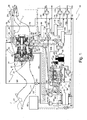
- Figure 1 shows a schematic representation of a cross section side view of a portion of an aircraft with an example of such a cooling system for a gas turbine engine and intermittent combustion engine combination, 10, in an arrangement in which most of the aircraft structure in which they are positioned has been omitted from this view.
- an engine duct 11, in that aircraft that is shown and has an air inlet, 12, facing forward in the aircraft.
- the configuration shown for duct 11, with its somewhat sinuous shape, is from, a stealth type military aircraft, several kinds of which are unmanned aircraft.
- This duct first curves downward, coming from the front of the aircraft at the duct opening provided by air inlet 12 to the atmosphere from which an airstream, 13, is drawn.
- the duct then curves upward to open to a gas turbine engine provided as a turbofan engine, 14, in engine duct 11 which uses airstream 13 for combustion and for fan forced air propulsion purposes.
- This passageway curvature of duct 11 past air inlet 12 serves to hide the front of engine 14 from impinging electromagnetic radiation at various wavelengths.
- Outer portions, 15, of duct 11 adjacent engine 14 past a splitter convey the fan forced air provided by engine 14 for propulsion purposes into the remainder of duct 11 past engine 14 toward the outlet of duct 11 to the atmosphere as will be described below.
- This fan forced air and the combustion products resulting from combustion in engine 14 are forced out of the remainder of engine duct 11 to an exit nozzle, 16, serving as the outlet of duct 11.
- a fluid actuation system, 17, provides the force to partially open and close nozzle 16 during the operation of turbofan engine 14.
- duct 11 past engine 14 first curves downward, coming from that engine, and then the duct curves upward to open to nozzle 16.
- this passageway curvature of duct 11 past engine 14 serves to hide the rear of engine 14 from electromagnetic radiation at various wavelengths impinging at the rear of the aircraft.
- Engine 14 has an air inlet guide vane, 20, followed by a high pressure fan, 21, as the fan for the turbofan engine to force air outside and past a splitter, 22, and then through duct portions 15 into the rear of duct 11 and out of that duct through nozzle 16 to exit to the atmosphere.
- high pressure fan 21 also serves as a low pressure air compressor through delivering compressed air inside splitter 22 to a high pressure air compressor, 23.
- the compressed air from high pressure compressor 23 arrives at a combustor, 24, to which fuel is also delivered and burned.
- the combustion products form a jet of fluid which impinges first on a high pressure turbine, 25, and then on a low pressure turbine, 26, to cause them to rotate which, through appropriate mechanical linkings, leads to high pressure compressor 23 and high pressure fan 21 being forced thereby to also rotate.
- the combustion products then reach the remainder of duct 11 past engine 14 to exit through nozzle 16 to the atmosphere.
- the thrust provided by the air from fan 21 forced out of nozzle 16 and the combustion products exiting through that nozzle is supplemented by the thrust provided by air from fan 21 that is forced out of a cooling duct, 27, extending toward the rear of engine 14 from a part of outer duct portion 15 that opens thereto just to the rear of splitter 22.
- the air entering this cooling duct from outer portion 15 is heated in an air-to-coolant heat exchanger, 28, to provide this added thrust while removing heat from the engines and generator coolant, and this air is forced to exit through a further controlled variable area nozzle, 29, having a position set by a control motor, 29'.
- the coolant enters a tube at the left entrance port of air-to-coolant heat exchanger 28, flows through a spaced apart set of tubes parallely connected to that port, and exits those tubes through the right exit port of this exchanger to which the tubes are also parallely connected at their opposite ends. Air flows through cooling duct 27 from outer portion 15 about and past this set of tubes to absorb heat therefrom which it transports to nozzle 29.
- a compressed air conveyance duct, 30, is connected at one end into turbofan engine 14 to receive compressed air from high pressure compressor 23 through a compressed air flow control valve, 31, typically controlled by a system computer or controller (not shown but typically an engine control computer or an aircraft systems computer either eliminating the need for such an engine control computer or operating with it in a distributed control system), and used to control the flow of compressed air from high pressure compressor 23 through duct 30.
- the opposite end of duct 30 is connected to an air intake, or intake manifold, 32, leading to engine air intake valves, 33, for an intermittent combustion engine, 34, represented in the example of Figure 2 as a Diesel or Otto cycle engine.
- Intermittent combustion engine 34 is shown positioned forward in the aircraft of turbofan engine 14 to shift the center of mass of the aircraft forward to counter some of the weight of engine 14 but other positions are possible to be used if desired.
- Valves 33 in engine 34 control the air taken into combustion chambers, 35, bounded by an engine block, 36, providing the basic structure of engine 34 and by pistons, 37.
- Each chamber also has an exhaust valve, 38, through which combustion products are exhausted to an exhaust manifold, 39.
- a rotatable crankshaft, 40 has a connecting rod, 41, rotatably coupling it to a corresponding one of each of pistons 37.
- a rotatable camshaft, 42 is used to open and close air intake valves 33 and exhaust valves 38 in a suitable sequence.
- Crankshaft 40 under the control of a system controller not shown, is rotated by the force on pistons 37 transmitted thereto by corresponding ones of connecting rods 41 due to repeated combustion events in the corresponding combustion chamber 35 which events occur in all of chambers 35 in a suitable sequence before repeating. These events correspondingly use the air quantities taken through valves 33 repeatedly into, and the fuel quantities repeatedly injected into, those chambers for combustion.
- the fuel quantities are injected by a fuel injection system not seeable in this figure and the magnitudes thereof are used to select the mechanical power output of crankshaft 40 of the intermittent combustion engine.
- the resulting combustion products are correspondingly repeatedly rejected from those chambers through valves 38.
- intermittent combustion engine 34 If an Otto cycle engine is used as intermittent combustion engine 34, the combustion events are initiated by the repeated sparkings of spark plugs not shown in this figure in a suitable sequence across combustion chambers 35 under the control of the system controller.
- intermittent combustion engine 34 has a cooling system not shown for cooling the engine structure about combustion chambers 35.
- crankshaft 40 is suitably fastened to an input shaft, 43, of a primary electrical power generator, 44.
- the resulting rotation of input shaft 43 electrically energizes output electrical conductors, 45, of generator 44 to thereby generate the desired electrical power thereat for operating aircraft devices (not or not all shown).
- the demand for electrical power in the aircraft is used as a basis to select the fuel quantities injected in the combustion chambers of the intermittent combustion engine to have that engine supply sufficient mechanical power to crankshaft 40 to sufficiently rotate input shaft 43 of generator 44 to meet that demand.
- An exhaust duct, 46 extends from exhaust manifold 39 of intermittent combustion engine 34 to an exhaust turbine, 47, to result in the combustion products of engine 34 impinging on the blades of that turbine to thereby cause it to rotate.
- a central shaft of this exhaust turbine is coupled to an input shaft of a secondary electrical power generator, 48. The resulting rotation of this input shaft electrically energizes output electrical terminals, 49, of generator 48 to thereby generate the further desired electrical power thereat.
- a supplemental electrical power generator is provided in this example by operating an electrical starter (generator), 50, with the electrical motor therein operated also as an electrical generator after the completion of the starting process.
- Starter (generator) 50 rotates high pressure air compressor 23 to start turbofan engine 14 and, thereafter, with engine 14 operating, this compressor can selectively rotate the rotor in starter (generator) 50 to cause the starter motor to be operated as an electrical power generator.
- Starter (generator) 50 has a drive (input) shaft, 51, extending from the rotor therein to a set of bevel gears, 52, with the bevel gear on the opposite side of this set rotatably coupled to a clutch, 53.
- Clutch 53 allows the system computer to engage and disengage starter (generator) 50 as appropriate.
- the opposite side of clutch 53 has an engagement shaft, 54, extending therefrom ending in bevel gear rotatably engaged with a counterpart bevel gear in a portion of high pressure air compressor 23.
- the remainder of the cooling system in Figure 1 selectively supplying heated coolant to air-to-coolant heat exchanger 28, and removing same therefrom, is operated under control of a computer, 60, (which may also control other aspects of engines 14 and 34 as well as primary electrical power generator 44, or be a separate computer just for the cooling system).
- Computer 60 does so by operating various computer controlled pumps (with the corresponding control and information transfer lines between computer 60 and these pumps being represented as dashed lines with alternating long and short dashes in the figure) and computer controlled valves (with the corresponding control and information transfer lines between computer 60 and these valves being represented as dashed lines with alternating dashes and dots in the figure) in the cooling system to manipulate the coolant flows therein.
- a typical coolant used would be a mixture of water and glycol.
- Computer 60 also controls lubricant flows in the lubricating systems of turbofan engine 14 and primary electrical generator 44 by computer controlled pumps to manipulate lubricant flows therein with the corresponding control and information transfer lines between computer 60 and these pumps again being represented as dashed lines with alternating long and short dashes.
- the various conduit interconnection lines for the lubricants and the coolant are represented by wider (or bolder) lines in the figure.
- the controls of these various flows are based on the computer programs provided in computer 60, and on the data obtained from various temperature sensors and .pressure sensors (pressure sensors not shown) provided in the cooling and lubricating systems involved.
- pressure sensors pressure sensors not shown
- the corresponding control and information transfer lines between computer 60 and the temperature sensors provided are represented as dotted lines in Figure 1 .
- the coolant is heated by the lubricant used in turbofan engine 14, which lubricant absorbs heat during operation of that engine, and by the lubricant used in generator 44 which absorbs heat during operation thereof. Heat from these two lubricants is transferred to the coolant in a dual lubrication liquids-to-coolant heat exchanger, 61.
- the coolant is caused to flow in an outer chamber provided in this exchanger about two independent sets of tubes positioned therein with each set having its tube interiors sealed from the chamber.
- This coolant enters this chamber at an interior return port shown between two exterior lubricant ports in the lower half of lubricants-to-coolant heat exchanger 61 in Figure 1 , at which interior port there is provided a coolant temperature sensor represented as a rectangle.
- This coolant in the chamber exits therefrom at an interior exit port shown between two exterior lubricant ports in the upper half of lubricants-to-coolant heat exchanger 61 in Figure 1 , at which interior port there is also provided a coolant temperature sensor represented as a rectangle.
- One set of tubes is in the upper half of lubricants-to-coolant heat exchanger 61 and is for carrying flows of the turbofan lubricant between the two exterior ports there, at each of which there is provided a corresponding lubricant temperature sensor represented as a rectangle.
- the remaining set of tubes is in the lower half of lubricants-to-coolant heat exchanger 61 for carrying flows of the generator lubricant between the two exterior ports there, again at each of which there is provided a corresponding lubricant temperature sensor.
- lubricants-to-coolant heat exchanger 61 The structure of lubricants-to-coolant heat exchanger 61 will be further described below.
- two separate lubricant liquids-to-coolant heat exchangers could instead be used with each connected into the cooling system by corresponding conduit interconnection lines circulating coolant through each.
- Engine lubricant circulates between the set of tubes in the upper half of lubricants-to-coolant heat exchanger 61 in Figure 1 and the gearbox in which bevel gears 52 are located in turbofan engine 14.
- This lubricant flows from the exit one of the two exterior ports in the upper half of exchanger 61 through a pressurization line, 62, as pressurized by a computer controlled turbofan lubricant pressurization pump, 63, to the inlet of which this line is connected, with pump 63 under control of computer 60.
- the lubricant flows through a further portion of the pressurization line, 62', connected to the pump outlet, to a lubricant entrance port in this gearbox.
- That lubricant after providing lubrication and absorbing heat in this gearbox and engine, then returns to the heat exchanger by flowing out of a gearbox lubricant exit port and through a scavenger return line, 64, as further pressurized by a computer controlled scavenger pump, 65, to the inlet of which this line is connected with pump 65 also under control of computer 60.
- the lubricant flows through a further portion of the scavenger return line, 64', connected to the pump outlet, to the remaining exterior entrance port of this upper half of exchanger 61 to flow through the set of tubes therein to the exit exterior port.
- Generator lubricant circulates between the set of tubes in the lower half of lubricants-to-coolant heat exchanger 61 in Figure 1 and the interior moving components of generator 44 that are being lubricated.
- This lubricant flows from the exit one of the two exterior ports in the lower half of exchanger 61 through a pressurization line, 66, as pressurized by a computer controlled generator lubricant pressurization pump, 67, to the inlet of which this line is connected, with pump 67 under control of computer 60.
- the lubricant flows through a further line, 66', connected to the pump outlet, to the lubricant entrance port on the lower left side of this generator in Figure 1 .
- That lubricant after providing lubrication and absorbing heat in that generator, then returns by flowing out of the remaining generator lubricant exit port also on the lower left side of this generator and through a return line, 68, to the remaining exterior entrance port of this lower half of exchanger 61 to flow through the set of tubes therein to the exterior exit port.
- the coolant returning to lubricants-to-coolant heat exchanger 61 from cooling devices to be described below, returns there through a return conduit interconnection line, 70, at the interior chamber return port in the lower half of lubricants-to-coolant heat exchanger 61.
- This coolant is drawn through the exchanger chamber to the interior chamber exit port in the upper half of lubricants-to-coolant heat exchanger 61 and into an intermittent combustion engine coupling line, 71, to pass through that line into the cooling ducts interior to engine block 36 at the block entrance port of those ducts on the lower left side of intermittent combustion engine 34.
- pump 73 again draws coolant out of engine 34 in this instance but from there it passes through bypass arrangement 75 when opened by computer 60 to reenter engine 34.
- Bypass arrangement 75 comprises a valve input line connected between outlet line 74 and a computer controlled valve, the computer controlled valve, and a valve outlet line connected between this computer controlled valve and intermittent combustion engine coupling line 71.
- a similar bypass arrangement, 76 is provided between the interior chamber coolant entrance port in the lower half of lubricants-to-coolant heat exchanger 61 and the exterior chamber coolant exit port in the upper half of this exchanger to allow computer 60 in similar circumstances to direct reducing the amount of cooling of the engine and generator lubricants. So, again, for instance, when turbofan engine 14 and generator 44 are cold after an initial starting, they can thereby heat faster by computer 60 not sending the coolant previously cooled by the cooling devices to be described below through exchanger 61 through opening bypass arrangement 76.
- Bypass arrangement 76 comprises a valve input line connected between return line 70 and a computer controlled valve, the computer controlled valve, and a valve outlet line connected between this computer controlled valve and intermittent combustion engine coupling line 71.
- Coolant manifold conduit interconnection line 80 A coolant manifold temperature sensor, 80', is provided in line 80 just after the outlet of pump 73. Coolant manifold line 80 splits into four branches each of which is connected to a corresponding computer controlled valve, 81, 82, 83 and 84, that computer 60 uses to permit or deny some amount of coolant being forced by pump 73 into the corresponding heat exchanger subsequent to each of those valves that together serve as the system cooling devices for the coolant.
- Fuel for turbofan engine 14 is drawn from a storage tank therefor (not shown) through an interconnection line, 93, by a tank fuel pump, 94, to the inlet of which this line is connected. Under control of computer 60, the fuel flows through a further line, 95, connected to the pump outlet, to the fuel entrance lower right port of exchanger 90 to enter the set of tubes in the chamber thereof.
- the fuel heated by the coolant flowing through the chamber, flows out of those tubes in exchanger 90 through the fuel exit left upper port thereof into another line, 96, connected to the inlet of a turbofan engine fuel pressurization pump, 97, from where it is forced at the pump outlet (this outlet having a fuel temperature sensor thereat represented as a rectangle) under control of computer 60 through a further line, 98, into combustor 24 of turbofan engine 14.
- computer 60 will cause computer controlled valve 82 for the intermittent combustion engine fuel heat absorption to open to admit coolant under pressure from computer controlled pressurization coolant pump 73 to the chamber of a second coolant-to-fuel heat exchanger, 100, through an interconnection line, 101, connected to the coolant entrance right upper port thereof.
- the admitted coolant flows about and past the set of tubes therein that will carry the intermittent combustion engine fuel sealed therein away from that coolant to raise the temperature of that fuel.
- This coolant with its temperature lowered by the transfer of heat to such fuel, will exit the chamber through the coolant exit left lower port of exchanger 100 to reach return line 70 through a further interconnection line, 102.
- Fuel for intermittent combustion engine 34 is drawn from a storage tank therefor (not shown) through an interconnection line, 103, by a tank fuel pump, 104, to the inlet of which this line is connected. Under control of computer 60, the fuel flows through a further line, 105, connected to the pump outlet, to the fuel entrance lower right port of exchanger 100 to enter the set of tubes in the chamber thereof.
- the fuel heated by the coolant flowing through the chamber, flows out of those tubes in exchanger 100 through the fuel exit left upper port thereof into another line, 106, connected to the inlet of a intermittent combustion engine fuel pressurization pump, 107, from where it is forced at the pump outlet (this outlet also having a fuel temperature sensor thereat represented as a rectangle) under control of computer 60 through a further line, 108, into a set of fuel injectors, 109, one for each combustion chamber 35 of intermittent combustion engine 34.
- This coolant thereby heats the air flowing past those tubes that has been forced by high pressure fan 21 into cooling duct 27 from outer part 15 of duct 11 that houses turbofan engine 14 to provide added thrust as this air escapes through nozzle 29.
- the coolant exits the set of tubes in heat exchanger 28 through the coolant exit right upper port of that exchanger to which coolant return line 70 is connected, this port having a coolant temperature sensor represented as a rectangle.
- a means for doing so in the system of Figure 1 is based on moving turbofan engine fuel from a tank or tanks in the aircraft fuselage to a tank or tanks in the aircraft wings through a heat exchanger or heat exchangers through which the coolant also passes to thereby have that fuel absorb heat from that coolant. This heated fuel then moves on to the wing tanks where the heat conductively transfers to the wing outer surfaces to dissipate in the atmosphere.
- computer 60 will cause computer controlled valve 84 for the fuselage tank or tanks fuel heat absorption to open to admit coolant under pressure from computer controlled pressurization coolant pump 73 to the chamber of a third coolant-to-fuel heat exchanger, 110, through an interconnection line, 111, connected to the coolant entrance right upper port thereof.
- the admitted coolant flows about and past the set of tubes therein that will carry the fuselage tank fuel sealed therein away from that coolant to raise the temperature of that fuel.
- This coolant with its temperature lowered by the transfer of heat to such fuel, will exit the chamber through the coolant exit left lower port of exchanger 110 to reach return line 70 through a further interconnection line, 112.
- Fuel from the fuselage tank (not shown) is drawn through an interconnection line, 113, by a tank fuel pump, 114, to the inlet of which this line is connected (at which a fuel temperature sensor is provided represented as a rectangle).
- the fuel flows through a further line, 115, connected to the pump outlet, to the fuel entrance lower right port of exchanger 110 to enter the set of tubes in the chamber thereof.
- the fuel heated by the coolant in the chamber, flows out of those tubes in exchanger 110 through the fuel exit left upper port thereof (at which a fuel temperature sensor is provided represented as a rectangle) into another line, 116, and onward to the wing fuel tank (not shown).
- a liquid-to-liquid heat exchanger, 120 representative of coolant-to-fuel heat exchangers 90, 100 and 110 in Figure 1 is shown in more detail in a representative diagrammatic side view in cross section in Figure 2A .
- an entrance lower right tube port, 121 opens to a corresponding outer cavity, 122
- an exit upper left tube port, 121' opens to a corresponding outer cavity, 122'.
- a set of tubes, 123 extends between cavities 122 and 122' to carry a liquid such as fuel from entrance tube port 121 to exit tube port 121' through these outer cavities.
- a shell entrance upper right port, 124, and a shell exit lower left port, 124' each open to a chamber, 125, therebetween encompassing tubes 123 with the interiors of these tubes being sealed from the chamber to prevent any direct contact between the liquid in the tubes and another liquid in the chamber.
- Chamber 125 has this other liquid such as a coolant flowing therethrough from entrance shell port 124 to exit shell port 124' so as to flow about and past the outsides of tubes 123 guided by baffles, 126, to thereby permit heat exchanges between the chamber liquid and the tubes liquid across the walls of those tubes.
- a dual liquid-to-liquid heat exchanger, 130 representative of dual lubrication liquids-to-coolant heat exchanger 61 in Figure 1 is shown in more detail in a representative diagrammatic side view in cross section in Figure 3A .
- a chamber is common to two sets of tubes with one set of tubes forming an upper half of heat exchanger 130 and the other set forming the lower half of that exchanger.
- an entrance upper left tube port, 131 opens to a corresponding outer cavity, 132
- an exit upper right tube port, 131' opens to a corresponding outer cavity, 132'.
- a set of tubes, 133 extends between cavities 132 and 132' to carry a liquid such as a lubricant from entrance tube port 131 to exit tube port 131' through these outer cavities.
- an entrance lower right tube port, 131 " opens to a corresponding outer cavity, 132"
- an exit lower left tube port, 131"' opens to a corresponding outer cavity, 132"'.
- a set of tubes, 133' extends between cavities 132" and 132'" to carry a liquid such as a lubricant from entrance tube port 131 " to exit tube port 131"' through these outer cavities.
- a shell entrance lower interior port, 134, and a shell exit upper interior port, 134' each open to a chamber, 135, therebetween encompassing both tubes set 133 and tubes set 133' with the interiors of these tubes being sealed from the chamber to prevent any direct contact between the liquids in the tubes and another liquid in the chamber.
- Chamber 135 has this other liquid such as a coolant flowing therethrough from entrance shell port 134 to exit shell port 134' so as to flow about and past the outsides of tubes 133 and 133' guided by baffles, 136, to thereby permit heat exchanges between the chamber liquid and the tubes liquids across the walls of those tubes.
- the symbol for such a dual liquid-to-liquid heat exchanger 130 as used in Figure 1 is shown as a rectangle in Figure 3B with the ports there represented by directed lines each having the same designation as was used for the corresponding port in Figure 3A .
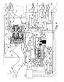
- generator lubricant is forced to circulate between generator 44 and exchanger 61' under the pressure provided by computer controlled generator lubricant pressurization pump 67 as directed by computer 60 (the same designations are used for the system components in Figure 4 as were used for similar system components in Figure 1 ).
- the lubricant enters this exchanger at the lubricant entrance upper right port thereof to pass through the tube set therein and then leave the exchanger at the lubricant exit lower left port thereof with both ports having lubricant temperature sensors.
- Coolant is again drawn from return line 70 by computer controlled pressurization coolant pump 73 under direction of computer 60 through the coolant entrance lower right port of the exchanger to pass through the chamber thereof and then leave same through the coolant exit upper left port (both ports have coolant temperature sensors) to pass through line 71 to and out of the block 36 cooling ducts of intermittent combustion engine 34.
- Computer 60 can direct coolant to bypass the chamber in exchanger 61' through a bypass arrangement, 76', connected between line 70 at the exchanger coolant entrance lower right port and line 71 at the exchanger coolant exit upper left port.
- the coolant can then be directed by computer 60 again to be sent to reenter engine 34 through bypass arrangement 75, or to enter coolant manifold line 80.
- a separate lubricant liquid-to-coolant heat exchanger, 61 ", provided for cooling the lubricant used in turbofan engine 14, does not operate in the system of Figure 4 just as does the upper half of dual lubricant liquids-to-coolant heat exchanger 61 in the system of Figure 1 .
- the engine lubricant is again forced to circulate between engine 14 and exchanger 61" under the pressure provided by computer controlled turbofan lubricant pressurization pump 63 and computer controlled scavenger pump 65 as directed by computer 60 as before, the coolant flow path therefor now differs.
- the coolant entering exchanger 61 " does not come directly thereto from the cooling devices through return line 70 to thereby be as cool as possible, but comes thereto from intermittent combustion engine 34 through pump 73, lines 74 and 80, computer controlled valve 83 and line 83', and is thus already somewhat heated.
- Such an arrangement allows operating turbofan engine at higher temperatures and so more efficiently.
- computer 60 directs engine lubricant to flow from the exit lubricant lower right port in exchanger 61 " with a lubricant temperature sensor thereat through pressurization line 62 as pressurized by computer controlled turbofan lubricant pressurization pump 63 under control of computer 60.
- the lubricant flows through further pressurization line portion 62' to the lubricant entrance port in gearbox 52. That lubricant, after providing lubrication and absorbing heat in this gearbox and engine, then returns to heat exchanger 61 " by flowing out of the gearbox lubricant exit port and through scavenger return line 64 as further pressurized by a computer controlled scavenger pump 65 also under control of computer 60.
- the lubricant flows through further scavenger return line portion 64' to the lubricant entrance upper left port of the exchanger to flow through the tube set therein to the exit lubricant port.
- Computer 60 directs the amount of coolant from manifold line 80 that is to pass into the chamber of heat exchanger 61 " for cooling this lubricant flow from turbofan engine 14 through causing computer controlled valve 83 for air-to-coolant heat exchanger 28 to suitably open. Opening of valve 83 to a selected degree admits coolant under pressure from computer controlled pressurization coolant pump 73 to flow through interconnection line 83' connected to the coolant entrance left lower port of exchanger 61 ", which has a coolant temperature sensor thereat, and then through the chamber in that exchanger.
- Computer 60 can reduce the cooling of the lubricant flow from turbofan engine 14 through opening a bypass arrangement, 76", connected to line 83' near the coolant entrance left lower port of exchanger 61 " and to line 83 " near the exchanger coolant exit upper right port to have some of the coolant bypass exchanger 61".
- the coolant flowing from line 83" into the tubes of exchanger 28 heats the air flowing past those tubes that has been forced by high pressure fan 21 into cooling duct 27 from outer part 15 of duct 11 that houses turbofan engine 14 to thereby provide added thrust as this air escapes through nozzle 29.
- the coolant thereafter exits the set of tubes in heat exchanger 28 to coolant return line 70 as in the system of Figure 1 .
Landscapes
- Engineering & Computer Science (AREA)
- Mechanical Engineering (AREA)
- General Engineering & Computer Science (AREA)
- Chemical & Material Sciences (AREA)
- Combustion & Propulsion (AREA)
- Chemical Kinetics & Catalysis (AREA)
- General Chemical & Material Sciences (AREA)
- Engine Equipment That Uses Special Cycles (AREA)
Applications Claiming Priority (1)
| Application Number | Priority Date | Filing Date | Title |
|---|---|---|---|
| US11/820,722 US7836680B2 (en) | 2007-06-20 | 2007-06-20 | Aircraft combination engines thermal management system |
Publications (2)
| Publication Number | Publication Date |
|---|---|
| EP2006493A2 true EP2006493A2 (de) | 2008-12-24 |
| EP2006493A3 EP2006493A3 (de) | 2013-04-10 |
Family
ID=39797440
Family Applications (1)
| Application Number | Title | Priority Date | Filing Date |
|---|---|---|---|
| EP08252057.8A Withdrawn EP2006493A3 (de) | 2007-06-20 | 2008-06-16 | Wärmeverwaltungssystem für Flugzeugkombinationsmotoren |
Country Status (2)
| Country | Link |
|---|---|
| US (1) | US7836680B2 (de) |
| EP (1) | EP2006493A3 (de) |
Cited By (3)
| Publication number | Priority date | Publication date | Assignee | Title |
|---|---|---|---|---|
| EP2945866A4 (de) * | 2013-01-16 | 2016-08-17 | William M Otto | Zusätzliche flugzeugschubvorrichtung und verfahren zum betrieb davon |
| EP3127814A1 (de) * | 2015-08-07 | 2017-02-08 | Pratt & Whitney Canada Corp. | Flugzeugheizungsanlage mit flüssigkeitsgekühlter brennkraftmaschine und abwärme verwendendes heizelement |
| EP4610480A1 (de) * | 2024-02-28 | 2025-09-03 | Pratt & Whitney Canada Corp. | Flugzeugkraftwerk mit wärmeverwaltungssystem |
Families Citing this family (76)
| Publication number | Priority date | Publication date | Assignee | Title |
|---|---|---|---|---|
| US8480460B2 (en) * | 2007-10-01 | 2013-07-09 | United Technologies Corporation | Cabin air supercharged aircraft internal combustion engine |
| US8307662B2 (en) * | 2009-10-15 | 2012-11-13 | General Electric Company | Gas turbine engine temperature modulated cooling flow |
| US8499544B2 (en) * | 2009-11-17 | 2013-08-06 | General Electric Company | Turbogenerator with cooling system |
| US8300412B2 (en) | 2010-09-30 | 2012-10-30 | Hamilton Sundstrand Corporation | Heat exchanger for motor controller |
| US8602717B2 (en) | 2010-10-28 | 2013-12-10 | United Technologies Corporation | Compression system for turbomachine heat exchanger |
| US8961114B2 (en) | 2010-11-22 | 2015-02-24 | General Electric Company | Integrated variable geometry flow restrictor and heat exchanger |
| US20120204814A1 (en) * | 2011-02-15 | 2012-08-16 | General Electric Company | Pulse Detonation Combustor Heat Exchanger |
| US9109464B2 (en) | 2011-08-31 | 2015-08-18 | United Technologies Corporation | Distributed lubrication system |
| US8495857B2 (en) | 2011-10-31 | 2013-07-30 | United Technologies Corporation | Gas turbine engine thermal management system |
| US9334802B2 (en) | 2011-10-31 | 2016-05-10 | United Technologies Corporation | Gas turbine engine thermal management system |
| US9222411B2 (en) | 2011-12-21 | 2015-12-29 | General Electric Company | Bleed air and hot section component cooling air system and method |
| FR2986780B1 (fr) * | 2012-02-13 | 2014-11-14 | Motorisations Aeronautiques | Dispositif d’alimentation en air d’un groupe auxiliaire de puissance d’un aeronef, aeronef |
| GB201202990D0 (en) * | 2012-02-22 | 2012-04-04 | Rolls Royce Plc | An auxiliary power system |
| US9222415B2 (en) * | 2012-03-06 | 2015-12-29 | Hamilton Sundstrand Corporation | Gas turbine engine fuel heating system |
| US9599410B2 (en) | 2012-07-27 | 2017-03-21 | General Electric Company | Plate-like air-cooled engine surface cooler with fluid channel and varying fin geometry |
| US9765694B2 (en) * | 2012-08-07 | 2017-09-19 | Unison Industries, Llc | Gas turbine engine heat exchangers and methods of assembling the same |
| EP2954212B1 (de) | 2013-02-06 | 2020-10-21 | United Technologies Corporation | Mehrzyklus-schmiersystem für einen turbinenmotor |
| EP2954185B1 (de) | 2013-02-06 | 2022-05-04 | Raytheon Technologies Corporation | Mehrzyklus-schmiersystem für einen turbinenmotor |
| US9429072B2 (en) | 2013-05-22 | 2016-08-30 | General Electric Company | Return fluid air cooler system for turbine cooling with optional power extraction |
| US9422063B2 (en) | 2013-05-31 | 2016-08-23 | General Electric Company | Cooled cooling air system for a gas turbine |
| WO2015053824A1 (en) * | 2013-10-09 | 2015-04-16 | United Technologies Corporation | Thermal management system manifold |
| US10253687B2 (en) | 2015-08-07 | 2019-04-09 | Pratt & Whitney Canada Corp. | Auxiliary power unit with electrically driven compressor |
| US10267191B2 (en) | 2015-08-07 | 2019-04-23 | Pratt & Whitney Canada Corp. | Turboprop engine assembly with combined engine and cooling exhaust |
| US10253726B2 (en) | 2015-08-07 | 2019-04-09 | Pratt & Whitney Canada Corp. | Engine assembly with combined engine and cooling exhaust |
| US10240522B2 (en) * | 2015-08-07 | 2019-03-26 | Pratt & Whitney Canada Corp. | Auxiliary power unit with combined cooling of generator |
| US10094275B2 (en) * | 2016-01-26 | 2018-10-09 | General Electric Company | Operation scheduling for optimal performance of hybrid power plants |
| US11187156B2 (en) | 2017-11-21 | 2021-11-30 | General Electric Company | Thermal management system |
| US11125165B2 (en) | 2017-11-21 | 2021-09-21 | General Electric Company | Thermal management system |
| US11725584B2 (en) | 2018-01-17 | 2023-08-15 | General Electric Company | Heat engine with heat exchanger |
| US10941706B2 (en) | 2018-02-13 | 2021-03-09 | General Electric Company | Closed cycle heat engine for a gas turbine engine |
| US11143104B2 (en) | 2018-02-20 | 2021-10-12 | General Electric Company | Thermal management system |
| US11578667B2 (en) | 2018-08-30 | 2023-02-14 | Rolls-Royce Corporation | Efficiency-based machine control |
| US11085636B2 (en) | 2018-11-02 | 2021-08-10 | General Electric Company | Fuel oxygen conversion unit |
| US11131256B2 (en) | 2018-11-02 | 2021-09-28 | General Electric Company | Fuel oxygen conversion unit with a fuel/gas separator |
| US11161622B2 (en) | 2018-11-02 | 2021-11-02 | General Electric Company | Fuel oxygen reduction unit |
| US11319085B2 (en) | 2018-11-02 | 2022-05-03 | General Electric Company | Fuel oxygen conversion unit with valve control |
| US11148824B2 (en) | 2018-11-02 | 2021-10-19 | General Electric Company | Fuel delivery system having a fuel oxygen reduction unit |
| US11577852B2 (en) | 2018-11-02 | 2023-02-14 | General Electric Company | Fuel oxygen conversion unit |
| US11447263B2 (en) | 2018-11-02 | 2022-09-20 | General Electric Company | Fuel oxygen reduction unit control system |
| US11420763B2 (en) | 2018-11-02 | 2022-08-23 | General Electric Company | Fuel delivery system having a fuel oxygen reduction unit |
| US11193671B2 (en) | 2018-11-02 | 2021-12-07 | General Electric Company | Fuel oxygen conversion unit with a fuel gas separator |
| US11186382B2 (en) | 2018-11-02 | 2021-11-30 | General Electric Company | Fuel oxygen conversion unit |
| US11851204B2 (en) | 2018-11-02 | 2023-12-26 | General Electric Company | Fuel oxygen conversion unit with a dual separator pump |
| US11015534B2 (en) | 2018-11-28 | 2021-05-25 | General Electric Company | Thermal management system |
| US11391211B2 (en) | 2018-11-28 | 2022-07-19 | General Electric Company | Waste heat recovery system |
| US10634233B1 (en) | 2018-11-29 | 2020-04-28 | Rolls-Royce Corporation | Efficiency based gearbox cooling control |
| US11162379B2 (en) * | 2019-03-15 | 2021-11-02 | Hamilton Sundstrand Corporation | Temperature control device for tail cone mounted generator |
| US10914274B1 (en) | 2019-09-11 | 2021-02-09 | General Electric Company | Fuel oxygen reduction unit with plasma reactor |
| US11774427B2 (en) | 2019-11-27 | 2023-10-03 | General Electric Company | Methods and apparatus for monitoring health of fuel oxygen conversion unit |
| US11906163B2 (en) | 2020-05-01 | 2024-02-20 | General Electric Company | Fuel oxygen conversion unit with integrated water removal |
| US11866182B2 (en) | 2020-05-01 | 2024-01-09 | General Electric Company | Fuel delivery system having a fuel oxygen reduction unit |
| US11773776B2 (en) | 2020-05-01 | 2023-10-03 | General Electric Company | Fuel oxygen reduction unit for prescribed operating conditions |
| US20220213802A1 (en) | 2021-01-06 | 2022-07-07 | General Electric Company | System for controlling blade clearances within a gas turbine engine |
| US11434824B2 (en) | 2021-02-03 | 2022-09-06 | General Electric Company | Fuel heater and energy conversion system |
| US11788470B2 (en) | 2021-03-01 | 2023-10-17 | General Electric Company | Gas turbine engine thermal management |
| US11591965B2 (en) | 2021-03-29 | 2023-02-28 | General Electric Company | Thermal management system for transferring heat between fluids |
| US12139270B2 (en) | 2021-04-19 | 2024-11-12 | General Electric Company | Aircraft thermal transport system and method |
| US12115470B2 (en) | 2021-04-27 | 2024-10-15 | General Electric Company | Fuel oxygen reduction unit |
| US12005377B2 (en) | 2021-06-15 | 2024-06-11 | General Electric Company | Fuel oxygen reduction unit with level control device |
| US11674396B2 (en) | 2021-07-30 | 2023-06-13 | General Electric Company | Cooling air delivery assembly |
| US11920500B2 (en) | 2021-08-30 | 2024-03-05 | General Electric Company | Passive flow modulation device |
| US11702958B2 (en) | 2021-09-23 | 2023-07-18 | General Electric Company | System and method of regulating thermal transport bus pressure |
| US12410752B2 (en) | 2021-09-23 | 2025-09-09 | General Electric Company | System and method of detecting an airflow fault condition |
| CN113914946A (zh) * | 2021-10-29 | 2022-01-11 | 华能上海燃机发电有限责任公司 | 一种联合循环机组的透平端轴承热控线缆冷却装置 |
| US11542870B1 (en) | 2021-11-24 | 2023-01-03 | General Electric Company | Gas supply system |
| US11692448B1 (en) | 2022-03-04 | 2023-07-04 | General Electric Company | Passive valve assembly for a nozzle of a gas turbine engine |
| US12503980B2 (en) | 2022-11-01 | 2025-12-23 | General Electric Company | Gas turbine engine |
| US12410753B2 (en) | 2022-11-01 | 2025-09-09 | General Electric Company | Gas turbine engine |
| US12392290B2 (en) | 2022-11-01 | 2025-08-19 | General Electric Company | Gas turbine engine |
| US12428992B2 (en) | 2022-11-01 | 2025-09-30 | General Electric Company | Gas turbine engine |
| US12196131B2 (en) | 2022-11-01 | 2025-01-14 | General Electric Company | Gas turbine engine |
| US12535033B2 (en) | 2022-11-01 | 2026-01-27 | General Electric Company | Gas turbine engine |
| US12398678B2 (en) | 2023-07-28 | 2025-08-26 | Rolls-Royce Corporation | Motor and motor controller thermal management features |
| US12529340B2 (en) | 2023-07-28 | 2026-01-20 | Rolls-Royce Corporation | Emergency start of a gas turbine engine |
| US12291997B1 (en) | 2024-04-30 | 2025-05-06 | General Electric Company | Variable area turbine nozzle assembly |
| US12540551B1 (en) | 2025-07-01 | 2026-02-03 | General Electric Company | Gas turbine engines including splittered airfoils |
Citations (1)
| Publication number | Priority date | Publication date | Assignee | Title |
|---|---|---|---|---|
| EP1965053A2 (de) | 2007-03-02 | 2008-09-03 | United Technologies Corporation | Kombinationsmotoren für Flugzeuge |
Family Cites Families (7)
| Publication number | Priority date | Publication date | Assignee | Title |
|---|---|---|---|---|
| US2385366A (en) * | 1938-04-19 | 1945-09-25 | Jarvis C Marble | Power plant for aircraft |
| US2356557A (en) * | 1939-12-19 | 1944-08-22 | Anxionnaz Rene | Reaction propelling device with supercharged engine |
| US2465099A (en) * | 1943-11-20 | 1949-03-22 | Allis Chalmers Mfg Co | Propulsion means comprising an internal-combustion engine and a propulsive jet |
| US4815282A (en) * | 1987-02-24 | 1989-03-28 | Teledyne Industries, Inc. | Turbocharged compund cycle ducted fan engine system |
| US8387362B2 (en) * | 2006-10-19 | 2013-03-05 | Michael Ralph Storage | Method and apparatus for operating gas turbine engine heat exchangers |
| US7485981B2 (en) * | 2007-05-09 | 2009-02-03 | United Technologies Corporation | Aircraft combination engines complemental connection and operation |
| US7690189B2 (en) * | 2007-05-09 | 2010-04-06 | United Technologies Corporation | Aircraft combination engines inlet airflow control system |
-
2007
- 2007-06-20 US US11/820,722 patent/US7836680B2/en not_active Expired - Fee Related
-
2008
- 2008-06-16 EP EP08252057.8A patent/EP2006493A3/de not_active Withdrawn
Patent Citations (1)
| Publication number | Priority date | Publication date | Assignee | Title |
|---|---|---|---|---|
| EP1965053A2 (de) | 2007-03-02 | 2008-09-03 | United Technologies Corporation | Kombinationsmotoren für Flugzeuge |
Cited By (6)
| Publication number | Priority date | Publication date | Assignee | Title |
|---|---|---|---|---|
| EP2945866A4 (de) * | 2013-01-16 | 2016-08-17 | William M Otto | Zusätzliche flugzeugschubvorrichtung und verfahren zum betrieb davon |
| EP3127814A1 (de) * | 2015-08-07 | 2017-02-08 | Pratt & Whitney Canada Corp. | Flugzeugheizungsanlage mit flüssigkeitsgekühlter brennkraftmaschine und abwärme verwendendes heizelement |
| CN108137163A (zh) * | 2015-08-07 | 2018-06-08 | 普拉特 - 惠特尼加拿大公司 | 具有液体冷却的内燃机和利用废热的加热元件的飞行器加热组件 |
| CN108137163B (zh) * | 2015-08-07 | 2021-11-09 | 普拉特-惠特尼加拿大公司 | 具有液体冷却的内燃机和利用废热的加热元件的飞行器加热组件 |
| US11214381B2 (en) | 2015-08-07 | 2022-01-04 | Pratt & Whitney Canada Corp. | Aircraft heating assembly with liquid cooled internal combustion engine and heating element using waste heat |
| EP4610480A1 (de) * | 2024-02-28 | 2025-09-03 | Pratt & Whitney Canada Corp. | Flugzeugkraftwerk mit wärmeverwaltungssystem |
Also Published As
| Publication number | Publication date |
|---|---|
| US7836680B2 (en) | 2010-11-23 |
| EP2006493A3 (de) | 2013-04-10 |
| US20080314573A1 (en) | 2008-12-25 |
Similar Documents
| Publication | Publication Date | Title |
|---|---|---|
| US7836680B2 (en) | Aircraft combination engines thermal management system | |
| US7690188B2 (en) | Combination engines for aircraft | |
| US11746701B2 (en) | Bleed expander cooling with turbine | |
| EP3623603B1 (de) | Hybridexpanderzyklus mit turbogenerator und gekühlter leistungselektronik | |
| US8480460B2 (en) | Cabin air supercharged aircraft internal combustion engine | |
| US7485981B2 (en) | Aircraft combination engines complemental connection and operation | |
| US7690189B2 (en) | Aircraft combination engines inlet airflow control system | |
| EP1992788B1 (de) | Beförderungssystem für mehrere Einströmungslüfte in Flugzeugkombinationsmotoren | |
| EP3992447B1 (de) | Flugzeugtriebwerk mit überkritischem co2-wärmemotor | |
| EP4012168A1 (de) | Verfahren zum betrieb eines flugzeugmotors und brennstoffsystem mit mehreren brennstoffarten | |
| US12351322B2 (en) | Aircraft power plant | |
| FR2978728A1 (fr) | Architecture de propulsion d'aeronef integrant un systeme de recuperation d'energie | |
| CN108137163A (zh) | 具有液体冷却的内燃机和利用废热的加热元件的飞行器加热组件 | |
| EP4303418B1 (de) | Hybride elektrische energie für turbinenmotoren mit wasserstoffbrennstoffsystemen | |
| EP4012169A1 (de) | Verfahren zum betrieb eines flugzeugmotors und brennstoffsystem mit mehreren brennstoffarten | |
| EP1992811B1 (de) | Abgasschubrückgewinnung in Flugzeugkombinationstriebwerken | |
| RU2375219C1 (ru) | Атомный газотурбовоз и двигательная установка атомного газотурбовоза | |
| EP4726188A2 (de) | Verbesserter rückgewinnungszyklus für einen turbinenmotor eines flugzeugtriebwerks | |
| RU2336429C1 (ru) | Атомный газотурбинный двигатель |
Legal Events
| Date | Code | Title | Description |
|---|---|---|---|
| PUAI | Public reference made under article 153(3) epc to a published international application that has entered the european phase |
Free format text: ORIGINAL CODE: 0009012 |
|
| AK | Designated contracting states |
Kind code of ref document: A2 Designated state(s): AT BE BG CH CY CZ DE DK EE ES FI FR GB GR HR HU IE IS IT LI LT LU LV MC MT NL NO PL PT RO SE SI SK TR |
|
| AX | Request for extension of the european patent |
Extension state: AL BA MK RS |
|
| PUAL | Search report despatched |
Free format text: ORIGINAL CODE: 0009013 |
|
| AK | Designated contracting states |
Kind code of ref document: A3 Designated state(s): AT BE BG CH CY CZ DE DK EE ES FI FR GB GR HR HU IE IS IT LI LT LU LV MC MT NL NO PL PT RO SE SI SK TR |
|
| AX | Request for extension of the european patent |
Extension state: AL BA MK RS |
|
| RIC1 | Information provided on ipc code assigned before grant |
Ipc: F02K 3/06 20060101ALI20130306BHEP Ipc: F01D 25/12 20060101ALI20130306BHEP Ipc: F02C 6/08 20060101ALI20130306BHEP Ipc: F02K 5/02 20060101ALI20130306BHEP Ipc: F02K 3/115 20060101ALI20130306BHEP Ipc: F02C 7/18 20060101ALI20130306BHEP Ipc: F02C 7/224 20060101ALI20130306BHEP Ipc: F01D 13/02 20060101ALI20130306BHEP Ipc: F01D 15/10 20060101AFI20130306BHEP Ipc: F02C 6/10 20060101ALI20130306BHEP |
|
| 17P | Request for examination filed |
Effective date: 20131010 |
|
| RBV | Designated contracting states (corrected) |
Designated state(s): AT BE BG CH CY CZ DE DK EE ES FI FR GB GR HR HU IE IS IT LI LT LU LV MC MT NL NO PL PT RO SE SI SK TR |
|
| AKX | Designation fees paid |
Designated state(s): BE DE FR GB |
|
| GRAP | Despatch of communication of intention to grant a patent |
Free format text: ORIGINAL CODE: EPIDOSNIGR1 |
|
| INTG | Intention to grant announced |
Effective date: 20140102 |
|
| STAA | Information on the status of an ep patent application or granted ep patent |
Free format text: STATUS: THE APPLICATION IS DEEMED TO BE WITHDRAWN |
|
| 18D | Application deemed to be withdrawn |
Effective date: 20140513 |