EP2006471A1 - Wind turbine tower and method for constructing a wind turbine tower - Google Patents
Wind turbine tower and method for constructing a wind turbine tower Download PDFInfo
- Publication number
- EP2006471A1 EP2006471A1 EP07012103A EP07012103A EP2006471A1 EP 2006471 A1 EP2006471 A1 EP 2006471A1 EP 07012103 A EP07012103 A EP 07012103A EP 07012103 A EP07012103 A EP 07012103A EP 2006471 A1 EP2006471 A1 EP 2006471A1
- Authority
- EP
- European Patent Office
- Prior art keywords
- flat plates
- wind turbine
- plates
- segments
- tower
- Prior art date
- Legal status (The legal status is an assumption and is not a legal conclusion. Google has not performed a legal analysis and makes no representation as to the accuracy of the status listed.)
- Granted
Links
Images


Classifications
-
- E—FIXED CONSTRUCTIONS
- E04—BUILDING
- E04H—BUILDINGS OR LIKE STRUCTURES FOR PARTICULAR PURPOSES; SWIMMING OR SPLASH BATHS OR POOLS; MASTS; FENCING; TENTS OR CANOPIES, IN GENERAL
- E04H12/00—Towers; Masts or poles; Chimney stacks; Water-towers; Methods of erecting such structures
- E04H12/02—Structures made of specified materials
- E04H12/08—Structures made of specified materials of metal
- E04H12/085—Details of flanges for tubular masts
-
- F—MECHANICAL ENGINEERING; LIGHTING; HEATING; WEAPONS; BLASTING
- F03—MACHINES OR ENGINES FOR LIQUIDS; WIND, SPRING, OR WEIGHT MOTORS; PRODUCING MECHANICAL POWER OR A REACTIVE PROPULSIVE THRUST, NOT OTHERWISE PROVIDED FOR
- F03D—WIND MOTORS
- F03D13/00—Assembly, mounting or commissioning of wind motors; Arrangements specially adapted for transporting wind motor components
- F03D13/20—Arrangements for mounting or supporting wind motors; Masts or towers for wind motors
-
- E—FIXED CONSTRUCTIONS
- E02—HYDRAULIC ENGINEERING; FOUNDATIONS; SOIL SHIFTING
- E02B—HYDRAULIC ENGINEERING
- E02B17/00—Artificial islands mounted on piles or like supports, e.g. platforms on raisable legs or offshore constructions; Construction methods therefor
- E02B2017/0056—Platforms with supporting legs
- E02B2017/0073—Details of sea bottom engaging footing
- E02B2017/0078—Suction piles, suction cans
-
- F—MECHANICAL ENGINEERING; LIGHTING; HEATING; WEAPONS; BLASTING
- F05—INDEXING SCHEMES RELATING TO ENGINES OR PUMPS IN VARIOUS SUBCLASSES OF CLASSES F01-F04
- F05B—INDEXING SCHEME RELATING TO WIND, SPRING, WEIGHT, INERTIA OR LIKE MOTORS, TO MACHINES OR ENGINES FOR LIQUIDS COVERED BY SUBCLASSES F03B, F03D AND F03G
- F05B2230/00—Manufacture
-
- F—MECHANICAL ENGINEERING; LIGHTING; HEATING; WEAPONS; BLASTING
- F05—INDEXING SCHEMES RELATING TO ENGINES OR PUMPS IN VARIOUS SUBCLASSES OF CLASSES F01-F04
- F05B—INDEXING SCHEME RELATING TO WIND, SPRING, WEIGHT, INERTIA OR LIKE MOTORS, TO MACHINES OR ENGINES FOR LIQUIDS COVERED BY SUBCLASSES F03B, F03D AND F03G
- F05B2240/00—Components
- F05B2240/90—Mounting on supporting structures or systems
- F05B2240/91—Mounting on supporting structures or systems on a stationary structure
- F05B2240/912—Mounting on supporting structures or systems on a stationary structure on a tower
-
- Y—GENERAL TAGGING OF NEW TECHNOLOGICAL DEVELOPMENTS; GENERAL TAGGING OF CROSS-SECTIONAL TECHNOLOGIES SPANNING OVER SEVERAL SECTIONS OF THE IPC; TECHNICAL SUBJECTS COVERED BY FORMER USPC CROSS-REFERENCE ART COLLECTIONS [XRACs] AND DIGESTS
- Y02—TECHNOLOGIES OR APPLICATIONS FOR MITIGATION OR ADAPTATION AGAINST CLIMATE CHANGE
- Y02E—REDUCTION OF GREENHOUSE GAS [GHG] EMISSIONS, RELATED TO ENERGY GENERATION, TRANSMISSION OR DISTRIBUTION
- Y02E10/00—Energy generation through renewable energy sources
- Y02E10/70—Wind energy
- Y02E10/72—Wind turbines with rotation axis in wind direction
-
- Y—GENERAL TAGGING OF NEW TECHNOLOGICAL DEVELOPMENTS; GENERAL TAGGING OF CROSS-SECTIONAL TECHNOLOGIES SPANNING OVER SEVERAL SECTIONS OF THE IPC; TECHNICAL SUBJECTS COVERED BY FORMER USPC CROSS-REFERENCE ART COLLECTIONS [XRACs] AND DIGESTS
- Y02—TECHNOLOGIES OR APPLICATIONS FOR MITIGATION OR ADAPTATION AGAINST CLIMATE CHANGE
- Y02E—REDUCTION OF GREENHOUSE GAS [GHG] EMISSIONS, RELATED TO ENERGY GENERATION, TRANSMISSION OR DISTRIBUTION
- Y02E10/00—Energy generation through renewable energy sources
- Y02E10/70—Wind energy
- Y02E10/728—Onshore wind turbines
-
- Y—GENERAL TAGGING OF NEW TECHNOLOGICAL DEVELOPMENTS; GENERAL TAGGING OF CROSS-SECTIONAL TECHNOLOGIES SPANNING OVER SEVERAL SECTIONS OF THE IPC; TECHNICAL SUBJECTS COVERED BY FORMER USPC CROSS-REFERENCE ART COLLECTIONS [XRACs] AND DIGESTS
- Y02—TECHNOLOGIES OR APPLICATIONS FOR MITIGATION OR ADAPTATION AGAINST CLIMATE CHANGE
- Y02P—CLIMATE CHANGE MITIGATION TECHNOLOGIES IN THE PRODUCTION OR PROCESSING OF GOODS
- Y02P70/00—Climate change mitigation technologies in the production process for final industrial or consumer products
- Y02P70/50—Manufacturing or production processes characterised by the final manufactured product
Definitions
- the present invention relates to a wind turbine tower and a method for constructing a wind turbine tower.
- Wind turbine towers especially tubular steel towers for large wind turbines, are large in diameter and weight. This may cause difficulties concerning the transportation of a tower to the wind farm and the used infrastructure.
- the steel towers for wind turbines are produced as sections in shops and the sections are then transported to the place of installation.
- the towers are typically constructed of a number of sections which have a cylindrical or conical shape.
- the problem has been solved by dimensioning, by the use of hybrid towers or by the use of modular towers. Dimensioning accepts the height and width restrictions of transportation routes and uses the restrictions as a design basis. This means in practice that the external tower diameter is fixed at a certain maximum value, typically 4.2 metres. When the diameter is fixed, then the wall thickness is dimensioned to provide the necessary stiffness and strength. For large turbines and tall towers this will typically lead to significantly higher weight. This causes higher costs compared with when no diameter restrictions are applied.
- a hybrid solution In a hybrid solution the problem is circumvented by extending the concrete foundations significantly above ground level, for example, as a cylindrical structure of, for instance, 10 metres height. This increases the effective hub height of a wind turbine where the tower design is not significantly influenced by a diameter restriction. However, above a certain practical height an extended foundation is expensive. Compared with a diameter restricted tower, a hybrid solution tower reaches an additional height of perhaps 15 metres.
- the inventive wind turbine tower comprises a number of segments with a polygonal cross section.
- Each segment comprises a number of flat plates which are connected to each other to form the polygonal cross section.
- the cross section of the segments may be a regular polygon, which means that the angle between adjacent flat plates has the same value.
- the cross section of the segments may be an irregular polygon, which means that the angle between adjacent flat plates varies.
- the segments may be connected to each other by means of splice plates, flanges, bolts, nuts, bolt extensions, washers, etc.
- flanges which are connected to each other inside the tower avoids a tightening of bolts from the outside of the tower.
- the flange connection may further comprise flanges divided into several parts which are then bolted together alternately. This means that flanges with a very large cross section can be avoided.
- Several segments can be bolted together with splice plates and form an element which may have a flange at each end, making it possible to lift each element into place to form a complete tower.
- the flat plates can also be connected to each other by means of splice plates, flanges, bolts, nuts, bolt extensions, washers, etc. Furthermore, the flat plates can be cut using plasma, oxygen/gas or a laser.
- flat plates minimises the manufacturing costs by eliminating the rolling, bending and/or welding processes.
- flat plates can be delivered in cut condition by almost any steel mill and can be transported on standard truck trailers, which increases the availability of transportation equipment.
- Flat plates can be delivered at length up to 14 metres, which is a possible length of a segment.
- flat plates are easy to surface treat by automatic blasting and surface treatment facilities so as to increase, for example, the resistance to wear and/or corrosion.
- the splice plates may be connected to the flat plates by means of bolts or nuts. It is advantageous if the splice plates which are used for connecting the flat plates to each other are bent.
- the flat plates as well as the splice plates can be made of steel or of rust resistant steel to make surface treatment redundant. Further, the flat plates and/or the splice plates can be pre-treated with friction creating material on the joining surfaces. For example, spray metallising and surface treatment with, for instance, barrier creating paint, can be applied.
- the flat plates may have a rectangular or trapezoid shape.
- the segments and the tower will have a cylindrical appearance.
- the segments and the tower will have a conical appearance.
- the flat plate has a flat surface.
- corrugated plates can be used as flat plates.
- the flat plates may advantageously have a width of 2.5 to 3 metres and a length of 10 to 14 metres.
- the joint between two flat plates or between a flat plate and a splice plate can comprise a seal strip or a compound to prevent water and dust from invading the tower. It is also possible to seal the gap between the flat plates if this is considered necessary to improve the visual appearance.
- Each segment of the inventive wind turbine tower comprises at least 3 flat plates.
- a tower segment can have any number of flat plates greater than 3, for instance, 6, 8 or 10 flat plates.
- the whole wind turbine tower, or at least a large diameter bottom section of the tower, may comprise the inventive segments. In other words, it is possible to combine the inventive wind turbine tower segments with state of the art wind turbine tower constructions.
- the splice plates and/or the assembly of these with flat plates can be used as fixing devices for internal components in the tower such as ladders, cable ladders, cable supports, platforms and electrical boxes. These components can be positioned and fixed when the individual segments are fitted together. At least one splice plate can comprise a fixing device. It is advantageous to use splice plates with bolts especially for fixing ladder brackets, platform brackets, lift brackets or cable brackets.
- the inventive method for constructing a wind turbine tower which comprises segments assembled of flat plates is characterised in that the flat plates are connected to each other to form segments with a polygonal cross section and the segments are connected to each other to form the tower.
- the flat plates and/or segments may be connected to each other by means of splice plates or flanges.
- the use of flat plates, for instance flat steel plates, for constructing a wind turbine tower allows it to assemble the segments and the tower as close to the place of installation as possible thus limiting the transport distance of tower segments with large cross sections.
- the flat plates and/or the splice plates can be pre-treated on the joining surfaces with a friction creating material, for instance by spray metallising and surface treatment with, for example, a barrier creating paint.
- the flat plate and/or the segments can be connected to each other in a horizontal position. It is advantageous if the flat plates and/or the segments are placed in a predefined position by a rotation tool for connection to each other.
- Each segment or the whole tower may be erected after its assembly. The assembling and the erection can advantageously take place at the place of installation in the field of the wind turbine tower.
- the erection of the tower or a segment can be realised by use of a crane or any other lifting device.
- the advantage of the present invention is that it minimises the total costs of large wind turbine towers by reducing the total costs of production, transportation and installation.
- flat plates for instance, flat steel plates, avoids any rolling, bending and/or welding of the steel plates. Thereby, manufacturing costs are saved and the fatigue capability is improved.
- flat plates allow the use of standard transportation equipment, for instance ordinary truck trailers, for transportation of the parts of the tower structure from the steel supplier to the installation site.
- the present invention makes it possible to assemble the components for the tower structure at the installation site in an efficient and simple way.
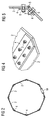
- FIG. 1 schematically shows part of an inventive wind turbine tower in a frontal view.
- the wind turbine tower comprises segments 1 which are connected to each other by means of bolts 3 and splice plates.
- the lowermost segment 1 includes a door 19, a manhole or the like to allow entering the interior of the tower after it is erected.
- Each segment 1 comprises a number of flat plates 2.
- the flat plates 2 can have a trapezoid shape, as shown in Fig. 1 or, alternatively, a rectangular shape. They can be made of steel or rust resistant steel. Preferably the flat plates 2 have a width of 2.5 to 3 metres and a length of 10 to 14 metres. As an alternative to the flat shape of the flat plates 2 the flat plates 2 can also be corrugated plates.
- the flat plates 2 are also connected to each other by means of bolts 3 and splice plates. Instead of splice plates or bolts also flanges, nuts, bolt extensions or washers can be used.
- Figure 2 schematically shows a sectional view along the A-A direction of the wind turbine tower which is shown in Figure 1 .
- the flat plates 2 are connected to each other to form a polygonal cross section.
- eight flat plates 2 form an octahedral cross section.
- six or ten or any other number of flat plates 2 greater than three can be used to form a polygonal cross section.
- the flat plates 2 are connected to each other by means of splice plates 4.
- the splice plates 4 are bent to form an angle between the connected flat plates 2. The angle is adapted to the polygonal cross section to be formed by the plates.
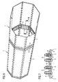
- Figure 3 schematically shows a segment 1 of an inventive wind turbine tower in a horizontal position in a perspective view.
- the segment 1 has an octahedral cross section.
- the used flat plates 2 are connected to each other by means of splice plates 4.
- the splice plates 4 are fixed to the flat plates 2 by bolts 3.
- FIG. 4 schematically shows again an enlarged section of a connection between two flat plates 2 by means of a bent splice plate 4 in a perspective view.
- Each flat plate 2 is connected to the splice plate 4 by means of bolts 3 and the splice plate 4 connects the two flat plates to each other.
- the flat plates 2 and the splice plates 4 can be pre-treated with friction creating material on the jointing surfaces.
- the holes in the flat plates 2 and the splice plates 4 for the bolts can generally be cut by means of plasma, oxygen/gas or a laser.
- Figure 5 schematically shows a sectional view along the B-B direction in Figure 1 .
- the splice plate 4 is connected to each flat plate 2 by means of a bolt 3.
- the bolt 3 is fixed by a screw nut 8.
- a sealed strip 5 is visible at the joint between the two flat plates 2 to prevent water and dust to invade the turbine tower and to improve the visual appearance of the tower.
- a seal strip a compound can also be used.
- Figure 6 schematically shows the connection between two segments 1 by means of splice plates 4 in a horizontal position in a perspective view.
- the segments 1 are assembled of flat plates 2.
- the splice plates 4 are connected to the flat plates 2 of the segment 1 by means of bolts 3.
- Figure 7 schematically shows the connection between two segments 1 of the inventive wind turbine tower in a sectional view along C-C direction in Figure 1 and Figure 6 .
- Figure 5 two flat plates 2 which belong to two different segments 1.
- the two segments 1 are connected to each other by a splice plate 4 which is not bent.
- the flat plates 2 and the splice plate 4 comprise holes 9 through which bolts 3 connect the flat plates 2 and the splice plates 4 to each other.
- the bolts 3 are fixed by screw nuts 8 and bolt extensions 6.
- the whole wind turbine tower can be constructed of the described segments 1.
- a part of the tower for instance the large diameter bottom section, can be constructed of the described segments 1.
- the splice plates 4 inside the tower can comprise fixing devices, for instance ladder brackets, platform brackets, lift brackets, cable brackets.
- FIG 8 schematically shows as an alternative to Figure 6 the connection between two segments 1 by means of flanges 7 in a horizontal position in a perspective view.
- Each segment 1 has an octahedral cross section and comprises eight flat plates 2.
- Each segment 1 is connected to flanges 7 by means of bolts 3.
- the flanges 7 of different segments 1 are fixed to each other by bolts 3 which can be tightened from the inside of the segment 1. This allows an easier mounting of the tower than in the case of using splice plates for connecting segments, which was described in the first embodiment.
- Figure 9 shows a sectional view along the C-C direction of Figure 8 .
- two flat plates 2 which belong to different segments 1.
- the two flat plates 2 are now connected by means of flanges 7.
- a flange 7 is connected to each flat plate 2 by means of bolts 3.
- Two other bolts 3 connect a flat plate 2 and a flange 7 by means of bolt extensions 6 and screw nuts 8.
- the two flanges 7 are connected to each other by a bolt 3 and a screw nut 8.
- the advantage of using flanges 7 is that they provide a very stable connection between the flat plates 2 or, more precisely, the segments 1.
- the flat plates 2 of a segment 1 can also be connected to each other by flanges 7.
- any combination of splice plates 4 and flanges 7 for connecting the flat plates 2 and the segments 1 are possible, for example splice plates 4 for connecting the flat plates 2 and flanges 7 for connecting the segments 1.
- the segments 1 can be connected to each other by flanges 7 which are located only on parts of the short side of the flat plates 2 where no splice plate 4, which connects the flat plates 2 to each other, is placed.
- An alternative is it to connect the segments 1 around the whole circumference of their cross section by flanges 7 to each other.
- the flat plates 2 of a segment 1 may be connected to each other by splice plates 4 along only parts of their long side, where no flange 7, which connects the segments 1 to each other, is located.
- FIG. 10 Rails 16 with transport carts 15, a crane 13, a plate storage 14, carriages 10 and a rotation tool 11.
- transport carts 15 which is sketched on the right side of Figure 10 .
- the flat plates 2 may be lifted from the transport cart 15 by a crane 13 and stored in a plate storage 14.
- any other lifting device may be used, for example a magnet or a vacuum lifting device.
- the rotation tool 11 comprises two parts, one of which is schematically shown in Figure 11 .
- the casing 17 of the rotation tool 11 is visible.
- the casing 17 comprises an opening 18 with a polygonal cross section.
- the opening 18 may comprise tools for fixing flat plates 2 and/or splice plates 4 to facilitate the assembly of flat plates 2 and splice plates 4 to segments 1.
- the rotation tool 11 may be covered with a tent 12, as it is shown in Figure 10 .
- the rotation tool 11 allows the flat plates 2 to be connected to the splice plates in a horizontal position.
- the rotation tool 11 can be rotated so that the next flat plate 2 can be assembled to the first two flat plates 2 also in a horizontal position.
- the mounting of the last flat plate 2 and the last splice plate 4 is sketched in Figure 12 in a sectional view.
- Figure 12 One can see in Figure 12 seven already assembled flat plates 2 and splice plates 4 and the last flat plate 2 and splice plate 4 which is transported to the others by a carriage 10.
- the used rotation tool 11 comprises a turning apparatus which can be positioned vertically for attachment of the flat plates 2 and subsequently rotate freely to the next position.
- the completely assembled segment 1 can then be transported by rail 16 further from where the segments 1 are assembled. This is shown on the left side of Figure 10 . After assembling the tower it is possible to lift the tower up by means of a crane, for instance.
- the inventive wind turbine tower may be constructed of flat steel plates 2 with holes 9 cut for assembly with splice plates 4.
- the advantage is that the cutting of the plate and holes can be handled by the steel plate supplier.
- the construction of the wind turbine tower at the installation site using flat plates 4 allows it to use a steel plate supplier close to the place of installation. This makes it possible to avoid the limitations related to using the limited number of suppliers worldwide, who are experienced in producing the circular tubular towers and who are very much in demand in the wind turbine industry.
- the flat plates 4 can be sandblasted and surface treated before being transported to the assembly site.
- a standard plate size for example a width of 2.5 metres and a length of 10 to 14 metres, they can be transported to the place of assembly on standard truck trailers which are cost efficient.
- the invention has the following advantages: the flat plates 2 can be delivered in cut condition by any steel mill. They are easy to surface treat in automatic blasting and surface treatment facilities.
- the flat plates 4 are easy to transport on standard truck trailers which increases the availability of transportation equipment. Further, the flat plates 4 minimise the manufacturing costs by eliminating the rolling and welding processes necessary for normal tubular towers.
- the flat plates 4 can be bolted together with splice plates 4 and flanges 7. This eliminates the welding process and subsequent control of welds. Flat plates without welding have the best possible fatigue properties.
- flat plates can be easily assembled in various cross sections of towers, for instance hexagonal cross sections etc. This reduces the risk of buckling of the tower shells.
- the flat plates 2 can be delivered at length of up to 14 metres which is therefore the maximum possible length of a segment 1.
Abstract
Description
- The present invention relates to a wind turbine tower and a method for constructing a wind turbine tower.
- Wind turbine towers, especially tubular steel towers for large wind turbines, are large in diameter and weight. This may cause difficulties concerning the transportation of a tower to the wind farm and the used infrastructure. Usually, the steel towers for wind turbines are produced as sections in shops and the sections are then transported to the place of installation. The towers are typically constructed of a number of sections which have a cylindrical or conical shape.
- In the wind industry the requirements for larger turbines have resulted in corresponding requirements for larger wind turbine towers. Larger wind turbine towers have typically lead to larger tower section diameters and longer and heavier tower sections. The dimensions of tall towers for large wind turbine have reached limits defined by the infrastructure of various countries. The limiting aspects are typically physical limits such as free height under bridges and tunnels, allowable weights or the turning radii of roundabouts.
- The increasing number of turbines in large wind projects has also caused difficulties since the equipment which is needed to transport the largest tower sections by road or by rail is highly specialised and is not found in the quantities necessary for the present number of transportations. Consequently, when a large number of projects require a substantial amount of transportation time by road, the availability of special equipment may become difficult in the project phase.
- The problem has been solved by dimensioning, by the use of hybrid towers or by the use of modular towers. Dimensioning accepts the height and width restrictions of transportation routes and uses the restrictions as a design basis. This means in practice that the external tower diameter is fixed at a certain maximum value, typically 4.2 metres. When the diameter is fixed, then the wall thickness is dimensioned to provide the necessary stiffness and strength. For large turbines and tall towers this will typically lead to significantly higher weight. This causes higher costs compared with when no diameter restrictions are applied.
- In a hybrid solution the problem is circumvented by extending the concrete foundations significantly above ground level, for example, as a cylindrical structure of, for instance, 10 metres height. This increases the effective hub height of a wind turbine where the tower design is not significantly influenced by a diameter restriction. However, above a certain practical height an extended foundation is expensive. Compared with a diameter restricted tower, a hybrid solution tower reaches an additional height of perhaps 15 metres.
- A wide range of modular towers are well known in literature and in practice. Using a longitudinal split such solutions overcome the dimensional restrictions on transportation. However, difficulties occur in the assembly and the complexity of the modular elements.
- It is an objective of the present invention to provide an advantageous wind turbine tower which is not limited by transportation restrictions. It is a further objective to provide a method for constructing such a wind turbine tower.
- These objectives are solved by a wind turbine tower as claimed in claim 1 and a method for constructing a wind turbine tower as claimed in
claim 12. The depending claims define further developments of the invention. - The inventive wind turbine tower comprises a number of segments with a polygonal cross section. Each segment comprises a number of flat plates which are connected to each other to form the polygonal cross section. The cross section of the segments may be a regular polygon, which means that the angle between adjacent flat plates has the same value. Alternatively, the cross section of the segments may be an irregular polygon, which means that the angle between adjacent flat plates varies. The segments may be connected to each other by means of splice plates, flanges, bolts, nuts, bolt extensions, washers, etc.
- The use of flanges which are connected to each other inside the tower avoids a tightening of bolts from the outside of the tower. The flange connection may further comprise flanges divided into several parts which are then bolted together alternately. This means that flanges with a very large cross section can be avoided. Several segments can be bolted together with splice plates and form an element which may have a flange at each end, making it possible to lift each element into place to form a complete tower.
- The flat plates can also be connected to each other by means of splice plates, flanges, bolts, nuts, bolt extensions, washers, etc. Furthermore, the flat plates can be cut using plasma, oxygen/gas or a laser.
- Compared to the known state of the art modular tower solutions, which typically require rolling, bending and/or welding of the steel plates which leads to added manufacturing costs, the use of flat plates minimises the manufacturing costs by eliminating the rolling, bending and/or welding processes. Furthermore, flat plates can be delivered in cut condition by almost any steel mill and can be transported on standard truck trailers, which increases the availability of transportation equipment. Flat plates can be delivered at length up to 14 metres, which is a possible length of a segment. Moreover, flat plates are easy to surface treat by automatic blasting and surface treatment facilities so as to increase, for example, the resistance to wear and/or corrosion.
- It is advantageous to use splice plates to connect the segments and also the flat plates to each other. Flat plates bolted together with splice plates or flanges eliminate the welding process and subsequent control of welds. Further, flat plates without welding have the best possible fatigue properties. Moreover, the flat plates can be easily assembled into various cross sections of towers and in this way reduce the risk of buckling of the tower shells.
- The splice plates may be connected to the flat plates by means of bolts or nuts. It is advantageous if the splice plates which are used for connecting the flat plates to each other are bent. The flat plates as well as the splice plates can be made of steel or of rust resistant steel to make surface treatment redundant. Further, the flat plates and/or the splice plates can be pre-treated with friction creating material on the joining surfaces. For example, spray metallising and surface treatment with, for instance, barrier creating paint, can be applied.
- Generally the flat plates may have a rectangular or trapezoid shape. In the case of a rectangular shape of the flat plates, the segments and the tower will have a cylindrical appearance. In the case of a trapezoid shape of the flat plates, the segments and the tower will have a conical appearance.
- Moreover, it is not necessary that the flat plate has a flat surface. Also corrugated plates can be used as flat plates. The flat plates may advantageously have a width of 2.5 to 3 metres and a length of 10 to 14 metres. The joint between two flat plates or between a flat plate and a splice plate can comprise a seal strip or a compound to prevent water and dust from invading the tower. It is also possible to seal the gap between the flat plates if this is considered necessary to improve the visual appearance.
- Each segment of the inventive wind turbine tower comprises at least 3 flat plates. However a tower segment can have any number of flat plates greater than 3, for instance, 6, 8 or 10 flat plates. The whole wind turbine tower, or at least a large diameter bottom section of the tower, may comprise the inventive segments. In other words, it is possible to combine the inventive wind turbine tower segments with state of the art wind turbine tower constructions.
- The splice plates and/or the assembly of these with flat plates can be used as fixing devices for internal components in the tower such as ladders, cable ladders, cable supports, platforms and electrical boxes. These components can be positioned and fixed when the individual segments are fitted together. At least one splice plate can comprise a fixing device. It is advantageous to use splice plates with bolts especially for fixing ladder brackets, platform brackets, lift brackets or cable brackets.
- The inventive method for constructing a wind turbine tower which comprises segments assembled of flat plates is characterised in that the flat plates are connected to each other to form segments with a polygonal cross section and the segments are connected to each other to form the tower. The flat plates and/or segments may be connected to each other by means of splice plates or flanges. The use of flat plates, for instance flat steel plates, for constructing a wind turbine tower allows it to assemble the segments and the tower as close to the place of installation as possible thus limiting the transport distance of tower segments with large cross sections.
- The flat plates and/or the splice plates can be pre-treated on the joining surfaces with a friction creating material, for instance by spray metallising and surface treatment with, for example, a barrier creating paint.
- The flat plate and/or the segments can be connected to each other in a horizontal position. It is advantageous if the flat plates and/or the segments are placed in a predefined position by a rotation tool for connection to each other. Each segment or the whole tower may be erected after its assembly. The assembling and the erection can advantageously take place at the place of installation in the field of the wind turbine tower. The erection of the tower or a segment can be realised by use of a crane or any other lifting device.
- The advantage of the present invention is that it minimises the total costs of large wind turbine towers by reducing the total costs of production, transportation and installation. Especially the use of flat plates, for instance, flat steel plates, avoids any rolling, bending and/or welding of the steel plates. Thereby, manufacturing costs are saved and the fatigue capability is improved. Further, flat plates allow the use of standard transportation equipment, for instance ordinary truck trailers, for transportation of the parts of the tower structure from the steel supplier to the installation site. The present invention makes it possible to assemble the components for the tower structure at the installation site in an efficient and simple way.
- Further features, properties and advantages of the present invention will become clear from the following description of embodiments in conjunction with the accompanying drawings.
-
Fig. 1 schematically shows a part of an inventive wind turbine tower in a frontal view. -
Fig. 2 schematically shows a sectional view along the A-A direction of the inventive wind turbine tower which is shown inFigure 1 . -
Fig. 3 schematically shows a segment of an inventive wind turbine tower in a horizontal position in a perspective view. -
Fig. 4 schematically shows the connection between two flat plates by means of a splice plate in a perspective view. -
Fig. 5 schematically shows a sectional view along the B-B direction inFigure 1 . -
Fig. 6 schematically shows the connection between two segments by means of splice plates in a horizontal position in a perspective view. -
Fig. 7 schematically shows a sectional view along the C-C direction inFigure 1 . -
Fig. 8 schematically shows the connection between two segments by means of flanges in a horizontal position in a perspective view. -
Fig. 9 schematically shows an alternative sectional view along C-C inFigure 1 . -
Fig. 10 schematically shows an assembly site close to an installation site of an inventive wind turbine tower. -
Fig. 11 schematically shows a rotation tool in a perspective view. -
Fig. 12 schematically shows the assembling of flat plates to a segment in a sectional view. - A first embodiment of the inventive wind turbine tower will now be described with respect to
Figures 1 to 7 .Figure 1 schematically shows part of an inventive wind turbine tower in a frontal view. The wind turbine tower comprises segments 1 which are connected to each other by means ofbolts 3 and splice plates. The lowermost segment 1 includes adoor 19, a manhole or the like to allow entering the interior of the tower after it is erected. - Each segment 1 comprises a number of
flat plates 2. Theflat plates 2 can have a trapezoid shape, as shown inFig. 1 or, alternatively, a rectangular shape. They can be made of steel or rust resistant steel. Preferably theflat plates 2 have a width of 2.5 to 3 metres and a length of 10 to 14 metres. As an alternative to the flat shape of theflat plates 2 theflat plates 2 can also be corrugated plates. Theflat plates 2 are also connected to each other by means ofbolts 3 and splice plates. Instead of splice plates or bolts also flanges, nuts, bolt extensions or washers can be used. -
Figure 2 schematically shows a sectional view along the A-A direction of the wind turbine tower which is shown inFigure 1 . One can see inFigure 2 that theflat plates 2 are connected to each other to form a polygonal cross section. In the present embodiment eightflat plates 2 form an octahedral cross section. Instead of eightflat plates 2 also six or ten or any other number offlat plates 2 greater than three can be used to form a polygonal cross section. Theflat plates 2 are connected to each other by means ofsplice plates 4. Thesplice plates 4 are bent to form an angle between the connectedflat plates 2. The angle is adapted to the polygonal cross section to be formed by the plates. -
Figure 3 schematically shows a segment 1 of an inventive wind turbine tower in a horizontal position in a perspective view. One can see inFigure 3 eightflat plates 4 which form a segment 1. The segment 1 has an octahedral cross section. The usedflat plates 2 are connected to each other by means ofsplice plates 4. Thesplice plates 4 are fixed to theflat plates 2 bybolts 3. -
Figure 4 schematically shows again an enlarged section of a connection between twoflat plates 2 by means of abent splice plate 4 in a perspective view. Eachflat plate 2 is connected to thesplice plate 4 by means ofbolts 3 and thesplice plate 4 connects the two flat plates to each other. Theflat plates 2 and thesplice plates 4 can be pre-treated with friction creating material on the jointing surfaces. The holes in theflat plates 2 and thesplice plates 4 for the bolts can generally be cut by means of plasma, oxygen/gas or a laser. -
Figure 5 schematically shows a sectional view along the B-B direction inFigure 1 . One can see inFigure 3 twoflat plates 2 which are connected to each other by means of abent splice plate 4. Thesplice plate 4 is connected to eachflat plate 2 by means of abolt 3. Thebolt 3 is fixed by ascrew nut 8. Further, a sealedstrip 5 is visible at the joint between the twoflat plates 2 to prevent water and dust to invade the turbine tower and to improve the visual appearance of the tower. Instead of a seal strip a compound can also be used. -
Figure 6 schematically shows the connection between two segments 1 by means ofsplice plates 4 in a horizontal position in a perspective view. The segments 1 are assembled offlat plates 2. Thesplice plates 4 are connected to theflat plates 2 of the segment 1 by means ofbolts 3. -
Figure 7 schematically shows the connection between two segments 1 of the inventive wind turbine tower in a sectional view along C-C direction inFigure 1 andFigure 6 . One can see inFigure 5 twoflat plates 2 which belong to two different segments 1. The two segments 1 are connected to each other by asplice plate 4 which is not bent. Theflat plates 2 and thesplice plate 4 compriseholes 9 through whichbolts 3 connect theflat plates 2 and thesplice plates 4 to each other. Thebolts 3 are fixed byscrew nuts 8 andbolt extensions 6. - Generally the whole wind turbine tower can be constructed of the described segments 1. Alternatively only a part of the tower, for instance the large diameter bottom section, can be constructed of the described segments 1. Advantageously the
splice plates 4 inside the tower can comprise fixing devices, for instance ladder brackets, platform brackets, lift brackets, cable brackets. - An alternative construction of the inventive wind turbine tower will now be described as a second embodiment with respect to
Figures 8 and 9 . Elements which correspond to the elements of the first embodiment are designated with the same reference numerals and will not be described again to avoid repetition. -
Figure 8 schematically shows as an alternative toFigure 6 the connection between two segments 1 by means of flanges 7 in a horizontal position in a perspective view. Each segment 1 has an octahedral cross section and comprises eightflat plates 2. Each segment 1 is connected to flanges 7 by means ofbolts 3. The flanges 7 of different segments 1 are fixed to each other bybolts 3 which can be tightened from the inside of the segment 1. This allows an easier mounting of the tower than in the case of using splice plates for connecting segments, which was described in the first embodiment. -
Figure 9 shows a sectional view along the C-C direction ofFigure 8 . One can see inFigure 9 twoflat plates 2 which belong to different segments 1. In contrast to the first embodiment the twoflat plates 2 are now connected by means of flanges 7. A flange 7 is connected to eachflat plate 2 by means ofbolts 3. One can see inFigure 9 twobolts 3 which are screwed directly into the flange 7. Twoother bolts 3 connect aflat plate 2 and a flange 7 by means ofbolt extensions 6 and screw nuts 8. The two flanges 7 are connected to each other by abolt 3 and ascrew nut 8. The advantage of using flanges 7 is that they provide a very stable connection between theflat plates 2 or, more precisely, the segments 1. - In addition to connecting segments 1 by flanges 7 the
flat plates 2 of a segment 1 can also be connected to each other by flanges 7. However, any combination ofsplice plates 4 and flanges 7 for connecting theflat plates 2 and the segments 1 are possible, forexample splice plates 4 for connecting theflat plates 2 and flanges 7 for connecting the segments 1. - It is especially possible to connect the
flat plates 2 along their whole long side to each other bysplice plates 4. In this case the segments 1 can be connected to each other by flanges 7 which are located only on parts of the short side of theflat plates 2 where nosplice plate 4, which connects theflat plates 2 to each other, is placed. An alternative is it to connect the segments 1 around the whole circumference of their cross section by flanges 7 to each other. In this case theflat plates 2 of a segment 1 may be connected to each other bysplice plates 4 along only parts of their long side, where no flange 7, which connects the segments 1 to each other, is located. - In a third embodiment the inventive method for constructing a wind turbine tower will be described with respect to
Figures 10 to 12 . Elements corresponding to elements of the previous embodiments are designated with the same reference numerals and will not be described again to avoid repetition. - In
Figure 10 an assembly site is sketched, which is close to the installation site of an inventive wind turbine tower. - One can see in
Figure 10 rails 16 withtransport carts 15, acrane 13, aplate storage 14,carriages 10 and arotation tool 11. At first the deliveredflat plates 2 are transported to the installation site bytransport carts 15 which is sketched on the right side ofFigure 10 . Then theflat plates 2 may be lifted from thetransport cart 15 by acrane 13 and stored in aplate storage 14. Instead of acrane 13 any other lifting device may be used, for example a magnet or a vacuum lifting device. - For assembling a segment 1 the
flat plates 2 can be transported by means ofcarriages 10 to therotation tool 11. Therotation tool 11 comprises two parts, one of which is schematically shown inFigure 11 . InFigure 11 thecasing 17 of therotation tool 11 is visible. Thecasing 17 comprises anopening 18 with a polygonal cross section. Theopening 18 may comprise tools for fixingflat plates 2 and/orsplice plates 4 to facilitate the assembly offlat plates 2 andsplice plates 4 to segments 1. - The
rotation tool 11 may be covered with atent 12, as it is shown inFigure 10 . Therotation tool 11 allows theflat plates 2 to be connected to the splice plates in a horizontal position. When thesplice plate 4 is mounted and twoflat plates 2 are connected to each other, therotation tool 11 can be rotated so that the nextflat plate 2 can be assembled to the first twoflat plates 2 also in a horizontal position. The mounting of the lastflat plate 2 and thelast splice plate 4 is sketched inFigure 12 in a sectional view. One can see inFigure 12 seven already assembledflat plates 2 andsplice plates 4 and the lastflat plate 2 andsplice plate 4 which is transported to the others by acarriage 10. - It is alternatively possible that the used
rotation tool 11 comprises a turning apparatus which can be positioned vertically for attachment of theflat plates 2 and subsequently rotate freely to the next position. - The completely assembled segment 1 can then be transported by
rail 16 further from where the segments 1 are assembled.
This is shown on the left side ofFigure 10 . After assembling the tower it is possible to lift the tower up by means of a crane, for instance. - The inventive wind turbine tower may be constructed of
flat steel plates 2 withholes 9 cut for assembly withsplice plates 4. The advantage is that the cutting of the plate and holes can be handled by the steel plate supplier. The construction of the wind turbine tower at the installation site usingflat plates 4 allows it to use a steel plate supplier close to the place of installation. This makes it possible to avoid the limitations related to using the limited number of suppliers worldwide, who are experienced in producing the circular tubular towers and who are very much in demand in the wind turbine industry. - The
flat plates 4 can be sandblasted and surface treated before being transported to the assembly site. With a standard plate size, for example a width of 2.5 metres and a length of 10 to 14 metres, they can be transported to the place of assembly on standard truck trailers which are cost efficient. - In summary, the invention has the following advantages: the
flat plates 2 can be delivered in cut condition by any steel mill. They are easy to surface treat in automatic blasting and surface treatment facilities. Theflat plates 4 are easy to transport on standard truck trailers which increases the availability of transportation equipment. Further, theflat plates 4 minimise the manufacturing costs by eliminating the rolling and welding processes necessary for normal tubular towers. Theflat plates 4 can be bolted together withsplice plates 4 and flanges 7. This eliminates the welding process and subsequent control of welds. Flat plates without welding have the best possible fatigue properties. Moreover, flat plates can be easily assembled in various cross sections of towers, for instance hexagonal cross sections etc. This reduces the risk of buckling of the tower shells. Theflat plates 2 can be delivered at length of up to 14 metres which is therefore the maximum possible length of a segment 1.
Claims (16)
- A wind turbine tower comprising a number of segments (1) with a polygonal cross section, each segment (1) comprising a number of flat plates (2) which are connected to each other so as to form the polygonal cross section.
- The wind turbine tower as claimed in claim 1,
characterised in that
the segments (1) and/or the flat plates (2) are connected to each other by means of splice plates (4), flanges (7), bolts (3), nuts, bolt extensions (6) or washers. - The wind turbine tower as claimed in claim 2,
characterised in that
the splice plates (4) are connected to the flat plates (2) by means of bolts (3) or nuts. - The wind turbine tower as claimed in any of the claims 1 to 3,
characterised in that
the splice plates (4) which are used for connecting the flat plates (2) to each other are bent. - The wind turbine tower as claimed in any of the claims 1 to 4,
characterised in that
the flat plates (2) and/or the splice plates (4) are made of steel or rust resistant steel. - The wind turbine tower as claimed in any of the claims 1 to 5,
characterised in that
the flat plates (2) and/or the splice plates (4) are pre-treated with friction creating material on the jointing surfaces. - The wind turbine tower as claimed in any of the claims 1 to 6,
characterised in that
the flat plates (2) have a rectangular or trapezoid shape. - The wind turbine tower as claimed in any of the claims 1 to 7,
characterised in that
the flat plates (2) are corrugated. - The wind turbine tower as claimed in any of the claims 1 to 8,
characterised in that
the joint between two flat plates (2) or between a flat plate (2) and a splice plate (4) comprises a seal stripe (5) or a compound. - The wind turbine tower as claimed in any of the claims 1 to 9,
characterised in that
the whole tower or at least a large diameter bottom section of the tower comprises segments (1). - The wind turbine tower as claimed in any of the claims 1 to 10,
characterised in that
at least one splice plate (4) comprises a fixing device. - A method for constructing a wind turbine tower which comprises segments (1) assembled of flat plates (2), wherein- the flat plates (2) are connected to each other so as to form segments (1) with a polygonal cross section and- the segments (1) are connected to each other so as to form the tower.
- The method as claimed in claim 12,
characterised in that
the flat plates (2) and/or the segments (1) are connected to each other by means of splice plates (4) or flanges (7). - The method as claimed in claim 12 or 13,
characterised in that
the flat plates (2) and/or the segments (1) are connected to each other in a horizontal position. - The method as claimed in claim 14,
characterised in that
the flat plates (2) and/or the segments (1) are turned into a predefined position by a rotation tool (11) for connecting to each other. - The method as claimed in claim 14 or 15,
characterised in that
each segment (1) or the tower is erected after its assembling.
Priority Applications (6)
| Application Number | Priority Date | Filing Date | Title |
|---|---|---|---|
| ES07012103T ES2330482T3 (en) | 2007-06-20 | 2007-06-20 | TOWER OF WIND TURBINE AND METHOD TO BUILD A TOWER OF WIND TURBINE. |
| DK07012103T DK2006471T3 (en) | 2007-06-20 | 2007-06-20 | Wind turbine tower and method for building a wind turbine tower |
| EP07012103A EP2006471B1 (en) | 2007-06-20 | 2007-06-20 | Wind turbine tower and method for constructing a wind turbine tower |
| DE602007002179T DE602007002179D1 (en) | 2007-06-20 | 2007-06-20 | Wind turbine tower and method of constructing a wind turbine tower |
| US12/157,644 US8250833B2 (en) | 2007-06-20 | 2008-06-12 | Wind turbine tower and method for constructing a wind turbine tower |
| CN2008101285313A CN101328864B (en) | 2007-06-20 | 2008-06-19 | Wind turbine tower and method for constructing a wind turbine tower |
Applications Claiming Priority (1)
| Application Number | Priority Date | Filing Date | Title |
|---|---|---|---|
| EP07012103A EP2006471B1 (en) | 2007-06-20 | 2007-06-20 | Wind turbine tower and method for constructing a wind turbine tower |
Publications (2)
| Publication Number | Publication Date |
|---|---|
| EP2006471A1 true EP2006471A1 (en) | 2008-12-24 |
| EP2006471B1 EP2006471B1 (en) | 2009-08-26 |
Family
ID=38885306
Family Applications (1)
| Application Number | Title | Priority Date | Filing Date |
|---|---|---|---|
| EP07012103A Active EP2006471B1 (en) | 2007-06-20 | 2007-06-20 | Wind turbine tower and method for constructing a wind turbine tower |
Country Status (6)
| Country | Link |
|---|---|
| US (1) | US8250833B2 (en) |
| EP (1) | EP2006471B1 (en) |
| CN (1) | CN101328864B (en) |
| DE (1) | DE602007002179D1 (en) |
| DK (1) | DK2006471T3 (en) |
| ES (1) | ES2330482T3 (en) |
Cited By (25)
| Publication number | Priority date | Publication date | Assignee | Title |
|---|---|---|---|---|
| DE102008029651B3 (en) * | 2008-06-24 | 2010-04-08 | Repower Systems Ag | Tower of a wind turbine |
| WO2011029965A1 (en) * | 2009-09-09 | 2011-03-17 | Prefabricados Agricolas E Industriales, S. A. | Method for assembling a prefabricated concrete tower of a wind turbine and structure for the pre-assembly of the tower segments |
| WO2011110234A1 (en) * | 2010-03-12 | 2011-09-15 | Siemens Aktiengesellschaft | Wall portion for a tower of a wind turbine |
| EP2375057A1 (en) | 2010-03-31 | 2011-10-12 | Siemens Aktiengesellschaft | Wind turbine installation |
| WO2012007318A2 (en) | 2010-07-13 | 2012-01-19 | Siemens Aktiengesellschaft | A transport and storage assembly for wind turbine tower segments |
| WO2012007226A2 (en) | 2010-07-13 | 2012-01-19 | Siemens Aktiengesellschaft | An assembly rig for assembling a wind turbine tower or wind turbine tower sections and a respective method |
| WO2012007306A2 (en) | 2010-07-13 | 2012-01-19 | Siemens Aktiengesellschaft | A lifting and guiding device for handling wind turbine tower sections |
| DE102010060685A1 (en) * | 2010-11-19 | 2012-05-24 | Kempchen Leuna Gmbh | Elastomer-metal sealing ring for static sealing between two tower segments of tower of wind turbine, comprises metallic support and inner elastomer body, where metallic support has exposed section |
| EP2481927A1 (en) * | 2011-01-19 | 2012-08-01 | General Electric Company | Modular tower and methods of assembling same |
| WO2012168387A2 (en) * | 2011-06-10 | 2012-12-13 | Wobben Properties Gmbh | Wind energy plant tower |
| EP2636899A1 (en) | 2012-03-06 | 2013-09-11 | Siemens Aktiengesellschaft | Tower base module with segmented base flange |
| DE102012206667A1 (en) * | 2012-04-23 | 2013-10-24 | Schaeffler Technologies AG & Co. KG | Axial-radial bearing for mounting directly propelled axle of machine table, has axially split inner ring and circumferential series of holes for fastening on support, where outer ring is rotatable opposite to inner ring |
| US8833291B2 (en) | 2010-03-12 | 2014-09-16 | Siemens Aktiengesellschaft | Indicator apparatus for a wind turbine tower wall |
| EP2796317A1 (en) * | 2013-04-23 | 2014-10-29 | Hitachi Ltd. | Assembly method of wind power generation system |
| JP2015161264A (en) * | 2014-02-28 | 2015-09-07 | 三菱重工業株式会社 | Wind turbine generator tower and wind turbine generator |
| WO2015158350A1 (en) * | 2014-04-14 | 2015-10-22 | Vestas Wind Systems A/S | Tower segment |
| WO2015158351A1 (en) * | 2014-04-14 | 2015-10-22 | Vestas Wind Systems A/S | Tower segment |
| WO2016156925A1 (en) * | 2015-04-02 | 2016-10-06 | Arcelormittal | Wind turbine tower section, wind turbine tower and assembly method |
| EP2385245B1 (en) | 2010-05-05 | 2017-09-13 | Siemens Aktiengesellschaft | Steel tower for a wind turbine |
| CN107386759A (en) * | 2017-07-11 | 2017-11-24 | 深圳带路科技有限公司 | A kind of bamboo shape steel tower bracing means |
| WO2020089673A1 (en) * | 2018-10-30 | 2020-05-07 | Arcelormittal | Wind turbine mast section, wind turbine mast and assembly method |
| WO2020089674A1 (en) * | 2018-10-30 | 2020-05-07 | Arcelormittal | Wind turbine mast section, wind turbine mast and assembly method |
| CN113883148A (en) * | 2020-07-01 | 2022-01-04 | 西门子歌美飒可再生能源公司 | Stud system for a connecting flange |
| US11261575B2 (en) | 2017-08-17 | 2022-03-01 | Aalborg University | Segmented suction bucket |
| WO2022086461A1 (en) * | 2020-10-24 | 2022-04-28 | Okurogullari Aydin | Modular wind tower |
Families Citing this family (67)
| Publication number | Priority date | Publication date | Assignee | Title |
|---|---|---|---|---|
| US7325771B2 (en) * | 2004-09-23 | 2008-02-05 | The Boeing Company | Splice joints for composite aircraft fuselages and other structures |
| CA2704752C (en) | 2007-10-09 | 2015-12-08 | Jeffrey O. Willis | Tower structure and method of assembling |
| US20120168116A1 (en) * | 2009-03-13 | 2012-07-05 | Xemc Darwind B.V. | Method of constructing a wind turbine and bottom tower section of wind turbine |
| US8490337B2 (en) * | 2009-06-09 | 2013-07-23 | Thomas Nott Word, III | Structural flange connection system and method |
| US7891939B1 (en) * | 2009-09-05 | 2011-02-22 | Zuteck Michael D | Hybrid multi-element tapered rotating tower |
| US8061964B2 (en) | 2009-09-05 | 2011-11-22 | Michael Zuteck | Hybrid multi-element tapered rotating tower |
| US20100135821A1 (en) * | 2009-10-30 | 2010-06-03 | General Electric Company | Transportable wind turbine tower |
| CN102051996B (en) * | 2009-11-11 | 2013-09-25 | 冯海潮 | Tapered pole and production method thereof |
| CN102834607B (en) * | 2009-12-25 | 2016-07-06 | 苏州可汗极米科技有限公司 | Pylon for wind-driven generator |
| US10189064B2 (en) | 2010-01-25 | 2019-01-29 | Keystone Tower Systems, Inc. | Control system and method for tapered structure construction |
| US8720153B2 (en) | 2010-01-25 | 2014-05-13 | Keystone Tower Systems, Inc. | Tapered spiral welded structure |
| DE112010005382T5 (en) | 2010-03-12 | 2013-01-03 | Siemens Aktiengesellschaft | Wall section for a wind turbine tower |
| DK2402605T3 (en) * | 2010-07-02 | 2012-12-17 | Siemens Ag | The wind turbine tower |
| SE535317C2 (en) * | 2010-07-08 | 2012-06-26 | Varmfoerzinkning Ab | Resilient lighting pole as well as ways to achieve a lighting pole |
| WO2012007069A1 (en) * | 2010-07-12 | 2012-01-19 | Siemens Aktiengesellschaft | Tower construction |
| CA2803945C (en) * | 2010-07-13 | 2018-08-21 | Tom Andresen | Method of assembling a tubular building structure by using screw sockets |
| US8196358B2 (en) * | 2010-08-25 | 2012-06-12 | Mitsubishi Heavy Industries, Ltd. | Wind turbine generator tower |
| CN102454391A (en) * | 2010-10-26 | 2012-05-16 | 濮阳市信宇石油机械化工有限公司 | Combined frame of W-type traction oil pumping machine |
| US8209913B2 (en) * | 2011-02-01 | 2012-07-03 | Mitsubishi Heavy Industries, Ltd. | Tubular structure and wind turbine generator |
| SE535989C2 (en) * | 2011-03-23 | 2013-03-19 | Northcone Ab | Compliant post and way of arranging road lighting |
| EP2525021B8 (en) * | 2011-05-16 | 2018-11-28 | GE Renewable Technologies Wind B.V. | Wind turbine tower supporting structure |
| US8245458B2 (en) | 2011-05-17 | 2012-08-21 | General Electric Company | Wind turbine with tower support system and associated method of construction |
| CN102330646A (en) * | 2011-08-26 | 2012-01-25 | 姚瑜宁 | Wind driven generator tower and transportation and assembly method thereof |
| EP2760629B1 (en) | 2011-09-20 | 2019-10-23 | Keystone Tower Systems, Inc. | Tapered structure construction |
| EP2574772B1 (en) | 2011-09-30 | 2015-03-18 | Siemens Aktiengesellschaft | Wind turbine tower |
| US20120137623A1 (en) * | 2011-10-05 | 2012-06-07 | Balaji Haridasu | Wind turbine tower section and method of assembling a wind turbine tower |
| DK2816225T3 (en) * | 2012-02-17 | 2017-02-20 | Adwen Offshore S L | Wind turbine with direct drive |
| EP2834434B1 (en) * | 2012-02-27 | 2019-08-21 | Northstar Endeavors, LLC | Tower structure |
| US9950382B2 (en) * | 2012-03-23 | 2018-04-24 | Pratt & Whitney Canada Corp. | Method for a fabricated heat shield with rails and studs mounted on the cold side of a combustor heat shield |
| DE102012015489A1 (en) | 2012-08-04 | 2014-02-06 | E.N.O. Energy Systems Gmbh | Method of erecting a steel tower of a wind turbine and tower of steel for a wind turbine |
| KR20140028440A (en) * | 2012-08-29 | 2014-03-10 | 현대중공업 주식회사 | The self assembly in tower for wind generater |
| AT513261B1 (en) * | 2012-10-30 | 2014-03-15 | Univ Wien Tech | Method for producing a reinforced concrete tower structure |
| EP2914845B1 (en) | 2012-11-01 | 2017-08-23 | Marmen Inc. | Wind turbine tower assembly |
| CN102953323B (en) * | 2012-12-04 | 2015-08-05 | 南京联众建设工程技术有限公司 | A kind of spliced corrugated steel load-bearing pillar |
| USD760165S1 (en) | 2013-07-01 | 2016-06-28 | Marmen Inc | Tower |
| DE102013011479A1 (en) | 2013-02-07 | 2014-08-07 | E.N.O. Energy Systems Gmbh | Flange connection structure for connection of tubular components of steel tower, has flange collar provided on end faces of connected components and formed with bores which are penetrated over surface in contact plane of components |
| CN103161349B (en) * | 2013-03-05 | 2015-07-29 | 南京联众建设工程技术有限公司 | Prestressing force steel reinforced concrete combined tower rod structure |
| CN103291562B (en) * | 2013-05-16 | 2016-05-04 | 上海交通大学 | Offshore wind farm pylon structure |
| EP2806086A1 (en) * | 2013-05-22 | 2014-11-26 | Siemens Aktiengesellschaft | Flange assembly for a tower segment |
| US20150027068A1 (en) * | 2013-07-24 | 2015-01-29 | General Electric Company | Tower base assembly for a wind turbine |
| CN103422700A (en) * | 2013-08-21 | 2013-12-04 | 李劲 | Corrugated pipe tower |
| ES2538734B1 (en) * | 2013-12-20 | 2016-05-10 | Acciona Windpower, S.A. | Assembly procedure of concrete towers with a truncated cone section and a concrete tower mounted with said procedure |
| AU2015251303B2 (en) * | 2014-04-22 | 2018-05-10 | Vestas Wind Systems A/S | Alignment tool, system and method for the connection of wind turbine tower segments |
| US10018187B2 (en) * | 2014-04-25 | 2018-07-10 | Vestas Wind Systems A/S | Tower section production process |
| DE102014112787A1 (en) * | 2014-09-05 | 2016-03-10 | P.E. Concepts Gmbh | Method for connecting an upper pipe end of a foundation structure with a lower pipe end of a structural element for the construction of an offshore wind turbine |
| DE102015110344A1 (en) | 2015-06-26 | 2016-12-29 | Eno Energy Systems Gmbh | Section of a tower section, a tower and a method of making a section of a tower section |
| MX2018002408A (en) * | 2015-08-31 | 2018-08-24 | Siemens Gamesa Renewable Energy Inc | Equipment tower having a concrete plinth. |
| EP3162983B1 (en) | 2015-10-29 | 2019-03-06 | GE Renewable Technologies Wind B.V. | Wind turbine towers |
| EP3170614B1 (en) | 2015-11-20 | 2019-02-27 | GE Renewable Technologies Wind B.V. | Joining plates at an angle |
| CN105484945B (en) * | 2016-01-12 | 2018-08-28 | 明阳智慧能源集团股份公司 | A kind of polygon wind power tower and its manufacturing method |
| ES2630728B1 (en) | 2016-02-18 | 2018-05-30 | Gamesa Innovation & Technology S.L. | Reinforced wind tower |
| MX2019001742A (en) * | 2016-08-18 | 2019-08-12 | Bull Moose Tube Company | Splice connectors for hollow structural segments and methods of making the same. |
| US10294687B2 (en) * | 2016-11-08 | 2019-05-21 | Valmont West Coast Engineering Ltd. | System for coupling together segments of a utility pole, and a utility pole assembly comprising the same |
| US10053886B2 (en) * | 2016-11-29 | 2018-08-21 | General Electric Company | Connection assembly for wind turbine tower |
| EP3392502A1 (en) | 2017-04-20 | 2018-10-24 | Nordex Energy GmbH | Tower of a wind power plant, and method for building a tower of a wind power plant |
| US10669993B2 (en) * | 2017-05-30 | 2020-06-02 | General Electric Company | Wind turbine tower reinforcement system |
| WO2019002921A1 (en) * | 2017-06-30 | 2019-01-03 | Arcelormittal | Wind turbine mast section, wind turbine mast and assembly method |
| DE102017116872A1 (en) | 2017-07-26 | 2019-01-31 | Wobben Properties Gmbh | Wind turbine steel tower section for a wind turbine tower and process of manufacture |
| DE102017120487A1 (en) | 2017-09-06 | 2019-03-07 | Nordex Energy Gmbh | Tower of a wind energy plant and method for producing a section segment for such a tower |
| US10941886B2 (en) * | 2017-12-01 | 2021-03-09 | Hyperloop Technologies, Inc. | Segmental tubes |
| CN109139386B (en) * | 2018-09-30 | 2019-08-23 | 北京金风科创风电设备有限公司 | Tower section, tower, segmentation method and wind generating set |
| DE102019104350A1 (en) * | 2019-02-20 | 2020-08-20 | Wobben Properties Gmbh | Steel tower ring segment for a wind turbine tower section and method |
| CN110454332A (en) * | 2019-08-26 | 2019-11-15 | 三一重能有限公司 | A kind of blower fan tower barrel and blower fan pylon |
| JP7447695B2 (en) | 2020-06-22 | 2024-03-12 | 東京電力ホールディングス株式会社 | Column-shaped floating body and method for manufacturing column-shaped floating body |
| RU2743116C1 (en) * | 2020-08-24 | 2021-02-15 | Линар Салихзанович Сабитов | Support from sections of the multi-faceted cross-section |
| WO2023274480A1 (en) * | 2021-06-30 | 2023-01-05 | Vestas Wind Systems A/S | A segmented wind turbine tower section and method of assembling same |
| CN114439302A (en) * | 2022-01-30 | 2022-05-06 | 上海风领新能源有限公司 | Polygonal tower drum and construction method thereof |
Citations (3)
| Publication number | Priority date | Publication date | Assignee | Title |
|---|---|---|---|---|
| US4248025A (en) * | 1979-08-08 | 1981-02-03 | Unarco Industries, Inc. | Knock down pole construction |
| DE10223429C1 (en) * | 2002-05-25 | 2003-05-28 | Aloys Wobben | Flange coupling method for wind turbine tower sections with softening of variable viscosity layer between cooperating flange surfaces during formation of flange coupling |
| EP1561883A1 (en) * | 2004-02-04 | 2005-08-10 | Corus Staal BV | Tower for a wind turbine, prefabricated metal wall part for use in tower for a wind turbine and method for constructing a tower for a wind turbine |
Family Cites Families (37)
| Publication number | Priority date | Publication date | Assignee | Title |
|---|---|---|---|---|
| US488274A (en) * | 1892-12-20 | Metal column | ||
| US835279A (en) * | 1906-05-07 | 1906-11-06 | Broderick Haskell | Telegraph-pole. |
| US1959756A (en) * | 1931-08-19 | 1934-05-22 | Pittsburgh Crucible Steel Comp | Columnar structure |
| US2255802A (en) * | 1936-09-24 | 1941-09-16 | American Can Co | Container |
| US3217459A (en) * | 1962-09-17 | 1965-11-16 | Roy E Meyer | Tower structure |
| US3882654A (en) * | 1973-04-09 | 1975-05-13 | Caterpillar Tractor Co | Stress-Relieved Weldment for Box Sections |
| US4214923A (en) * | 1978-10-04 | 1980-07-29 | Caterpillar Tractor Co. | Method for treating metal |
| US5737894A (en) * | 1984-01-04 | 1998-04-14 | Harold Simpson, Inc. | Standing seam assembly |
| US5012622A (en) * | 1985-03-05 | 1991-05-07 | Shimizu Construction Co., Ltd. | Structural filler filled steel tube column |
| US4934114A (en) * | 1986-08-27 | 1990-06-19 | Lindsey Mfg. Co. | Lightweight line tower kit |
| US5263297A (en) * | 1989-11-02 | 1993-11-23 | Kim Joong S | Structural member with a metal shell |
| BR9612498A (en) * | 1996-02-16 | 1999-07-20 | Aluminum Co Of America | Container module for intermodal transport and dry fluid product storage |
| US6094881A (en) * | 1998-04-30 | 2000-08-01 | Con/Span Bridge Systems Inc. | Box shaped structural member with pultruded flanges and connecting webs |
| US5999145A (en) * | 1998-06-26 | 1999-12-07 | Harris Corporation | Antenna system |
| US20020056250A1 (en) * | 2000-04-24 | 2002-05-16 | Cash David W. | Method and apparatus for increasing the capacity and stability of a single-pole tower |
| US6453636B1 (en) * | 2000-04-24 | 2002-09-24 | Charles D. Ritz | Method and apparatus for increasing the capacity and stability of a single-pole tower |
| US6702353B1 (en) * | 2000-11-27 | 2004-03-09 | Rbw Industries, Inc. | Remotely actuated brake for slide-out mechanism |
| US20020140621A1 (en) * | 2001-03-30 | 2002-10-03 | Harrison John W. | Apparatus and method for increasing monopole capacity using external strengthening |
| US6901717B2 (en) * | 2001-05-16 | 2005-06-07 | Pennsummit Tubular, Llc | Pole reinforcing arrangement |
| US7128214B2 (en) * | 2001-12-18 | 2006-10-31 | Sonoco Development, Inc. | Reinforced packaging support post assembly |
| NL1019953C2 (en) * | 2002-02-12 | 2002-12-19 | Mecal Applied Mechanics B V | Prefabricated tower or mast, as well as a method for joining and / or re-tensioning segments that must form a single structure, as well as a method for building a tower or mast consisting of segments. |
| US7392624B2 (en) * | 2003-02-05 | 2008-07-01 | Dwight Eric Kinzer | Modular load-bearing structural column |
| US7253786B1 (en) * | 2003-06-04 | 2007-08-07 | Rocco Logozzo | Reinforced monopole construction |
| US6957518B1 (en) * | 2003-06-17 | 2005-10-25 | Valmont Industries, Inc. | Two-plate splice connection assembly |
| US6957517B2 (en) * | 2003-08-01 | 2005-10-25 | Worthington Armstrong Venture | Splice plate for faceted radius grid |
| US7116282B2 (en) * | 2003-10-14 | 2006-10-03 | John Trankina | Tower reinforcement |
| US7159370B2 (en) * | 2004-01-27 | 2007-01-09 | Reliapole Solutions, Inc. | Modular fiberglass reinforced polymer structural pole system |
| US7464512B1 (en) * | 2004-03-10 | 2008-12-16 | Perina Mark J | Hollow structural member |
| US20060213145A1 (en) * | 2005-03-22 | 2006-09-28 | Haller Mark E | Lattice-skin hybrid tower |
| US7360340B2 (en) * | 2005-04-12 | 2008-04-22 | Grundman Curtis M | Means for securing the lower end of a wind turbine tower to a foundation |
| US7387497B2 (en) * | 2005-04-12 | 2008-06-17 | Cone Matthew D | Adapter |
| EP1952018A1 (en) | 2005-11-24 | 2008-08-06 | Vestas Wind Systems A/S | A wind turbine tower, connection means for assembling a wind turbine tower and methods hereof |
| MX2008009051A (en) * | 2006-01-17 | 2008-10-20 | Vestas Wind Sys As | A wind turbine tower, a wind turbine, a wind turbine tower elevator and a method for assembling a wind turbine tower. |
| US20080041009A1 (en) * | 2006-08-18 | 2008-02-21 | General Electric | Flangeless support structures |
| CA2704752C (en) * | 2007-10-09 | 2015-12-08 | Jeffrey O. Willis | Tower structure and method of assembling |
| US7694476B2 (en) * | 2008-02-29 | 2010-04-13 | Structural Components Llc | Systems and methods for in-line base plate termination in monopole structures |
| US8056297B2 (en) * | 2008-09-25 | 2011-11-15 | General Electric Company | Flangeless wind tower |
-
2007
- 2007-06-20 EP EP07012103A patent/EP2006471B1/en active Active
- 2007-06-20 DE DE602007002179T patent/DE602007002179D1/en active Active
- 2007-06-20 ES ES07012103T patent/ES2330482T3/en active Active
- 2007-06-20 DK DK07012103T patent/DK2006471T3/en active
-
2008
- 2008-06-12 US US12/157,644 patent/US8250833B2/en active Active
- 2008-06-19 CN CN2008101285313A patent/CN101328864B/en active Active
Patent Citations (3)
| Publication number | Priority date | Publication date | Assignee | Title |
|---|---|---|---|---|
| US4248025A (en) * | 1979-08-08 | 1981-02-03 | Unarco Industries, Inc. | Knock down pole construction |
| DE10223429C1 (en) * | 2002-05-25 | 2003-05-28 | Aloys Wobben | Flange coupling method for wind turbine tower sections with softening of variable viscosity layer between cooperating flange surfaces during formation of flange coupling |
| EP1561883A1 (en) * | 2004-02-04 | 2005-08-10 | Corus Staal BV | Tower for a wind turbine, prefabricated metal wall part for use in tower for a wind turbine and method for constructing a tower for a wind turbine |
Cited By (43)
| Publication number | Priority date | Publication date | Assignee | Title |
|---|---|---|---|---|
| DE102008029651B3 (en) * | 2008-06-24 | 2010-04-08 | Repower Systems Ag | Tower of a wind turbine |
| WO2011029965A1 (en) * | 2009-09-09 | 2011-03-17 | Prefabricados Agricolas E Industriales, S. A. | Method for assembling a prefabricated concrete tower of a wind turbine and structure for the pre-assembly of the tower segments |
| WO2011110234A1 (en) * | 2010-03-12 | 2011-09-15 | Siemens Aktiengesellschaft | Wall portion for a tower of a wind turbine |
| US8833291B2 (en) | 2010-03-12 | 2014-09-16 | Siemens Aktiengesellschaft | Indicator apparatus for a wind turbine tower wall |
| EP2375057A1 (en) | 2010-03-31 | 2011-10-12 | Siemens Aktiengesellschaft | Wind turbine installation |
| US8402718B2 (en) | 2010-03-31 | 2013-03-26 | Siemens Aktiengesellschaft | Wind turbine installation |
| EP2385245B1 (en) | 2010-05-05 | 2017-09-13 | Siemens Aktiengesellschaft | Steel tower for a wind turbine |
| WO2012007318A2 (en) | 2010-07-13 | 2012-01-19 | Siemens Aktiengesellschaft | A transport and storage assembly for wind turbine tower segments |
| WO2012007226A2 (en) | 2010-07-13 | 2012-01-19 | Siemens Aktiengesellschaft | An assembly rig for assembling a wind turbine tower or wind turbine tower sections and a respective method |
| WO2012007306A2 (en) | 2010-07-13 | 2012-01-19 | Siemens Aktiengesellschaft | A lifting and guiding device for handling wind turbine tower sections |
| DE102010060685A1 (en) * | 2010-11-19 | 2012-05-24 | Kempchen Leuna Gmbh | Elastomer-metal sealing ring for static sealing between two tower segments of tower of wind turbine, comprises metallic support and inner elastomer body, where metallic support has exposed section |
| DE102010060685B4 (en) | 2010-11-19 | 2022-01-05 | Kempchen Leuna Gmbh | Tower, in particular the tower of a wind turbine |
| EP2481927A1 (en) * | 2011-01-19 | 2012-08-01 | General Electric Company | Modular tower and methods of assembling same |
| TWI579458B (en) * | 2011-06-10 | 2017-04-21 | 渥班 俄洛伊斯 | Wind power installation pylon |
| AU2012266314A1 (en) * | 2011-06-10 | 2014-01-09 | Wobben Properties Gmbh | Wind energy plant tower |
| WO2012168387A3 (en) * | 2011-06-10 | 2013-03-21 | Wobben Properties Gmbh | Wind energy plant tower |
| AU2012266314B2 (en) * | 2011-06-10 | 2016-06-30 | Wobben Properties Gmbh | Wind energy plant tower |
| US9200468B2 (en) | 2011-06-10 | 2015-12-01 | Wobben Properties Gmbh | Wind energy plant tower |
| WO2012168387A2 (en) * | 2011-06-10 | 2012-12-13 | Wobben Properties Gmbh | Wind energy plant tower |
| EP2636899A1 (en) | 2012-03-06 | 2013-09-11 | Siemens Aktiengesellschaft | Tower base module with segmented base flange |
| DE102012206667B4 (en) * | 2012-04-23 | 2015-04-02 | Schaeffler Technologies Gmbh & Co. Kg | Axial radial bearings |
| DE102012206667A1 (en) * | 2012-04-23 | 2013-10-24 | Schaeffler Technologies AG & Co. KG | Axial-radial bearing for mounting directly propelled axle of machine table, has axially split inner ring and circumferential series of holes for fastening on support, where outer ring is rotatable opposite to inner ring |
| EP2796317A1 (en) * | 2013-04-23 | 2014-10-29 | Hitachi Ltd. | Assembly method of wind power generation system |
| JP2015161264A (en) * | 2014-02-28 | 2015-09-07 | 三菱重工業株式会社 | Wind turbine generator tower and wind turbine generator |
| EP2913522B1 (en) * | 2014-02-28 | 2017-04-19 | Mitsubishi Heavy Industries, Ltd. | Tower for wind turbine apparatus |
| WO2015158351A1 (en) * | 2014-04-14 | 2015-10-22 | Vestas Wind Systems A/S | Tower segment |
| WO2015158350A1 (en) * | 2014-04-14 | 2015-10-22 | Vestas Wind Systems A/S | Tower segment |
| US10787834B2 (en) | 2014-04-14 | 2020-09-29 | Vestas Wind Systems A/S | Tower segment handling method and apparatus |
| EP3336283A1 (en) * | 2014-04-14 | 2018-06-20 | Vestas Wind Systems A/S | Tower segment handling method and apparatus |
| US10208498B2 (en) | 2014-04-14 | 2019-02-19 | Vestas Wind Systems A/S | Tower segment handling method and apparatus |
| US10138649B2 (en) | 2014-04-14 | 2018-11-27 | Vestas Wind Systems A/S | Tower segment handling method and apparatus |
| US10145138B2 (en) | 2014-04-14 | 2018-12-04 | Vestas Wind Systems A/S | Tower segment handling method and apparatus |
| US10041269B2 (en) | 2015-04-02 | 2018-08-07 | Arcelormittal | Wind turbine tower section, wind turbine tower and assembly method |
| WO2016156925A1 (en) * | 2015-04-02 | 2016-10-06 | Arcelormittal | Wind turbine tower section, wind turbine tower and assembly method |
| CN107386759A (en) * | 2017-07-11 | 2017-11-24 | 深圳带路科技有限公司 | A kind of bamboo shape steel tower bracing means |
| US11261575B2 (en) | 2017-08-17 | 2022-03-01 | Aalborg University | Segmented suction bucket |
| WO2020089673A1 (en) * | 2018-10-30 | 2020-05-07 | Arcelormittal | Wind turbine mast section, wind turbine mast and assembly method |
| WO2020089674A1 (en) * | 2018-10-30 | 2020-05-07 | Arcelormittal | Wind turbine mast section, wind turbine mast and assembly method |
| US11781526B2 (en) | 2018-10-30 | 2023-10-10 | Arcelormittal | Wind turbine mast section, wind turbine mast and assembly method |
| CN113883148A (en) * | 2020-07-01 | 2022-01-04 | 西门子歌美飒可再生能源公司 | Stud system for a connecting flange |
| EP3933146A1 (en) * | 2020-07-01 | 2022-01-05 | Siemens Gamesa Renewable Energy A/S | Stud system for connecting flanges |
| CN113883148B (en) * | 2020-07-01 | 2023-12-08 | 西门子歌美飒可再生能源公司 | Stud system for connecting flanges |
| WO2022086461A1 (en) * | 2020-10-24 | 2022-04-28 | Okurogullari Aydin | Modular wind tower |
Also Published As
| Publication number | Publication date |
|---|---|
| US8250833B2 (en) | 2012-08-28 |
| ES2330482T3 (en) | 2009-12-10 |
| DE602007002179D1 (en) | 2009-10-08 |
| US20090021019A1 (en) | 2009-01-22 |
| CN101328864B (en) | 2013-04-24 |
| CN101328864A (en) | 2008-12-24 |
| DK2006471T3 (en) | 2009-12-14 |
| EP2006471B1 (en) | 2009-08-26 |
Similar Documents
| Publication | Publication Date | Title |
|---|---|---|
| EP2006471B1 (en) | Wind turbine tower and method for constructing a wind turbine tower | |
| US6470645B1 (en) | Method for making and erecting a wind tower | |
| US7802412B2 (en) | Method of constructing large towers for wind turbines | |
| EP2252749B1 (en) | Tower element | |
| EP2038550B2 (en) | A tower construction for a wind turbine | |
| JP5591931B2 (en) | Tower for wind power generator and its construction method | |
| US20100313497A1 (en) | Wind Turbine Tower, A Wind Turbine And A Method For Assembling A Wind Turbine Tower | |
| US20100162652A1 (en) | Segment for a Tower, Tower Constructed from Tower Segments, Element for a segment for a Tower, Method for the Pre-Assembly of segments for a Tower, Method for the Assembly of a Tower Containing Segments | |
| CA2806744C (en) | Tower for a wind power plant and method for erecting a tower for a wind power plant | |
| WO2002038891A1 (en) | Flange with cut for wind tower | |
| EP2278157A2 (en) | Rail-transportable wind turbine tower | |
| EP2345810A1 (en) | Method of transportation for wind turbine tower segment | |
| US20130174509A1 (en) | Platform assembly for a wind turbine tower | |
| EP2574772B1 (en) | Wind turbine tower | |
| US9200620B2 (en) | Jacket structure for offshore constructions | |
| US20220056725A1 (en) | Modular system of construction, conduction and fixation of tubular structure elements and corresponding tubular structure | |
| WO2002016768A9 (en) | Cantilever wind energy turbine | |
| GB2495144A (en) | Platform assembly made from beams and connecting members |
Legal Events
| Date | Code | Title | Description |
|---|---|---|---|
| PUAI | Public reference made under article 153(3) epc to a published international application that has entered the european phase |
Free format text: ORIGINAL CODE: 0009012 |
|
| 17P | Request for examination filed |
Effective date: 20080508 |
|
| AK | Designated contracting states |
Kind code of ref document: A1 Designated state(s): AT BE BG CH CY CZ DE DK EE ES FI FR GB GR HU IE IS IT LI LT LU LV MC MT NL PL PT RO SE SI SK TR |
|
| AX | Request for extension of the european patent |
Extension state: AL BA HR MK RS |
|
| GRAP | Despatch of communication of intention to grant a patent |
Free format text: ORIGINAL CODE: EPIDOSNIGR1 |
|
| GRAS | Grant fee paid |
Free format text: ORIGINAL CODE: EPIDOSNIGR3 |
|
| GRAA | (expected) grant |
Free format text: ORIGINAL CODE: 0009210 |
|
| AK | Designated contracting states |
Kind code of ref document: B1 Designated state(s): DE DK ES GB |
|
| REG | Reference to a national code |
Ref country code: GB Ref legal event code: FG4D |
|
| AKX | Designation fees paid |
Designated state(s): DE DK ES GB |
|
| REF | Corresponds to: |
Ref document number: 602007002179 Country of ref document: DE Date of ref document: 20091008 Kind code of ref document: P |
|
| REG | Reference to a national code |
Ref country code: ES Ref legal event code: FG2A Ref document number: 2330482 Country of ref document: ES Kind code of ref document: T3 |
|
| REG | Reference to a national code |
Ref country code: DK Ref legal event code: T3 |
|
| PLBE | No opposition filed within time limit |
Free format text: ORIGINAL CODE: 0009261 |
|
| STAA | Information on the status of an ep patent application or granted ep patent |
Free format text: STATUS: NO OPPOSITION FILED WITHIN TIME LIMIT |
|
| 26N | No opposition filed |
Effective date: 20100527 |
|
| REG | Reference to a national code |
Ref country code: DE Ref legal event code: R081 Ref document number: 602007002179 Country of ref document: DE Owner name: SIEMENS GAMESA RENEWABLE ENERGY A/S, DK Free format text: FORMER OWNER: SIEMENS AKTIENGESELLSCHAFT, 80333 MUENCHEN, DE |
|
| REG | Reference to a national code |
Ref country code: GB Ref legal event code: 732E Free format text: REGISTERED BETWEEN 20191128 AND 20191204 |
|
| REG | Reference to a national code |
Ref country code: ES Ref legal event code: PC2A Owner name: SIEMENS GAMESA RENEWABLE ENERGY A/S Effective date: 20210311 |
|
| PGFP | Annual fee paid to national office [announced via postgrant information from national office to epo] |
Ref country code: GB Payment date: 20210705 Year of fee payment: 15 |
|
| GBPC | Gb: european patent ceased through non-payment of renewal fee |
Effective date: 20220620 |
|
| PG25 | Lapsed in a contracting state [announced via postgrant information from national office to epo] |
Ref country code: GB Free format text: LAPSE BECAUSE OF NON-PAYMENT OF DUE FEES Effective date: 20220620 |
|
| PGFP | Annual fee paid to national office [announced via postgrant information from national office to epo] |
Ref country code: DK Payment date: 20230621 Year of fee payment: 17 Ref country code: DE Payment date: 20230620 Year of fee payment: 17 |
|
| PGFP | Annual fee paid to national office [announced via postgrant information from national office to epo] |
Ref country code: ES Payment date: 20230719 Year of fee payment: 17 |