EP2006227A2 - Support arrangement of roll in fibrous-web machine - Google Patents
Support arrangement of roll in fibrous-web machine Download PDFInfo
- Publication number
- EP2006227A2 EP2006227A2 EP08157574A EP08157574A EP2006227A2 EP 2006227 A2 EP2006227 A2 EP 2006227A2 EP 08157574 A EP08157574 A EP 08157574A EP 08157574 A EP08157574 A EP 08157574A EP 2006227 A2 EP2006227 A2 EP 2006227A2
- Authority
- EP
- European Patent Office
- Prior art keywords
- roll
- support
- frame part
- arrangement
- fastening
- Prior art date
- Legal status (The legal status is an assumption and is not a legal conclusion. Google has not performed a legal analysis and makes no representation as to the accuracy of the status listed.)
- Granted
Links
Images

Classifications
-
- D—TEXTILES; PAPER
- D21—PAPER-MAKING; PRODUCTION OF CELLULOSE
- D21G—CALENDERS; ACCESSORIES FOR PAPER-MAKING MACHINES
- D21G1/00—Calenders; Smoothing apparatus
- D21G1/02—Rolls; Their bearings
- D21G1/0226—Bearings
-
- D—TEXTILES; PAPER
- D21—PAPER-MAKING; PRODUCTION OF CELLULOSE
- D21G—CALENDERS; ACCESSORIES FOR PAPER-MAKING MACHINES
- D21G1/00—Calenders; Smoothing apparatus
- D21G1/0073—Accessories for calenders
- D21G1/008—Vibration-preventing or -eliminating devices
-
- B—PERFORMING OPERATIONS; TRANSPORTING
- B65—CONVEYING; PACKING; STORING; HANDLING THIN OR FILAMENTARY MATERIAL
- B65H—HANDLING THIN OR FILAMENTARY MATERIAL, e.g. SHEETS, WEBS, CABLES
- B65H18/00—Winding webs
- B65H18/02—Supporting web roll
-
- B—PERFORMING OPERATIONS; TRANSPORTING
- B65—CONVEYING; PACKING; STORING; HANDLING THIN OR FILAMENTARY MATERIAL
- B65H—HANDLING THIN OR FILAMENTARY MATERIAL, e.g. SHEETS, WEBS, CABLES
- B65H18/00—Winding webs
- B65H18/08—Web-winding mechanisms
- B65H18/14—Mechanisms in which power is applied to web roll, e.g. to effect continuous advancement of web
- B65H18/22—Mechanisms in which power is applied to web roll, e.g. to effect continuous advancement of web by friction band
-
- F—MECHANICAL ENGINEERING; LIGHTING; HEATING; WEAPONS; BLASTING
- F16—ENGINEERING ELEMENTS AND UNITS; GENERAL MEASURES FOR PRODUCING AND MAINTAINING EFFECTIVE FUNCTIONING OF MACHINES OR INSTALLATIONS; THERMAL INSULATION IN GENERAL
- F16C—SHAFTS; FLEXIBLE SHAFTS; ELEMENTS OR CRANKSHAFT MECHANISMS; ROTARY BODIES OTHER THAN GEARING ELEMENTS; BEARINGS
- F16C13/00—Rolls, drums, discs, or the like; Bearings or mountings therefor
- F16C13/02—Bearings
-
- B—PERFORMING OPERATIONS; TRANSPORTING
- B65—CONVEYING; PACKING; STORING; HANDLING THIN OR FILAMENTARY MATERIAL
- B65H—HANDLING THIN OR FILAMENTARY MATERIAL, e.g. SHEETS, WEBS, CABLES
- B65H2301/00—Handling processes for sheets or webs
- B65H2301/40—Type of handling process
- B65H2301/41—Winding, unwinding
- B65H2301/414—Winding
- B65H2301/4148—Winding slitting
- B65H2301/41486—Winding slitting winding on two or more winding shafts simultaneously
-
- B—PERFORMING OPERATIONS; TRANSPORTING
- B65—CONVEYING; PACKING; STORING; HANDLING THIN OR FILAMENTARY MATERIAL
- B65H—HANDLING THIN OR FILAMENTARY MATERIAL, e.g. SHEETS, WEBS, CABLES
- B65H2402/00—Constructional details of the handling apparatus
- B65H2402/50—Machine elements
- B65H2402/52—Bearings, e.g. magnetic or hydrostatic bearings
-
- B—PERFORMING OPERATIONS; TRANSPORTING
- B65—CONVEYING; PACKING; STORING; HANDLING THIN OR FILAMENTARY MATERIAL
- B65H—HANDLING THIN OR FILAMENTARY MATERIAL, e.g. SHEETS, WEBS, CABLES
- B65H2601/00—Problem to be solved or advantage achieved
- B65H2601/10—Ensuring correct operation
- B65H2601/12—Compensating; Taking-up
- B65H2601/125—Vibration
-
- B—PERFORMING OPERATIONS; TRANSPORTING
- B65—CONVEYING; PACKING; STORING; HANDLING THIN OR FILAMENTARY MATERIAL
- B65H—HANDLING THIN OR FILAMENTARY MATERIAL, e.g. SHEETS, WEBS, CABLES
- B65H2601/00—Problem to be solved or advantage achieved
- B65H2601/50—Diminishing, minimizing or reducing
- B65H2601/52—Diminishing, minimizing or reducing entities relating to handling machine
- B65H2601/524—Vibration
Definitions
- the present invention relates to a support arrangement of a roll in a fibrous-web machine according to the preamble of claim 1, which arrangement comprises a first frame part in which the roll of the fibrous-web machine is supportable from its end and a second frame part in which the first frame part is fastened by means of an elastic fastening.
- the invention generally relates to supporting a bearing of a roll of a fibrous-web machine or an equivalent shaft to the frame structure.
- the invention relates to a roll of a device or a section of a paper or board machine and supporting its bearing to the frame structure when external force applies to the roll.
- Such external force can be caused e.g. by another roll, a support fabric or a web reel.
- FI patent 94458 describes a method and apparatus for controlling the vibration of the rolls of a paper machine.
- the positions of the critical speed ranges of the roll are changed during run.
- Critical speed is changed by changing the mass and/or the rigidity of the roll and/or the support point of the roll.
- As a possibility is presented changing the rigidity of the end bearing of the roll.
- intermediate pieces of elastic material can be installed between the washer of the bearing housings of the end bearings and the frame.
- Said pressing force can be adjusted by means of a cylinder device or a screw.
- a problem of such an arrangement is, however, that simultaneously as the critical speed ranges are changed by making the support elastic, the static rigidity of the support suffers. Particularly in such an arrangement, the static rigidity of the support also weakens in such directions in which it is not desired. This causes problems particularly in targets demanding accurate setting, such are e.g. nip contacts between the rolls and between the roll and the web reel.
- JP 3082843 describes an arrangement for minimising vibrations in a roll.
- the drive motor of the roll is elastically fastened in the frame.
- the fastening comprises a rubber intermediate piece enduring vibration between the base plate of the fastening part and the frame.
- the fastening bolts of the base plate extend through the frame plate into a cylinder fastened on the lower surface of the frame plate in which they are fastened in a piston in the cylinder. Below the fastening bolt heads, there are rubber sleeves, whereby the fastening of the base plate is provided floating. On the inner surface of the cylinder, there is a projection which limits the upward motion of the piston in the cylinder.
- the object of the invention is to provide a support arrangement of a roll of a fibrous-web machine according to the preamble of claim 1, which arrangement comprises a first frame part in which the roll is supportable from its end and a second frame part in which the first frame part is fastened by means of an elastic fastening, which support arrangement with allowed elasticity has at least one certain determined direction and which is substantially statically rigid in other directions.
- the support arrangement comprises a motion direction control arrangement for controlling the direction of the motion allowed by the elastic fastening in a way determined by the direction control arrangement.
- a direction control arrangement of a support arrangement of a roll comprises at least one support part which is fastened in both the first frame part and the second frame part.
- the support part is arranged according to the invention substantially perpendicular in relation to the direction allowed by elasticity and it is thin in the direction allowed by elasticity.
- a support part arranged this way prevents the mutual motion of the first piece and the second piece mainly in other than the substantially perpendicular direction in relation to the plane of the support part.
- the thin support part is a piece having a long deformation zone.
- the thickness of the support part is typically at the most 10% of the length of its deformation zone.
- the direction control arrangement comprises a pivot arranged in a second fastening lug comprised by the first frame part which lug substantially allows only rotational motion. By means of the pivot, motion is prevented in non-desired directions and allowed in a desired direction.
- the pivot comprises according to an embodiment at least two support parts being on planes intersecting on a joint intersection line.
- the support parts comprise binder parts extending in the longitudinal direction of the support part at a distance from each other such that from each gap determined by the distance a binder part of another support part / other support parts used in pivoting can be brought through.
- the elastic fastening comprises an elastic piece arranged between the first and the second frame part.
- a paper machine means different fibrous web manufacturing or processing apparatuses or their sections, such as paper machines, board machines, press sections, reelers, calenders and slitter-winders.
- the invention is well applicable, inter alia, in connection with the carrier rolls and/or press rolls of the winding section of slitter-winders.
- the rolls of the fibrous-web machine are typically supported from their ends in the frame or foundation of the machine.
- the structure of the roll can be such that it comprises a hollow shell and heads arranged to its ends in which head there further is a quite short shaft.
- Such a roll is rotatably supported by the above-mentioned shafts in the frame or foundation of the machine.
- the structure of the roll can also be such that it comprises a frame stationary when operated supportable to the frame from its ends and a shell rotatably arranged around it.
- the shell can even be to some extent elastic, and a shoe has been arranged inside it to support the shell, whereby the roll is often called a long-nip roll.
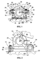
- a support arrangement 10 of a roll of a fibrous-web machine according to an advantageous embodiment of the invention shown in connection with Fig. 1 comprises a first frame part 12 and a second frame part 22.
- the first frame part 12 consists of a bearing housing 14 and fastening lugs 16 in connection with it.
- the fastening lugs 16 are arranged on the opposite sides of the bearing housing 14 extending from the bearing housing 14 substantially at opposite directions in a parallel plane with the longitudinal axis of the roll which is in Fig. 1 perpendicular in relation to the figure.
- Fig. 1 figuratively shows with a dashed line also a bearing arrangement 18 arranged into connection with the bearing housing 14 and a roll 20 which is rotatably supported in the bearing housing through the bearing arrangement 18.
- the bearing housing 14 supports itself in this embodiment to the second frame part 22 and through a third frame part 24 substantially rigidly in a frame or foundation 26 of the fibrous-web machine.
- the first frame part 12 is fastened to the second frame part 22 by means of an elastic fastening.
- an elastic fastening Through the fastening lugs 16 of the first frame part 12 is arranged a drawbar, bolt or equivalent 28, one or more.
- the bolt 28 extends through the fastening lug 16 and is fastened on the inner thread of an opening of the second frame part 23.
- elastic pieces 32 Between a plate 29 between the fastening lug 16 and the head of the bolt 28 and the fastening lug 16 and the second frame part 22 are arranged elastic pieces 32 which enable elastic fastening.
- the bolts 28 are tightened against separate sleeves 30.
- the sleeves 30 extend from the plate 29 of the bolt 28 to the surface of the second frame part 22, whereby the length of the sleeve 30 here determines the compression of the elastic pieces 32.
- a motion direction control arrangement 34 in the embodiment of Fig. 1 .
- the motion direction control arrangement 34 comprises in the embodiment of Fig. 1 firstly thin support parts 36 connected to the support arranged through the fastening lugs 16.
- the support parts 36 are planar pieces which are advantageously manufactured of spring steel or equivalent.
- three separate support parts of the thickness of 1 mm used in a test arrangement can be mentioned in which as the length of a deformation zone 38 was successfully used the length of 30-60 mm. Based on experiences, the deformation zone is at least 20 mm depending on the application.
- the total thickness of the support part is in practice at the most 15% of the length of its deformation zone 38, whereby it is thus thin.
- the deformation zone is the zone for the part of which the support part 36 is free to deflect in use.
- the support part 36 is fastened by bolts or equivalent from the vicinity of its second edge to the second frame part 22 and, correspondingly, from the vicinity of the first edge to the first frame part 12, here between the elastic piece 32 and the fastening lug 16.
- the support part 36 then limits the direction of elasticity.
- the elastic fastening implemented by means of the bolts 28, the sleeves 30 and the elastic pieces 32 allows the elastic motion of the first frame part 12 mainly in the direction of the sleeve and the bolt and not substantially in other directions.
- the bearing housing 14 comprises a shoulder 42 against which the support part 36 is arranged from its first edge.
- the support part 36 allows the motion between the first and the second frame part 12; 22 substantially approximately in the perpendicular direction in relation to the plane of the support part.
- the motion of the first and the second frame part in the direction of the plane of the support part is mainly possible only within the elongation of the support part which is very minimal in practice.
- a third support part 36 which extends to the second frame part 22 from its both ends and is fastened by its middle part with bolts on the lower surface of the first frame part 12 i.e. here the bearing housing.
- the deformation length 38 is chosen slightly longer than that of the support parts in connection with the fastening lugs 16.
- Different support parts 36 can be provided with different characteristics, such as manufactured of different material in a way required by the application.
- the bearing housing i.e. the first frame part 12 and the second frame part 22 comprise control surfaces 40 substantially parallel to each other.
- the direction of the control surfaces joins the direction of the allowed motion and is substantially perpendicular in relation to the direction of the plane of the support part 36.
- the basic arrangement is such that it operationally includes three parts: the first frame part 12 inside of which there is an actual roller bearing of the roll, the second frame part 22 which is fastened as rigidly as possible to the frame or foundation of the fibrous-web machine, and the elastic and damping support arrangement enabling the motion between these 12; 22.
- the bearing housing is manufactured such that an as large as possible part of motion taking place due to dynamic load in the housing will occur in a part which damps vibration well.
- the support of the rolls of fibrous-web machines e.g. a carrier roll of a slitter-winder
- the support of the rolls of fibrous-web machines has to be statically at least so rigid in all directions that the lowest natural frequencies of the roll are somewhat higher than the greatest rotational frequency of the roll.
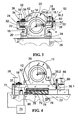
- Fig. 2 shows another embodiment of a support arrangement 10 of a roll according to the invention.
- the first frame part 12 comprises two main parts which are a fastening part 12.1 of the end of the roll and a fastening bar 12.2.
- the fastening part of the end of the roll 20 can be constructed such that it enables the fastening of the roll end stationarily, whereby the roll being used can be e.g. a deflection-compensated roll.
- the first frame part 12 can be constructed to comprise a bearing housing, whereby the rotatable shaft of the roll end is fastened in the bearing.
- the first frame part 12 is fastened to the second frame part 22 by means of an elastic fastening.
- the elastic fastening has been implemented such that the first end of the first frame part 12 is fastened by the bolt joint 28 to the second frame part 22 such that the fastening lug 16 of the first frame part is tightened by one or more bolts 28 between the elastic pieces 32.
- the motion direction control arrangement 34 comprises a pivot 50 arranged in the second fastening lug.
- the pivot comprises a pin or equivalent 52 fastened in the fastening lug by its ends and a bearing or sleeve 54 arranged in the fastening lug.
- machine direction MD cross direction CD
- vertical direction Z whereby the cross direction in the figure is perpendicular in relation to the plane of the figure.
- rotational motion around the longitudinal axis of the pin 52 is possible for the first frame part 12. Clearances between the pin 52 and the sleeve 54 are chosen in practice small enough, whereby the machine-directional MD and vertical Z motion is practically prevented.
- the rotational motion is so little that the motion conveyed by the first frame part 12 for the elastic pieces 32 of its second end is almost linear. Due to the effect of the pivot 50, the first frame part 12 can thus move in relation to the second frame part 22 substantially only in one direction.
- Fig. 2 shows as an example a situation in which the roll 20 supports a paper reel 56. Then, the position of the pivot 50 is chosen such that a straight line L1 drawn via the nip of the reel 56 and the centre of the roll can be arranged perpendicular in relation to a straight line L2 passing the centres of the pivot and the roll.
- Fig. 3 shows a third embodiment of the invention.
- the support arrangement 10 of the roll of the fibrous-web machine comprises the first frame part 12 and the second frame part 22.
- the first frame part consists here of the bearing housing 14 and the fastening lugs 16 in connection with it.
- the fastening lugs are arranged on the opposite sides of the bearing housing 14 extending from the bearing housing at opposite directions in a parallel plane with the longitudinal axis of the roll which longitudinal axis is in Fig. 3 perpendicular in relation to the figure.
- Fig. 3 figuratively shows with a dashed line also the bearing arrangement 18 arranged in the bearing housing and the roll 20 which is rotatably supported in the bearing housing through the bearing arrangement 18.
- the bearing housing supports itself in this embodiment to the second frame part 22 and through the third frame part 24 to the frame or foundation 26 of the fibrous-web machine.
- the first fastening lug 16 of the bearing housing which is in Fig. 3 on the left side, is provided with the elastic fastening of the fastening lug 16 shown in Fig. 1 .
- the fastening lug has been fastened with the bolt joint 28 to the second frame part 22 supported between the elastic pieces 32.
- the motion direction control arrangement 34 on the left comprises firstly the thin support part 36 connected to the support arranged through the fastening lugs 16.
- the support part 36 is thus a planar thin piece which is advantageously manufactured of spring steel or equivalent.
- the support part 36 is fastened by bolts or equivalent from the vicinity of its second edge to the second frame part 22 and, correspondingly, from the vicinity of the first edge to the first frame part 12, here between the elastic piece 32 and the fastening lug 16.
- the support part 36 limits the direction of elasticity.
- the bearing housing 14 comprises the shoulder 42 against which the support part is arranged from its first edge. This prevents the motion between the support part 36 and the first frame part 12 and thus limits the motion of the first frame part and the roll in the direction of the plane which here corresponds the plane of the machine direction MD and the cross direction CD.
- the support part 36 is stationarily fastened from its ends to the first and the second frame part and because its width is relatively large, it also prevents the cross-directional CD motion in addition to the machine direction motion.
- the direction of the plane of the support part 36 thus determines the directions in which the support part particularly limits the motion. Because the fastening points of the first and the second edge of the support part 36 to the first and the second frame part 12; 22 are at a distance from each other, deformation in the support part 36 can occur such that it deflects like a leaf spring. Then, the support part 36 allows the motion between the first and the second frame part substantially approximately in the perpendicular direction in relation to the plane of the support part.
- the second fastening lug (on the right in the figure) is pivoted in a special way to the second frame part 22.
- the pivoting 50 of Fig. 3 corresponds the pivot 50 shown in Fig. 2 , but its structure is different.
- the pivoting of Fig. 3 is totally clearance-free, whereby it is particularly well suitable for supporting the carrier roll of the winding section of the slitter-winder and for other such targets in which the accurate positioning of the roll is particularly important.
- the pivoting according to the invention shown in Fig. 3 will be described in the following with reference to Figs. 3 and 6 .
- the pivoting is based on two or more thin support parts 36 arranged on planes intersecting each other.
- a pivot shaft X of the pivot formed thus is on the intersection line of the planes.
- the support parts 36 forming the pivot comprise a first fastening zone 60 extending in the cross-direction of the support part over which zone are arranged holes 62 for the fastening at a distance from each other.
- On the fastening zone there are arranged several binder parts 64 extending in the longitudinal direction of the support part also at a distance from each other.
- the distance between the binder parts 64 is chosen such that from each gap it is possible to bring through a binder part of other support parts 36 used in the pivoting.
- the direction of the binder parts determines the direction of each support part in which its elasticity is particularly minimal.
- the deformation zone 38 of the pivoting according to the invention is arranged.
- each binder part in the embodiment of Fig. 6 there is a hole 66 by means of which each binder part and thus support part in its whole can be fastened from its other end.
- the binder part 64 is thin in the direction of the normal of the deformation zone, whereby it is able to deflect relatively easy, but wide on the plane of the deformation zone, whereby the support part and the pivot formed thus of the support parts is substantially rigid apart from the pivot function.
- the support part can be formed of one plate 68 or a stack formed by several single plates 68.1, 68.2, 68.N on top of each other. Both ways are usable as such, but the stack of plates enables the greater deflection of the pivot i.e. it is possible to arrange the rotational angle larger by using the stack of plates.
- a support part 36.1 on the first plane is rigidly fastened from its first end i.e. from its fastening zone 60 with bolts to the second frame part 22.
- the binder parts 64 of the support part extend between the fastening lug 16 and the fastening piece 16.1 in which the bolts arranged through the hole 66 of the binder part tighten the other end of the support piece.
- a support part 36.2 on the second plane is correspondingly fastened from its first end to the second frame part and from its second end to the fastening piece 16.
- the planes are perpendicular against each other. Then, a pivot is formed which allows rotation on the intersection line X of the plane, but is substantially rigid in other directions.
- the rigidity of the pivoting can be affected, among others.
- Fig. 4 the operation of the pivot between the first frame part 12 and the second frame part 22 corresponds the one shown in Fig. 3 .
- two support parts arranged on planes intersecting each other, the deformation zone of which is utilised in providing the pivoting, based on the principle shown in Figs. 3 and 6 .
- the first fastening lug 16 of the first frame part 12 is also here tightened with the bolt 28 between elastic pieces 32 and 32'.
- the elastic piece 32 above the fastening lug is arranged here into connection with the bolt, but the elastic piece 32' below is on the lower surface of the first frame part 12 so that the bolt does not go through it.
- the distance adjustment apparatus By the distance adjustment apparatus, the position between the first 12 and the second frame part 22 can be adjusted in relation to each other.
- Such a requirement can be in some targets of application process-technical adjustment, such as that of nip force, but principally its purpose is to compensate the permanent deformations of the elastic pieces which can occur during use as time passes.
- the arrangement also comprises a distance or position sensor 72 based on the measuring data of which the distance adjustment apparatus is adjusted and the position of the first 12 and the second frame part 22 in relation to each other is set.
- the arrangement can also comprise a control unit 74 which receives the measuring data of the distance or position sensor 72 and processes it e.g. by sending a measurement value to be viewed on the control apparatus, by alarming of a distance going outside set values or by directly controlling the distance adjustment apparatus 70 by a correcting measure.
- the distance adjustment apparatus 70 comprises in this embodiment two pieces 76 on top of each other the corresponding surfaces of which are inclined in different directions forming a wedge-shaped gap.
- a wedge piece 78 is arranged into this gap.
- a screw device 80 which, when being tightened, is arranged to provide pull in the wedge piece causing counter force in the pieces 76 being on top of each other on its opposite sides. This provides the motion of the wedge piece in the gap in relation to the pieces 76 and, from the effect of their shapes, the motion of the pieces 76 farther from each other and further the motion of the first frame part farther from the second frame part.
- the arrangement also operates in a corresponding way in the other direction.
- Fig. 5 shows an embodiment of the pivoting 50 according to the invention.
- the pivoting between the first frame part 12 and the second frame part 22 is provided by using three support parts 36 intersecting each other on the same plane.
- the pivot shaft is on the intersection line X of the planes.
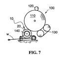
- Fig. 7 shows a support arrangement 10 of a roll according to the invention applied in a winding section 100 of a slitter-winder of a fibrous web.
- the winding section is a carrier-roll winder in which the roll 20 is arranged as a front roll 140.
- the fibrous web w is guided through the roll 20 into a web reel 110 which is supported also by a set of belt rolls 130 and a press roll 120.
- the support of the press roll 120 can comprise a support arrangement according to the invention.
- the present invention relates to a support arrangement (10) of a roll of a fibrous-web machine, which comprises a first frame part (12) in which the roll (20) of the fibrous-web machine is supportable from its end when in use and a second frame part (22) in which the first frame part (12) is fastened by means of an elastic fastening.
- the arrangement comprises a motion direction control arrangement (34) for controlling the direction of the motion allowed by the elastic fastening in a way determined by the direction control arrangement (34).
Landscapes
- Engineering & Computer Science (AREA)
- General Engineering & Computer Science (AREA)
- Mechanical Engineering (AREA)
- Paper (AREA)
- Winding Of Webs (AREA)
- Replacement Of Web Rolls (AREA)
- Preliminary Treatment Of Fibers (AREA)
Abstract
Description
- The present invention relates to a support arrangement of a roll in a fibrous-web machine according to the preamble of claim 1, which arrangement comprises a first frame part in which the roll of the fibrous-web machine is supportable from its end and a second frame part in which the first frame part is fastened by means of an elastic fastening.
- The invention generally relates to supporting a bearing of a roll of a fibrous-web machine or an equivalent shaft to the frame structure. Particularly, the invention relates to a roll of a device or a section of a paper or board machine and supporting its bearing to the frame structure when external force applies to the roll. Such external force can be caused e.g. by another roll, a support fabric or a web reel.
- The vibration of rolls is a great problem with present-day fibrous-web machines, inter alia, due to the increase in operating speed. Traditionally, the rolls are fastened in the foundation as rigidly as possible, this is particularly the case with the carrier rolls of a slitter-winder.
- Specifications
WO9849394 WO0004227 WO0004228 -
FI patent 94458 - Specification
JP 3082843 - The object of the invention is to provide a support arrangement of a roll of a fibrous-web machine according to the preamble of claim 1, which arrangement comprises a first frame part in which the roll is supportable from its end and a second frame part in which the first frame part is fastened by means of an elastic fastening, which support arrangement with allowed elasticity has at least one certain determined direction and which is substantially statically rigid in other directions.
- This object is achieved according to the invention such that the support arrangement comprises a motion direction control arrangement for controlling the direction of the motion allowed by the elastic fastening in a way determined by the direction control arrangement.
- With this arrangement, such an effect is achieved that in the support the dampening of vibration is provided effective without endangering the rigidity of the support in such directions which require rigidity.
- A direction control arrangement of a support arrangement of a roll according to an embodiment of the invention comprises at least one support part which is fastened in both the first frame part and the second frame part. The support part is arranged according to the invention substantially perpendicular in relation to the direction allowed by elasticity and it is thin in the direction allowed by elasticity. A support part arranged this way prevents the mutual motion of the first piece and the second piece mainly in other than the substantially perpendicular direction in relation to the plane of the support part.
- Advantageously, the thin support part is a piece having a long deformation zone. The thickness of the support part is typically at the most 10% of the length of its deformation zone.
- In a support arrangement of a roll according to an embodiment of the invention, the direction control arrangement comprises a pivot arranged in a second fastening lug comprised by the first frame part which lug substantially allows only rotational motion. By means of the pivot, motion is prevented in non-desired directions and allowed in a desired direction.
- The pivot comprises according to an embodiment at least two support parts being on planes intersecting on a joint intersection line.
- According to an embodiment of the invention, the support parts comprise binder parts extending in the longitudinal direction of the support part at a distance from each other such that from each gap determined by the distance a binder part of another support part / other support parts used in pivoting can be brought through.
- The elastic fastening comprises an elastic piece arranged between the first and the second frame part.
- Other additional features characteristic of the invention are illustrated in the accompanying claims.
- In this context, a paper machine means different fibrous web manufacturing or processing apparatuses or their sections, such as paper machines, board machines, press sections, reelers, calenders and slitter-winders. The invention is well applicable, inter alia, in connection with the carrier rolls and/or press rolls of the winding section of slitter-winders.
- Other characteristic features of the method and apparatus according to the invention are illustrated in the accompanying claims.
- The invention and its operation will now be described with reference to the accompanying schematic figures in which
-
Fig. 1 shows a support arrangement of a roll according to an advantageous embodiment of the invention, -
Fig. 2 shows a second support arrangement of a roll according to an advantageous embodiment of the invention, -
Fig. 3 shows a third support arrangement of a roll according to an advantageous embodiment of the invention, -
Fig. 4 shows a fourth support arrangement of a roll according to an advantageous embodiment of the invention, -
Fig. 5 shows an embodiment of pivoting according to the invention, -
Fig. 6 shows an embodiment of binder pieces according to the invention, and -
Fig. 7 shows a support arrangement of a roll according to the invention applied in the winding section of a slitter-winder. - The rolls of the fibrous-web machine are typically supported from their ends in the frame or foundation of the machine. The structure of the roll can be such that it comprises a hollow shell and heads arranged to its ends in which head there further is a quite short shaft. Such a roll is rotatably supported by the above-mentioned shafts in the frame or foundation of the machine. The structure of the roll can also be such that it comprises a frame stationary when operated supportable to the frame from its ends and a shell rotatably arranged around it. In such a roll, the shell can even be to some extent elastic, and a shoe has been arranged inside it to support the shell, whereby the roll is often called a long-nip roll.
- A
support arrangement 10 of a roll of a fibrous-web machine according to an advantageous embodiment of the invention shown in connection withFig. 1 comprises afirst frame part 12 and asecond frame part 22. Here, thefirst frame part 12 consists of a bearinghousing 14 and fasteninglugs 16 in connection with it. The fasteninglugs 16 are arranged on the opposite sides of the bearinghousing 14 extending from thebearing housing 14 substantially at opposite directions in a parallel plane with the longitudinal axis of the roll which is inFig. 1 perpendicular in relation to the figure.Fig. 1 figuratively shows with a dashed line also abearing arrangement 18 arranged into connection with the bearinghousing 14 and aroll 20 which is rotatably supported in the bearing housing through the bearingarrangement 18. The bearinghousing 14 supports itself in this embodiment to thesecond frame part 22 and through athird frame part 24 substantially rigidly in a frame orfoundation 26 of the fibrous-web machine. - The
first frame part 12 is fastened to thesecond frame part 22 by means of an elastic fastening. In this embodiment, it has been implemented in the following way. Through the fastening lugs 16 of thefirst frame part 12 is arranged a drawbar, bolt or equivalent 28, one or more. Thebolt 28 extends through thefastening lug 16 and is fastened on the inner thread of an opening of the second frame part 23. Between aplate 29 between thefastening lug 16 and the head of thebolt 28 and thefastening lug 16 and thesecond frame part 22 are arrangedelastic pieces 32 which enable elastic fastening. Thebolts 28 are tightened againstseparate sleeves 30. Thesleeves 30 extend from theplate 29 of thebolt 28 to the surface of thesecond frame part 22, whereby the length of thesleeve 30 here determines the compression of theelastic pieces 32. In order to be able to control the direction of the motion enabled by elasticity, there is a motiondirection control arrangement 34 in the embodiment ofFig. 1 . - To facilitate understanding the invention, it is possible in a practical situation to determine the so-called machine direction MD, cross direction CD and vertical direction Z, whereby the cross direction in the figure is perpendicular in relation to the plane of the figure. In the following description, these will also be used as assistance in indicating directions.
- The motion
direction control arrangement 34 comprises in the embodiment ofFig. 1 firstlythin support parts 36 connected to the support arranged through the fastening lugs 16. Thesupport parts 36 are planar pieces which are advantageously manufactured of spring steel or equivalent. As an example of the size of the fastening lugs 16, three separate support parts of the thickness of 1 mm used in a test arrangement can be mentioned in which as the length of adeformation zone 38 was successfully used the length of 30-60 mm. Based on experiences, the deformation zone is at least 20 mm depending on the application. The total thickness of the support part is in practice at the most 15% of the length of itsdeformation zone 38, whereby it is thus thin. The deformation zone is the zone for the part of which thesupport part 36 is free to deflect in use. Thesupport part 36 is fastened by bolts or equivalent from the vicinity of its second edge to thesecond frame part 22 and, correspondingly, from the vicinity of the first edge to thefirst frame part 12, here between theelastic piece 32 and thefastening lug 16. Thesupport part 36 then limits the direction of elasticity. The elastic fastening implemented by means of thebolts 28, thesleeves 30 and theelastic pieces 32 allows the elastic motion of thefirst frame part 12 mainly in the direction of the sleeve and the bolt and not substantially in other directions. For ensuring the prevention of the motion of thefirst frame part 12 and theroll 20 in the above-mentioned other directions, the bearinghousing 14 comprises ashoulder 42 against which thesupport part 36 is arranged from its first edge. This prevents the motion between thesupport part 36 and thefirst frame part 12 and thus limits the motion of thefirst frame part 12 and theroll 20 in the direction of the plane of thesupport part 36 which here corresponds the plane determined by the machine direction MD and the cross direction CD. Because thesupport part 36 is stationarily fastened from its ends to the first and thesecond frame part 12; 22 and because its width is relatively large, it also prevents the cross-directional CD motion. The direction of the plane of thesupport part 36 thus determines the directions in which thesupport part 36 particularly limits the motion. Because the fastening points of the first and the second edge of the support part to the first and the second frame part are at a distance from each other, deformation in thesupport part 36 can occur such that it deflects like a leaf spring.
Then, thesupport part 36 allows the motion between the first and thesecond frame part 12; 22 substantially approximately in the perpendicular direction in relation to the plane of the support part. On the other hand, the motion of the first and the second frame part in the direction of the plane of the support part is mainly possible only within the elongation of the support part which is very minimal in practice. - In the embodiment of
Fig. 1 , below the bearinghousing 14 there is athird support part 36 which extends to thesecond frame part 22 from its both ends and is fastened by its middle part with bolts on the lower surface of thefirst frame part 12 i.e. here the bearing housing. In this support part, thedeformation length 38 is chosen slightly longer than that of the support parts in connection with the fastening lugs 16.Different support parts 36 can be provided with different characteristics, such as manufactured of different material in a way required by the application. - For minimising the motion in the direction of the plane of the
support part 36, the bearing housing i.e. thefirst frame part 12 and thesecond frame part 22 comprisecontrol surfaces 40 substantially parallel to each other. The direction of the control surfaces joins the direction of the allowed motion and is substantially perpendicular in relation to the direction of the plane of thesupport part 36. - In this embodiment of
Fig. 1 , the basic arrangement is such that it operationally includes three parts: thefirst frame part 12 inside of which there is an actual roller bearing of the roll, thesecond frame part 22 which is fastened as rigidly as possible to the frame or foundation of the fibrous-web machine, and the elastic and damping support arrangement enabling the motion between these 12; 22. - Particularly in the carrier-roll applications of the winding sections of the slitter-winder, it is essential that clearances are minimised and the elastic motion takes place within the limits allowed by the elastic pieces. For maximising the damping capacity of the bearing housing, the bearing housing is manufactured such that an as large as possible part of motion taking place due to dynamic load in the housing will occur in a part which damps vibration well.
- It is thus essential to construct the support such that it is as much as possible supported by the damping part and the direction control arrangement in the direction of the motion of the vibration, sufficiently rigid in other directions and substantially clearance-free in all directions.
- Typically, the support of the rolls of fibrous-web machines, e.g. a carrier roll of a slitter-winder, has to be statically at least so rigid in all directions that the lowest natural frequencies of the roll are somewhat higher than the greatest rotational frequency of the roll.
-
Fig. 2 shows another embodiment of asupport arrangement 10 of a roll according to the invention. Here, thefirst frame part 12 comprises two main parts which are a fastening part 12.1 of the end of the roll and a fastening bar 12.2. The fastening part of the end of theroll 20 can be constructed such that it enables the fastening of the roll end stationarily, whereby the roll being used can be e.g. a deflection-compensated roll. It is evident that thefirst frame part 12 can be constructed to comprise a bearing housing, whereby the rotatable shaft of the roll end is fastened in the bearing. - The
first frame part 12 is fastened to thesecond frame part 22 by means of an elastic fastening. In this embodiment, the elastic fastening has been implemented such that the first end of thefirst frame part 12 is fastened by the bolt joint 28 to thesecond frame part 22 such that thefastening lug 16 of the first frame part is tightened by one ormore bolts 28 between theelastic pieces 32. - In the embodiment of
Fig. 2 , the motiondirection control arrangement 34 comprises apivot 50 arranged in the second fastening lug. The pivot comprises a pin or equivalent 52 fastened in the fastening lug by its ends and a bearing orsleeve 54 arranged in the fastening lug. Also in this context, it is possible to determine the so-called machine direction MD, cross direction CD and vertical direction Z, whereby the cross direction in the figure is perpendicular in relation to the plane of the figure. Then, rotational motion around the longitudinal axis of thepin 52 is possible for thefirst frame part 12. Clearances between thepin 52 and thesleeve 54 are chosen in practice small enough, whereby the machine-directional MD and vertical Z motion is practically prevented. In practice, the rotational motion is so little that the motion conveyed by thefirst frame part 12 for theelastic pieces 32 of its second end is almost linear. Due to the effect of thepivot 50, thefirst frame part 12 can thus move in relation to thesecond frame part 22 substantially only in one direction. - In practice, the direction in which motion is allowed is chosen case-specifically. It can be e.g. precisely the vertical direction.
Fig. 2 shows as an example a situation in which theroll 20 supports apaper reel 56. Then, the position of thepivot 50 is chosen such that a straight line L1 drawn via the nip of thereel 56 and the centre of the roll can be arranged perpendicular in relation to a straight line L2 passing the centres of the pivot and the roll. -
Fig. 3 shows a third embodiment of the invention. Here, thesupport arrangement 10 of the roll of the fibrous-web machine comprises thefirst frame part 12 and thesecond frame part 22. The first frame part consists here of the bearinghousing 14 and the fastening lugs 16 in connection with it. The fastening lugs are arranged on the opposite sides of the bearinghousing 14 extending from the bearing housing at opposite directions in a parallel plane with the longitudinal axis of the roll which longitudinal axis is inFig. 3 perpendicular in relation to the figure.Fig. 3 figuratively shows with a dashed line also the bearingarrangement 18 arranged in the bearing housing and theroll 20 which is rotatably supported in the bearing housing through the bearingarrangement 18. The bearing housing supports itself in this embodiment to thesecond frame part 22 and through thethird frame part 24 to the frame orfoundation 26 of the fibrous-web machine. - The
first fastening lug 16 of the bearing housing, which is inFig. 3 on the left side, is provided with the elastic fastening of thefastening lug 16 shown inFig. 1 . There, the fastening lug has been fastened with the bolt joint 28 to thesecond frame part 22 supported between theelastic pieces 32. InFig. 3 , the motiondirection control arrangement 34 on the left comprises firstly thethin support part 36 connected to the support arranged through the fastening lugs 16. Thesupport part 36 is thus a planar thin piece which is advantageously manufactured of spring steel or equivalent. Thesupport part 36 is fastened by bolts or equivalent from the vicinity of its second edge to thesecond frame part 22 and, correspondingly, from the vicinity of the first edge to thefirst frame part 12, here between theelastic piece 32 and thefastening lug 16. Thesupport part 36 limits the direction of elasticity. For ensuring the positioning of thesupport part 36, the bearinghousing 14 comprises theshoulder 42 against which the support part is arranged from its first edge. This prevents the motion between thesupport part 36 and thefirst frame part 12 and thus limits the motion of the first frame part and the roll in the direction of the plane which here corresponds the plane of the machine direction MD and the cross direction CD. Because thesupport part 36 is stationarily fastened from its ends to the first and the second frame part and because its width is relatively large, it also prevents the cross-directional CD motion in addition to the machine direction motion. The direction of the plane of thesupport part 36 thus determines the directions in which the support part particularly limits the motion. Because the fastening points of the first and the second edge of thesupport part 36 to the first and thesecond frame part 12; 22 are at a distance from each other, deformation in thesupport part 36 can occur such that it deflects like a leaf spring. Then, thesupport part 36 allows the motion between the first and the second frame part substantially approximately in the perpendicular direction in relation to the plane of the support part. - In the embodiment of
Fig. 3 , the second fastening lug (on the right in the figure) is pivoted in a special way to thesecond frame part 22. Operationally from the viewpoint of the invention, the pivoting 50 ofFig. 3 corresponds thepivot 50 shown inFig. 2 , but its structure is different. The pivoting ofFig. 3 is totally clearance-free, whereby it is particularly well suitable for supporting the carrier roll of the winding section of the slitter-winder and for other such targets in which the accurate positioning of the roll is particularly important. - The pivoting according to the invention shown in
Fig. 3 will be described in the following with reference toFigs. 3 and6 . The pivoting is based on two or morethin support parts 36 arranged on planes intersecting each other. A pivot shaft X of the pivot formed thus is on the intersection line of the planes. Thesupport parts 36 forming the pivot comprise afirst fastening zone 60 extending in the cross-direction of the support part over which zone are arrangedholes 62 for the fastening at a distance from each other. On the fastening zone, there are arrangedseveral binder parts 64 extending in the longitudinal direction of the support part also at a distance from each other. The distance between thebinder parts 64 is chosen such that from each gap it is possible to bring through a binder part ofother support parts 36 used in the pivoting. The direction of the binder parts determines the direction of each support part in which its elasticity is particularly minimal. In the binder parts, thedeformation zone 38 of the pivoting according to the invention is arranged. - At the end of each binder part in the embodiment of
Fig. 6 , there is ahole 66 by means of which each binder part and thus support part in its whole can be fastened from its other end. Thebinder part 64 is thin in the direction of the normal of the deformation zone, whereby it is able to deflect relatively easy, but wide on the plane of the deformation zone, whereby the support part and the pivot formed thus of the support parts is substantially rigid apart from the pivot function. - The support part can be formed of one
plate 68 or a stack formed by several single plates 68.1, 68.2, 68.N on top of each other. Both ways are usable as such, but the stack of plates enables the greater deflection of the pivot i.e. it is possible to arrange the rotational angle larger by using the stack of plates. - In the
pivot 50 shown inFig. 3 , a support part 36.1 on the first plane is rigidly fastened from its first end i.e. from itsfastening zone 60 with bolts to thesecond frame part 22. Thebinder parts 64 of the support part extend between thefastening lug 16 and the fastening piece 16.1 in which the bolts arranged through thehole 66 of the binder part tighten the other end of the support piece. A support part 36.2 on the second plane is correspondingly fastened from its first end to the second frame part and from its second end to thefastening piece 16. Here, the planes are perpendicular against each other. Then, a pivot is formed which allows rotation on the intersection line X of the plane, but is substantially rigid in other directions. - By the length of the deformation zone, i.e. the zone for the part of which the support part, or in more detail its binder part, is free to deflect in the installation, the rigidity of the pivoting can be affected, among others.
- In
Fig. 4 , the operation of the pivot between thefirst frame part 12 and thesecond frame part 22 corresponds the one shown inFig. 3 . Here are arranged two support parts arranged on planes intersecting each other, the deformation zone of which is utilised in providing the pivoting, based on the principle shown inFigs. 3 and6 . - The
first fastening lug 16 of thefirst frame part 12 is also here tightened with thebolt 28 betweenelastic pieces 32 and 32'. Theelastic piece 32 above the fastening lug is arranged here into connection with the bolt, but the elastic piece 32' below is on the lower surface of thefirst frame part 12 so that the bolt does not go through it. Between the elastic piece 32' below and the second frame part 22 (the order can also be reversed), there is adistance adjustment apparatus 70. By the distance adjustment apparatus, the position between the first 12 and thesecond frame part 22 can be adjusted in relation to each other. Such a requirement can be in some targets of application process-technical adjustment, such as that of nip force, but principally its purpose is to compensate the permanent deformations of the elastic pieces which can occur during use as time passes. The arrangement also comprises a distance orposition sensor 72 based on the measuring data of which the distance adjustment apparatus is adjusted and the position of the first 12 and thesecond frame part 22 in relation to each other is set. The arrangement can also comprise acontrol unit 74 which receives the measuring data of the distance orposition sensor 72 and processes it e.g. by sending a measurement value to be viewed on the control apparatus, by alarming of a distance going outside set values or by directly controlling thedistance adjustment apparatus 70 by a correcting measure. - The
distance adjustment apparatus 70 comprises in this embodiment twopieces 76 on top of each other the corresponding surfaces of which are inclined in different directions forming a wedge-shaped gap. Into this gap, awedge piece 78 is arranged. At the narrower end of the wedge piece, there is ascrew device 80 which, when being tightened, is arranged to provide pull in the wedge piece causing counter force in thepieces 76 being on top of each other on its opposite sides. This provides the motion of the wedge piece in the gap in relation to thepieces 76 and, from the effect of their shapes, the motion of thepieces 76 farther from each other and further the motion of the first frame part farther from the second frame part. The arrangement also operates in a corresponding way in the other direction. -
Fig. 5 shows an embodiment of the pivoting 50 according to the invention. In this embodiment, the pivoting between thefirst frame part 12 and thesecond frame part 22 is provided by using threesupport parts 36 intersecting each other on the same plane. Also here, the pivot shaft is on the intersection line X of the planes. -
Fig. 7 shows asupport arrangement 10 of a roll according to the invention applied in a windingsection 100 of a slitter-winder of a fibrous web. Here, the winding section is a carrier-roll winder in which theroll 20 is arranged as a front roll 140. In the winder, the fibrous web w is guided through theroll 20 into aweb reel 110 which is supported also by a set of belt rolls 130 and apress roll 120. Also the support of thepress roll 120 can comprise a support arrangement according to the invention. - It should be noticed that only a few of the most advantageous embodiments of the invention were described above. Thus, it is evident that the invention is not limited to the above-mentioned embodiments, but it can be applied in many ways within the scope defined by the enclosed claims. Also, characteristics described in connection with different embodiments can be used in other embodiments if technical possibilities exist.
The present invention relates to a support arrangement (10) of a roll of a fibrous-web machine, which comprises a first frame part (12) in which the roll (20) of the fibrous-web machine is supportable from its end when in use and a second frame part (22) in which the first frame part (12) is fastened by means of an elastic fastening. The arrangement comprises a motion direction control arrangement (34) for controlling the direction of the motion allowed by the elastic fastening in a way determined by the direction control arrangement (34).
Claims (12)
- A support arrangement (10) of a roll of a fibrous-web machine, which comprises a first frame part (12) in which a roll (20) is supportable from its end, and a second frame part (22) in which the first frame part (12) is fastened by means of an elastic fastening, characterised in that the arrangement comprises a motion direction control arrangement (34) for controlling the motion allowed by the elastic fastening in a way determined by the direction control arrangement (34).
- A support arrangement of a roll according to claim 1, characterised in that the direction control arrangement (34) comprises at least one support part (36) which is fastened both in the first frame part (12) and the second frame part (22), and that the support part (36) is arranged substantially perpendicular in relation to the allowed direction of the elasticity, and that the support part (36) is thin in the allowed direction of elasticity.
- A support arrangement of a roll according to claim 2, characterised in that the thin support part (36) is a piece having a long deformation zone.
- A support arrangement of a roll according to claim 1, characterised in that the first frame part (12) comprises a fastening part (12.1) of the roll end and a first fastening lug (16) and that the direction control arrangement (34) is arranged into connection with the first fastening lug (16).
- A support arrangement of a roll according to claim 4, characterised in that the first frame part (12) further comprises a second fastening lug (16) and that the direction control arrangement comprises a pivot (50) arranged in the second fastening lug (16) which substantially allows only rotational motion.
- A support arrangement of a roll according to claim 5, characterised in that the pivot (50) comprises a pin (52) and a bearing (54) arranged within each other.
- A support arrangement of a roll according to claim 5, characterised in that the pivot (50) comprises at least two support parts (36) being on planes intersecting each other on a joint intersection line.
- A support arrangement of a roll according to claim 7, characterised in that the support parts (36) comprise binder parts (64) at a distance from each other such that from each gap determined by the distance it is possible to bring through a binder part of other support parts used in the pivoting.
- A support arrangement of a roll according to claim 2, characterised in that the first frame part (12) comprises a bearing housing (14) and the first fastening lug (16) and the second fastening lug (16) extending substantially in opposite directions from it and that both the first and the second fastening lug are provided with the direction control arrangement (34).
- A support arrangement of a roll according to any one of the preceding claims, characterised in that the elastic fastening comprises at least one elastic piece (32) arranged between the first (12) and the second frame part (22).
- A support arrangement of a roll according to any one of preceding claims, characterised in that the support arrangement of the roll is arranged into connection with a roll (140) of a winding section (100) of a slitter-winder of a fibrous-web machine.
- A support arrangement of a roll according to claim 11, characterised in that the roll is a carrier or a press roll (140, 120).
Applications Claiming Priority (1)
| Application Number | Priority Date | Filing Date | Title |
|---|---|---|---|
| FI20075476A FI123753B (en) | 2007-06-21 | 2007-06-21 | Arrangements for supporting a roller in a fiber web machine |
Publications (3)
| Publication Number | Publication Date |
|---|---|
| EP2006227A2 true EP2006227A2 (en) | 2008-12-24 |
| EP2006227A3 EP2006227A3 (en) | 2009-11-04 |
| EP2006227B1 EP2006227B1 (en) | 2012-04-11 |
Family
ID=38212447
Family Applications (1)
| Application Number | Title | Priority Date | Filing Date |
|---|---|---|---|
| EP08157574A Active EP2006227B1 (en) | 2007-06-21 | 2008-06-04 | Support arrangement of roll in fibrous-web machine |
Country Status (5)
| Country | Link |
|---|---|
| US (1) | US8146397B2 (en) |
| EP (1) | EP2006227B1 (en) |
| AT (1) | ATE553050T1 (en) |
| CA (1) | CA2635512C (en) |
| FI (1) | FI123753B (en) |
Cited By (3)
| Publication number | Priority date | Publication date | Assignee | Title |
|---|---|---|---|---|
| WO2012056112A1 (en) * | 2010-10-28 | 2012-05-03 | Metso Paper, Inc. | Roll support arrangement of a fiber web machine and a partial web winder of a fiber web slitter winder |
| EP3159562A1 (en) * | 2015-10-20 | 2017-04-26 | M.A.E. S.p.A. | Support element for a feed roller and advancement member for a fibre material, carbonization line to produce carbon fibres and method for adjusting the inclination of said feed roller |
| US10238037B2 (en) | 2015-12-28 | 2019-03-26 | Roc S.R.L. | Harvesting device for an agricultural product with sorting members comprising a rotatable portion |
Families Citing this family (2)
| Publication number | Priority date | Publication date | Assignee | Title |
|---|---|---|---|---|
| FR2929145B1 (en) * | 2008-03-27 | 2010-03-12 | Numalliance | DOCKING STATION |
| DE102014210600A1 (en) * | 2014-06-04 | 2015-12-17 | Siemens Aktiengesellschaft | Plummer block assembly and method for mounting a plummer block assembly |
Citations (5)
| Publication number | Priority date | Publication date | Assignee | Title |
|---|---|---|---|---|
| FI94458B (en) | 1994-05-27 | 1995-05-31 | Valmet Paper Machinery Inc | Method in the roll operation of a paper machine and installation for the method |
| WO1998049394A1 (en) | 1997-04-30 | 1998-11-05 | Valmet Corporation | Method and equipment for attenuation of oscillation in a paper machine or in a paper finishing device |
| WO2000004228A1 (en) | 1998-07-17 | 2000-01-27 | Valmet Corporation | Equipment for attenuation of vibrations in a paper machine environment |
| WO2000004227A1 (en) | 1998-07-17 | 2000-01-27 | Valmet Corporation | Method for attenuation of vibrations in a paper machine environment |
| JP3082843B2 (en) | 1997-10-21 | 2000-08-28 | 三菱重工業株式会社 | Air-cooled condenser in gas turbine combined plant |
Family Cites Families (17)
| Publication number | Priority date | Publication date | Assignee | Title |
|---|---|---|---|---|
| US2506525A (en) * | 1947-01-17 | 1950-05-02 | Torrington Co | Bearing assembly |
| US3060843A (en) * | 1961-11-09 | 1962-10-30 | Beloit Iron Works | Calender stack deflection control |
| BE628319A (en) * | 1962-02-15 | 1963-05-29 | Rolling stand with closed uprights and regulating device for rolling with tolerance | |
| AT336055B (en) * | 1973-12-07 | 1977-04-12 | Voest Ag | FLOATING BEARING FOR THE PIVOT OF A CONVERTER |
| JPS5524706A (en) * | 1978-08-09 | 1980-02-22 | Yuri Roll Kikai Kk | Embossing calender |
| IT1144615B (en) * | 1981-07-31 | 1986-10-29 | Beloit Italia Spa | DEVICE SUITABLE TO REDUCE THE VIBRATIONS OF A PRESS SECTION CONSTITUTED BY TWO OR MORE ROLLERS PRESSED ONE TO THE OTHER IN A PAPER MANUFACTURING MACHINE |
| US4580429A (en) * | 1985-01-15 | 1986-04-08 | Morgan Construction Company | Rolling mill roll stand with hydraulic roll position control |
| DE3610107A1 (en) | 1986-03-26 | 1987-10-08 | Voith Gmbh J M | ACTUATING DEVICE FOR ADJUSTING A ROLLER |
| US4837907A (en) * | 1987-08-20 | 1989-06-13 | Beloit Corporation | Self-loading controlled deflection roll |
| DE3728389A1 (en) | 1987-08-26 | 1989-03-16 | Voith Gmbh J M | PRESS ROLLER WHICH THE BEND IS ADJUSTABLE |
| JP2885840B2 (en) * | 1989-08-28 | 1999-04-26 | 帝人製機株式会社 | Roller device for spinning and supporting method |
| DK175920B1 (en) * | 1990-10-08 | 2005-06-27 | Deutz Ag | Roller bearing in a two-roller rolling apparatus |
| FI87485C (en) * | 1991-01-07 | 1993-01-11 | Valmet Paper Machinery Inc | Bend adjustable drum |
| DE4210685C1 (en) | 1992-04-01 | 1993-04-08 | J.M. Voith Gmbh, 7920 Heidenheim, De | |
| DE4417760C2 (en) * | 1994-05-20 | 1999-03-25 | Voith Sulzer Papiermasch Gmbh | Pressing device |
| CA2197595C (en) * | 1996-02-19 | 2005-05-03 | Joachim Grabscheid | A drive mechanism of a suction roll including a spur wheel gear and an outward mounting portion for a stationary suction box |
| DE102004021626B3 (en) * | 2004-05-03 | 2005-12-22 | Koenig & Bauer Ag | Material web guide for rotary printing machine, has pivot bearing formed by elastically deformable section of wall of frame |
-
2007
- 2007-06-21 FI FI20075476A patent/FI123753B/en active IP Right Grant
-
2008
- 2008-06-04 EP EP08157574A patent/EP2006227B1/en active Active
- 2008-06-04 AT AT08157574T patent/ATE553050T1/en active
- 2008-06-20 US US12/143,179 patent/US8146397B2/en not_active Expired - Fee Related
- 2008-06-20 CA CA2635512A patent/CA2635512C/en active Active
Patent Citations (5)
| Publication number | Priority date | Publication date | Assignee | Title |
|---|---|---|---|---|
| FI94458B (en) | 1994-05-27 | 1995-05-31 | Valmet Paper Machinery Inc | Method in the roll operation of a paper machine and installation for the method |
| WO1998049394A1 (en) | 1997-04-30 | 1998-11-05 | Valmet Corporation | Method and equipment for attenuation of oscillation in a paper machine or in a paper finishing device |
| JP3082843B2 (en) | 1997-10-21 | 2000-08-28 | 三菱重工業株式会社 | Air-cooled condenser in gas turbine combined plant |
| WO2000004228A1 (en) | 1998-07-17 | 2000-01-27 | Valmet Corporation | Equipment for attenuation of vibrations in a paper machine environment |
| WO2000004227A1 (en) | 1998-07-17 | 2000-01-27 | Valmet Corporation | Method for attenuation of vibrations in a paper machine environment |
Cited By (6)
| Publication number | Priority date | Publication date | Assignee | Title |
|---|---|---|---|---|
| WO2012056112A1 (en) * | 2010-10-28 | 2012-05-03 | Metso Paper, Inc. | Roll support arrangement of a fiber web machine and a partial web winder of a fiber web slitter winder |
| EP3159562A1 (en) * | 2015-10-20 | 2017-04-26 | M.A.E. S.p.A. | Support element for a feed roller and advancement member for a fibre material, carbonization line to produce carbon fibres and method for adjusting the inclination of said feed roller |
| KR20170054245A (en) * | 2015-10-20 | 2017-05-17 | 엠.에이.이. 에스.피.에이. | Support element for a feed roller and advancement member for a fibre material, carbonization line to produce carbon fibres and method for adjusting the inclination of said feed roller |
| JP2017122301A (en) * | 2015-10-20 | 2017-07-13 | エンメ.ア.エ. ソチエタ ペル アツィオニM.A.E. S.P.A. | Support element for feed roller, advancement member for fiber material, carbonization line for producing carbon fiber, and method for adjusting the tilt of the feed roller |
| US10173854B2 (en) | 2015-10-20 | 2019-01-08 | M.A.E. S.P.A. | Support element for a feed roller and advancement member for a fiber material, carbonization line to produce carbon fibers and method for adjusting inclination of the feed roller |
| US10238037B2 (en) | 2015-12-28 | 2019-03-26 | Roc S.R.L. | Harvesting device for an agricultural product with sorting members comprising a rotatable portion |
Also Published As
| Publication number | Publication date |
|---|---|
| US8146397B2 (en) | 2012-04-03 |
| CA2635512A1 (en) | 2008-12-21 |
| FI20075476A0 (en) | 2007-06-21 |
| CA2635512C (en) | 2014-09-09 |
| US20080315057A1 (en) | 2008-12-25 |
| EP2006227B1 (en) | 2012-04-11 |
| FI20075476L (en) | 2008-12-22 |
| FI123753B (en) | 2013-10-15 |
| ATE553050T1 (en) | 2012-04-15 |
| EP2006227A3 (en) | 2009-11-04 |
Similar Documents
| Publication | Publication Date | Title |
|---|---|---|
| JP4121147B2 (en) | A method for calendering web materials such as paper and a calendar using the method | |
| US6419794B2 (en) | Method and apparatus for damping contact oscillations of rotating rolls | |
| EP2006227B1 (en) | Support arrangement of roll in fibrous-web machine | |
| CN101466625B (en) | Device for damping vibration of roller assembly | |
| JP4510424B2 (en) | Sheet material winding device | |
| EP1155190B1 (en) | Method and device for changing the natural frequency of a nip roll construction in a paper or board machine | |
| US3266414A (en) | Calenders to overcome barring | |
| US8302898B2 (en) | Device for continuous reeling of a pulp web | |
| WO2009153401A1 (en) | Roll arrangement and slitter- winder of fibrous-web machine | |
| CN101809228B (en) | Doctor blades for the paper industry | |
| US8372245B2 (en) | Roll assembly for a fiber-web machine and method of attenuating vibration of a fiber-web machine roll | |
| EP2398961A1 (en) | Arrangement for dampening vibration in a fiber web machine | |
| WO2012056112A1 (en) | Roll support arrangement of a fiber web machine and a partial web winder of a fiber web slitter winder | |
| CN110067147B (en) | Vibration damper and arrangement in a fiber web machine | |
| EP2669431A1 (en) | Multiroll calender | |
| FI131027B1 (en) | Arrangement in connection with cutting section of pulp drying machine and pulp drying machine | |
| FI110333B (en) | Device for damping vibration of a multi-type calender | |
| WO2004081282A1 (en) | Calender and method of calendering | |
| US6227105B1 (en) | Calender for a web, in particular a paper web, process for forming the calender, and process for treating the web with the calender | |
| US20070087926A1 (en) | Arrangement in a press roll and a press roll | |
| FI117301B (en) | Storage of a web processing machine's roller and method of damping the roll vibration | |
| WO2008068382A1 (en) | Multirollcalender |
Legal Events
| Date | Code | Title | Description |
|---|---|---|---|
| PUAI | Public reference made under article 153(3) epc to a published international application that has entered the european phase |
Free format text: ORIGINAL CODE: 0009012 |
|
| AK | Designated contracting states |
Kind code of ref document: A2 Designated state(s): AT BE BG CH CY CZ DE DK EE ES FI FR GB GR HR HU IE IS IT LI LT LU LV MC MT NL NO PL PT RO SE SI SK TR |
|
| AX | Request for extension of the european patent |
Extension state: AL BA MK RS |
|
| PUAL | Search report despatched |
Free format text: ORIGINAL CODE: 0009013 |
|
| AK | Designated contracting states |
Kind code of ref document: A3 Designated state(s): AT BE BG CH CY CZ DE DK EE ES FI FR GB GR HR HU IE IS IT LI LT LU LV MC MT NL NO PL PT RO SE SI SK TR |
|
| AX | Request for extension of the european patent |
Extension state: AL BA MK RS |
|
| RIC1 | Information provided on ipc code assigned before grant |
Ipc: B65H 18/08 20060101AFI20081013BHEP Ipc: D21G 1/00 20060101ALI20090925BHEP Ipc: F16F 15/08 20060101ALI20090925BHEP |
|
| 17P | Request for examination filed |
Effective date: 20100303 |
|
| 17Q | First examination report despatched |
Effective date: 20100525 |
|
| AKX | Designation fees paid |
Designated state(s): AT BE BG CH CY CZ DE DK EE ES FI FR GB GR HR HU IE IS IT LI LT LU LV MC MT NL NO PL PT RO SE SI SK TR |
|
| REG | Reference to a national code |
Ref country code: DE Ref legal event code: R079 Ref document number: 602008014747 Country of ref document: DE Free format text: PREVIOUS MAIN CLASS: B65H0018080000 Ipc: B65H0018020000 |
|
| GRAP | Despatch of communication of intention to grant a patent |
Free format text: ORIGINAL CODE: EPIDOSNIGR1 |
|
| RIC1 | Information provided on ipc code assigned before grant |
Ipc: B65H 18/02 20060101AFI20110916BHEP |
|
| RIC1 | Information provided on ipc code assigned before grant |
Ipc: D21G 1/00 20060101ALI20111005BHEP Ipc: B65H 18/02 20060101AFI20111005BHEP |
|
| GRAS | Grant fee paid |
Free format text: ORIGINAL CODE: EPIDOSNIGR3 |
|
| GRAA | (expected) grant |
Free format text: ORIGINAL CODE: 0009210 |
|
| AK | Designated contracting states |
Kind code of ref document: B1 Designated state(s): AT BE BG CH CY CZ DE DK EE ES FI FR GB GR HR HU IE IS IT LI LT LU LV MC MT NL NO PL PT RO SE SI SK TR |
|
| REG | Reference to a national code |
Ref country code: GB Ref legal event code: FG4D |
|
| REG | Reference to a national code |
Ref country code: CH Ref legal event code: EP |
|
| REG | Reference to a national code |
Ref country code: AT Ref legal event code: REF Ref document number: 553050 Country of ref document: AT Kind code of ref document: T Effective date: 20120415 |
|
| REG | Reference to a national code |
Ref country code: IE Ref legal event code: FG4D |
|
| REG | Reference to a national code |
Ref country code: DE Ref legal event code: R096 Ref document number: 602008014747 Country of ref document: DE Effective date: 20120606 |
|
| REG | Reference to a national code |
Ref country code: NL Ref legal event code: VDEP Effective date: 20120411 |
|
| LTIE | Lt: invalidation of european patent or patent extension |
Effective date: 20120411 |
|
| PG25 | Lapsed in a contracting state [announced via postgrant information from national office to epo] |
Ref country code: NO Free format text: LAPSE BECAUSE OF FAILURE TO SUBMIT A TRANSLATION OF THE DESCRIPTION OR TO PAY THE FEE WITHIN THE PRESCRIBED TIME-LIMIT Effective date: 20120711 Ref country code: CY Free format text: LAPSE BECAUSE OF FAILURE TO SUBMIT A TRANSLATION OF THE DESCRIPTION OR TO PAY THE FEE WITHIN THE PRESCRIBED TIME-LIMIT Effective date: 20120411 Ref country code: PL Free format text: LAPSE BECAUSE OF FAILURE TO SUBMIT A TRANSLATION OF THE DESCRIPTION OR TO PAY THE FEE WITHIN THE PRESCRIBED TIME-LIMIT Effective date: 20120411 Ref country code: LT Free format text: LAPSE BECAUSE OF FAILURE TO SUBMIT A TRANSLATION OF THE DESCRIPTION OR TO PAY THE FEE WITHIN THE PRESCRIBED TIME-LIMIT Effective date: 20120411 Ref country code: IS Free format text: LAPSE BECAUSE OF FAILURE TO SUBMIT A TRANSLATION OF THE DESCRIPTION OR TO PAY THE FEE WITHIN THE PRESCRIBED TIME-LIMIT Effective date: 20120811 Ref country code: SE Free format text: LAPSE BECAUSE OF FAILURE TO SUBMIT A TRANSLATION OF THE DESCRIPTION OR TO PAY THE FEE WITHIN THE PRESCRIBED TIME-LIMIT Effective date: 20120411 |
|
| PG25 | Lapsed in a contracting state [announced via postgrant information from national office to epo] |
Ref country code: PT Free format text: LAPSE BECAUSE OF FAILURE TO SUBMIT A TRANSLATION OF THE DESCRIPTION OR TO PAY THE FEE WITHIN THE PRESCRIBED TIME-LIMIT Effective date: 20120813 Ref country code: SI Free format text: LAPSE BECAUSE OF FAILURE TO SUBMIT A TRANSLATION OF THE DESCRIPTION OR TO PAY THE FEE WITHIN THE PRESCRIBED TIME-LIMIT Effective date: 20120411 Ref country code: LV Free format text: LAPSE BECAUSE OF FAILURE TO SUBMIT A TRANSLATION OF THE DESCRIPTION OR TO PAY THE FEE WITHIN THE PRESCRIBED TIME-LIMIT Effective date: 20120411 Ref country code: HR Free format text: LAPSE BECAUSE OF FAILURE TO SUBMIT A TRANSLATION OF THE DESCRIPTION OR TO PAY THE FEE WITHIN THE PRESCRIBED TIME-LIMIT Effective date: 20120411 Ref country code: GR Free format text: LAPSE BECAUSE OF FAILURE TO SUBMIT A TRANSLATION OF THE DESCRIPTION OR TO PAY THE FEE WITHIN THE PRESCRIBED TIME-LIMIT Effective date: 20120712 |
|
| PG25 | Lapsed in a contracting state [announced via postgrant information from national office to epo] |
Ref country code: BE Free format text: LAPSE BECAUSE OF FAILURE TO SUBMIT A TRANSLATION OF THE DESCRIPTION OR TO PAY THE FEE WITHIN THE PRESCRIBED TIME-LIMIT Effective date: 20120411 |
|
| PG25 | Lapsed in a contracting state [announced via postgrant information from national office to epo] |
Ref country code: RO Free format text: LAPSE BECAUSE OF FAILURE TO SUBMIT A TRANSLATION OF THE DESCRIPTION OR TO PAY THE FEE WITHIN THE PRESCRIBED TIME-LIMIT Effective date: 20120411 Ref country code: MC Free format text: LAPSE BECAUSE OF NON-PAYMENT OF DUE FEES Effective date: 20120630 Ref country code: CZ Free format text: LAPSE BECAUSE OF FAILURE TO SUBMIT A TRANSLATION OF THE DESCRIPTION OR TO PAY THE FEE WITHIN THE PRESCRIBED TIME-LIMIT Effective date: 20120411 Ref country code: DK Free format text: LAPSE BECAUSE OF FAILURE TO SUBMIT A TRANSLATION OF THE DESCRIPTION OR TO PAY THE FEE WITHIN THE PRESCRIBED TIME-LIMIT Effective date: 20120411 Ref country code: EE Free format text: LAPSE BECAUSE OF FAILURE TO SUBMIT A TRANSLATION OF THE DESCRIPTION OR TO PAY THE FEE WITHIN THE PRESCRIBED TIME-LIMIT Effective date: 20120411 Ref country code: SK Free format text: LAPSE BECAUSE OF FAILURE TO SUBMIT A TRANSLATION OF THE DESCRIPTION OR TO PAY THE FEE WITHIN THE PRESCRIBED TIME-LIMIT Effective date: 20120411 Ref country code: NL Free format text: LAPSE BECAUSE OF FAILURE TO SUBMIT A TRANSLATION OF THE DESCRIPTION OR TO PAY THE FEE WITHIN THE PRESCRIBED TIME-LIMIT Effective date: 20120411 |
|
| REG | Reference to a national code |
Ref country code: CH Ref legal event code: PL |
|
| PLBE | No opposition filed within time limit |
Free format text: ORIGINAL CODE: 0009261 |
|
| REG | Reference to a national code |
Ref country code: CH Ref legal event code: PL |
|
| STAA | Information on the status of an ep patent application or granted ep patent |
Free format text: STATUS: NO OPPOSITION FILED WITHIN TIME LIMIT |
|
| 26N | No opposition filed |
Effective date: 20130114 |
|
| GBPC | Gb: european patent ceased through non-payment of renewal fee |
Effective date: 20120711 |
|
| REG | Reference to a national code |
Ref country code: IE Ref legal event code: MM4A |
|
| REG | Reference to a national code |
Ref country code: FR Ref legal event code: ST Effective date: 20130228 |
|
| PG25 | Lapsed in a contracting state [announced via postgrant information from national office to epo] |
Ref country code: CH Free format text: LAPSE BECAUSE OF NON-PAYMENT OF DUE FEES Effective date: 20120630 Ref country code: GB Free format text: LAPSE BECAUSE OF NON-PAYMENT OF DUE FEES Effective date: 20120711 Ref country code: ES Free format text: LAPSE BECAUSE OF FAILURE TO SUBMIT A TRANSLATION OF THE DESCRIPTION OR TO PAY THE FEE WITHIN THE PRESCRIBED TIME-LIMIT Effective date: 20120722 Ref country code: LI Free format text: LAPSE BECAUSE OF NON-PAYMENT OF DUE FEES Effective date: 20120630 Ref country code: FR Free format text: LAPSE BECAUSE OF NON-PAYMENT OF DUE FEES Effective date: 20120702 Ref country code: IE Free format text: LAPSE BECAUSE OF NON-PAYMENT OF DUE FEES Effective date: 20120604 |
|
| REG | Reference to a national code |
Ref country code: DE Ref legal event code: R097 Ref document number: 602008014747 Country of ref document: DE Effective date: 20130114 |
|
| PG25 | Lapsed in a contracting state [announced via postgrant information from national office to epo] |
Ref country code: MT Free format text: LAPSE BECAUSE OF FAILURE TO SUBMIT A TRANSLATION OF THE DESCRIPTION OR TO PAY THE FEE WITHIN THE PRESCRIBED TIME-LIMIT Effective date: 20120411 Ref country code: BG Free format text: LAPSE BECAUSE OF FAILURE TO SUBMIT A TRANSLATION OF THE DESCRIPTION OR TO PAY THE FEE WITHIN THE PRESCRIBED TIME-LIMIT Effective date: 20120711 |
|
| PG25 | Lapsed in a contracting state [announced via postgrant information from national office to epo] |
Ref country code: TR Free format text: LAPSE BECAUSE OF FAILURE TO SUBMIT A TRANSLATION OF THE DESCRIPTION OR TO PAY THE FEE WITHIN THE PRESCRIBED TIME-LIMIT Effective date: 20120411 |
|
| PG25 | Lapsed in a contracting state [announced via postgrant information from national office to epo] |
Ref country code: LU Free format text: LAPSE BECAUSE OF NON-PAYMENT OF DUE FEES Effective date: 20120604 |
|
| PG25 | Lapsed in a contracting state [announced via postgrant information from national office to epo] |
Ref country code: HU Free format text: LAPSE BECAUSE OF FAILURE TO SUBMIT A TRANSLATION OF THE DESCRIPTION OR TO PAY THE FEE WITHIN THE PRESCRIBED TIME-LIMIT Effective date: 20080604 |
|
| PGFP | Annual fee paid to national office [announced via postgrant information from national office to epo] |
Ref country code: AT Payment date: 20230621 Year of fee payment: 16 |
|
| REG | Reference to a national code |
Ref country code: AT Ref legal event code: MM01 Ref document number: 553050 Country of ref document: AT Kind code of ref document: T Effective date: 20240604 |
|
| PG25 | Lapsed in a contracting state [announced via postgrant information from national office to epo] |
Ref country code: AT Free format text: LAPSE BECAUSE OF NON-PAYMENT OF DUE FEES Effective date: 20240604 |
|
| PGFP | Annual fee paid to national office [announced via postgrant information from national office to epo] |
Ref country code: FI Payment date: 20250627 Year of fee payment: 18 |
|
| PGFP | Annual fee paid to national office [announced via postgrant information from national office to epo] |
Ref country code: DE Payment date: 20250618 Year of fee payment: 18 |
|
| PGFP | Annual fee paid to national office [announced via postgrant information from national office to epo] |
Ref country code: IT Payment date: 20250624 Year of fee payment: 18 |