EP2006137A9 - Opening/closing device for roof panel - Google Patents
Opening/closing device for roof panel Download PDFInfo
- Publication number
- EP2006137A9 EP2006137A9 EP07740015A EP07740015A EP2006137A9 EP 2006137 A9 EP2006137 A9 EP 2006137A9 EP 07740015 A EP07740015 A EP 07740015A EP 07740015 A EP07740015 A EP 07740015A EP 2006137 A9 EP2006137 A9 EP 2006137A9
- Authority
- EP
- European Patent Office
- Prior art keywords
- roof panel
- engaging
- counter
- vehicle body
- hook
- Prior art date
- Legal status (The legal status is an assumption and is not a legal conclusion. Google has not performed a legal analysis and makes no representation as to the accuracy of the status listed.)
- Granted
Links
Images


Classifications
-
- B—PERFORMING OPERATIONS; TRANSPORTING
- B60—VEHICLES IN GENERAL
- B60J—WINDOWS, WINDSCREENS, NON-FIXED ROOFS, DOORS, OR SIMILAR DEVICES FOR VEHICLES; REMOVABLE EXTERNAL PROTECTIVE COVERINGS SPECIALLY ADAPTED FOR VEHICLES
- B60J7/00—Non-fixed roofs; Roofs with movable panels, e.g. rotary sunroofs
- B60J7/08—Non-fixed roofs; Roofs with movable panels, e.g. rotary sunroofs of non-sliding type, i.e. movable or removable roofs or panels, e.g. let-down tops or roofs capable of being easily detached or of assuming a collapsed or inoperative position
- B60J7/12—Non-fixed roofs; Roofs with movable panels, e.g. rotary sunroofs of non-sliding type, i.e. movable or removable roofs or panels, e.g. let-down tops or roofs capable of being easily detached or of assuming a collapsed or inoperative position foldable; Tensioning mechanisms therefor, e.g. struts
- B60J7/14—Non-fixed roofs; Roofs with movable panels, e.g. rotary sunroofs of non-sliding type, i.e. movable or removable roofs or panels, e.g. let-down tops or roofs capable of being easily detached or of assuming a collapsed or inoperative position foldable; Tensioning mechanisms therefor, e.g. struts with a plurality of rigid plate-like elements or rigid non plate-like elements, e.g. with non-slidable, but pivotable or foldable movement
- B60J7/143—Non-fixed roofs; Roofs with movable panels, e.g. rotary sunroofs of non-sliding type, i.e. movable or removable roofs or panels, e.g. let-down tops or roofs capable of being easily detached or of assuming a collapsed or inoperative position foldable; Tensioning mechanisms therefor, e.g. struts with a plurality of rigid plate-like elements or rigid non plate-like elements, e.g. with non-slidable, but pivotable or foldable movement for covering the passenger compartment
- B60J7/145—Non-fixed roofs; Roofs with movable panels, e.g. rotary sunroofs of non-sliding type, i.e. movable or removable roofs or panels, e.g. let-down tops or roofs capable of being easily detached or of assuming a collapsed or inoperative position foldable; Tensioning mechanisms therefor, e.g. struts with a plurality of rigid plate-like elements or rigid non plate-like elements, e.g. with non-slidable, but pivotable or foldable movement for covering the passenger compartment at least two elements being folded in clamp-shell fashion
-
- B—PERFORMING OPERATIONS; TRANSPORTING
- B60—VEHICLES IN GENERAL
- B60J—WINDOWS, WINDSCREENS, NON-FIXED ROOFS, DOORS, OR SIMILAR DEVICES FOR VEHICLES; REMOVABLE EXTERNAL PROTECTIVE COVERINGS SPECIALLY ADAPTED FOR VEHICLES
- B60J7/00—Non-fixed roofs; Roofs with movable panels, e.g. rotary sunroofs
- B60J7/185—Locking arrangements
- B60J7/1855—Locking arrangements for locking or immobilising roof elements when stored
-
- B—PERFORMING OPERATIONS; TRANSPORTING
- B60—VEHICLES IN GENERAL
- B60J—WINDOWS, WINDSCREENS, NON-FIXED ROOFS, DOORS, OR SIMILAR DEVICES FOR VEHICLES; REMOVABLE EXTERNAL PROTECTIVE COVERINGS SPECIALLY ADAPTED FOR VEHICLES
- B60J7/00—Non-fixed roofs; Roofs with movable panels, e.g. rotary sunroofs
- B60J7/185—Locking arrangements
- B60J7/1856—Locking arrangements for interlocking the roof linkage system when deployed
-
- B—PERFORMING OPERATIONS; TRANSPORTING
- B60—VEHICLES IN GENERAL
- B60J—WINDOWS, WINDSCREENS, NON-FIXED ROOFS, DOORS, OR SIMILAR DEVICES FOR VEHICLES; REMOVABLE EXTERNAL PROTECTIVE COVERINGS SPECIALLY ADAPTED FOR VEHICLES
- B60J7/00—Non-fixed roofs; Roofs with movable panels, e.g. rotary sunroofs
- B60J7/185—Locking arrangements
- B60J7/19—Locking arrangements for rigid panels
- B60J7/198—Locking arrangements for rigid panels for locking tonneau covers such as covers for roof storage compartments or for pick-up truck beds
Definitions
- the present invention relates to an opening/closing device for a roof panel for preventing lifting of the roof panel in fully closed state, which room panel is supported by a vehicle body via a link mechanism and capable of opening and closing a vehicle cabin space.
- a vehicle with such a configuration that a roof panel is supported by a vehicle body via a link mechanism to allow opening/closing of the roof panel (see Patent Document 1 ).
- said link mechanism includes a front connecting link member being rotatably connected to each of said roof panel and vehicle body, and a rear connecting link member being rotatably connected to each of said roof panel and vehicle body at rear side of the vehicle than the front connecting link member, thereby composing a so-called four-jointed link mechanism.
- the roof panel can be opened or closed with respect to the vehicle body by driving the link mechanism.
- front edge portion of the roof panel is held by a front header of the vehicle body when the roof panel is in fully closed state.
- a force to lift the roof panel upwardly is applied to the roof panel by aerodynamic force. If the force for lifting is excessive, the roof panel is lifted, and there is a possibility that airtightness between the roof panel and vehicle body is deteriorated.
- the vehicle relating to Paten Document 1 is therefore equipped with a link restricting mechanism for restricting said link mechanism when the roof panel is in fully closed state.
- said link restricting mechanism includes an engaging pin provided to a front connecting link member and a hook member provided to a rear connecting link member to be engaged with the engaging pin to allow restriction of the front connecting link member and the rear connecting link member through engagement of the hook member and the engaging pin.
- each of the front connecting link member and the rear connecting link member restricted by said link restricting mechanism is a member being rotatably connected to the vehicle body and the roof panel, and there is a possibility that they rotate slightly relative to the vehicle body and the roof panel even if being restricted by said link restricting mechanism.
- rigidity of the link mechanism is improved by the link restricting mechanism, rigidity obtained is not enough and still there is a room for improvement.
- the present invention has been developed in view of the above aspects, and an object of the present invention is to reliably prevent lifting of the roof panel when the roof panel is in fully closed state.
- the present invention aims to restrict either of the connecting link members of both connecting link members to the vehicle body instead of restricting rotatable connecting link members themselves.
- a first invention is an opening/closing device for a roof panel which is comprising a roof panel provided to a vehicle body, capable of opening and closing a vehicle cabin space, a link mechanism for supporting the roof panel at the vehicle body, having a front connecting link member rotatably connected to each of said vehicle body and said roof panel, and a rear connecting link member rotatably connected to each of the vehicle body and the roof panel at rear side of the vehicle relative to the front connecting link member, and a link restricting mechanism for restricting one of said front connecting link member and said rear connecting link member to the vehicle body when said roof panel is in fully closed state in which the vehicle cabin space is closed.
- said link restricting mechanism comprising an engaging member provided to the vehicle body, a counter engaging portion to be engaged with said engaging member, being provided to one of said front connecting link member and said rear connecting member, and a driving portion for driving the engaging member so as to engage said engaging member with said counter engaging portion and to disengage the same.
- said hook member is provided to the connecting link member and said counter engaging portion is provided to the vehicle body, it is necessary to provide said driving portion and a parts relating thereto (e.g., wiring) to the connecting link member. Since the connecting link member is a rotating member, the driving portion and the parts relating thereto should be movably disposed in accordance with the connecting link member, resulting in complicated disposition.
- a front edge of said roof panel is configured to be supported by the vehicle body during said fully closed state, and said link restricting mechanism restricts said rear connecting link member to the vehicle body.
- said link restricting mechanism restricts the rear connecting link member.As a result, holding rigidity of the roof panel at more rear part of the vehicle can be improved, thereby effectively preventing the lifting of the roof panel.
- said engaging member has a hook portion formed in a bent hook shape and is provided to the vehicle body rotatably between an engaging position and a disengaging position, and has a biasing member for biasing the engaging member in a direction from the disengaging position to the engaging position so as to engage an inner periphery of the hooked portion with said counter engaging portion
- said driving portion is configured to rotate the engaging member from the engaging position to the disengaging position against biasing force of the biasing member so as to disengage inner periphery of said hook portion from said counter engaging portion
- a front end portion of the inner periphery of said hook portion is formed in a configuration being opened towards outside with respect to a circumference, which is centered at a rotation center of said engaging member and passes over said counter engaging portion.
- the counter engaging portion contacts with forefront part of the inner periphery opened outside with respect to the circumference instead of forefront of the hook portion, even if the counter engaging portion has installation error, and the inner periphery of the hook portion can be reliably engaged with the counter engaging portion.
- said engaging member has a hook portion formed in a bent hook shape and is provided to the vehicle body rotatably between an engaging position and a disengaging position, and has a biasing member for biasing the engaging member in a direction from the disengaging position to the engaging position so as to engage an inner periphery of the hooked portion with said counter engaging portion
- said driving portion is configured to rotate the engaging member from the engaging position to the disengaging position against biasing force of the biasing member so as to disengage inner periphery of said hook portion from said counter engaging portion
- an outer periphery of said hook portion is formed in a configuration having a slope shape relative to a moving track of said counter engaging portion in such a manner that, while said driving portion is in non-driving condition, said outer periphery of said hook portion is structured to be located on the movement track on which said counter engaging portion moves while said roof panel is moving toward said fully closed state, and when said counter engaging portion contacts in this state, said engaging member rotates from said engaging
- a vehicle equipped with an openable/closable roof panel as mentioned above keeps out wind and rain in bad weather by closing the roof panel to fully closed state. Therefore, it is necessary to provide such a measure that the roof panel brought into open state is at least brought to fully closed state for a case where said hooking mechanism or the like is broken down.
- said hook member Since the outer periphery of the hook portion is in said inclined profile, said hook member is rotated in said other rotating direction (disengaging direction) by the pressing force of the counter engaging portion, and as a result, when the roof panel is brought into fully closed state, the counter engaging portion is positioned inside the hook portion and at the same time, the hook member rotates in said one rotating direction (engaging direction) by the biasing member, and the counter engaging portion and the hook portion engage each other.
- said roof panel is structured to be stored in a roof panel storage portion formed at rear part of a vehicle when said vehicle cabin space is being opened, said counter engaging portion is provided to said rear connecting link member, said engaging member has a hook portion formed in a bent hook shape and is provided to the vehicle body rotatably between an engaging position and a disengaging position, and has a biasing member for biasing the engaging member in a direction from the disengaging position to the engaging position so as to engage an inner periphery of the hook portion with said counter engaging portion, and a counter contacting portion for being contacted by said front connecting link member when said roof panel is being stored in said roof panel storage portion, said driving portion is structured to rotate the engaging member from the engaging position to the disengaging position against biasing force of the biasing member so as to disengage inner periphery of said hook portion from said counter engaging portion, and said front connecting link member has a contacting portion for contacting said counter contacting portion of said engaging member, and causes the contacting portion to contact the
- link restricting mechanism or the like are disposed so as not to be viewed.
- these members including the link mechanism should be treated suitably because the vehicle body is easy to be viewed from outside.
- said hook member is configured not to be viewed from outside the vehicle body while the roof panel is in opened state.
- said counter contacting portion is provided to the hook member, and said contacting portion is provided to the front connecting link member. Therefore, as the roof panel is stored in said roof panel storage room, the contacting portion of said front connecting link member and the counter contacting portion of the hook member make contact, and the front connecting link member causes the hook member to rotate together with the contacting portion and the counter contacting portion in contact with each other to make the hook member rotated until the hook member is hidden behind vehicle body in side elevation view.
- the hook member is not viewed from outside the vehicle body in side elevation view, thereby improving beauty in roof panel opened state.
- rigidity of the link mechanism when the roof panel is in fully closed state can be improved because one of said front and rear connecting link members, each rotatably connected to said roof panel and vehicle body is restricted to vehicle body by said link restricting mechanism so that the link mechanism can not rotate relative to the vehicle body and roof panel. As a result, lifting of the roof panel in fully closed state can be prevented.
- front side of the vehicle is referred to as “front”
- rear side of the vehicle is referred to as “rear”
- left side of vehicle width direction is referred to as “left”
- right side of vehicle width direction is referred to as "right”.
- Fig. 1 shows vehicle V having a trunk lid relating to the embodiment of the present invention.
- Reference numeral 12 is a roof panel provided to the vehicle body 1
- reference numeral 13 is a back window panel provided to the vehicle body 1
- reference numeral 14 is a trunk lid for opening/closing a trunk room 15 being formed to vehicle rear part of the vehicle body 1 .
- Said roof panel 12 and the back window panel 13 are configured to be openable/closable by a roof panel opening/closing device 2 between fully closed state where a vehicle cabin space 11 of the vehicle body 1 is closed as shown in Fig. 1 and stored state (fully opened state) stored in a trunk room 15 provided to vehicle body rear part as shown in Fig. 3 .
- the trunk room 15 corresponds to the roof panel storage portion.
- a roof panel storage portion for storing the roof panel 12 and the back window panel 13 may be provided separately from the trunk room.
- said trunk lid 14 is configured to be openable/closable between fully closed state where the trunk room 15 is closed and fully opened where the trunk room 15 is made open by a trunk lid opening/closing device 6.
- This trunk lid 14 performs opening/closing operation being interlocked with opening/closing operation of said roof panel 12 and the back window panel 13 . That is, when said roof panel 12 and the back window panel 13 are in fully closed state or stored state, the trunk lid 14 is in fully closed state (see Figs. 1 and 3 ), while when said roof panel 12 and the back window panel 13 are performing opening/closing operation from fully closed state to stored state, or performing opening/closing operation in reverse direction, it is in a state where the trunk room 15 is made open (see Fig. 2 ).
- the trunk lid opening/closing device 6 will be explained. Although the trunk lid opening/closing device 6 is provided at both right and left side with respect to the trunk lid 14 , their configuration is identical, and therefore, explanation will be given for the trunk lid opening/closing device 6 at the left referring to Fig. 4 to Fig. 8 .
- the trunk rind opening/closing device 6 includes a link mechanism 7 for connecting the trunk lid 14 and the vehicle body 1 , a locking mechanism 8 for holding the trunk lid 14 in fully closed state, an electric motor 10 (not shown in Figs. 5 to 7 ) for driving the link mechanism 7 and the locking mechanism 8 , and a transmitting mechanism 9 for transmitting a driving force of the electric motor 10 to the link mechanism 7 , causes the trunk lid 14 to perform opening/closing operation between fully closed state and fully opened state, and at the same time, holds the trunk lid 14 to the vehicle body in fully closed state.
- Said link mechanism 7 includes a base bracket 71 provided to the vehicle body 1 , a lid side bracket 72 provided to the trunk lid 14 , and a front connecting link 73 and a rear connecting link 74 for connecting the base bracket 71 and the lid side bracket 72 .
- Said base bracket 71 includes mounting brackets 71a, 71a, ... , and these mounting brackets 71a, 71a, ... are attached to the side body of the vehicle body 1 from the inside of the vehicle cabin.
- Lid side end of said front connecting link 73 is rotatably connected to the lid side bracket 72 and vehicle side end of said front connecting link 73 is rotatably connected to the base bracket 71. Further, lid side end of said rear connecting link 74 is rotatably connected to the lid side bracket 72 and vehicle side end of said rear connecting link 74 is rotatably connected to the base bracket 71 at backward position than the front connecting link member 73.
- the base bracket 71, the lid side bracket 72, the front connecting link member 73 , and rear connecting link 74 constitute so-called four-jointed link mechanism, and rotation of the front connecting link member 73 and the rear connecting link 74 about each of vehicle side end causes the trunk lid 14 to perform opening/closing operation.
- Said transmitting mechanism 9 includes a driving link 91 one end of which is connected to said rear connecting link 74 , a sector gear 92 rotatably driven being connected to the electric motor 10 , and a connecting pin 93 for connecting other end of the driving link 91 and the sector gear 92, and is so composed that transmitting state where driving force of the electric motor 10 is transmitted to the link mechanism 7 and non-transmitting state where the driving force is not transmitted to the link mechanism 7 are switchable.
- One end of said driving link 91 is rotatably connected to said rear connecting link 74 at a connection portion 91a, while to other end is penetrated an inserting hole 91b (see Fig. 8 ) through which said connecting pin 93 is passed.
- a gear portion 92a mating with an output gear (not shown) provided to an output shaft of said electric motor 10 and a connection portion 92b to which other end of said driving link 91 is connected.
- Said gear portion 92a has gear ratio to reduce driving force of the electric motor 10 with respect to the output gear, i.e., the sector gear 92 functions also as a reduction gear.
- To said connection portion 92b is penetrated a fitting hole 92c in oblong shape extending in radial direction with respect to center of rotation of the sector gear 92.
- the driving link 91 is rotatably connected to the sector gear 92 and is displaceably connected in the direction of extension of the oblong hole of the fitting hole 92c .
- the connecting pin 93 is rotatably provided to the driving link 91 by insertion through the inserting hole 91b of the driving link 91
- the connecting pin 93 may be fixed to the driving link 91 by welding.
- the fitting hole 92c need not be penetrated necessarily, and any configuration with closed bottom may be used as long as the connecting pin 93 can be fit thereto.
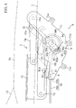
- the driving link 91 and the sector gear 92 connected via the connecting pin 93 are grasped by a guide outer 75 (shown in Fig. 8 only) and a guide inner 76 (shown in Fig. 8 only) provided opposedly each other as shown in Fig. 8 .
- a guide outer 75 shown in Fig. 8 only
- a guide inner 76 shown in Fig. 8 only
- an outer guide groove 75a is formed to said guide outer 75 , and at the same time, an inner guide groove 76a having identical profile of the outer guide groove 75a as opposed thereto is formed to the guide inner 76.
- a pair of the outer guide groove 75a and the inner guide groove 76a constitutes one guide portion 94 .
- the outer guide groove 75a and the inner guide groove 76a have a groove width which is identical to or slightly broader than the outside diameter of the connecting pin 93 and allows fitting of the connecting pin 93 in the groove 76a.
- the guide portion 94 (outer guide groove 75a and inner guide groove 76a ) has a curved shape from one end located at front lower side to other end located at rear upper side, and a non-transmitting guide portion 94a for not transmitting the driving force of the electric motor 10 to the link mechanism 7 and a transmitting guide portion 94b for transmitting the driving force of the electric motor 10 to the link mechanism 7 are continuous with each other at a switching point 94c.
- Said non-transmitting guide portion 94a is formed between one end at front lower side and the switching point 94c , and forms an arc C1 (shown in Fig. 4 only) which is drawn around the connection portion 91a in the fully closed state of trunk lid 14 , to which the driving link 91 and the rear connecting link 74 are connected, and passes the the connecting pin 93 .
- the driving link 91 simply rotates about the connection portion 91a as shown in Figs. 4 , 5 , while the connection portion 91a is not displaced.
- the rear connecting link 74 does not move and the trunk lid 14 remains motionless in fully closed state. That is, the transmitting mechanism 9 is in non-transmitting state where driving force of the electric motor 10 is not transmitted to the link mechanism 7 while the connecting pin 93 is guided along the non-transmitting guide portion 94a.
- Said transmitting guide portion 94b is formed between the switching point 94c and other end at rear upper side, and has a profile of arc C2 (shown in Fig. 4 only) passing on the connecting pin 93 while rotation center of the sector gear 92 is centered.
- the driving link 91 moves so as to displace the connection portion 91a of the driving link 91 and the rear connecting link 74 as shown in Fig. 6 , and causes the rear connecting link 74 to rotate about a vehicle side end 74a.
- the trunk lid 14 performs opening/closing operation by the link mechanism 7 (see Figs. 1 to 3 ). That is, the transmitting mechanism 9 is in transmitting state for transmitting driving force of the electric motor 10 to the link mechanism 7 while guiding the connecting pin 93 along the transmitting guide portion 94b .
- Said locking mechanism 8 includes, as shown in Fig. 4 , a hook 81 rotatably provided to said base bracket 71 , an engaging pin 82 provided to said lid side bracket 72 and engages with the hook 81 , and the lock transmitting link 83 for transmitting driving force of the electric motor 10 to the hook 81 , and holds the trunk lid 14 in fully closed state by engaging the hook 81 with the engaging pin 82 when the trunk lid 14 is in fully closed state.
- a hook portion 81a engaging with said engaging pin 82 is formed to said hook 81 .
- lock transmitting link 83 is rotatably connected to the connection portion 92b of said sector gear 92 and other end is rotatably connected to said hook 81 to transmit rotating motion of the sector gear 92 to the hook 81.
- the lock transmitting link 83 causes the hook 81 to rotate in the direction engaging with the engaging pin 82 (counterclockwise in Fig. 4 ) when the sector gear 92 drives the connecting pin 93 from switching point 94c to one end side direction along non-transmitting guide portion 94a of the guide portion 94 (clockwise in Fig. 4 ), and causes the hook 81 to rotate in the direction disengaging from the engaging pin 82 (clockwise in Fig.
- an input end of an inner cable 84b of an input cable 84 which will be dealt with later.
- the connecting pin 93 is, as shown in Fig. 4 , located at one end of front lower side of the non-transmitting guide portion 94a of the guide portion 94 . Since one end of the non-transmitting guide portion 94a side of the guide portion 94 is located at farthest position from center of rotation of the sector gear 92 in the guide portion 94, the connecting pin 93 is located at outer end of the fitting hole 92c.
- the hook portion 81a of the hook 81 is engaged with the engaging pin 82 of the lid side bracket 72 , thereby holding the trunk lid 14 in fully closed state.
- the connecting pin 93 moves the non-transmitting guide portion 94a of the guide portion 94 from one end side to the switching point 94c side in accordance with rotation of the sector gear 92. Since this non-transmitting guide portion 94a has arc C1 profile around the connection portion 91a of the driving link 91 and the rear connecting link 74 when the trunk lid 14 is fully closed, the driving link 91 simply rotates about the connection portion 91a as long as the connecting pin 93 is being guided to the non-transmitting guide portion 94a.
- connection portion 91a does not displace, the rear connecting link 74 does not move, and the trunk lid 14 remains motionless in fully closed state.
- the connecting pin 93 moves relatively in the fitting hole 92c from outer end side to inner end side as the connecting pin 93 moves along the non-transmitting guide portion 94a toward the transmitting guide portion 94b .
- the connecting pin 93 will be located at inner end of the fitting hole 92c .
- the hook 81 starts rotation from a state where the hook portion 81a is engaged with the engaging pin 82 to disengaging direction, and when the connecting pin 93 comes to the position of the switching point 94c of the guide portion 94, engagement with the engaging pin 82 is completely released. That is, the locking mechanism 8 performs unlocking operation when the transmitting mechanism 9 is in non-transmitting state.
- the connecting pin 93 When the sector gear 92 is further driven counterclockwise by driving the electric motor 10 , as shown in Fig. 6 , the connecting pin 93 will be guided along the transmitting guide portion 94b of the guide portion 94. Then, the connecting pin 93 moves being deviated from the arc C1 profile about said connection portion 91a, and therefore, the driving link 91 not only rotates about the connection portion 91a, but also moves to displace the connection portion 91a upwardly. As a result, the rear connecting link 74 rotates about the vehicle side end 74a and accordingly, the trunk lid 14 starts opening. On this occasion, the trunk lid 14 is able to perform opening/closing operation since the locking mechanism 8 is in unlocked state.
- the electric motor 10 is driven in the reverse direction (clockwise in the figure) of the direction when the trunk lid 14 is brought into fully opened state.
- the connecting pin 93 then moves on the transmitting guide portion 94b from other end side to switching point 94c side.
- the driving link 91 displaces the connection portion 91a in accordance with movement of the connecting pin 93 , and rotates the rear connecting link 74 about the vehicle side end 74a in the direction to close the trunk lid 14 .
- the trunk lid 14 starts closing.
- the trunk lid 14 When the connecting pin 93 arrives at the switching point 94c of the guide portion 94 , the trunk lid 14 is in fully closed state where the trunk room 15 is fully closed (see Fig. 5 ) .
- the connecting pin 93 passes the switching point 94c and moves along the non-transmitting guide portion 94a from switching point 94c side to one end side, i.e., when the transmitting mechanism 9 is in non-transmitting state, the hook portion 81a of said hook 81 starts engagement with the engaging pin 82 .
- the connecting pin 93 reach one end of the non-transmitting guide portion 94a, the hook portion 81a of said hook 81 is fully engaged with the engaging pin 82 to become locked state.
- the driving link 91 simply rotates about the connection portion 91a as long as the connecting pin 93 is moving along the non-transmitting guide portion 94a and the connection portion 91a is not displaced, and therefore, the trunk lid 14 remains motionless in fully closed state. That is, the locking mechanism 8 performs locking operation while the transmitting mechanism 9 is in non-transmitting state.
- the trunk rind opening/closing device 6 drives the locking mechanism 8 while the trunk lid 14 remains motionless to cause locking or unlocking operation.
- the connecting pin 93 is moved along the transmitting guide portion 94b , it causes the trunk lid 14 to perform opening/closing operation.
- the roof panel opening/closing device 2 is provided at both right and left side with respect to the roof panel 12 and the back window panel 13 and their configuration is identical, and therefore, explanation will be given for the roof panel opening/closing device 2 at the left referring to Fig. 9 to Fig. 15 .
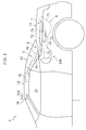
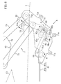
- the roof panel opening/closing device 2 includes, as shown in Fig. 9 , the link mechanism 3 for connecting the roof panel 12 , the back window panel 13 , and vehicle body 1 (see Fig. 1 ), the electric motor 4 (shown in Fig. 9 only) for driving the link mechanism 3 , a link restricting mechanism 500 for restricting the link mechanism 3 when the roof panel 12 and the back window panel 13 are in fully closed state, and a stored state locking mechanism 510 for holding the roof panel 12 when the roof panel 12 and the back window panel 13 are in stored state.
- the roof panel opening/closing device 2 causes the roof panel 12 and the back window panel 13 to perform opening/closing operation between fully closed state and stored state, restricts the link mechanism 3 in the fully closed state, and at the same time, holds the roof panel 12 in the stored state.
- a sealing material (not shown) is provided at periphery of said roof panel 12 and the back window panel 13 in order to maintain air tightness of the vehicle cabin space 11 in fully closed state.
- Said link mechanism 3 includes, as shown in Figs. 1 to 3 , a base bracket 31 provided to the vehicle body 1 , a panel side bracket 32 provided to the roof panel 12 , and the front connecting link 33 and the rear connecting link 34 for connecting the base bracket 31 and the panel side bracket 32 .
- a panel side end of said front connecting link 33 is rotatably connected to the panel side bracket 32 and a vehicle body side end of said front connecting link 33 is rotatably connected to the base bracket 31 .
- a panel side end of said rear connecting link 34 is rotatably connected to the panel side bracket 32 and a vehicle body side end of said rear connecting link 34 is rotatably connected to the base bracket 31 at backward position than the front connecting link member 33 .
- the back window panel 13 is provided to the rear connecting link 34 .
- the base bracket 31 , the panel side bracket 32, the front connecting link 33 , and the rear connecting link 34 constitute so-called four-jointed link mechanism.
- Said electric motor 14 is, as shown in Fig. 9 , provided to vehicle body side end of the front connecting link 33.
- a reduction gear 33a is provided to the vehicle body side end of the front connecting link 33
- the electric motor 4 is provided to said base bracket 31 in such that an output gear 4a provided to the output shaft thereof mates with the reduction gear 33a.
- driving force of the electric motor 4 is reduced and transmitted to the front connecting link 33 to rotate the front connecting link 33 about vehicle body side end thereof.
- the link mechanism 3 is driven to perform opening/closing operation of the roof panel 12 and the back window panel 13.
- roof panel 12 and back window panel 13 (hereafter also referred to as roof panel 12 and the like). Since the roof panel 12 and the like are opened and closed being interlocked with opening/closing operation of the trunk lid 14 , interlocking with the trunk lid 14 is also explained.
- the front connecting link 33 and the rear connecting link 34 are inclined forward being overlapped each other in the side elevation, and the roof panel 12 and the like are in fully closed state where the vehicle cabin space 11 is closed.
- the roof panel 12 is held by a locking mechanism (not shown) with respect to a front header 16 while front edge portion is in contact with the front header 16 .
- rear edge portion of the roof panel 12 and front edge portion of the back window panel 13 are in contact via the sealing member.
- the trunk lid 14 is also in fully closed state.
- the trunk lid 14 performs opening/closing operation in accordance with the movements of the roof panel 12 and the back window panel 13.
- the trunk lid 14 in order to avoid interference with opening/closing operation of the roof panel 12 and the like, when the roof panel 12 and the like move up to a position, where the roof panel 12 and the like are overlapped on opening/closing track of the trunk lid 14 , the trunk lid 14 is in opened state up to a position where it does not interfere with opening/closing track of the roof panel 12 and the like.
- the front connecting link 33 and the rear connecting link 34 are inclined backward being overlapped each other in the side elevation, and are stored in the trunk room 15 while the roof panel 12 and the back window panel 13 are folded and overlapped up and down.
- the trunk lid 14 is closed gradually following the roof panel 12 and the like being stored in the trunk room 15 , and when the roof panel 12 and the like are stored entirely in the trunk room 15 , the trunk room 15 is brought into fully closed state.
- the trunk lid 14 when opening of the trunk lid 14 is started, the roof panel 12 and the like start opening/closing operation towards fully closed state from the trunk room 15 inside. In this case, the trunk lid 14 opens so as not to interfere with the roof panel 12 and the like performing opening/closing operation towards fully closed state.
- the roof panel 12 and the back window panel 13 thus composed, a front edge portion of the roof panel 12 is held by a locking mechanism to the front header 16 in fully closed state.
- a locking mechanism to the front header 16 in fully closed state.
- the link restricting mechanism 500 for restricting movements of the link mechanism 3 in the fully closed state and the stored state locking mechanism 510 for holding the roof panel 12 in stored state are provided.
- the link restricting mechanism 500 is provided to each of the roof panel opening/closing device 2 provided at both right and left and their configuration is identical, and therefore, explanation will be given for left side link restricting mechanism 500 .
- the link restricting mechanism 500 is adapted to restrict movements of the link mechanism 3 when the roof panel 12 is in fully closed state and, as shown in Fig. 9 , includes a hook member 501 rotatably provided with respect to the base bracket 31 , a biasing spring 502 for biasing the hook member 501 from rear to front on upper side (counterclockwise in the figure, hereafter referred to as engagement direction), a first driving cable 503 for rotating the hook member 501 from front to rear on upper side against biasing force of the biasing spring 502 (clockwise in the figure, hereafter referred to as disengagement direction), and an engaging pin 504 provided to said rear connecting link 34 and engages with said hook member 501 .
- said engaging pin 504 is provided to said rear connecting link 34, it moves between fully closed position corresponding to the roof panel 12 is fully closed (position shown in Fig. 9 ) and stored position corresponding to the roof panel 12 is stored (position shown in Figs. 14 , 15 ) while drawing an arc-shaped moving track T, together with the rear connecting link 34 rotating when the roof panel 12 performs opening/closing operation.
- a hook portion 501a in hook shape, and an inner periphery 501b of the hook portion 501a (see Figs. 10, 11 ) engages with the engaging pin 504 when the roof panel 12 is in fully closed state.
- a contacting pin 505 contacting with a contacting bracket 33b provided to the front connecting link 33 when the roof panel 12 performs opening/closing operation so as to be brought into stored state, which will be explained in detail later.
- the hook member 501 thus composed is rotated in engagement direction by biasing force of the biasing spring 502 by releasing the driving of said first driving cable 503 (non-driving), and the hook portion 501a is caused to engage with the engaging pin 504 when the roof panel 12 is in fully closed state. Meanwhile, engagement of the hook portion 501a and the engaging pin 504 is disengaged by rotating the hook member 501 in disengaging direction against biasing force of the biasing spring 502 by driving of the first driving cable 503 .
- the hook member 501 constitutes the engagement member
- the biasing spring 502 constitutes the biasing member
- the first driving cable 503 constitutes the driving portion
- the engaging pin 504 constitutes the counter engaging portion.
- the hook member 501 will be explained in detail hereafter.
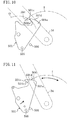
- the inner periphery 501b of the hook portion 501a of said hook member 501 has such profile that, as shown in Fig. 10 , a forefront portion 501c is opened to outside of a circumference C3 with respect to the circumference C3 passing on the hook portion 501a about rotation center of the hook member 501 .
- the hook member 501 rotates in engagement direction by biasing force of the biasing spring 502.
- a stopper 506 contacting with the hook member 501 is provided so that hook member 501 stops at a stop position where an outer periphery 501d of the hook portion 501a is located on the movement track T of the engaging pin 504, and does not rotate further.
- the hook member 501 has an inclined profile so that, when it stops at said stop position, the outer periphery 501d of the hook portion 501a is inclined with respect to the movement track T of the engaging pin 504 .
- forefront of the outer periphery 501d of the hook portion 501a is located outside the arc-shaped movement track T and is inclined with respect to the movement track T so that base end side thereof is located inside the arc-shaped movement track T .
- biasing force of the biasing spring 502 acts to the hook member 501 in engagement direction. If this disconnection occurs while the roof panel 12 is in fully closed state, engagement of the hook member 501 and the engaging pin 504 cannot be released, but the roof panel 12 can be maintained in fully closed state. Meanwhile, when the disconnection occurred while the roof panel 12 is in other than fully closed state (e.g., at stored), the hook member 501 rotates up to said stop position by biasing force of the biasing spring 502. When the roof panel 12 performs opening/closing operation towards fully closed state in this state, the engaging pin 504 rotating together with the rear connecting link 34 contacts the outer periphery 501d of the hook portion 501a.
- the engaging pin 504 moves relatively on the outer periphery 501d of the hook portion 501a from base end to forefront, and when a portion where engaging pin 504 contacts the hook portion 501a is shifted from the outer periphery 501d to the forefront portion 501c of the inner periphery, the hook member 501 starts rotation in engagement direction by biasing force of the biasing spring 502 a nd engages with the engaging pin 504 when the engaging pin 504 has moved to the fully closed position.
- the stored state locking mechanism 510 is provided to each of the roof panel opening/closing device 2 provided at both right and left and their configuration is identical, and therefore, explanation will be given for left side stored state locking mechanism 510.
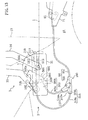
- the stored state locking mechanism 510 is adapted to hold the roof panel 12 in the trunk room 15 when the roof panel 12 is stored, and includes, as shown in Fig. 9 , an engaging bar 511 mounted to a leading guide 512 provided to the base bracket 31 and is capable of directly moving in fore and aft directions, a biasing spring 513 for biasing the engaging bar 511 backward, a second driving cable 514 for moving the engaging bar 511 forward against biasing force of the biasing spring 513 , and a counter engaging member 516 (see Figs. 1 to 3, 14, 15 ) to which is formed a counter engaging hole 515 to which said engaging bar 511 is engaged.
- Said engaging bar 511 is provided so that forefront thereof protrudes in the trunk room 15 and at a position to be inserted to the counter engaging hole 515 of the counter engaging member 516 of the roof panel 12 in stored state (see Figs. 14, 15) .
- the engaging bar 511 is moved backward (inside of trunk room 15 ) by biasing force of the biasing spring 513 by releasing the driving of the second driving cable 514 (non-driving) to cause it to engage with the counter engaging hole 515 of the counter engaging member 516 of the roof panel 12 n ow in fully closed state.
- the engaging bar 511 is moved forward (outside of trunk room 15 ) against biasing force of the biasing spring 513 by driving the second driving cable 514 to release engagement of the engaging bar 511 and the counter engaging hole 515 .
- Said link restricting mechanism 500 and the stored state locking mechanism 510 are driven by the electric motor 10 via a branched driving cable 100 .
- the branched driving cable 100 includes, as shown in Fig. 9 , an input cable 84 connected to said hook 81 , the first driving cable 503 for driving said link restricting mechanism 500 , the second driving cable 514 for driving said stored state locking mechanism 510 , and a connecting member 110 for connecting the input cable 84 , the first driving cable 503 and the second driving cable 514 .
- Said connecting member 110 is constituted by a fixing bracket 110a mounted to the vehicle body 1 and a connecting plate 110b rotatably provided to the fixing bracket 110a.
- Said input cable 84 is constituted by an outer cable 84a and an inner cable 84b slidably provided in the outer cable 84a.
- Input end of the outer cable 84a is provided to said base bracket 71 and input end of the inner cable 84b is provided to the hook 81 .
- output end of the outer cable 84a is provided to said fixing bracket 110a and an output end of the inner cable 84b is attached to part of said connecting plate 110b away from the rotation center thereof by a predetermined third distance L3.
- Said first driving cable 503 is constituted by an outer cable 503a and an inner cable 503b slidably provided in the outer cable 503a.
- Input end of the outer cable 503a is provided to the fixing bracket 110a and input end of the inner cable 503b is attached to part of said connecting plate 11b away from the rotation center thereof by a predetermined first distance L1.
- output end of the outer cable 503a is provided to the base bracket 31 and at the same time, output end of the inner cable 503b is provided to hook member 501 .
- Said second driving cable 514 is constituted by an outer cable 514a and an inner cable 514b slidably provided in the outer cable 514a.
- Input end of the outer cable 514a is provided to the fixing bracket 110a and at the same time, input end of the inner cable 514b is attached to part of said connecting plate 110b away from the rotation center thereof by a predetermined second distance L2 .
- output end of the outer cable 514a is provided to the base bracket 31 and at the same time, output end of the inner cable 514b is provided to the engaging bar 511 .
- the inner cable 84b of said input cable 84 and the inner cable 514b of the second driving cable 514 are provided at the same position with respect to the connecting plate 110b, and therefore, the second distance L2 and the third distance L3 are identical.
- Said hook 81 is driven by the electric motor 10 via the lock transmitting link 83 (see Fig. 4 ). That is, the link restricting mechanism 500 and the stored state locking mechanism 510 being driven by the branched driving cable 100 whose input end is provided to the hook 81 are driven by the electric motor 10.
- the hook 81 is in a state engaged with the engaging pin 82 and the hook member 501 is in a state engaged with the engaging pin 504 .
- the engaging bar 511 is in a state being moved backward, it is not functioning as a locking mechanism since the roof panel 12 is in fully closed state.
- the inner cable 84b of the input cable 84 is being pulled in accordance with rotation of the hook 81 .
- the connecting plate 110b connected to output end thereof rotates in one direction (counterclockwise in Fig. 8 ), and when the connecting plate 110b rotates in one direction, the inner cable 503b of the first driving cable 503 and the inner cable 514b of the second driving cable 514 are pulled.
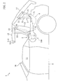
- the first driving cable 503 causes the hook member 501 to rotate in releasing direction, thereby releasing the engagement of the hook member 501 and the engaging pin 504 .
- the stored state locking mechanism 510 does not function as the locking mechanism while the roof panel 12 is in closed state, the engaging bar 511 moves forward since the second driving cable 514 is pulled.
- stroke volume input to the input cable 84 (i.e., amount the inner cable 84b is pulled) is multiplied (L1/L3) times and transmitted to the first driving cable 503, and multiplied (L2/L3) times and transmitted to the second driving cable 514 .
- the hook 81 remains being rotated in the direction of releasing the engagement with the engaging pin 82 , and therefore, the inner cable 84b of the input cable 84 remains in a state being pulled. Accordingly, the hook member 501 is held being rotated in the direction of releasing and at the same time, the engaging bar 511 is also held being moved forward.
- the roof panel 12 and the back window panel 13 are folded one above the other and are stored in the trunk room 15 .
- said transmitting mechanism 9 is brought into non-transmitting state, the locking mechanism 8 performs locking operation to lock the trunk lid 14. That is, the hook 81 rotates so as to be engaged with the engaging pin 82 . In this way, the pulling force acting on the inner cable 84b of the inner cable 84 is released and as a result, as shown in Fig. 15 , the hook member 501 rotates in engagement direction by biasing force of the biasing spring 502 and at the same time, the engaging bar 511 moves backward by biasing force of the biasing spring 513.
- the roof panel 12 is stored in the trunk room 15, and the counter engaging hole 515 of said counter engaging member 516 provided to front edge portion of the roof panel 12 is located at a position opposed to the engaging bar 511 .
- the engaging bar 511 moves backward by biasing force of the biasing spring 513, it engages with the counter engaging hole 515 to lock the roof panel 12 in stored state. That is, the stored state locking mechanism 510 functions as the locking mechanism.
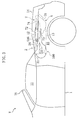
- the link restricting mechanism 500 for holding the roof panel 12 in fully closed state does not need to function as the locking mechanism. Therefore, when the roof panel 12 performs opening/closing operation towards stored state, as shown in Figs. 14 , 15 , the hook member 501 is held at a position lower than the belt line BL formed on upper periphery of the vehicle body 1 and upper periphery of the trunk lid 14 by that the hook member 501 is rotated backward (i.e., releasing direction) together with the front connecting link 33 , while said contacting bracket 33b of the front connecting link 33 rotating backward contacts with the contacting pin 505 provided to the hook member 501.
- the hook member 501 When the first driving cable 503 rotates to engagement position in non-driving state, the hook member 501 is in a state protruded upwardly from the belt line BL as shown in Fig. 8 . While the roof panel 12 is in fully closed state, the hook member 501 can not be viewed from outside the vehicle even if protruded above the belt line BL since it is hidden by the back window panel 13 . However, while the roof panel 12 is in stored state, since the back window panel 13 is stored in the trunk room 15 together with the roof panel 12 , if the hook member 501 is protruded above the belt line BL, it is viewed from outside the vehicle, thereby deteriorating beauty.
- the roof panel 12 while the roof panel 12 is in stored state, it is rotated to a position not protruding from the belt line BL, in releasing direction together with the front connecting link 33 rotating backwardly, to be held at a position hidden by the vehicle body 1 in the side elevation.
- the contacting bracket 33b constitutes the contacting portion and the contacting pin 505 constitutes the counter contacting portion.
- the roof panel 12 is held in fully closed state by the stored state locking mechanism 510 and at the same time, the trunk lid 14 is also held in fully closed state by the locking mechanism 8 .
- the hook 81 remains being rotated in the direction of releasing the engagement with the engaging pin 82 , and therefore, the inner cable 84b of the input cable 84 remains in a state being pulled. Accordingly, the hook member 501 is held being rotated in the direction of releasing and at the same time, the engaging bar 511 is also held being moved forward.
- the trunk lid 14 is also in the fully closed state, and the locking mechanism 8 performs locking operation for the trunk lid 14 in fully closed state. That is, the hook 81 rotates so as to be engaged with the engaging pin 82 . The pulling force acting on the inner cable 84b of the input cable 84 is then released, and as a result, the hook member 501 rotates in engagement direction by biasing force of the biasing spring 502 and at the same time, the engaging bar 511 moves backward by biasing force of the biasing spring 513 .
- the roof panel 12 is in fully closed state and the engaging pin 504 provided to the rear connecting link 34 is in fully closed position capable of engaging with the hook member 501. That is, when the hook member 501 rotates in the engagement direction by biasing force of the biasing spring 502 , the hook portion 501a engages with the engaging pin 504, thereby restricting the link mechanism 3 for the roof panel 12 in fully closed state.
- the link restricting mechanism 500 functions as the locking mechanism.
- the stored state locking mechanism 510 does not function as the locking mechanism while the engaging bar 511 simply moves backward.
- the roof panel 12 is held in fully closed state by the link restricting mechanism 500 and the trunk lid 14 is also held in fully closed sate by the locking mechanism 8 .
- the rear connecting link 34 can be made not rotatable with respect to the vehicle body 1 by restricting the rear connecting link 34 with respect to the vehicle body 1 by the link restricting mechanism 500 , and the link mechanism 3 can be restricted with high rigidity when the roof panel 12 is in fully closed state.
- the roof panel 12 can be held with high rigidity, thereby preventing lifting of the roof panel 12 by aerodynamic force.
- the link restricting mechanism 500 since the hook member 501 is provided to vehicle body side (base bracket 31 ) and the engaging pin 504 is provided to link side (rear connecting link 34 ), the biasing spring 502 and the first driving cable 503 can be provided to vehicle body side, which allows easy disposition of parts as compared to the configuration in which these parts are provided to link side.
- the link restricting mechanism 500 can hold the roof panel 12 back and forth in a balanced manner in cooperation with the locking mechanism of the front edge portion, thereby effectively preventing lifting of the roof panel 12.
- the hook portion 501a of the hook member 501 is formed to have such a profile that the forefront portion 501c of the inner periphery 501b thereof is opened to outside of a circumference C3 is drawn around rotation center of the hook member 501 to pass the hook portion 501a.
- the hook member 501 rotates to the stop position and stops there, and the outer periphery 501d of the hook member 501 located on the movement track T of the engaging pin 504 is inclined with respect to the movement track T as mentioned above. Therefore, even if disconnection of the first driving cable 503 occurs when the roof panel 12 is in the other state than the fully closed state, the engaging pin 504 moving along the movement track T contacts with the outer periphery 501d of the hook member 501 and presses the hook member 501 to cause rotation in releasing direction when the roof panel 12 moves to fully closed state.
- the contacting bracket 33b of the front connecting link 33 is caused to contact with the contacting pin 505 of the hook member 501 and the hook member 501 is caused to rotate backward together with the front connecting link 33 to position the hook member 501 at a position lower than the belt line BL of the vehicle body 1 and to hold it there, thereby improving the beauty.
- the present invention is not limited thereto. That is, such a configuration that the front connecting link 33 is restricted to the vehicle body 1 by the link restricting mechanism 500 may be employed. However, as mentioned previously, restriction of the rear connecting link 34 is preferable since the roof panel 12 can be held back and forth in a balanced manner.
- the present invention is useful for an opening/closing device for a roof panel for preventing lifting of the roof panel in fully closed state, which roof panel is supported by a vehicle body via a link mechanism and capable of opening and closing a vehicle cabin space.
Abstract
Description
- The present invention relates to an opening/closing device for a roof panel for preventing lifting of the roof panel in fully closed state, which room panel is supported by a vehicle body via a link mechanism and capable of opening and closing a vehicle cabin space.
- According to conventional art, there is provided a vehicle with such a configuration that a roof panel is supported by a vehicle body via a link mechanism to allow opening/closing of the roof panel (see Patent Document 1). In particular, said link mechanism includes a front connecting link member being rotatably connected to each of said roof panel and vehicle body, and a rear connecting link member being rotatably connected to each of said roof panel and vehicle body at rear side of the vehicle than the front connecting link member, thereby composing a so-called four-jointed link mechanism. The roof panel can be opened or closed with respect to the vehicle body by driving the link mechanism.
- In this vehicle, front edge portion of the roof panel is held by a front header of the vehicle body when the roof panel is in fully closed state. However, while a vehicle is running, a force to lift the roof panel upwardly is applied to the roof panel by aerodynamic force. If the force for lifting is excessive, the roof panel is lifted, and there is a possibility that airtightness between the roof panel and vehicle body is deteriorated.
- The vehicle relating to Paten
Document 1 is therefore equipped with a link restricting mechanism for restricting said link mechanism when the roof panel is in fully closed state. In particular, said link restricting mechanism includes an engaging pin provided to a front connecting link member and a hook member provided to a rear connecting link member to be engaged with the engaging pin to allow restriction of the front connecting link member and the rear connecting link member through engagement of the hook member and the engaging pin. - Thus, when the roof panel is in fully closed state, rigidity of the link mechanism is improved by restricting movements of the link mechanism, thereby suppressing lifting of the roof panel by the link mechanism.
- Paten Document: Japanese Unexamined Patent Publication No.
2002-264657 - However, each of the front connecting link member and the rear connecting link member restricted by said link restricting mechanism is a member being rotatably connected to the vehicle body and the roof panel, and there is a possibility that they rotate slightly relative to the vehicle body and the roof panel even if being restricted by said link restricting mechanism. In other words, although rigidity of the link mechanism is improved by the link restricting mechanism, rigidity obtained is not enough and still there is a room for improvement.
- The present invention has been developed in view of the above aspects, and an object of the present invention is to reliably prevent lifting of the roof panel when the roof panel is in fully closed state.
- The present invention aims to restrict either of the connecting link members of both connecting link members to the vehicle body instead of restricting rotatable connecting link members themselves.
- In particular, a first invention is an opening/closing device for a roof panel which is comprising a roof panel provided to a vehicle body, capable of opening and closing a vehicle cabin space, a link mechanism for supporting the roof panel at the vehicle body, having a front connecting link member rotatably connected to each of said vehicle body and said roof panel, and a rear connecting link member rotatably connected to each of the vehicle body and the roof panel at rear side of the vehicle relative to the front connecting link member, and a link restricting mechanism for restricting one of said front connecting link member and said rear connecting link member to the vehicle body when said roof panel is in fully closed state in which the vehicle cabin space is closed.
- With above-mentioned configuration, since one of connecting link members of the front connecting link member and the rear connecting link member constituting said link mechanism is restricted to the vehicle body by said link restricting mechanism, the one of connecting link members can be made not rotatable with respect to the vehicle body, and this allows restriction of said link mechanism with high rigidity when said roof panel is in said fully closed state. As a result, the roof panel can be held with high rigidity in fully closed state, thereby preventing the lifting of the roof panel due to aerodynamic force.
- In a second invention related to the first invention, said link restricting mechanism comprising an engaging member provided to the vehicle body, a counter engaging portion to be engaged with said engaging member, being provided to one of said front connecting link member and said rear connecting member, and a driving portion for driving the engaging member so as to engage said engaging member with said counter engaging portion and to disengage the same.
- Supposedly, if said hook member is provided to the connecting link member and said counter engaging portion is provided to the vehicle body, it is necessary to provide said driving portion and a parts relating thereto (e.g., wiring) to the connecting link member. Since the connecting link member is a rotating member, the driving portion and the parts relating thereto should be movably disposed in accordance with the connecting link member, resulting in complicated disposition.
- Then, with above-mentioned configuration, when said hook member is provided to the vehicle body, disposition of said driving portion and the parts relating thereto becomes easy.
- In a third invention related to the first or second invention, a front edge of said roof panel is configured to be supported by the vehicle body during said fully closed state, and said link restricting mechanism restricts said rear connecting link member to the vehicle body.
- With above-mentioned configuration, since the front edge portion of said roof panel is held to the vehicle body in fully closed state, lifting of the roof panel at vehicle front side occurs relatively hardly while lifting of the same at vehicle rear side occurs relatively easily. In view of the foregoing, said link restricting mechanism restricts the rear connecting link member.As a result, holding rigidity of the roof panel at more rear part of the vehicle can be improved, thereby effectively preventing the lifting of the roof panel.
- In a fourth invention related to the second invention, said engaging member has a hook portion formed in a bent hook shape and is provided to the vehicle body rotatably between an engaging position and a disengaging position, and has a biasing member for biasing the engaging member in a direction from the disengaging position to the engaging position so as to engage an inner periphery of the hooked portion with said counter engaging portion, said driving portion is configured to rotate the engaging member from the engaging position to the disengaging position against biasing force of the biasing member so as to disengage inner periphery of said hook portion from said counter engaging portion, and a front end portion of the inner periphery of said hook portion is formed in a configuration being opened towards outside with respect to a circumference, which is centered at a rotation center of said engaging member and passes over said counter engaging portion.
- With above-mentioned configuration, when said hook member is rotated, the inner periphery of the hook portion of the hook member engages with said counter engaging portion, thereby restricting said connecting link member. In this case, if the counter engaging portion has an installation error, there is a possibility that forefront of the hook portion and the counter engaging portion collide and the counter engaging portion does not engage well with inner periphery of the hook portion. In view of the foregoing, forefront part of the inner periphery of said hook portion has a profile opened outside with respect to circumference passing on said counter engaging portion while rotation center of said hook member is centered. As a result, the counter engaging portion contacts with forefront part of the inner periphery opened outside with respect to the circumference instead of forefront of the hook portion, even if the counter engaging portion has installation error, and the inner periphery of the hook portion can be reliably engaged with the counter engaging portion.
- In a fifth invention related to the second invention, said engaging member has a hook portion formed in a bent hook shape and is provided to the vehicle body rotatably between an engaging position and a disengaging position, and has a biasing member for biasing the engaging member in a direction from the disengaging position to the engaging position so as to engage an inner periphery of the hooked portion with said counter engaging portion, said driving portion is configured to rotate the engaging member from the engaging position to the disengaging position against biasing force of the biasing member so as to disengage inner periphery of said hook portion from said counter engaging portion, and an outer periphery of said hook portion is formed in a configuration having a slope shape relative to a moving track of said counter engaging portion in such a manner that, while said driving portion is in non-driving condition, said outer periphery of said hook portion is structured to be located on the movement track on which said counter engaging portion moves while said roof panel is moving toward said fully closed state, and when said counter engaging portion contacts in this state, said engaging member rotates from said engaging position to said disengaging position by a pressing force thereof.
- A vehicle equipped with an openable/closable roof panel as mentioned above keeps out wind and rain in bad weather by closing the roof panel to fully closed state. Therefore, it is necessary to provide such a measure that the roof panel brought into open state is at least brought to fully closed state for a case where said hooking mechanism or the like is broken down.
- With above-mentioned configuration, in a case said hooking mechanism or the like is broken down, rotatable driving of said driving portion stops, said hook portion rotates in one rotating direction by biasing force of said biasing member, and outer periphery of the hook portion rotates up to a position on the track on which said counter engaging portion moves when the roof panel is brought into fully closed state. When the roof panel is brought from opened state to fully closed state under this state, said counter engaging portion contacts with the outer periphery of the hook portion. Since the outer periphery of the hook portion is in said inclined profile, said hook member is rotated in said other rotating direction (disengaging direction) by the pressing force of the counter engaging portion, and as a result, when the roof panel is brought into fully closed state, the counter engaging portion is positioned inside the hook portion and at the same time, the hook member rotates in said one rotating direction (engaging direction) by the biasing member, and the counter engaging portion and the hook portion engage each other.
- In this way, even a case the hooking mechanism or the like is broken down, such a trouble that the roof panel can not be brought into fully closed state due to interference of the hook member and the counter engaging portion is prevented, and the roof panel can be brought into fully closed state.
- In a sixth invention related to the second invention, said roof panel is structured to be stored in a roof panel storage portion formed at rear part of a vehicle when said vehicle cabin space is being opened, said counter engaging portion is provided to said rear connecting link member, said engaging member has a hook portion formed in a bent hook shape and is provided to the vehicle body rotatably between an engaging position and a disengaging position, and has a biasing member for biasing the engaging member in a direction from the disengaging position to the engaging position so as to engage an inner periphery of the hook portion with said counter engaging portion, and a counter contacting portion for being contacted by said front connecting link member when said roof panel is being stored in said roof panel storage portion, said driving portion is structured to rotate the engaging member from the engaging position to the disengaging position against biasing force of the biasing member so as to disengage inner periphery of said hook portion from said counter engaging portion, and said front connecting link member has a contacting portion for contacting said counter contacting portion of said engaging member, and causes the contacting portion to contact the counter contacting portion when said roof panel is stored in the roof panel storage portion to rotate the counter engaging member against biasing force of said biasing member up to a position where the counter engaging member is not visible being hidden by the vehicle body in side elevation and to hold the same at that position.
- With above-mentioned configuration, it is preferable from viewpoint of beauty that link restricting mechanism or the like are disposed so as not to be viewed. Specifically, when the roof panel is in opened state, these members including the link mechanism should be treated suitably because the vehicle body is easy to be viewed from outside.
- In view of the foregoing, said hook member is configured not to be viewed from outside the vehicle body while the roof panel is in opened state. Particularly, said counter contacting portion is provided to the hook member, and said contacting portion is provided to the front connecting link member. Therefore, as the roof panel is stored in said roof panel storage room, the contacting portion of said front connecting link member and the counter contacting portion of the hook member make contact, and the front connecting link member causes the hook member to rotate together with the contacting portion and the counter contacting portion in contact with each other to make the hook member rotated until the hook member is hidden behind vehicle body in side elevation view. As a result, when the roof panel is stored in the roof panel storage room, the hook member is not viewed from outside the vehicle body in side elevation view, thereby improving beauty in roof panel opened state. Advantages of the Invention
- According to the present invention, rigidity of the link mechanism when the roof panel is in fully closed state can be improved because one of said front and rear connecting link members, each rotatably connected to said roof panel and vehicle body is restricted to vehicle body by said link restricting mechanism so that the link mechanism can not rotate relative to the vehicle body and roof panel. As a result, lifting of the roof panel in fully closed state can be prevented.
-
- [
Fig. 1] Fig. 1 is a schematic side view showing a vehicle employing an opening/closing device of a panel member relating to an embodiment of the present invention, in which a roof panel and a trunk lid are in fully closed state. - [
Fig. 2] Fig. 2 is a schematic side view showing the vehicle in which the roof panel and the trunk lid are in opening/closing operation. - [
Fig. 3] Fig. 3 is a schematic side view showing the vehicle in which the roof panel and the trunk lid are in stored state. - [
Fig. 4] Fig. 4 is a schematic side view showing a trunk lid opening/closing device when the trunk lid is locked in fully close state. - [
Fig. 5] Fig. 5 is a schematic side view showing the trunk lid opening/closing device when the trunk lid is lock released in fully close state. - [
Fig. 6] Fig. 6 is a schematic side view showing the trunk lid opening/closing device when the trunk lid is in opening/closing operation. - [
Fig. 7] Fig. 7 is a schematic side view showing the trunk lid opening/closing device when the trunk lid is in fully opened state. - [
Fig. 8] Fig. 8 is an exploded perspective view showing the trunk lid opening/closing device. - [
Fig. 9] Fig. 9 is a schematic side view showing the roof panel opening/closing device when the roof panel is locked in fully closed state. - [
Fig. 10] Fig. 10 is a schematic side view showing the profile of an inner periphery of a hook portion of a hook member. - [
Fig. 11] Fig. 11 is a schematic side view showing the profile of an outer periphery of the hook portion of the hook member. - [
Fig. 12] Fig. 12 is a schematic side view showing the roof panel opening/closing device when the roof panel is lock-released in fully closed state. - [
Fig. 13] Fig. 13 is a schematic side view showing the roof panel opening/closing device when the roof panel is in opening/closing operation. - [
Fig. 14] Fig. 14 is a schematic side view showing the roof panel opening/closing device when the roof panel is stored in a trunk room. - [
Fig. 15] Fig. 15 is a schematic side view showing the roof panel opening/closing device when the roof panel is locked in the trunk room and is in stored state. -
- C3
- circumference
- T
- moving track (track)
- 1
- vehicle body
- 11
- vehicle cabin space
- 12
- roof panel
- 15
- trunk room (roof panel storage portion)
- 3
- link mechanism
- 33
- front connecting link (front connecting link member)
- 33b
- contacting bracket (contacting portion)
- 34
- rear connecting link (rear connecting link member)
- 500
- link restricting mechanism
- 501
- hook member (engaging member)
- 501a
- hook portion
- 501b
- inner periphery
- 501d
- outer periphery
- 502
- biasing spring (biasing member)
- 503
- first driving cable (driving portion)
- 504
- engaging pin (counter engaging portion)
- 505
- contacting pin (counter contacting portion)
- Referring now to the drawings, the embodiment of the present invention will be explained hereafter in detail.
- For simplicity of explanation, in the explanation of the embodiment, front side of the vehicle is referred to as "front", rear side of the vehicle is referred to as "rear", left side of vehicle width direction is referred to as "left", and right side of vehicle width direction is referred to as "right".
-
Fig.1 shows vehicle V having a trunk lid relating to the embodiment of the present invention.Reference numeral 12 is a roof panel provided to thevehicle body 1,reference numeral 13 is a back window panel provided to thevehicle body 1, andreference numeral 14 is a trunk lid for opening/closing atrunk room 15 being formed to vehicle rear part of thevehicle body 1. - Said
roof panel 12 and theback window panel 13 are configured to be openable/closable by a roof panel opening/closing device 2 between fully closed state where avehicle cabin space 11 of thevehicle body 1 is closed as shown inFig. 1 and stored state (fully opened state) stored in atrunk room 15 provided to vehicle body rear part as shown inFig. 3 . In the present embodiment, thetrunk room 15 corresponds to the roof panel storage portion. However, a roof panel storage portion for storing theroof panel 12 and theback window panel 13 may be provided separately from the trunk room. - Further, said
trunk lid 14 is configured to be openable/closable between fully closed state where thetrunk room 15 is closed and fully opened where thetrunk room 15 is made open by a trunk lid opening/closing device 6. Thistrunk lid 14 performs opening/closing operation being interlocked with opening/closing operation of saidroof panel 12 and theback window panel 13. That is, when saidroof panel 12 and theback window panel 13 are in fully closed state or stored state, thetrunk lid 14 is in fully closed state (seeFigs. 1 and3 ), while when saidroof panel 12 and theback window panel 13 are performing opening/closing operation from fully closed state to stored state, or performing opening/closing operation in reverse direction, it is in a state where thetrunk room 15 is made open (seeFig. 2 ). - First, the trunk lid opening/
closing device 6 will be explained. Although the trunk lid opening/closing device 6 is provided at both right and left side with respect to thetrunk lid 14, their configuration is identical, and therefore, explanation will be given for the trunk lid opening/closing device 6 at the left referring toFig. 4 to Fig. 8 . - The trunk rind opening/
closing device 6 includes alink mechanism 7 for connecting thetrunk lid 14 and thevehicle body 1, alocking mechanism 8 for holding thetrunk lid 14 in fully closed state, an electric motor 10 (not shown inFigs. 5 to 7 ) for driving thelink mechanism 7 and thelocking mechanism 8, and atransmitting mechanism 9 for transmitting a driving force of theelectric motor 10 to thelink mechanism 7, causes thetrunk lid 14 to perform opening/closing operation between fully closed state and fully opened state, and at the same time, holds thetrunk lid 14 to the vehicle body in fully closed state. - Said
link mechanism 7 includes abase bracket 71 provided to thevehicle body 1, alid side bracket 72 provided to thetrunk lid 14, and a front connectinglink 73 and arear connecting link 74 for connecting thebase bracket 71 and thelid side bracket 72. - Said
base bracket 71 includes mountingbrackets brackets vehicle body 1 from the inside of the vehicle cabin. - Lid side end of said
front connecting link 73 is rotatably connected to thelid side bracket 72 and vehicle side end of saidfront connecting link 73 is rotatably connected to thebase bracket 71. Further, lid side end of saidrear connecting link 74 is rotatably connected to thelid side bracket 72 and vehicle side end of saidrear connecting link 74 is rotatably connected to thebase bracket 71 at backward position than the front connectinglink member 73. - In this way, the
base bracket 71, thelid side bracket 72, the front connectinglink member 73, andrear connecting link 74 constitute so-called four-jointed link mechanism, and rotation of the front connectinglink member 73 and therear connecting link 74 about each of vehicle side end causes thetrunk lid 14 to perform opening/closing operation. - Said transmitting
mechanism 9 includes a drivinglink 91 one end of which is connected to saidrear connecting link 74, asector gear 92 rotatably driven being connected to theelectric motor 10, and a connectingpin 93 for connecting other end of the drivinglink 91 and thesector gear 92, and is so composed that transmitting state where driving force of theelectric motor 10 is transmitted to thelink mechanism 7 and non-transmitting state where the driving force is not transmitted to thelink mechanism 7 are switchable. - One end of said driving
link 91 is rotatably connected to saidrear connecting link 74 at aconnection portion 91a, while to other end is penetrated an insertinghole 91b (seeFig. 8 ) through which said connectingpin 93 is passed. - To said
sector gear 92 are integrally formed agear portion 92a mating with an output gear (not shown) provided to an output shaft of saidelectric motor 10 and aconnection portion 92b to which other end of said drivinglink 91 is connected. Saidgear portion 92a has gear ratio to reduce driving force of theelectric motor 10 with respect to the output gear, i.e., thesector gear 92 functions also as a reduction gear. To saidconnection portion 92b is penetrated afitting hole 92c in oblong shape extending in radial direction with respect to center of rotation of thesector gear 92. - Then, by fitting the connecting
pin 93 passed through the insertinghole 91b of said drivinglink 91 into thefitting hole 92c of saidsector gear 92, the drivinglink 91 is rotatably connected to thesector gear 92 and is displaceably connected in the direction of extension of the oblong hole of thefitting hole 92c. Although the connectingpin 93 is rotatably provided to the drivinglink 91 by insertion through the insertinghole 91b of the drivinglink 91, the connectingpin 93 may be fixed to the drivinglink 91 by welding. Further, thefitting hole 92c need not be penetrated necessarily, and any configuration with closed bottom may be used as long as the connectingpin 93 can be fit thereto. - The driving
link 91 and thesector gear 92 connected via the connectingpin 93 are grasped by a guide outer 75 (shown inFig. 8 only) and a guide inner 76 (shown inFig. 8 only) provided opposedly each other as shown inFig. 8 . When the guide outer 75 is provided to thebase bracket 71, the drivinglink 91, thesector gear 92, the connectingpin 93 or the like are then provided to thebase bracket 71. - Here, an
outer guide groove 75a is formed to said guide outer 75, and at the same time, aninner guide groove 76a having identical profile of theouter guide groove 75a as opposed thereto is formed to the guide inner 76. A pair of theouter guide groove 75a and theinner guide groove 76a constitutes oneguide portion 94. Meanwhile, theouter guide groove 75a and theinner guide groove 76a have a groove width which is identical to or slightly broader than the outside diameter of the connectingpin 93 and allows fitting of the connectingpin 93 in thegroove 76a. - Specifically, when said driving
link 91 and thesector gear 92 are grasped by the guide outer 75 and the guide inner 76, thesector gear 92 is rotatably supported with respect to the guide outer 75 and the guide inner 76 and at the same time, each of both ends of the connectingpin 93 penetrating through the drivinglink 91 and thesector gear 92 is engaged with theouter guide groove 75a and theinner guide groove 76a. Further, theelectric motor 10 is mounted to the guide inner 76 so that an output gear of the output shaft thereof mates with thegear portion 92a of thesector gear 92. Meanwhile, to theconnection portion 92b of thesector gear 92 is connected alock transmitting link 83, which will be dealt with later, in addition to said drivinglink 91. - With the
transmitting mechanism 9 thus composed, when thesector gear 92 is rotatably driven by theelectric motor 10, the drivinglink 91 connected to thesector gear 92 by the connectingpin 93 is driven. On this occasion, since the connectingpin 93 is engaged with theguide portion 94, the drivinglink 91 is driven while the connectingpin 93 is being guided by theguide portion 94. - Profile of said
guide portion 94 will be explained in detail. The guide portion 94 (outer guide groove 75a andinner guide groove 76a) has a curved shape from one end located at front lower side to other end located at rear upper side, and anon-transmitting guide portion 94a for not transmitting the driving force of theelectric motor 10 to thelink mechanism 7 and a transmittingguide portion 94b for transmitting the driving force of theelectric motor 10 to thelink mechanism 7 are continuous with each other at aswitching point 94c. - Said
non-transmitting guide portion 94a is formed between one end at front lower side and theswitching point 94c, and forms an arc C1 (shown inFig. 4 only) which is drawn around theconnection portion 91a in the fully closed state oftrunk lid 14, to which the drivinglink 91 and therear connecting link 74 are connected, and passes the the connectingpin 93. In other words, when the connectingpin 93 is guided along thenon-transmitting guide portion 94a, the drivinglink 91 simply rotates about theconnection portion 91a as shown inFigs. 4 ,5 , while theconnection portion 91a is not displaced. As a result, therear connecting link 74 does not move and thetrunk lid 14 remains motionless in fully closed state. That is, thetransmitting mechanism 9 is in non-transmitting state where driving force of theelectric motor 10 is not transmitted to thelink mechanism 7 while the connectingpin 93 is guided along thenon-transmitting guide portion 94a. - Said transmitting
guide portion 94b is formed between theswitching point 94c and other end at rear upper side, and has a profile of arc C2 (shown inFig. 4 only) passing on the connectingpin 93 while rotation center of thesector gear 92 is centered. In other words, when the connectingpin 93 is guided along the transmittingguide portion 94b, the drivinglink 91 moves so as to displace theconnection portion 91a of the drivinglink 91 and therear connecting link 74 as shown inFig. 6 , and causes therear connecting link 74 to rotate about avehicle side end 74a. As a result, thetrunk lid 14 performs opening/closing operation by the link mechanism 7 (seeFigs. 1 to 3 ). That is, thetransmitting mechanism 9 is in transmitting state for transmitting driving force of theelectric motor 10 to thelink mechanism 7 while guiding the connectingpin 93 along the transmittingguide portion 94b. - Said
locking mechanism 8 includes, as shown inFig. 4 , ahook 81 rotatably provided to saidbase bracket 71, an engagingpin 82 provided to saidlid side bracket 72 and engages with thehook 81, and thelock transmitting link 83 for transmitting driving force of theelectric motor 10 to thehook 81, and holds thetrunk lid 14 in fully closed state by engaging thehook 81 with the engagingpin 82 when thetrunk lid 14 is in fully closed state. - A
hook portion 81a engaging with said engagingpin 82 is formed to saidhook 81 . - One end of said
lock transmitting link 83 is rotatably connected to theconnection portion 92b of saidsector gear 92 and other end is rotatably connected to saidhook 81 to transmit rotating motion of thesector gear 92 to thehook 81. Thelock transmitting link 83 causes thehook 81 to rotate in the direction engaging with the engaging pin 82 (counterclockwise inFig. 4 ) when thesector gear 92 drives the connectingpin 93 from switchingpoint 94c to one end side direction alongnon-transmitting guide portion 94a of the guide portion 94 (clockwise inFig. 4 ), and causes thehook 81 to rotate in the direction disengaging from the engaging pin 82 (clockwise inFig. 4 ) when thesector gear 92 drives the connectingpin 93 from one end side to theswitching point 94c direction alongnon-transmitting guide portion 94a of the guide portion 94 (counterclockwise inFig. 4 ). Meanwhile, when thesector gear 92 is guided the connectingpin 93 along the transmittingguide portion 94b of theguide portion 94, thehook 81 rotates in accordance with rotation of thesector gear 92 regardless of engagement of the engagingpin 82. - Further, to the
hook 81 is provided an input end of aninner cable 84b of aninput cable 84 which will be dealt with later. - Operations of the
trunk lid 14 and thelocking mechanism 8 driven by the trunk lid opening/closing device 6 thus composed will be explained hereafter. - First, when the
trunk lid 14 is in fully closed state, the connectingpin 93 is, as shown inFig. 4 , located at one end of front lower side of thenon-transmitting guide portion 94a of theguide portion 94. Since one end of thenon-transmitting guide portion 94a side of theguide portion 94 is located at farthest position from center of rotation of thesector gear 92 in theguide portion 94, the connectingpin 93 is located at outer end of thefitting hole 92c. - In the meantime, the
hook portion 81a of thehook 81 is engaged with the engagingpin 82 of thelid side bracket 72, thereby holding thetrunk lid 14 in fully closed state. - When the
sector gear 92 is turned counterclockwise by driving theelectric motor 10 from this state, as shown inFig. 5 , the connectingpin 93 moves thenon-transmitting guide portion 94a of theguide portion 94 from one end side to theswitching point 94c side in accordance with rotation of thesector gear 92. Since thisnon-transmitting guide portion 94a has arc C1 profile around theconnection portion 91a of the drivinglink 91 and therear connecting link 74 when thetrunk lid 14 is fully closed, the drivinglink 91 simply rotates about theconnection portion 91a as long as the connectingpin 93 is being guided to thenon-transmitting guide portion 94a. In other words, since theconnection portion 91a does not displace, therear connecting link 74 does not move, and thetrunk lid 14 remains motionless in fully closed state. Further, since a distance between thenon-transmitting guide portion 94a and rotation center of thesector gear 92 becomes shorter as it comes closer to theswitching point 94c, the connectingpin 93 moves relatively in thefitting hole 92c from outer end side to inner end side as the connectingpin 93 moves along thenon-transmitting guide portion 94a toward the transmittingguide portion 94b. When the connectingpin 93 reaches theswitching point 94c, the connectingpin 93 will be located at inner end of thefitting hole 92c. - In the meantime, the
hook 81 starts rotation from a state where thehook portion 81a is engaged with the engagingpin 82 to disengaging direction, and when the connectingpin 93 comes to the position of theswitching point 94c of theguide portion 94, engagement with the engagingpin 82 is completely released. That is, thelocking mechanism 8 performs unlocking operation when thetransmitting mechanism 9 is in non-transmitting state. - When the
sector gear 92 is further driven counterclockwise by driving theelectric motor 10, as shown inFig. 6 , the connectingpin 93 will be guided along the transmittingguide portion 94b of theguide portion 94. Then, the connectingpin 93 moves being deviated from the arc C1 profile about saidconnection portion 91a, and therefore, the drivinglink 91 not only rotates about theconnection portion 91a, but also moves to displace theconnection portion 91a upwardly. As a result, therear connecting link 74 rotates about thevehicle side end 74a and accordingly, thetrunk lid 14 starts opening. On this occasion, thetrunk lid 14 is able to perform opening/closing operation since thelocking mechanism 8 is in unlocked state. - Meanwhile, engagement of the
hook 81 with the engagingpin 82 is already released and it further rotates in the engagement releasing direction in accordance with rotation of thesector gear 92 regardless of engagement with the engagingpin 82. - When the connecting
pin 93 finally moves to other end of rear upper side in the transmittingguide portion 94b of theguide portion 94 as shown inFig. 7 , thetrunk lid 14 is brought into fully opened state (seeFig. 2 ). - Contrary, when the
trunk lid 14 is brought from fully opened state to fully closed state, the operation from fully closed state to fully opened state as mentioned above is reversed. - First, the
electric motor 10 is driven in the reverse direction (clockwise in the figure) of the direction when thetrunk lid 14 is brought into fully opened state. The connectingpin 93 then moves on the transmittingguide portion 94b from other end side to switchingpoint 94c side. The drivinglink 91 displaces theconnection portion 91a in accordance with movement of the connectingpin 93, and rotates therear connecting link 74 about thevehicle side end 74a in the direction to close thetrunk lid 14. As a result, thetrunk lid 14 starts closing. - When the connecting
pin 93 arrives at theswitching point 94c of theguide portion 94, thetrunk lid 14 is in fully closed state where thetrunk room 15 is fully closed (seeFig. 5 ). - After that, when the connecting
pin 93 passes theswitching point 94c and moves along thenon-transmitting guide portion 94a from switchingpoint 94c side to one end side, i.e., when thetransmitting mechanism 9 is in non-transmitting state, thehook portion 81a of saidhook 81 starts engagement with the engagingpin 82. When the connectingpin 93 reach one end of thenon-transmitting guide portion 94a, thehook portion 81a of saidhook 81 is fully engaged with the engagingpin 82 to become locked state. As mentioned above, the drivinglink 91 simply rotates about theconnection portion 91a as long as the connectingpin 93 is moving along thenon-transmitting guide portion 94a and theconnection portion 91a is not displaced, and therefore, thetrunk lid 14 remains motionless in fully closed state. That is, thelocking mechanism 8 performs locking operation while thetransmitting mechanism 9 is in non-transmitting state. - In this way, when the connecting
pin 93 is moved along thenon-transmitting guide portion 94a, the trunk rind opening/closing device 6 drives thelocking mechanism 8 while thetrunk lid 14 remains motionless to cause locking or unlocking operation. When the connectingpin 93 is moved along the transmittingguide portion 94b, it causes thetrunk lid 14 to perform opening/closing operation. - Next, the roof panel opening/
closing device 2 will be explained. The roof panel opening/closing device 2 is provided at both right and left side with respect to theroof panel 12 and theback window panel 13 and their configuration is identical, and therefore, explanation will be given for the roof panel opening/closing device 2 at the left referring toFig. 9 to Fig. 15 . - The roof panel opening/
closing device 2 includes, as shown inFig. 9 , thelink mechanism 3 for connecting theroof panel 12, theback window panel 13, and vehicle body 1 (seeFig. 1 ), the electric motor 4 (shown inFig. 9 only) for driving thelink mechanism 3, alink restricting mechanism 500 for restricting thelink mechanism 3 when theroof panel 12 and theback window panel 13 are in fully closed state, and a storedstate locking mechanism 510 for holding theroof panel 12 when theroof panel 12 and theback window panel 13 are in stored state. The roof panel opening/closing device 2 causes theroof panel 12 and theback window panel 13 to perform opening/closing operation between fully closed state and stored state, restricts thelink mechanism 3 in the fully closed state, and at the same time, holds theroof panel 12 in the stored state. - A sealing material (not shown) is provided at periphery of said
roof panel 12 and theback window panel 13 in order to maintain air tightness of thevehicle cabin space 11 in fully closed state. - Said
link mechanism 3 includes, as shown inFigs. 1 to 3 , abase bracket 31 provided to thevehicle body 1, apanel side bracket 32 provided to theroof panel 12, and thefront connecting link 33 and therear connecting link 34 for connecting thebase bracket 31 and thepanel side bracket 32. - A panel side end of said
front connecting link 33 is rotatably connected to thepanel side bracket 32 and a vehicle body side end of saidfront connecting link 33 is rotatably connected to thebase bracket 31. Further, a panel side end of saidrear connecting link 34 is rotatably connected to thepanel side bracket 32 and a vehicle body side end of saidrear connecting link 34 is rotatably connected to thebase bracket 31 at backward position than the front connectinglink member 33. Theback window panel 13 is provided to therear connecting link 34. - In this way, the
base bracket 31, thepanel side bracket 32, thefront connecting link 33, and therear connecting link 34 constitute so-called four-jointed link mechanism. - Said
electric motor 14 is, as shown inFig. 9 , provided to vehicle body side end of the front connectinglink 33. Specifically, areduction gear 33a is provided to the vehicle body side end of the front connectinglink 33, and theelectric motor 4 is provided to saidbase bracket 31 in such that anoutput gear 4a provided to the output shaft thereof mates with thereduction gear 33a. In this way, driving force of theelectric motor 4 is reduced and transmitted to thefront connecting link 33 to rotate thefront connecting link 33 about vehicle body side end thereof. Thus thelink mechanism 3 is driven to perform opening/closing operation of theroof panel 12 and theback window panel 13. - The following description explains opening/closing operation of the
roof panel 12 and back window panel 13 (hereafter also referred to asroof panel 12 and the like). Since theroof panel 12 and the like are opened and closed being interlocked with opening/closing operation of thetrunk lid 14, interlocking with thetrunk lid 14 is also explained. - First, in fully closed state, as shown in
Fig. 1 , thefront connecting link 33 and therear connecting link 34 are inclined forward being overlapped each other in the side elevation, and theroof panel 12 and the like are in fully closed state where thevehicle cabin space 11 is closed. In this case, theroof panel 12 is held by a locking mechanism (not shown) with respect to afront header 16 while front edge portion is in contact with thefront header 16. Further, rear edge portion of theroof panel 12 and front edge portion of theback window panel 13 are in contact via the sealing member. - In this case, the
trunk lid 14 is also in fully closed state. - When said
electric motor 4 is driven from this state, as shown inFig. 2 , thefront connecting link 33 starts backward rotation, theroof panel 12 and the like starts backward rotation in accordance with this movement and open thevehicle cabin space 11. Since theroof panel 12 is mounted to thepanel side bracket 32 and theback window panel 13 is mounted to therear connecting link 34, as thepanel side bracket 32 and therear connecting link 34 are folded by rotation of thelink mechanism 3, theback window panel 13 is being folded with respect to theroof panel 12. - On this occasion, the
trunk lid 14 performs opening/closing operation in accordance with the movements of theroof panel 12 and theback window panel 13. In particular, as shown inFig. 2 , in order to avoid interference with opening/closing operation of theroof panel 12 and the like, when theroof panel 12 and the like move up to a position, where theroof panel 12 and the like are overlapped on opening/closing track of thetrunk lid 14, thetrunk lid 14 is in opened state up to a position where it does not interfere with opening/closing track of theroof panel 12 and the like. - Finally, as shown in
Fig. 3 , thefront connecting link 33 and therear connecting link 34 are inclined backward being overlapped each other in the side elevation, and are stored in thetrunk room 15 while theroof panel 12 and theback window panel 13 are folded and overlapped up and down. - In this case, the
trunk lid 14 is closed gradually following theroof panel 12 and the like being stored in thetrunk room 15, and when theroof panel 12 and the like are stored entirely in thetrunk room 15, thetrunk room 15 is brought into fully closed state. - In contrast, when it is brought from stored state to fully closed state, above-mentioned opening/closing operation from fully closed state to stored state is reversed.
- First, when opening of the
trunk lid 14 is started, theroof panel 12 and the like start opening/closing operation towards fully closed state from thetrunk room 15 inside. In this case, thetrunk lid 14 opens so as not to interfere with theroof panel 12 and the like performing opening/closing operation towards fully closed state. - When the
roof panel 12 and the like arrive at a position where theroof panel 12 does not overlap the opening/closing track of thetrunk lid 14, thetrunk lid 14 starts closing. Meanwhile, theroof panel 12 and the like continue movement towards fully closed state. - Finally, the
roof panel 12 and the like and thetrunk lid 14 are brought into fully closed state nearly simultaneously. - Subsequently, a mechanism for holding the
roof panel 12 and the like will be explained. - With the
roof panel 12 and theback window panel 13 thus composed, a front edge portion of theroof panel 12 is held by a locking mechanism to thefront header 16 in fully closed state. However, when the vehicle is traveling, there is a possibility that they are lifted by uplifting force due to aerodynamic force or vibration. Even in stored state, there is a possibility that theroof panel 12 and the like jounce in thetrunk room 15 due to vibrations. Several mechanisms are then required to hold theroof panel 12 and the like appropriately. In the present embodiment, thelink restricting mechanism 500 for restricting movements of thelink mechanism 3 in the fully closed state and the storedstate locking mechanism 510 for holding theroof panel 12 in stored state are provided. - First, the
link restricting mechanism 500 will be explained. Thelink restricting mechanism 500 is provided to each of the roof panel opening/closing device 2 provided at both right and left and their configuration is identical, and therefore, explanation will be given for left sidelink restricting mechanism 500. - The
link restricting mechanism 500 is adapted to restrict movements of thelink mechanism 3 when theroof panel 12 is in fully closed state and, as shown inFig. 9 , includes ahook member 501 rotatably provided with respect to thebase bracket 31, a biasingspring 502 for biasing thehook member 501 from rear to front on upper side (counterclockwise in the figure, hereafter referred to as engagement direction), afirst driving cable 503 for rotating thehook member 501 from front to rear on upper side against biasing force of the biasing spring 502 (clockwise in the figure, hereafter referred to as disengagement direction), and anengaging pin 504 provided to saidrear connecting link 34 and engages with saidhook member 501. - Since said engaging
pin 504 is provided to saidrear connecting link 34, it moves between fully closed position corresponding to theroof panel 12 is fully closed (position shown inFig. 9 ) and stored position corresponding to theroof panel 12 is stored (position shown inFigs. 14 ,15 ) while drawing an arc-shaped moving track T, together with therear connecting link 34 rotating when theroof panel 12 performs opening/closing operation. - To said
hook member 501 is formed ahook portion 501a in hook shape, and aninner periphery 501b of thehook portion 501a (seeFigs. 10, 11 ) engages with theengaging pin 504 when theroof panel 12 is in fully closed state. To thehook member 501 is provided a contactingpin 505 contacting with a contactingbracket 33b provided to thefront connecting link 33 when theroof panel 12 performs opening/closing operation so as to be brought into stored state, which will be explained in detail later. - The
hook member 501 thus composed is rotated in engagement direction by biasing force of the biasingspring 502 by releasing the driving of said first driving cable 503 (non-driving), and thehook portion 501a is caused to engage with theengaging pin 504 when theroof panel 12 is in fully closed state. Meanwhile, engagement of thehook portion 501a and theengaging pin 504 is disengaged by rotating thehook member 501 in disengaging direction against biasing force of the biasingspring 502 by driving of thefirst driving cable 503. - Engagement of the
hook member 501 and theengaging pin 504 thus obtained restricts therear connecting link 34 with respect to thevehicle body 1, and theroof panel 12 is held in fully closed state by this configuration. In the present embodiment, thehook member 501 constitutes the engagement member, the biasingspring 502 constitutes the biasing member, thefirst driving cable 503 constitutes the driving portion, and theengaging pin 504 constitutes the counter engaging portion. - The
hook member 501 will be explained in detail hereafter. Theinner periphery 501b of thehook portion 501a of saidhook member 501 has such profile that, as shown inFig. 10 , aforefront portion 501c is opened to outside of a circumference C3 with respect to the circumference C3 passing on thehook portion 501a about rotation center of thehook member 501. With this configuration, even if the position of theengaging pin 504 is slightly shifted from original fully closed position when theroof panel 12 is fully closed state due to error at mounting theengaging pin 504 to therear connecting link 34 or error of engagingpin 504 itself, theforefront portion 501c of thehook portion 501a reliably contacts theengaging pin 504 when thehook member 501 rotates in engagement direction, and theengaging pin 504 can be reliably engaged with theinner periphery 501b of thehook portion 501a. - Further, in an event the
first driving cable 503 is disconnected by any chance, thehook member 501 rotates in engagement direction by biasing force of the biasingspring 502. However, as shown inFig. 11 , astopper 506 contacting with thehook member 501 is provided so thathook member 501 stops at a stop position where anouter periphery 501d of thehook portion 501a is located on the movement track T of theengaging pin 504, and does not rotate further. Thehook member 501 has an inclined profile so that, when it stops at said stop position, theouter periphery 501d of thehook portion 501a is inclined with respect to the movement track T of theengaging pin 504. In other words, forefront of theouter periphery 501d of thehook portion 501a is located outside the arc-shaped movement track T and is inclined with respect to the movement track T so that base end side thereof is located inside the arc-shaped movement track T. - That is, when the
first driving cable 503 is disconnected, biasing force of the biasingspring 502 acts to thehook member 501 in engagement direction. If this disconnection occurs while theroof panel 12 is in fully closed state, engagement of thehook member 501 and theengaging pin 504 cannot be released, but theroof panel 12 can be maintained in fully closed state. Meanwhile, when the disconnection occurred while theroof panel 12 is in other than fully closed state (e.g., at stored), thehook member 501 rotates up to said stop position by biasing force of the biasingspring 502. When theroof panel 12 performs opening/closing operation towards fully closed state in this state, the engagingpin 504 rotating together with therear connecting link 34 contacts theouter periphery 501d of thehook portion 501a. Since, in this case, theouter periphery 501d is inclined as mentioned above, a pressing force when theengaging pin 504 moves towards fully closed position (seeFig. 8 ) acts on thehook member 501 so as to rotate thehook member 501 in releasing direction. As a result, the engagingpin 504 moves to fully closed position along the movement track T in accordance with opening/closing operation of theroof panel 12 towards fully closed state while causing thehook member 501 to rotate in releasing direction. In this case, the engagingpin 504 moves relatively on theouter periphery 501d of thehook portion 501a from base end to forefront, and when a portion where engagingpin 504 contacts thehook portion 501a is shifted from theouter periphery 501d to theforefront portion 501c of the inner periphery, thehook member 501 starts rotation in engagement direction by biasing force of the biasingspring 502 and engages with theengaging pin 504 when theengaging pin 504 has moved to the fully closed position. - In this way, even if the
first driving cable 503 is disconnected, with such a configuration that thehook member 501 is caused to rotate in releasing direction by pressing force of theengaging pin 504 moving towards fully closed state when theroof panel 12 is brought into fully closed state to allow engagement of thehook member 501 and theengaging pin 504, such a situation that theengaging pin 504 interferes with thehook member 501 when theroof panel 12 performs opening/closing operation towards fully closed state, and movement to fully closed state is not possible, can be prevented, thereby reliably bringing theroof panel 12 into fully closed state. - Next, the stored
state locking mechanism 510 will be explained. The storedstate locking mechanism 510 is provided to each of the roof panel opening/closing device 2 provided at both right and left and their configuration is identical, and therefore, explanation will be given for left side storedstate locking mechanism 510. - The stored
state locking mechanism 510 is adapted to hold theroof panel 12 in thetrunk room 15 when theroof panel 12 is stored, and includes, as shown inFig. 9 , an engagingbar 511 mounted to aleading guide 512 provided to thebase bracket 31 and is capable of directly moving in fore and aft directions, a biasingspring 513 for biasing the engagingbar 511 backward, asecond driving cable 514 for moving the engagingbar 511 forward against biasing force of the biasingspring 513, and a counter engaging member 516 (seeFigs. 1 to 3, 14, 15 ) to which is formed acounter engaging hole 515 to which said engagingbar 511 is engaged. - Said engaging
bar 511 is provided so that forefront thereof protrudes in thetrunk room 15 and at a position to be inserted to thecounter engaging hole 515 of thecounter engaging member 516 of theroof panel 12 in stored state (seeFigs. 14, 15) . - Specifically, the engaging
bar 511 is moved backward (inside of trunk room 15) by biasing force of the biasingspring 513 by releasing the driving of the second driving cable 514 (non-driving) to cause it to engage with thecounter engaging hole 515 of thecounter engaging member 516 of theroof panel 12 now in fully closed state. In the meantime, the engagingbar 511 is moved forward (outside of trunk room 15) against biasing force of the biasingspring 513 by driving thesecond driving cable 514 to release engagement of the engagingbar 511 and thecounter engaging hole 515. - Said
link restricting mechanism 500 and the storedstate locking mechanism 510 are driven by theelectric motor 10 via a branched drivingcable 100. - The branched driving
cable 100 includes, as shown inFig. 9 , aninput cable 84 connected to saidhook 81, thefirst driving cable 503 for driving saidlink restricting mechanism 500, thesecond driving cable 514 for driving said storedstate locking mechanism 510, and a connectingmember 110 for connecting theinput cable 84, thefirst driving cable 503 and thesecond driving cable 514. - Said connecting
member 110 is constituted by a fixingbracket 110a mounted to thevehicle body 1 and a connectingplate 110b rotatably provided to the fixingbracket 110a. -
Said input cable 84 is constituted by anouter cable 84a and aninner cable 84b slidably provided in theouter cable 84a. Input end of theouter cable 84a is provided to saidbase bracket 71 and input end of theinner cable 84b is provided to thehook 81. Meanwhile, output end of theouter cable 84a is provided to said fixingbracket 110a and an output end of theinner cable 84b is attached to part of said connectingplate 110b away from the rotation center thereof by a predetermined third distance L3. - Said first driving
cable 503 is constituted by anouter cable 503a and aninner cable 503b slidably provided in theouter cable 503a. Input end of theouter cable 503a is provided to the fixingbracket 110a and input end of theinner cable 503b is attached to part of said connecting plate 11b away from the rotation center thereof by a predetermined first distance L1. Meanwhile, output end of theouter cable 503a is provided to thebase bracket 31 and at the same time, output end of theinner cable 503b is provided to hookmember 501. - Said second driving
cable 514 is constituted by anouter cable 514a and aninner cable 514b slidably provided in theouter cable 514a. Input end of theouter cable 514a is provided to the fixingbracket 110a and at the same time, input end of theinner cable 514b is attached to part of said connectingplate 110b away from the rotation center thereof by a predetermined second distance L2. In the meantime, output end of theouter cable 514a is provided to thebase bracket 31 and at the same time, output end of theinner cable 514b is provided to the engagingbar 511. In the present embodiment, theinner cable 84b of saidinput cable 84 and theinner cable 514b of thesecond driving cable 514 are provided at the same position with respect to the connectingplate 110b, and therefore, the second distance L2 and the third distance L3 are identical. - Said
hook 81 is driven by theelectric motor 10 via the lock transmitting link 83 (seeFig. 4 ). That is, thelink restricting mechanism 500 and the storedstate locking mechanism 510 being driven by the branched drivingcable 100 whose input end is provided to thehook 81 are driven by theelectric motor 10. - The following description explains operations of the
link restricting mechanism 500 and the storedstate locking mechanism 510 being interlocked with operations of thehook 81. - First, when the
roof panel 12 is in fully closed state, as shown inFigs. 4 ,9 , thehook 81 is in a state engaged with the engagingpin 82 and thehook member 501 is in a state engaged with theengaging pin 504. Although the engagingbar 511 is in a state being moved backward, it is not functioning as a locking mechanism since theroof panel 12 is in fully closed state. - When the
electric motor 10 is driven, from this state, in a direction for releasing engagement of thehook 81 and the engagingpin 82, as shown inFig. 12 , theinner cable 84b of theinput cable 84 is being pulled in accordance with rotation of thehook 81. When theinner cable 84b is pulled, the connectingplate 110b connected to output end thereof rotates in one direction (counterclockwise inFig. 8 ), and when the connectingplate 110b rotates in one direction, theinner cable 503b of thefirst driving cable 503 and theinner cable 514b of thesecond driving cable 514 are pulled. As a result, thefirst driving cable 503 causes thehook member 501 to rotate in releasing direction, thereby releasing the engagement of thehook member 501 and theengaging pin 504. Further, as mentioned above, although the storedstate locking mechanism 510 does not function as the locking mechanism while theroof panel 12 is in closed state, the engagingbar 511 moves forward since thesecond driving cable 514 is pulled. - In this way, a pulling force accompanied by rotation of the
hook 81 is transmitted to thelink restricting mechanism 500 and the storedstate locking mechanism 510 via the branched drivingcable 100. Here, since input end of theinner cable 503b of thefirst driving cable 503 and input end of theinner cable 514b of thesecond driving cable 514 are attached to part of the connectingplate 110b away from rotation center thereof by the first distance L1 and the second distance L2, respectively, the pulling force being input from theinput cable 84 is transmitted to thefirst driving cable 503 and thesecond driving cable 514 being distributed with a ratio of L1 : L2. Further, from viewpoint of stroke volume, since input end of theinner cable 503b of thefirst driving cable 503, input end of theinner cable 514b of thesecond driving cable 514, and output end of theinner cable 84b of theinput cable 84 are attached to part of the connectingplate 110b away from rotation center thereof by the first distance L1, second distance L2, and third distance L3, respectively, stroke volume input to the input cable 84 (i.e., amount theinner cable 84b is pulled) is multiplied (L1/L3) times and transmitted to thefirst driving cable 503, and multiplied (L2/L3) times and transmitted to thesecond driving cable 514. - In this way, when restriction of the
link mechanism 3 by thelink restricting mechanism 500 is released, as shown inFig. 13 , theelectric motor 4 is driven, and thefront connecting link 33 and therear connecting link 34 start backward rotation. - While the
roof panel 12 performs opening/closing operation from fully closed state to stored state, i.e., while thetrunk lid 14 is once brought from fully closed state to opened state and brought again to fully closed state, thehook 81 remains being rotated in the direction of releasing the engagement with the engagingpin 82, and therefore, theinner cable 84b of theinput cable 84 remains in a state being pulled. Accordingly, thehook member 501 is held being rotated in the direction of releasing and at the same time, the engagingbar 511 is also held being moved forward. - In due course of time, as shown in
Fig. 14 , theroof panel 12 and theback window panel 13 are folded one above the other and are stored in thetrunk room 15. After that, when thetrunk lid 14 is brought into fully closed state, said transmittingmechanism 9 is brought into non-transmitting state, thelocking mechanism 8 performs locking operation to lock thetrunk lid 14. That is, thehook 81 rotates so as to be engaged with the engagingpin 82. In this way, the pulling force acting on theinner cable 84b of theinner cable 84 is released and as a result, as shown inFig. 15 , thehook member 501 rotates in engagement direction by biasing force of the biasingspring 502 and at the same time, the engagingbar 511 moves backward by biasing force of the biasingspring 513. - On this occasion, the
roof panel 12 is stored in thetrunk room 15, and thecounter engaging hole 515 of saidcounter engaging member 516 provided to front edge portion of theroof panel 12 is located at a position opposed to the engagingbar 511. In other words, when the engagingbar 511 moves backward by biasing force of the biasingspring 513, it engages with thecounter engaging hole 515 to lock theroof panel 12 in stored state. That is, the storedstate locking mechanism 510 functions as the locking mechanism. - In the meantime, while the
roof panel 12 is stored, thelink restricting mechanism 500 for holding theroof panel 12 in fully closed state does not need to function as the locking mechanism. Therefore, when theroof panel 12 performs opening/closing operation towards stored state, as shown inFigs. 14 ,15 , thehook member 501 is held at a position lower than the belt line BL formed on upper periphery of thevehicle body 1 and upper periphery of thetrunk lid 14 by that thehook member 501 is rotated backward (i.e., releasing direction) together with the front connectinglink 33, while said contactingbracket 33b of the front connectinglink 33 rotating backward contacts with the contactingpin 505 provided to thehook member 501. - When the
first driving cable 503 rotates to engagement position in non-driving state, thehook member 501 is in a state protruded upwardly from the belt line BL as shown inFig. 8 . While theroof panel 12 is in fully closed state, thehook member 501 can not be viewed from outside the vehicle even if protruded above the belt line BL since it is hidden by theback window panel 13. However, while theroof panel 12 is in stored state, since theback window panel 13 is stored in thetrunk room 15 together with theroof panel 12, if thehook member 501 is protruded above the belt line BL, it is viewed from outside the vehicle, thereby deteriorating beauty. Therefore, as mentioned above, while theroof panel 12 is in stored state, it is rotated to a position not protruding from the belt line BL, in releasing direction together with the front connectinglink 33 rotating backwardly, to be held at a position hidden by thevehicle body 1 in the side elevation. In the present embodiment, the contactingbracket 33b constitutes the contacting portion and the contactingpin 505 constitutes the counter contacting portion. - In this way, the
roof panel 12 is held in fully closed state by the storedstate locking mechanism 510 and at the same time, thetrunk lid 14 is also held in fully closed state by thelocking mechanism 8. - In the meantime, when the
roof panel 12 performs opening/closing operation from stored state to fully closed state, theelectric motor 10 is driven and, first, disengagement of thehook 81 and the engagingpin 82 is carried out. Since this operation results in pulling of theinner cable 84b of theinner cable 84, thehook member 501 is caused to rotate in releasing direction and at the same time, the engagingbar 511 is caused to move forward. As a result, engagement of the engagingbar 511 and counter engaginghole 515 is released. In this way, unlocking operation of thelocking mechanism 8 for holding thetrunk lid 14 and the same of the storedstate locking mechanism 510 holding theroof panel 12 are carried out at the same time. - While the
roof panel 12 performs opening/closing operation from stored state to fully closed state, i.e., while thetrunk lid 14 is once brought from fully closed state to opened state and brought again to fully closed state, thehook 81 remains being rotated in the direction of releasing the engagement with the engagingpin 82, and therefore, theinner cable 84b of theinput cable 84 remains in a state being pulled. Accordingly, thehook member 501 is held being rotated in the direction of releasing and at the same time, the engagingbar 511 is also held being moved forward. - In due course of time, when front edge portion of the
roof panel 12 contacts with thefront header 16 and theroof panel 12 is brought into fully closed state, thetrunk lid 14 is also in the fully closed state, and thelocking mechanism 8 performs locking operation for thetrunk lid 14 in fully closed state. That is, thehook 81 rotates so as to be engaged with the engagingpin 82. The pulling force acting on theinner cable 84b of theinput cable 84 is then released, and as a result, thehook member 501 rotates in engagement direction by biasing force of the biasingspring 502 and at the same time, the engagingbar 511 moves backward by biasing force of the biasingspring 513. - On this occasion, the
roof panel 12 is in fully closed state and theengaging pin 504 provided to therear connecting link 34 is in fully closed position capable of engaging with thehook member 501. That is, when thehook member 501 rotates in the engagement direction by biasing force of the biasingspring 502, thehook portion 501a engages with theengaging pin 504, thereby restricting thelink mechanism 3 for theroof panel 12 in fully closed state. In other words, thelink restricting mechanism 500 functions as the locking mechanism. - In the meantime, since the
roof panel 12 is brought into fully closed state and does not exist in thetrunk room 15, the storedstate locking mechanism 510 does not function as the locking mechanism while the engagingbar 511 simply moves backward. - In this way, the
roof panel 12 is held in fully closed state by thelink restricting mechanism 500 and thetrunk lid 14 is also held in fully closed sate by thelocking mechanism 8. - Therefore, according to above-shown embodiment, the
rear connecting link 34 can be made not rotatable with respect to thevehicle body 1 by restricting therear connecting link 34 with respect to thevehicle body 1 by thelink restricting mechanism 500, and thelink mechanism 3 can be restricted with high rigidity when theroof panel 12 is in fully closed state. As a result, theroof panel 12 can be held with high rigidity, thereby preventing lifting of theroof panel 12 by aerodynamic force. - Further, in the
link restricting mechanism 500, since thehook member 501 is provided to vehicle body side (base bracket 31) and theengaging pin 504 is provided to link side (rear connecting link 34), the biasingspring 502 and thefirst driving cable 503 can be provided to vehicle body side, which allows easy disposition of parts as compared to the configuration in which these parts are provided to link side. - Further, of the
link mechanism 3, since therear connecting link 34 instead of the front connectinglink 33 is restricted to thevehicle body 1, holding rigidity of rear portion of theroof panel 12 can be improved, front edge portion of which is held to thefront header 16 in fully closed state. As a result, thelink restricting mechanism 500 can hold theroof panel 12 back and forth in a balanced manner in cooperation with the locking mechanism of the front edge portion, thereby effectively preventing lifting of theroof panel 12. - Furthermore, since the
hook portion 501a of thehook member 501 is formed to have such a profile that theforefront portion 501c of theinner periphery 501b thereof is opened to outside of a circumference C3 is drawn around rotation center of thehook member 501 to pass thehook portion 501a. even if theengaging pin 504 is located at a position slightly shifted from original fully closed position when theroof panel 12 is fully closed state due to error at mounting of theengaging pin 504 to therear connecting link 34 or shape error of theengaging pin 504 itself, when thehook member 501 rotates in engagement direction, theforefront portion 501c of thehook portion 501a contacts reliably with theengaging pin 504, and theengaging pin 504 can be engaged with theinner periphery 501b of thehook portion 501a. In other words, when theforefront portion 501c of theinner periphery 501b of thehook portion 501a is formed to have a profile opened to outside with respect to the circumference C3, installation error of theengaging pin 504 and own shape error are absorbed, thereby allowing reliable engagement. - Further, when the
first driving cable 503 is disconnected by any chance, thehook member 501 rotates to the stop position and stops there, and theouter periphery 501d of thehook member 501 located on the movement track T of theengaging pin 504 is inclined with respect to the movement track T as mentioned above. Therefore, even if disconnection of thefirst driving cable 503 occurs when theroof panel 12 is in the other state than the fully closed state, the engagingpin 504 moving along the movement track T contacts with theouter periphery 501d of thehook member 501 and presses thehook member 501 to cause rotation in releasing direction when theroof panel 12 moves to fully closed state. As a result, such a trouble that, when theroof panel 12 performs opening/closing operation towards fully closed state, the engagingpin 504 interferes with thehook member 501 and movement till fully closed state is not possible can be prevented, and even if thefirst driving cable 503 is disconnected by any chance, theroof panel 12 can be brought reliably into fully closed state. - Further, when the
roof panel 12 and the like are stored in thetrunk room 15, the contactingbracket 33b of the front connectinglink 33 is caused to contact with the contactingpin 505 of thehook member 501 and thehook member 501 is caused to rotate backward together with the front connectinglink 33 to position thehook member 501 at a position lower than the belt line BL of thevehicle body 1 and to hold it there, thereby improving the beauty. - Although in the above shown embodiment, of the
link mechanism 3, therear connecting link 34 is restricted to thevehicle body 1 by thelink restricting mechanism 500, the present invention is not limited thereto. That is, such a configuration that thefront connecting link 33 is restricted to thevehicle body 1 by thelink restricting mechanism 500 may be employed. However, as mentioned previously, restriction of therear connecting link 34 is preferable since theroof panel 12 can be held back and forth in a balanced manner. - As described hereinbefore, the present invention is useful for an opening/closing device for a roof panel for preventing lifting of the roof panel in fully closed state, which roof panel is supported by a vehicle body via a link mechanism and capable of opening and closing a vehicle cabin space.
Claims (6)
- An opening/closing device for a roof panel comprising:a roof panel provided to a vehicle body, capable of opening and closing a vehicle cabin space;a link mechanism for supporting the roof panel at the vehicle body, having a front connecting link member rotatably connected to each of said vehicle body and said roof panel, and a rear connecting link member rotatably connected to each of the vehicle body and the roof panel at rear side of the vehicle relative to the front connecting link member; anda link restricting mechanism for restricting one of said front connecting link member andsaid rear connecting link member to the vehicle body when said roof panel is in fully closed state in which the vehicle cabin space is closed.
- The opening/closing device for the roof panel according to claim 1, characterized in that said link restricting mechanism comprising:an engaging member provided to the vehicle body;a counter engaging portion to be engaged with said engaging member, being provided to one of said front connecting link member and said rear connecting member; anda driving portion for driving the engaging member so as to engage said engaging member with said counter engaging portion and to disengage the same.
- The opening/closing device for the roof panel according to claim 1 or 2, characterized in that:a front edge of said roof panel is configured to be supported by the vehicle body during said fully closed state; andsaid link restricting mechanism restricts said rear connecting link member to the vehicle body.
- The opening/closing device for the roof panel according to claim 2 characterized in that:said engaging member has a hook portion formed in a bent hook shape and is provided to the vehicle body rotatably between an engaging position and a disengaging position, andhas a biasing member for biasing the engaging member in a direction from the disengaging position to the engaging position so as to engage an inner periphery of the hooked portion with said counter engaging portion;said driving portion is configured to rotate the engaging member from the engaging position to the disengaging position against biasing force of the biasing member so as to disengage inner periphery of said hook portion from said counter engaging portion; anda front end portion of the inner periphery of said hook portion is formed in a configuration being opened towards outside with respect to a circumference, which is centered at a rotation center of said engaging member and passes over said counter engaging portion.
- The opening/closing device for the roof panel according to claim 2 characterized in that:said engaging member has a hook portion formed in a bent hook shape and is provided to the vehicle body rotatably between an engaging position and a disengaging position, andhas a biasing member for biasing the engaging member in a direction from the disengaging position to the engaging position so as to engage an inner periphery of the hooked portion with said counter engaging portion;said driving portion is configured to rotate the engaging member from the engaging position to the disengaging position against biasing force of the biasing member so as to disengage inner periphery of said hook portion from said counter engaging portion; andan outer periphery of said hook portion is formed in a configuration having a slope shape relative to a moving track of said counter engaging portion in such a manner that, while said driving portion is in non-driving condition, said outer periphery of said hook portion is structured to be located on the movement track on which said counter engaging portion moves while said roof panel is moving toward said fully closed state, and when said counter engaging portion contacts in this state, said engaging member rotates from said engaging position to said disengaging position by a pressing force thereof.
- The opening/closing device for the roof panel according to claim 2 characterized in that:said roof panel is structured to be stored in a roof panel storage portion formed at rear part of a vehicle when said vehicle cabin space is being opened;said counter engaging portion is provided to said rear connecting link member;said engaging member has a hook portion formed in a bent hook shape and is provided to the vehicle body rotatably between an engaging position and a disengaging position, andhas a biasing member for biasing the engaging member in a direction from the disengaging position to the engaging position so as to engage an inner periphery of the hook portion with said counter engaging portion, and a counter contacting portion for being contacted by said front connecting link member when said roof panel is being stored in said roof panel storage portion;said driving portion is structured to rotate the engaging member from the engaging position to the disengaging position against biasing force of the biasing member so as to disengage inner periphery of said hook portion from said counter engaging portion; andsaid front connecting link member has a contacting portion for contacting said counter contacting portion of said engaging member, and causes the contacting portion to contact the counter contacting portion when said roof panel is stored in the roof panel storage portion to rotate the counter engaging member against biasing force of said biasing member up to a position where the counter engaging member is not visible being hidden by the vehicle body in side elevation and to hold the same at that position.
Applications Claiming Priority (2)
| Application Number | Priority Date | Filing Date | Title |
|---|---|---|---|
| JP2006088838A JP4922639B2 (en) | 2006-03-28 | 2006-03-28 | Roof panel opening and closing device |
| PCT/JP2007/056577 WO2007114137A1 (en) | 2006-03-28 | 2007-03-28 | Opening/closing device for roof panel |
Publications (4)
| Publication Number | Publication Date |
|---|---|
| EP2006137A2 EP2006137A2 (en) | 2008-12-24 |
| EP2006137A9 true EP2006137A9 (en) | 2009-07-22 |
| EP2006137A4 EP2006137A4 (en) | 2010-02-24 |
| EP2006137B1 EP2006137B1 (en) | 2012-08-08 |
Family
ID=38563406
Family Applications (1)
| Application Number | Title | Priority Date | Filing Date |
|---|---|---|---|
| EP07740015A Active EP2006137B1 (en) | 2006-03-28 | 2007-03-28 | Opening/closing device for roof panel |
Country Status (4)
| Country | Link |
|---|---|
| US (1) | US7837250B2 (en) |
| EP (1) | EP2006137B1 (en) |
| JP (1) | JP4922639B2 (en) |
| WO (1) | WO2007114137A1 (en) |
Families Citing this family (3)
| Publication number | Priority date | Publication date | Assignee | Title |
|---|---|---|---|---|
| JP2007261407A (en) * | 2006-03-28 | 2007-10-11 | Webasto Japan Kk | Retractable roof, and vehicle provided with the same |
| DE102018114807B4 (en) * | 2018-06-20 | 2021-09-02 | Webasto SE | Convertible top with two links connected by a coupling link |
| GB201818324D0 (en) | 2018-11-09 | 2018-12-26 | Mclaren Automotive Ltd | Retractable roof |
Family Cites Families (10)
| Publication number | Priority date | Publication date | Assignee | Title |
|---|---|---|---|---|
| FR1079044A (en) * | 1952-02-15 | 1954-11-25 | Carbodies Ltd | Convertible car body with folding top and suitable for semi-lifting |
| IT215012Z2 (en) * | 1988-07-11 | 1990-07-30 | Pininfarina Ind Spa | FLEXIBLE COVER FOR VEHICLES WITH OPENING ROOF EQUIPPED WITH SAFETY HOOK FOR THE REAR ARC OF THE COVER FRAME |
| DE3830393C1 (en) * | 1988-09-07 | 1989-08-24 | Daimler-Benz Aktiengesellschaft, 7000 Stuttgart, De | |
| DE3914638A1 (en) * | 1989-05-03 | 1990-11-08 | Scharwaechter Gmbh Co Kg | FOLDING COVER FOR MOTOR VEHICLES |
| US6508502B2 (en) * | 2001-02-08 | 2003-01-21 | Asc Incorporated | Convertible roof and tonneau cover system |
| JP3636306B2 (en) * | 2001-03-13 | 2005-04-06 | アイシン精機株式会社 | Retractable roof |
| JP4045810B2 (en) * | 2002-02-12 | 2008-02-13 | マツダ株式会社 | Upper body structure of the vehicle |
| DE10213548B4 (en) | 2002-03-26 | 2009-01-02 | Webasto Ag | Cabriolet vehicle with loading facilitation |
| DE10315100B3 (en) | 2003-04-02 | 2004-12-09 | Cts Fahrzeug-Dachsysteme Gmbh | Passenger accident protection system for vehicles has a roof which is pre-tensioned in the direction of the side facing away from the vehicle cabin when the system is activated |
| US7658008B2 (en) * | 2004-02-27 | 2010-02-09 | Magna Car Top Systems Gmbh | Injection molded magnesium convertible top stack |
-
2006
- 2006-03-28 JP JP2006088838A patent/JP4922639B2/en active Active
-
2007
- 2007-03-28 EP EP07740015A patent/EP2006137B1/en active Active
- 2007-03-28 WO PCT/JP2007/056577 patent/WO2007114137A1/en active Application Filing
- 2007-03-28 US US12/295,180 patent/US7837250B2/en active Active
Also Published As
| Publication number | Publication date |
|---|---|
| EP2006137B1 (en) | 2012-08-08 |
| JP4922639B2 (en) | 2012-04-25 |
| EP2006137A4 (en) | 2010-02-24 |
| JP2007261419A (en) | 2007-10-11 |
| EP2006137A2 (en) | 2008-12-24 |
| US20090160225A1 (en) | 2009-06-25 |
| WO2007114137A1 (en) | 2007-10-11 |
| US7837250B2 (en) | 2010-11-23 |
Similar Documents
| Publication | Publication Date | Title |
|---|---|---|
| US8870582B2 (en) | Charging port cover and charging port structure | |
| US7125063B2 (en) | Lid mechanism and center console box | |
| EP0952930B1 (en) | A vehicle tailgate | |
| EP2006140B1 (en) | Opening/closing system for roof panel and separated drive cable used for the same | |
| EP2392755A2 (en) | Lid opening and closing apparatus | |
| EP2623352A1 (en) | Arrangement structure for charging port cover | |
| US6131337A (en) | Vehicle door closing apparatus | |
| US20080309127A1 (en) | Supporting Device for a Soft Top Compartment Cover of a Convertible | |
| EP2006137A9 (en) | Opening/closing device for roof panel | |
| EP2090729A2 (en) | Door lock system | |
| JP4833710B2 (en) | Panel member opening and closing device | |
| JP4369588B2 (en) | Fuel lid device | |
| US11680435B2 (en) | Single drive system for driving multiple driven assemblies | |
| JP4767993B2 (en) | Open roof structure for vehicles | |
| CN217197722U (en) | Sliding door connecting mechanism and automobile | |
| JPS60244631A (en) | Seat device in automobile | |
| JP4790766B2 (en) | Open roof structure for vehicles | |
| JP4157094B2 (en) | Open roof structure for vehicles | |
| US11505049B2 (en) | Locking device comprising a link mechanism and a slide | |
| JPH0268220A (en) | Canvas stop for automobile | |
| JPH0721450U (en) | Back eye camera storage device | |
| JPH0373487B2 (en) | ||
| JP2001039341A (en) | Holding mechanism for half-opened luggage door |
Legal Events
| Date | Code | Title | Description |
|---|---|---|---|
| PUAI | Public reference made under article 153(3) epc to a published international application that has entered the european phase |
Free format text: ORIGINAL CODE: 0009012 |
|
| PUAB | Information related to the publication of an a document modified or deleted |
Free format text: ORIGINAL CODE: 0009199EPPU |
|
| 17P | Request for examination filed |
Effective date: 20081027 |
|
| AK | Designated contracting states |
Kind code of ref document: A2 Designated state(s): DE FR GB IT |
|
| RBV | Designated contracting states (corrected) |
Designated state(s): DE FR GB IT |
|
| A4 | Supplementary search report drawn up and despatched |
Effective date: 20100127 |
|
| DAX | Request for extension of the european patent (deleted) | ||
| 17Q | First examination report despatched |
Effective date: 20100512 |
|
| REG | Reference to a national code |
Ref country code: DE Ref legal event code: R079 Ref document number: 602007024568 Country of ref document: DE Free format text: PREVIOUS MAIN CLASS: B60J0007120000 Ipc: B60J0007185000 |
|
| GRAP | Despatch of communication of intention to grant a patent |
Free format text: ORIGINAL CODE: EPIDOSNIGR1 |
|
| RIC1 | Information provided on ipc code assigned before grant |
Ipc: B60J 7/185 20060101AFI20120203BHEP Ipc: B60J 7/14 20060101ALI20120203BHEP Ipc: B60J 7/19 20060101ALI20120203BHEP |
|
| GRAS | Grant fee paid |
Free format text: ORIGINAL CODE: EPIDOSNIGR3 |
|
| GRAA | (expected) grant |
Free format text: ORIGINAL CODE: 0009210 |
|
| AK | Designated contracting states |
Kind code of ref document: B1 Designated state(s): DE FR GB IT |
|
| REG | Reference to a national code |
Ref country code: GB Ref legal event code: FG4D |
|
| REG | Reference to a national code |
Ref country code: DE Ref legal event code: R096 Ref document number: 602007024568 Country of ref document: DE Effective date: 20120927 |
|
| PG25 | Lapsed in a contracting state [announced via postgrant information from national office to epo] |
Ref country code: IT Free format text: LAPSE BECAUSE OF FAILURE TO SUBMIT A TRANSLATION OF THE DESCRIPTION OR TO PAY THE FEE WITHIN THE PRESCRIBED TIME-LIMIT Effective date: 20120808 |
|
| PLBE | No opposition filed within time limit |
Free format text: ORIGINAL CODE: 0009261 |
|
| STAA | Information on the status of an ep patent application or granted ep patent |
Free format text: STATUS: NO OPPOSITION FILED WITHIN TIME LIMIT |
|
| 26N | No opposition filed |
Effective date: 20130510 |
|
| REG | Reference to a national code |
Ref country code: DE Ref legal event code: R097 Ref document number: 602007024568 Country of ref document: DE Effective date: 20130510 |
|
| REG | Reference to a national code |
Ref country code: FR Ref legal event code: PLFP Year of fee payment: 10 |
|
| REG | Reference to a national code |
Ref country code: FR Ref legal event code: PLFP Year of fee payment: 11 |
|
| REG | Reference to a national code |
Ref country code: FR Ref legal event code: PLFP Year of fee payment: 12 |
|
| PGFP | Annual fee paid to national office [announced via postgrant information from national office to epo] |
Ref country code: GB Payment date: 20200325 Year of fee payment: 14 |
|
| PGFP | Annual fee paid to national office [announced via postgrant information from national office to epo] |
Ref country code: FR Payment date: 20200324 Year of fee payment: 14 |
|
| GBPC | Gb: european patent ceased through non-payment of renewal fee |
Effective date: 20210328 |
|
| PG25 | Lapsed in a contracting state [announced via postgrant information from national office to epo] |
Ref country code: GB Free format text: LAPSE BECAUSE OF NON-PAYMENT OF DUE FEES Effective date: 20210328 Ref country code: FR Free format text: LAPSE BECAUSE OF NON-PAYMENT OF DUE FEES Effective date: 20210331 |
|
| PGFP | Annual fee paid to national office [announced via postgrant information from national office to epo] |
Ref country code: DE Payment date: 20230320 Year of fee payment: 17 |