EP2006114A9 - Thermal recording device, image forming method and printed matter - Google Patents
Thermal recording device, image forming method and printed matter Download PDFInfo
- Publication number
- EP2006114A9 EP2006114A9 EP07740040A EP07740040A EP2006114A9 EP 2006114 A9 EP2006114 A9 EP 2006114A9 EP 07740040 A EP07740040 A EP 07740040A EP 07740040 A EP07740040 A EP 07740040A EP 2006114 A9 EP2006114 A9 EP 2006114A9
- Authority
- EP
- European Patent Office
- Prior art keywords
- image data
- image
- produce
- printed
- processing
- Prior art date
- Legal status (The legal status is an assumption and is not a legal conclusion. Google has not performed a legal analysis and makes no representation as to the accuracy of the status listed.)
- Granted
Links
Images


Classifications
-
- B—PERFORMING OPERATIONS; TRANSPORTING
- B41—PRINTING; LINING MACHINES; TYPEWRITERS; STAMPS
- B41J—TYPEWRITERS; SELECTIVE PRINTING MECHANISMS, i.e. MECHANISMS PRINTING OTHERWISE THAN FROM A FORME; CORRECTION OF TYPOGRAPHICAL ERRORS
- B41J2/00—Typewriters or selective printing mechanisms characterised by the printing or marking process for which they are designed
- B41J2/315—Typewriters or selective printing mechanisms characterised by the printing or marking process for which they are designed characterised by selective application of heat to a heat sensitive printing or impression-transfer material
- B41J2/32—Typewriters or selective printing mechanisms characterised by the printing or marking process for which they are designed characterised by selective application of heat to a heat sensitive printing or impression-transfer material using thermal heads
- B41J2/35—Typewriters or selective printing mechanisms characterised by the printing or marking process for which they are designed characterised by selective application of heat to a heat sensitive printing or impression-transfer material using thermal heads providing current or voltage to the thermal head
- B41J2/355—Control circuits for heating-element selection
- B41J2/36—Print density control
- B41J2/365—Print density control by compensation for variation in temperature
-
- B—PERFORMING OPERATIONS; TRANSPORTING
- B41—PRINTING; LINING MACHINES; TYPEWRITERS; STAMPS
- B41J—TYPEWRITERS; SELECTIVE PRINTING MECHANISMS, i.e. MECHANISMS PRINTING OTHERWISE THAN FROM A FORME; CORRECTION OF TYPOGRAPHICAL ERRORS
- B41J2/00—Typewriters or selective printing mechanisms characterised by the printing or marking process for which they are designed
- B41J2/005—Typewriters or selective printing mechanisms characterised by the printing or marking process for which they are designed characterised by bringing liquid or particles selectively into contact with a printing material
- B41J2/01—Ink jet
-
- B—PERFORMING OPERATIONS; TRANSPORTING
- B41—PRINTING; LINING MACHINES; TYPEWRITERS; STAMPS
- B41J—TYPEWRITERS; SELECTIVE PRINTING MECHANISMS, i.e. MECHANISMS PRINTING OTHERWISE THAN FROM A FORME; CORRECTION OF TYPOGRAPHICAL ERRORS
- B41J2/00—Typewriters or selective printing mechanisms characterised by the printing or marking process for which they are designed
- B41J2/315—Typewriters or selective printing mechanisms characterised by the printing or marking process for which they are designed characterised by selective application of heat to a heat sensitive printing or impression-transfer material
- B41J2/32—Typewriters or selective printing mechanisms characterised by the printing or marking process for which they are designed characterised by selective application of heat to a heat sensitive printing or impression-transfer material using thermal heads
- B41J2/35—Typewriters or selective printing mechanisms characterised by the printing or marking process for which they are designed characterised by selective application of heat to a heat sensitive printing or impression-transfer material using thermal heads providing current or voltage to the thermal head
- B41J2/355—Control circuits for heating-element selection
- B41J2/36—Print density control
Definitions
- the present invention relates to a thermal recording apparatus or the like which reduces effects of heat accumulated in a thermal head and prints highly fine hairline images and circular hairlines by a low resolution.
- a thermal printer is an apparatus which heats the back of an ink ribbon superimposed on a recording paper by means of a thermal head in order to thermally transfer the ink of the ink ribbon onto the recording paper, to thereby print an image on the paper.
- the ink ribbon is a thermal transfer sheet including a layer of thermally meltable color ink
- the recording paper is an image-receiving sheet such as a sheet of paper or a plastic sheet.
- the thermal head is a composed of a plurality of heat-generating resistors formed on a substrate in a row.
- the thermal printer includes a plurality of ink ribbons corresponding to a plurality of colors.
- the inks of the ink ribbons of the plurality of colors are transferred in a superimposed state onto the recording paper at the same position, to thereby perform color printing.
- the ink ribbons are disposed to be rotatable, and an ink ribbon to undergo thermal transfer is moved to the position of the thermal head.
- a recording-paper feed apparatus feeds the recording paper to the position of the thermal head, which is a printing position, whereby printing is effected in a predetermined image-printing area of the recording paper.
- a hairline pattern which is a pattern composed of a large number of thin lines (hairlines) extending along a specific direction.
- a method for consistently obtaining a clear hairline pattern has been known (see, for example, Patent Document 1).
- hairlines and hairline gaps are arranged on a drawing line of interest; a determination is made as to whether the hairline gaps arranged on the drawing line of interest are adjacent to the hairline gaps of a determined drawing line on which hairlines and hairline gaps have already been arranged; the drawing line of interest is treated as a determined drawing line only when none of the hairline gaps of the drawing line of interest is located adjacent to the hairline gaps of the determined drawing line; and the generation and arrangement of hairlines and hairline gaps for the drawing line of interest are performed once more when any of the hairline gaps of the drawing line of interest is located adjacent to the hairline gaps of the determined drawing line.
- Patent Document 1 Japanese Patent Application Laid-Open ( kokai ) No. 2002-221781
- Patent Document 2 Japanese Patent Application Laid-Open ( kokai ) No. H6-202445
- the above-described first method requires complicated calculation for formation of hairlines.
- the above-described second method is peculiar to an image forming apparatus which forms a color image, in a transfer scheme or a direct scheme, by repeating an image forming process including a step (primary charging) of uniformly charging an image bearing body such as a photosensitive body or a dielectric body. Therefore, the second method cannot be applied to a thermal recording apparatus or the like.
- the present invention has been accomplished in view of such problems, and an object of the present invention is to provide a thermal recording apparatus or the like which reduces effects of heat accumulated in a thermal head and prints highly fine hairline images and circular hairlines by a low resolution.
- a first invention for achieving the above-described object is a printed matter obtained by performing shift processing for second image data, which are obtained from first image data through gradation conversion and halftone conversion, to thereby produce third image data; performing rotation processing for said third image data to thereby produce fourth image data; performing heat-accumulation correction processing for said third image data and said fourth image data to thereby produce fifth image data and sixth image data; and printing the fifth image data and the sixth image data on an object to be printed by a thermal recording apparatus including a thermal head.
- finer hairlines can be printed at a low resolution.
- a second invention is a thermal recording apparatus comprising means for performing shift processing for second image data, which are obtained from first image data through gradation conversion and halftone conversion, to thereby produce third image data; means for performing rotation processing for said third image data to thereby produce fourth image data; means for performing heat-accumulation correction processing for said third image data and said fourth image data to thereby produce fifth image data and sixth image data; and means for printing the fifth image data and the sixth image data on an object to be printed.
- a third invention is an image forming method comprising the steps of performing shift processing for second image data, which are obtained from first image data through gradation conversion and halftone conversion, to thereby produce third image data; performing rotation processing for said third image data to thereby produce fourth image data; performing heat-accumulation correction processing for said third image data and said fourth image data to thereby produce fifth image data and sixth image data; and printing the fifth image data and the sixth image data on an object to be printed by a thermal recording apparatus including a thermal head.
- a fourth invention is a printed matter obtained by producing first image data for forming a pattern; producing, from said first image data, second image data for forming a second pattern; performing shift processing for said second image data to thereby produce third image data; performing polar coordinate conversion for said second image data and said third image data to thereby produce fourth image data and fifth image data; performing heat-accumulation correction processing for said fourth image data and said fifth image data to thereby produce sixth image data and seventh image data; and printing said sixth image data and said seventh image data on an object to be printed by a thermal recording apparatus including a thermal head.
- a horizontal hairline pattern is produced by performing pattern definition, and another horizontal hairline pattern is produced by shifting the horizontal hairline pattern downward.
- Two circular hairlines are produced from these horizontal hairline patterns through polar coordinate conversion and combined together, whereby moiré can be reduced, and finer circular hairlines are produced.
- a fifth invention is a thermal recording apparatus comprising means for producing first image data for forming a pattern; means producing, from said first image data, second image data for forming a second pattern; means for performing shift processing for said second image data to thereby produce third image data; means for performing polar coordinate conversion for said second image data and said third image data to thereby produce fourth image data and fifth image data; means for performing heat-accumulation correction processing for said fourth image data and said fifth image data to thereby produce sixth image data and seventh image data; and means for printing said sixth image data and said seventh image data on an object to be printed.
- a sixth invention is an image forming method comprising the steps of producing first image data for forming a pattern; producing, from said first image data, second image data for forming a second pattern; performing shift processing for said second image data to thereby produce third image data; performing polar coordinate conversion for said second image data and said third image data to thereby produce fourth image data and fifth image data; performing heat-accumulation correction processing for said fourth image data and said fifth image data to thereby produce sixth image data and seventh image data; and printing said sixth image data and said seventh image data on an object to be printed by a thermal recording apparatus including a thermal head.
- a seventh invention is a printed matter obtained by producing first image data for forming a pattern; producing, from said first image data, second image data for forming a second pattern; performing polar coordinate conversion for said second image data to thereby produce third image data; performing heat-accumulation correction processing for said third image data to thereby produce fourth image data; and printing said fourth image data on an object to be printed by a thermal recording apparatus including a thermal head.
- An eighth invention is a thermal recording apparatus comprising means for producing first image data for forming a pattern; means for producing, from said first image data, second image data for forming a second pattern; means for performing polar coordinate conversion for said second image data to thereby produce third image data; means for performing heat-accumulation correction processing for said third image data to thereby produce fourth image data; and means for printing said fourth image data on an object to be printed.
- a ninth invention is an image forming method comprising the steps of producing first image data for forming a pattern; producing, from said first image data, second image data for forming a second pattern; performing polar coordinate conversion for said second image data to thereby produce third image data; performing heat-accumulation correction processing for said third image data to thereby produce fourth image data; and printing said fourth image data on an object to be printed by a thermal recording apparatus including a thermal head.
- a tenth invention is a printed matter obtained by performing polar coordinate conversion for second image data, which are obtained from first image data through gradation conversion and halftone conversion, to thereby produce third image data; performing heat-accumulation correction processing for said third image data to thereby produce fourth image data; and printing said fourth image data on an object to be printed by a thermal recording apparatus including a thermal head.
- An eleventh invention is a thermal recording apparatus comprising means for performing polar coordinate conversion for second image data, which are obtained from first image data through gradation conversion and halftone conversion, to thereby produce third image data; means for performing heat-accumulation correction processing for said third image data to thereby produce fourth image data; and means for printing said fourth image data on an object to be printed.
- a twelfth invention is an image forming method comprising the steps of performing polar coordinate conversion for second image data, which are obtained from first image data through gradation conversion and halftone conversion, to thereby produce third image data; performing heat-accumulation correction processing for said third image data to thereby produce fourth image data; and printing said fourth image data on an object to be printed by a thermal recording apparatus including a thermal head.
- thermo recording apparatus or the like which reduces effects of heat accumulated in a thermal head and prints highly fine hairline images and circular hairlines by a low resolution.
- FIG. 1 is a diagram showing the configuration of the thermal printer 1.
- the thermal printer 1 is an apparatus which heats the back of an ink ribbon (not shown) superimposed on a recording paper (not shown) by means of a thermal head (not shown) in order to thermally transfer the ink of the ink ribbon onto the recording paper, to thereby print an image on the paper.
- the thermal printer 1 includes an image input section 5, a storage section 7, a control section 9, a printing section 11, etc. which are connected together via a bus 13.
- Image data 3 to be printed are input to the image input section 5.
- the storage section 7 stores the input image data 3, data to be temporarily stored in the course of calculation, processed image data, parameters for image processing, etc.
- the control section 9 is composed of a CPU (central processing unit) which executes programs, and memory such as ROM (read only memory), RAM (random access memory), etc. for storing program instruction, data, etc.
- the control section 9 instructs the image input section 5 to read the image data 3 or process the image data 3, sends processed image data to the printing section 11, and instructs the printing section 11 to print the image data.
- the printing section 11 is composed of a thermal head including a plurality of heat-generating resistors formed in a row on a substrate; a thermal head drive section; etc. Upon receipt of image data to be printed and an instruction from the control section 9, the printing section 11 applies to the thermal head energy corresponding to each pixel value. Thus, ink at the energy-applied portion melts and adheres to recording paper, whereby an output image 15 is output.
- the printing section 11 includes four types of ink ribbons of cyan C, magenta M, yellow Y, and black K. The inks of these colors are transferred in a superimposed state so as to perform color printing.
- FIG. 2 is a diagram showing the relation between the configuration of the thermal printer 1 of FIG. 1 and the details of processing.
- the image input section 5 performs image reading 21 so as to read the image data 3.
- the image input section 5 stores the read image data into image memory 27 of the storage section 7, and simultaneously sends the image data to the control section 9.
- the control section 9 performs image processing 23 on the image data 3.
- the memory section 7 is composed of the image memory 27 for storing image data to undergo image processing, and the processing parameter memory 29 for storing parameters used when the image processing is performed. Further, although not illustrated, the storage section 7 further stores a control program, and control parameters of the printing section 11 such as the thermal head.
- Image data acquired by the thermal printer 1 and image data calculated in the course of the image processing 23 are registered in the image memory 27.
- the original image and image data obtained in the course of calculation, excluding the final image data, are not necessarily required to be left in the image memory 27.
- the processing parameter memory 29 of the storage section 7 stores parameters which are used by the image processing 23 for pattern formation, shift processing, polar coordinate conversion, heat-accumulation correction processing.
- the control section 9 performs the image processing 23.
- the image processing 23 includes various types of processing such as CMYK/RGB-gray conversion processing, gradation conversion processing, halftone conversion processing, pattern definition, horizontal hairline pattern formation, shift processing, rotation processing, polar coordinate conversion, and heat-accumulation correction processing.
- the image processing 23 performs image processing for the image data stored in the image memory 27 of the storage section 7 while using respective processing parameters stored in the processing parameter memory 29 to thereby obtain final image data.
- Image data produced in the course of the processing are stored in the image memory 27 of the storage section 7.
- the control section 9 sends the finally obtained image data to the printing section 11, which performs image printing 25.
- FIG. 3 is a diagram showing the details of the storage section 7 of the thermal printer 1.
- the memory section 7 is composed of the image memory 27 for storing image data to undergo image processing, and the processing parameter memory 29 for storing parameters used when the image processing is performed. Further, although not illustrated, the storage section 7 further stores a control program, and control parameters of the printing section 11 such as the thermal head.
- the image data 3, which represent the original image acquired by the thermal printer 1, are registered in the image memory 27, as an image G 1 31-1.
- Images G 2 31-2, G 3 31-3, G 4 31-4, G 5 31-5, G 6 31-6, G 7 31-7, G 8 31-8, etc. are registered as image data calculated in the course of the image processing 23.
- the image G 1 31-1 which is the original image
- image data calculated in the course of calculation excluding the images G 7 31-7 and G 8 31-8, which serve as final image data, are not required to be left in the image memory 27.
- the processing parameter memory 29 of the storage section 7 stores a CMYK/RGB-gray conversion parameter 33, a gradation conversion parameter 35, a halftone conversion parameter 37, a shift processing parameter 39, a rotation processing parameter 41, a heat-accumulation correction processing parameter 43, etc., which are used by the image processing 23.
- FIG. 4 is a flowchart showing operation performed by the image processing 23 according to the first embodiment.
- FIG. 5 is an illustration showing an example output image in the case of gradation conversion of 100%.
- FIG. 6 is an illustration showing an example output image in the case of gradation conversion of 80%.
- FIG. 7 is an illustration showing an example output image in the case of gradation conversion of 65%.
- FIG. 8 is an illustration used for explaining a method of generating the image G 5 31-5 through lateral shift.
- FIG. 9 is an illustration showing an example halftone-converted image of hairlines.
- FIG. 10 is an illustration showing an example halftone-converted image of hairlines having undergone the shift processing.
- FIG. 11 is an illustration showing an example halftone-converted image of hairlines having undergone the shift processing and the rotation processing.
- the image input section 5 of the thermal printer reads the image data 3 (step 101); and the control section 9 holds the acquired image G 1 31-1 in the image memory 27 of the storage section 7 (step 102).
- control section 9 of the thermal printer 1 executes the image processing 23. That is, the control section 9 first converts the CMYK data or RGB data of the image G 1 31-1 to gray data in accordance with the resolution of the thermal printer 1 to thereby produce the image G 2 31-2 (step 103), and stores it in the image memory 27 of the storage section 7.
- the control section 9 of the thermal printer 1 performs the gradation conversion; i.e., converts the gradation of the image G 2 31-2 to thereby produce the image G 3 31-3 (step 104), and stores it in the image memory 27 of the storage section 7.
- control section 9 performs gradation conversion of about 65% when the resolution of the thermal printer 1 is 600 dpi (dots per inch). As shown in FIGS. 5, 6 , and 7 , an output image formed through the 65% gradation conversion provides hairlines thinner and finer than those provided by an output image formed through 100% gradation conversion and those provided by an output image formed through 80% gradation conversion.
- the control section 9 of the thermal printer 1 performs halftone processing for the image G 3 31-3 obtained through gradation conversion, to thereby produce the image G 4 31-4 (step 105).
- image data express the C, M, Y, K components with the same angle, for example, image data are of a line screen type (intersection angle: 90°).
- the matrix size of each halftone dot varies depending on the resolution of the thermal printer 1 and the number of lines.
- the matrix size is 10 x 10 pixels for the case where the number of lines is 60 lpi (lines per inch), 8 x 8 pixels for the case where the number of lines is 75 lpi, 6 x 6 pixels for the case where the number of lines is 100 lpi, and 5 x 5 pixels for the case where the number of lines is 120 lpi.
- the control section 9 of the thermal printer 1 then performs shift processing for the image G 4 31-4 obtained through the halftone processing, to thereby produce the image G 5 31-5 (step 106).
- the direction of the shift processing is the rightward direction only, and the number of pixels L1 by which the image is shifted varies depending on the number of lines of the halftone dot.
- L1 is three pixels for the case where the number of lines of the halftone dot is 100 lpi
- L1 is four pixels for the case where the number of lines is 75 lpi
- L1 is five pixels for the case where the number of lines is 60 lpi
- L1 is two pixels for the case where the number of lines is 120 lpi.
- control section 9 of the thermal printer 1 After the shift processing, the control section 9 of the thermal printer 1 performs rotation processing for the image G 5 31-5, to thereby produce the image G 6 31-6 (step 107). In the rotation processing, the control section 9 rotates the image G 5 31-5 by 180 degrees.
- the control section 9 of the thermal printer 1 performs heat-accumulation correction processing for the images G 4 31-4 and G 6 31-6, to thereby produce the images G 7 31-7 and G 8 31-8 (step 108).
- the control section 9 of the thermal printer 1 ends the step of the image processing 23 and sends the images G 7 31-7 and G 8 31-8 to the printing section 11 as final image data (step 109).
- the printing section 11 prints and outputs the images G 7 31-7 and G 8 31-8 as an output image 15 (step 110).
- a halftone-converted image of hairlines can be made finer.
- a hairline halftone-converted image shown in FIG. 9 an image obtaining by shifting the hairline halftone-converted image, a finer halftone-converted image of hairlines is produced as shown in FIG. 10 .
- a halftone-converted image of hairlines which is finer and more random is produced as shown in FIG. 11 .
- a thermal recording apparatus or the like which reduces effects of heat accumulated in a thermal head and prints highly fine hairline images and circular hairlines by a low resolution.
- the structure and the processing details of the thermal printer 1 are generally the same as those in the first embodiment shown in FIGS. 1 and 2 .
- a horizontal hairline pattern is formed after the pattern definition; the shift processing is performed for the horizontal hairline pattern, whereby another horizontal hairline pattern is produced; the two horizontal hairline patterns are subjected to the polar coordinate conversion and the heat-accumulation correction processing; and two circular hairline images are printed in a superimposed state.
- FIG. 12 is a flowchart showing the flow of processing of the image processing 23 according to the second embodiment.
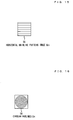
- FIG. 13 is an illustration showing an example pattern image G 11 50.
- FIG. 14 is an illustration showing an example horizontal hairline pattern G 12 54.
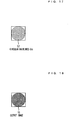
- FIG. 15 is an illustration showing an example horizontal hairline pattern G 13 55 having undergone shift processing.
- FIG. 16 is an illustration showing an example circular hairline G 14 56.
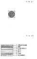
- FIG. 17 is an illustration showing an example circular hairline G 15 57 having undergone shift processing.
- FIG. 18 is an illustration showing an example output image 15.
- control section 9 of the thermal printer 1 produces from the pattern image G 11 50 a horizontal hairline pattern G 12 54 shown in FIG. 14 and composed of 3 black pixels and 19 while pixels (step 202). Further, the control section 9 of the thermal printer 1 shifts the horizontal hairline pattern G 12 54 downward by 11 pixels, to thereby produce a horizontal hairline pattern G 13 55 shown (step 203).
- the control section 9 of the thermal printer 1 performs polar coordinate conversion for the horizontal hairline patterns G 12 54 and G 13 55, to thereby produce circular hairlines G 14 56 and G 15 57 shown in FIGS. 16 and 17 , respectively (step 204).
- various methods such as a nearest neighbor interpolation method, a bilinear interpolation method, and a cubic interpolation method, exist as image interpolation methods for producing circular hairlines, the nearest neighbor interpolation method can reduce moiré to the greatest degree.
- control section 9 of the thermal printer 1 After production of the circular hairlines, the control section 9 of the thermal printer 1 performs heat-accumulation correction processing for the circular hairlines G 14 56 and G 15 57, to thereby produce circular hairlines G 16 and G 17 (step 205).
- the control section 9 of the thermal printer 1 ends the step of the image processing 23 and sends the circular hairlines G 16 and G 17 to the printing section 11 as final image data (step 206).
- the printing section 11 prints and outputs the circular hairlines G 16 and G 17 as an output image 15 in accordance with an instruction from the control section 9 (step 207).
- FIG. 18 shows the printed output image 15 including the circular hairlines.
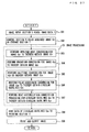
- the example printed image 1 of circular hairlines shown in FIG. 19 has a layer structure in which, after circular hairlines 61 are printed on an intermediate transfer film (not shown), a silver metallic layer 62, white layers 63 and 64 for increasing brightness, and a black layer 65 are printed thereon, and the circular hairlines 61 and the layers are transferred to a polycarbonate film 66.
- the example printed image 2 of circular hairlines shown in FIG. 21 has a layer structure in which, after smoke circular hairlines 71 are printed on an intermediate transfer film (not shown), a smoke layer 72 for suppressing glossiness, a silver metallic layer 73, white layers 74 and 75, and a black layer 76 are printed thereon, and the circular hairlines 71 and the layers are transferred to a polycarbonate film 77.
- a thermal recording apparatus or the like which reduces effects of heat accumulated in a thermal head and prints highly fine hairline images and circular hairlines by a low resolution.
- a horizontal hairline pattern is formed after the pattern definition; the shift processing is performed for the horizontal hairline pattern, whereby another horizontal hairline pattern is produced; the two horizontal hairline patterns are subjected to the polar coordinate conversion and the heat-accumulation correction processing; and two circular hairline images are printed in a superimposed state.
- the present embodiment may be modified such that the polar coordinate conversion and the heat-accumulation correction processing are performed for a single horizontal hairline pattern formed from the pattern definition, and circular hairlines are printed.
- the structure and the processing details of the thermal printer 1 are generally the same as those in the first embodiment shown in FIGS. 1 and 2 .
- the flow of the image processing 23 of the second embodiment is partially changed to produce circular hairlines by performing polar coordinate conversion for a hairline image obtained from the input image 3 through CMYK/RGB-gray conversion, gradation conversion, and halftone conversion.
- control section 9 of the thermal printer 1 executes the image processing 23. That is, the control section 9 first converts the CMYK data or RGB data of the image G 21 to gray data in accordance with the resolution of the thermal printer 1 to thereby produce an image G 22 (step 303), and stores it in the image memory 27 of the storage section 7.
- the control section 9 of the thermal printer 1 performs the gradation conversion; i.e., converts the gradation of the image G 22 to thereby produce an image G 23 (step 304), and stores it in the image memory 27 of the storage section 7.
- control section 9 performs gradation conversion of about 65% when the resolution of the thermal printer 1 is 600 dpi (dots per inch). As shown in FIGS. 5, 6 , and 7 , an output image formed through the 65% gradation conversion provides hairlines thinner and finer than those provided by an output image formed through 100% gradation conversion and those provided by an output image formed through 80% gradation conversion.
- the control section 9 of the thermal printer 1 then performs polar coordinate conversion for the image G 24 obtained through the halftone processing, to thereby produce circular hairlines G 25 (step 306).
- control section 9 of the thermal printer 1 After the production of circular hairlines, the control section 9 of the thermal printer 1 performs heat-accumulation correction processing for the circular hairlines G 25 , to thereby produce circular hairlines G 26 (step 307).
- the control section 9 of the thermal printer 1 ends the step of the image processing 23 and sends the circular hairlines G 26 to the printing section 11 as final image data (step 308).
- the printing section 11 prints and outputs the circular hairlines G 26 as an output image 15 in accordance with an instruction from the control section 9 (step 309).
- polar coordinate conversion is performed for a hairline image obtained from the input image 3 through CMYK/RGB-gray conversion, gradation conversion, and halftone conversion, whereby fine circular hairlines are produced.
Landscapes
- Electronic Switches (AREA)
- Record Information Processing For Printing (AREA)
- Editing Of Facsimile Originals (AREA)
Abstract
Description
- The present invention relates to a thermal recording apparatus or the like which reduces effects of heat accumulated in a thermal head and prints highly fine hairline images and circular hairlines by a low resolution.
- A thermal printer is an apparatus which heats the back of an ink ribbon superimposed on a recording paper by means of a thermal head in order to thermally transfer the ink of the ink ribbon onto the recording paper, to thereby print an image on the paper. The ink ribbon is a thermal transfer sheet including a layer of thermally meltable color ink, and the recording paper is an image-receiving sheet such as a sheet of paper or a plastic sheet.
- The thermal head is a composed of a plurality of heat-generating resistors formed on a substrate in a row. The thermal printer includes a plurality of ink ribbons corresponding to a plurality of colors. The inks of the ink ribbons of the plurality of colors are transferred in a superimposed state onto the recording paper at the same position, to thereby perform color printing. For example, the ink ribbons are disposed to be rotatable, and an ink ribbon to undergo thermal transfer is moved to the position of the thermal head. Further, a recording-paper feed apparatus feeds the recording paper to the position of the thermal head, which is a printing position, whereby printing is effected in a predetermined image-printing area of the recording paper.
- There have been known various methods for forming a hairline pattern, which is a pattern composed of a large number of thin lines (hairlines) extending along a specific direction. A method for consistently obtaining a clear hairline pattern has been known (see, for example, Patent Document 1). In this method, hairlines and hairline gaps are arranged on a drawing line of interest; a determination is made as to whether the hairline gaps arranged on the drawing line of interest are adjacent to the hairline gaps of a determined drawing line on which hairlines and hairline gaps have already been arranged; the drawing line of interest is treated as a determined drawing line only when none of the hairline gaps of the drawing line of interest is located adjacent to the hairline gaps of the determined drawing line; and the generation and arrangement of hairlines and hairline gaps for the drawing line of interest are performed once more when any of the hairline gaps of the drawing line of interest is located adjacent to the hairline gaps of the determined drawing line.
- There have been known various methods for forming a circular hairline. However, when a fine circular hairline is formed, a moiré, which is a periodic striped pattern, is generated.
There has been known a method for preventing periodic image disturbances, such as moiré and pitch variation, from being emphasized when a plurality of colors are superimposed (see, for example, Patent Document 2). The method is used in an image forming apparatus which forms a color image by repeating an image forming process including a step of applying an oscillating voltage to an electrifier so as to charge an image bearing body. According to the method, the frequency of the oscillating voltage applied to the electrifier is shifted each time the image forming process is repeated, whereby the periodic image disturbances are prevented from being emphasized. - Patent Document 1: Japanese Patent Application Laid-Open (kokai) No.
2002-221781
Patent Document 2: Japanese Patent Application Laid-Open (kokai) No.H6-202445 - However, the above-described first method requires complicated calculation for formation of hairlines.
Further, the above-described second method is peculiar to an image forming apparatus which forms a color image, in a transfer scheme or a direct scheme, by repeating an image forming process including a step (primary charging) of uniformly charging an image bearing body such as a photosensitive body or a dielectric body. Therefore, the second method cannot be applied to a thermal recording apparatus or the like. - The present invention has been accomplished in view of such problems, and an object of the present invention is to provide a thermal recording apparatus or the like which reduces effects of heat accumulated in a thermal head and prints highly fine hairline images and circular hairlines by a low resolution.
- A first invention for achieving the above-described object is a printed matter obtained by performing shift processing for second image data, which are obtained from first image data through gradation conversion and halftone conversion, to thereby produce third image data; performing rotation processing for said third image data to thereby produce fourth image data; performing heat-accumulation correction processing for said third image data and said fourth image data to thereby produce fifth image data and sixth image data; and printing the fifth image data and the sixth image data on an object to be printed by a thermal recording apparatus including a thermal head.
- An original image which is obtained from a read image through CMYK/RGB-gray conversion, gradation conversion, and halftone conversion, is shifted rightward and rotated by 180 degrees to thereby obtain a second image; and the original image and the second image are subjected to the heat-accumulation correction processing and are printed such that the original image and the second image are superimposed on each other. Thus, finer hairlines can be printed at a low resolution.
- A second invention is a thermal recording apparatus comprising means for performing shift processing for second image data, which are obtained from first image data through gradation conversion and halftone conversion, to thereby produce third image data; means for performing rotation processing for said third image data to thereby produce fourth image data; means for performing heat-accumulation correction processing for said third image data and said fourth image data to thereby produce fifth image data and sixth image data; and means for printing the fifth image data and the sixth image data on an object to be printed.
- A third invention is an image forming method comprising the steps of performing shift processing for second image data, which are obtained from first image data through gradation conversion and halftone conversion, to thereby produce third image data; performing rotation processing for said third image data to thereby produce fourth image data; performing heat-accumulation correction processing for said third image data and said fourth image data to thereby produce fifth image data and sixth image data; and printing the fifth image data and the sixth image data on an object to be printed by a thermal recording apparatus including a thermal head.
- A fourth invention is a printed matter obtained by producing first image data for forming a pattern; producing, from said first image data, second image data for forming a second pattern; performing shift processing for said second image data to thereby produce third image data; performing polar coordinate conversion for said second image data and said third image data to thereby produce fourth image data and fifth image data; performing heat-accumulation correction processing for said fourth image data and said fifth image data to thereby produce sixth image data and seventh image data; and printing said sixth image data and said seventh image data on an object to be printed by a thermal recording apparatus including a thermal head.
- A horizontal hairline pattern is produced by performing pattern definition, and another horizontal hairline pattern is produced by shifting the horizontal hairline pattern downward. Two circular hairlines are produced from these horizontal hairline patterns through polar coordinate conversion and combined together, whereby moiré can be reduced, and finer circular hairlines are produced.
- A fifth invention is a thermal recording apparatus comprising means for producing first image data for forming a pattern; means producing, from said first image data, second image data for forming a second pattern; means for performing shift processing for said second image data to thereby produce third image data; means for performing polar coordinate conversion for said second image data and said third image data to thereby produce fourth image data and fifth image data; means for performing heat-accumulation correction processing for said fourth image data and said fifth image data to thereby produce sixth image data and seventh image data; and means for printing said sixth image data and said seventh image data on an object to be printed.
- A sixth invention is an image forming method comprising the steps of producing first image data for forming a pattern; producing, from said first image data, second image data for forming a second pattern; performing shift processing for said second image data to thereby produce third image data; performing polar coordinate conversion for said second image data and said third image data to thereby produce fourth image data and fifth image data; performing heat-accumulation correction processing for said fourth image data and said fifth image data to thereby produce sixth image data and seventh image data; and printing said sixth image data and said seventh image data on an object to be printed by a thermal recording apparatus including a thermal head.
- A seventh invention is a printed matter obtained by producing first image data for forming a pattern; producing, from said first image data, second image data for forming a second pattern; performing polar coordinate conversion for said second image data to thereby produce third image data; performing heat-accumulation correction processing for said third image data to thereby produce fourth image data; and printing said fourth image data on an object to be printed by a thermal recording apparatus including a thermal head.
- An eighth invention is a thermal recording apparatus comprising means for producing first image data for forming a pattern; means for producing, from said first image data, second image data for forming a second pattern; means for performing polar coordinate conversion for said second image data to thereby produce third image data; means for performing heat-accumulation correction processing for said third image data to thereby produce fourth image data; and means for printing said fourth image data on an object to be printed.
- A ninth invention is an image forming method comprising the steps of producing first image data for forming a pattern; producing, from said first image data, second image data for forming a second pattern; performing polar coordinate conversion for said second image data to thereby produce third image data; performing heat-accumulation correction processing for said third image data to thereby produce fourth image data; and printing said fourth image data on an object to be printed by a thermal recording apparatus including a thermal head.
- A tenth invention is a printed matter obtained by performing polar coordinate conversion for second image data, which are obtained from first image data through gradation conversion and halftone conversion, to thereby produce third image data; performing heat-accumulation correction processing for said third image data to thereby produce fourth image data; and printing said fourth image data on an object to be printed by a thermal recording apparatus including a thermal head.
- An eleventh invention is a thermal recording apparatus comprising means for performing polar coordinate conversion for second image data, which are obtained from first image data through gradation conversion and halftone conversion, to thereby produce third image data; means for performing heat-accumulation correction processing for said third image data to thereby produce fourth image data; and means for printing said fourth image data on an object to be printed.
- A twelfth invention is an image forming method comprising the steps of performing polar coordinate conversion for second image data, which are obtained from first image data through gradation conversion and halftone conversion, to thereby produce third image data; performing heat-accumulation correction processing for said third image data to thereby produce fourth image data; and printing said fourth image data on an object to be printed by a thermal recording apparatus including a thermal head.
- According to the present invention, it is possible to provide a thermal recording apparatus or the like which reduces effects of heat accumulated in a thermal head and prints highly fine hairline images and circular hairlines by a low resolution.
-
- [
FIG. 1 ] Diagram showing the configuration of athermal printer 1. - [
FIG. 2 ] Diagram showing the relation between the configuration of thethermal printer 1 and the details of processing. - [
FIG. 3 ] Diagram showing the details of astorage section 7 of thethermal printer 1. - [
FIG. 4 ] Flowchart showing operation ofimage processing 23 according to a first embodiment. - [
FIG. 5 ] Illustration showing an example output image in the case of gradation conversion of 100%. - [
FIG. 6 ] Illustration showing an example output image in the case of gradation conversion of 80%. - [
FIG. 7 ] Illustration showing an example output image in the case of gradation conversion of 65%. - [
FIG. 8 ] Illustration used for explaining a method of generating an image G5 31-5 through lateral shift. - [
FIG. 9 ] Illustration showing an example halftone-converted image of hairlines. - [
FIG. 10 ] Illustration showing an example halftone-converted image of hairlines having undergone shift processing. - [
FIG. 11 ] Illustration showing an example halftone-converted image of hairlines having undergone shift processing and rotation processing. - [
FIG. 12 ] Flowchart showing the flow of processing of theimage processing 23 according to the first embodiment. - [
FIG. 13 ] Illustration showing an examplepattern image G 11 50. - [
FIG. 14 ] Illustration showing an example horizontalhairline pattern G 12 54. - [
FIG. 15 ] Illustration showing an example horizontalhairline pattern G 13 55 having undergone shift processing. - [
FIG. 16 ] Illustration showing an examplecircular hairline G 14 56. - [
FIG. 17 ] Illustration showing an examplecircular hairline G 15 57 having undergone shift processing. - [
FIG. 18 ] Illustration showing anexample output image 15. - [
FIG. 19 ] Illustration showing an example printedimage 1 of circular hairlines. - [
FIG. 20 ] Illustration showing the layer structure of the example printedimage 1 of circular hairlines. - [
FIG. 21 ] Illustration showing an example printed image 2 of circular hairlines. - [
FIG. 22 ] Illustration showing the layer structure of the example printed image 2 of circular hairlines. - [
FIG. 23 ] Illustration showing an example printedimage 3 of circular hairlines. - [
FIG. 24 ] Illustration showing the layer structure of the example printedimage 3 of circular hairlines. - [
FIG. 25 ] Illustration showing an example printed image 4 of circular hairlines. - [
FIG. 26 ] Illustration showing the layer structure of the example printed image 4 of circular hairlines. - [
FIG. 27 ] Flowchart showing the flow of processing of theimage processing 23 according to a second embodiment. -
- 1 ···
- thermal printer
- 3 ···
- image data
- 5 ···
- image input section
- 7 ···
- storage section
- 9 ···
- control section
- 11 ···
- printing section
- 13 ···
- bus
- 15 ···
- output images
- 21 ···
- image reading
- 23 ···
- image processing
- 25 ···
- image printing
- 27 ···
- image memory
- 29 ···
- processing parameter
- A first preferred embodiment of a thermal recording apparatus, etc. according to the present invention will next be described in detail with reference to the attached drawings.
- First, the configuration of the thermal recording apparatus (thermal printer 1) of the embodiment of the present invention will be described with reference to
FIG. 1 .
FIG. 1 is a diagram showing the configuration of thethermal printer 1. - As shown in
FIG. 1 , thethermal printer 1 is an apparatus which heats the back of an ink ribbon (not shown) superimposed on a recording paper (not shown) by means of a thermal head (not shown) in order to thermally transfer the ink of the ink ribbon onto the recording paper, to thereby print an image on the paper. Thethermal printer 1 includes animage input section 5, astorage section 7, acontrol section 9, aprinting section 11, etc. which are connected together via abus 13. -
Image data 3 to be printed are input to theimage input section 5. Thestorage section 7 stores theinput image data 3, data to be temporarily stored in the course of calculation, processed image data, parameters for image processing, etc. Thecontrol section 9 is composed of a CPU (central processing unit) which executes programs, and memory such as ROM (read only memory), RAM (random access memory), etc. for storing program instruction, data, etc. Thecontrol section 9 instructs theimage input section 5 to read theimage data 3 or process theimage data 3, sends processed image data to theprinting section 11, and instructs theprinting section 11 to print the image data. - Although not illustrated, the
printing section 11 is composed of a thermal head including a plurality of heat-generating resistors formed in a row on a substrate; a thermal head drive section; etc. Upon receipt of image data to be printed and an instruction from thecontrol section 9, theprinting section 11 applies to the thermal head energy corresponding to each pixel value. Thus, ink at the energy-applied portion melts and adheres to recording paper, whereby anoutput image 15 is output. The greater the pixel value, the greater the image recording density; and the smaller the pixel value, the lower the image recording density.
Notably, theprinting section 11 includes four types of ink ribbons of cyan C, magenta M, yellow Y, and black K. The inks of these colors are transferred in a superimposed state so as to perform color printing. -
FIG. 2 is a diagram showing the relation between the configuration of thethermal printer 1 ofFIG. 1 and the details of processing.
Theimage input section 5 performs image reading 21 so as to read theimage data 3. Theimage input section 5 stores the read image data intoimage memory 27 of thestorage section 7, and simultaneously sends the image data to thecontrol section 9. Thecontrol section 9 performsimage processing 23 on theimage data 3. - The
memory section 7 is composed of theimage memory 27 for storing image data to undergo image processing, and theprocessing parameter memory 29 for storing parameters used when the image processing is performed. Further, although not illustrated, thestorage section 7 further stores a control program, and control parameters of theprinting section 11 such as the thermal head. - Image data acquired by the
thermal printer 1 and image data calculated in the course of theimage processing 23 are registered in theimage memory 27.
Notably, the original image and image data obtained in the course of calculation, excluding the final image data, are not necessarily required to be left in theimage memory 27. - The
processing parameter memory 29 of thestorage section 7 stores parameters which are used by theimage processing 23 for pattern formation, shift processing, polar coordinate conversion, heat-accumulation correction processing. - The
control section 9 performs theimage processing 23.
Theimage processing 23 includes various types of processing such as CMYK/RGB-gray conversion processing, gradation conversion processing, halftone conversion processing, pattern definition, horizontal hairline pattern formation, shift processing, rotation processing, polar coordinate conversion, and heat-accumulation correction processing. Theimage processing 23 performs image processing for the image data stored in theimage memory 27 of thestorage section 7 while using respective processing parameters stored in theprocessing parameter memory 29 to thereby obtain final image data. Image data produced in the course of the processing are stored in theimage memory 27 of thestorage section 7. Thecontrol section 9 sends the finally obtained image data to theprinting section 11, which performsimage printing 25. -
FIG. 3 is a diagram showing the details of thestorage section 7 of thethermal printer 1. Thememory section 7 is composed of theimage memory 27 for storing image data to undergo image processing, and theprocessing parameter memory 29 for storing parameters used when the image processing is performed. Further, although not illustrated, thestorage section 7 further stores a control program, and control parameters of theprinting section 11 such as the thermal head. - The
image data 3, which represent the original image acquired by thethermal printer 1, are registered in theimage memory 27, as an image G1 31-1. Images G2 31-2, G3 31-3, G4 31-4, G5 31-5, G6 31-6, G7 31-7, G8 31-8, etc. are registered as image data calculated in the course of theimage processing 23. - Notably, the image G1 31-1, which is the original image, and image data calculated in the course of calculation, excluding the images G7 31-7 and G8 31-8, which serve as final image data, are not required to be left in the
image memory 27. - The
processing parameter memory 29 of thestorage section 7 stores a CMYK/RGB-gray conversion parameter 33, agradation conversion parameter 35, ahalftone conversion parameter 37, ashift processing parameter 39, arotation processing parameter 41, a heat-accumulationcorrection processing parameter 43, etc., which are used by theimage processing 23. - Next, the flow of image processing in the
thermal printer 1 will be described.FIG. 4 is a flowchart showing operation performed by theimage processing 23 according to the first embodiment.FIG. 5 is an illustration showing an example output image in the case of gradation conversion of 100%.FIG. 6 is an illustration showing an example output image in the case of gradation conversion of 80%.FIG. 7 is an illustration showing an example output image in the case of gradation conversion of 65%.FIG. 8 is an illustration used for explaining a method of generating the image G5 31-5 through lateral shift.FIG. 9 is an illustration showing an example halftone-converted image of hairlines.FIG. 10 is an illustration showing an example halftone-converted image of hairlines having undergone the shift processing.FIG. 11 is an illustration showing an example halftone-converted image of hairlines having undergone the shift processing and the rotation processing. - The
image input section 5 of the thermal printer reads the image data 3 (step 101); and thecontrol section 9 holds the acquired image G1 31-1 in theimage memory 27 of the storage section 7 (step 102). - Next, the
control section 9 of thethermal printer 1 executes theimage processing 23. That is, thecontrol section 9 first converts the CMYK data or RGB data of the image G1 31-1 to gray data in accordance with the resolution of thethermal printer 1 to thereby produce the image G2 31-2 (step 103), and stores it in theimage memory 27 of thestorage section 7. - The
control section 9 of thethermal printer 1 performs the gradation conversion; i.e., converts the gradation of the image G2 31-2 to thereby produce the image G3 31-3 (step 104), and stores it in theimage memory 27 of thestorage section 7. - In order to form thin and finer hairlines, the
control section 9 performs gradation conversion of about 65% when the resolution of thethermal printer 1 is 600 dpi (dots per inch).
As shown inFIGS. 5, 6 , and7 , an output image formed through the 65% gradation conversion provides hairlines thinner and finer than those provided by an output image formed through 100% gradation conversion and those provided by an output image formed through 80% gradation conversion. - The
control section 9 of thethermal printer 1 performs halftone processing for the image G3 31-3 obtained through gradation conversion, to thereby produce the image G4 31-4 (step 105).
Here, it is assumed that image data express the C, M, Y, K components with the same angle, for example, image data are of a line screen type (intersection angle: 90°).
The matrix size of each halftone dot varies depending on the resolution of thethermal printer 1 and the number of lines. For example, when the resolution of thethermal printer 1 is 600 dpi, the matrix size is 10 x 10 pixels for the case where the number of lines is 60 lpi (lines per inch), 8 x 8 pixels for the case where the number of lines is 75 lpi, 6 x 6 pixels for the case where the number of lines is 100 lpi, and 5 x 5 pixels for the case where the number of lines is 120 lpi. - The
control section 9 of thethermal printer 1 then performs shift processing for the image G4 31-4 obtained through the halftone processing, to thereby produce the image G5 31-5 (step 106).
As shown inFIG. 8 , the direction of the shift processing is the rightward direction only, and the number of pixels L1 by which the image is shifted varies depending on the number of lines of the halftone dot.
For example, when the resolution of thethermal printer 1 is 600 dpi, L1 is three pixels for the case where the number of lines of the halftone dot is 100 lpi, L1 is four pixels for the case where the number of lines is 75 lpi, L1 is five pixels for the case where the number of lines is 60 lpi, and L1 is two pixels for the case where the number of lines is 120 lpi. - After the shift processing, the
control section 9 of thethermal printer 1 performs rotation processing for the image G5 31-5, to thereby produce the image G6 31-6 (step 107).
In the rotation processing, thecontrol section 9 rotates the image G5 31-5 by 180 degrees. - The
control section 9 of thethermal printer 1 performs heat-accumulation correction processing for the images G4 31-4 and G6 31-6, to thereby produce the images G7 31-7 and G8 31-8 (step 108). - The
control section 9 of thethermal printer 1 ends the step of theimage processing 23 and sends the images G7 31-7 and G8 31-8 to theprinting section 11 as final image data (step 109).
In accordance with an instruction from thecontrol section 9, theprinting section 11 prints and outputs the images G7 31-7 and G8 31-8 as an output image 15 (step 110). - Since a first image and a second image obtained by shifting and rotating the first image are printed in a superimposed state, a halftone-converted image of hairlines can be made finer.
By superimposing, on a hairline halftone-converted image shown inFIG. 9 , an image obtaining by shifting the hairline halftone-converted image, a finer halftone-converted image of hairlines is produced as shown inFIG. 10 . Further, by superimposing, on the hairline halftone-converted image shown inFIG. 9 , an image obtaining by shifting and rotating the hairline halftone-converted image, a halftone-converted image of hairlines which is finer and more random is produced as shown inFIG. 11 . - As described above, according to the present embodiment, there can be provided a thermal recording apparatus or the like which reduces effects of heat accumulated in a thermal head and prints highly fine hairline images and circular hairlines by a low resolution.
- Next, a second preferred embodiment of the thermal recording apparatus of the present invention will be described.
- In the second embodiment, the structure and the processing details of the
thermal printer 1 are generally the same as those in the first embodiment shown inFIGS. 1 and 2 .
In the second embodiment, a horizontal hairline pattern is formed after the pattern definition; the shift processing is performed for the horizontal hairline pattern, whereby another horizontal hairline pattern is produced; the two horizontal hairline patterns are subjected to the polar coordinate conversion and the heat-accumulation correction processing; and two circular hairline images are printed in a superimposed state. - In the following, the flow of processing of forming circular hairlines through pattern definition will be described.
FIG. 12 is a flowchart showing the flow of processing of theimage processing 23 according to the second embodiment.FIG. 13 is an illustration showing an examplepattern image G 11 50.FIG. 14 is an illustration showing an example horizontalhairline pattern G 12 54.FIG. 15 is an illustration showing an example horizontalhairline pattern G 13 55 having undergone shift processing.FIG. 16 is an illustration showing an examplecircular hairline G 14 56.FIG. 17 is an illustration showing an examplecircular hairline G 15 57 having undergone shift processing.FIG. 18 is an illustration showing anexample output image 15. - The
control section 9 of thethermal printer 1 performs theimage processing 23 so as to perform pattern definition of circular hairlines and produce a pattern image G11 50 (step 201).
As shown inFIG. 13 , thepattern image G 11 50 is composed ofblack pixels 51 andwhite pixels 53. By changing the numbers of theblack pixels 51 and thewhite pixels 53, circular hairlines of various widths can be generated. In the present embodiment, the number of theblack pixels 51 is 3, and the number of thewhite pixels 53 is 19. - Next, the
control section 9 of thethermal printer 1 produces from the pattern image G11 50 a horizontalhairline pattern G 12 54 shown inFIG. 14 and composed of 3 black pixels and 19 while pixels (step 202).
Further, thecontrol section 9 of thethermal printer 1 shifts the horizontalhairline pattern G 12 54 downward by 11 pixels, to thereby produce a horizontalhairline pattern G 13 55 shown (step 203). - The
control section 9 of thethermal printer 1 performs polar coordinate conversion for the horizontalhairline patterns G 12 54 andG 13 55, to thereby producecircular hairlines G 14 56 andG 15 57 shown inFIGS. 16 and17 , respectively (step 204).
Although various methods, such as a nearest neighbor interpolation method, a bilinear interpolation method, and a cubic interpolation method, exist as image interpolation methods for producing circular hairlines, the nearest neighbor interpolation method can reduce moiré to the greatest degree. - After production of the circular hairlines, the
control section 9 of thethermal printer 1 performs heat-accumulation correction processing for thecircular hairlines G 14 56 andG 15 57, to thereby produce circular hairlines G16 and G17 (step 205). - The
control section 9 of thethermal printer 1 ends the step of theimage processing 23 and sends the circular hairlines G16 and G17 to theprinting section 11 as final image data (step 206).
Theprinting section 11 prints and outputs the circular hairlines G16 and G17 as anoutput image 15 in accordance with an instruction from the control section 9 (step 207).
FIG. 18 shows the printedoutput image 15 including the circular hairlines. - Since a first image and a second image obtained by shifting the first image are printed in a superimposed state, moiré is reduced, and finer circular hairlines can be formed.
- Next, examples of the printed circular hairlines will be described with reference to
FIGS. 19, 20 ,21, 22 ,23, 24 ,25, and 26 .
FIG. 19 is an illustration showing an example printedimage 1 of circular hairlines.FIG. 20 is an illustration showing the layer structure of the example printedimage 1 of circular hairlines.FIG. 21 is an illustration showing an example printed image 2 of circular hairlines.FIG. 22 is an illustration showing the layer structure of the example printed image 2 of circular hairlines.FIG. 23 is an illustration showing an example printedimage 3 of circular hairlines.FIG. 24 is an illustration showing the layer structure of the example printedimage 3 of circular hairlines.FIG. 25 is an illustration showing an example printed image 4 of circular hairlines.FIG. 26 is an illustration showing the layer structure of the example printed image 4 of circular hairlines. - As shown in
FIG. 20 , the example printedimage 1 of circular hairlines shown inFIG. 19 has a layer structure in which, aftercircular hairlines 61 are printed on an intermediate transfer film (not shown), a silver metallic layer 62,white layers 63 and 64 for increasing brightness, and a black layer 65 are printed thereon, and thecircular hairlines 61 and the layers are transferred to a polycarbonate film 66. - As shown in
FIG. 22 , the example printed image 2 of circular hairlines shown inFIG. 21 has a layer structure in which, after smokecircular hairlines 71 are printed on an intermediate transfer film (not shown), asmoke layer 72 for suppressing glossiness, a silver metallic layer 73,white layers black layer 76 are printed thereon, and thecircular hairlines 71 and the layers are transferred to a polycarbonate film 77. - As shown in
FIG. 24 , the example printedimage 3 of circular hairlines shown inFIG. 23 has a layer structure in which, in order to emphasize the 3D impression, blackcircular hairlines 81 are printed on a polycarbonate film 82, and a silver metallic layer 83,white layers 84 and 85, and a black layer 86 are printed thereon. - As shown in
FIG. 26 , the example printed image 4 of circular hairlines shown inFIG. 25 has a layer structure in which, after smokecircular hairlines 91 are printed on an intermediate transfer film (not shown), a circular gradation layer 92 of cyan, a silver metallic layer 93,white layers 94 and 95, and a black layer 96 are printed thereon, and thecircular hairlines 91 and the layers are transferred to a polycarbonate film 97. Positioning of thecircular hairlines 91 and the circular gradation layer 92 can be performed easily. - As described above, according to the present embodiment, there can be provided a thermal recording apparatus or the like which reduces effects of heat accumulated in a thermal head and prints highly fine hairline images and circular hairlines by a low resolution.
- In the present embodiment, a horizontal hairline pattern is formed after the pattern definition; the shift processing is performed for the horizontal hairline pattern, whereby another horizontal hairline pattern is produced; the two horizontal hairline patterns are subjected to the polar coordinate conversion and the heat-accumulation correction processing; and two circular hairline images are printed in a superimposed state. However, the present embodiment may be modified such that the polar coordinate conversion and the heat-accumulation correction processing are performed for a single horizontal hairline pattern formed from the pattern definition, and circular hairlines are printed.
- Further, circular hairlines having various widths can be readily printed by changing the numbers of black and white pixels used in the pattern definition.
- Next, a third preferred embodiment of the thermal recording apparatus of the present invention will be described.
- In the third embodiment, the structure and the processing details of the
thermal printer 1 are generally the same as those in the first embodiment shown inFIGS. 1 and 2 .
In the third embodiment, the flow of theimage processing 23 of the second embodiment is partially changed to produce circular hairlines by performing polar coordinate conversion for a hairline image obtained from theinput image 3 through CMYK/RGB-gray conversion, gradation conversion, and halftone conversion. - In the following, the flow of processing for producing circular hairlines from an input image will be described.
FIG. 27 is a flowchart showing the flow of processing of theimage processing 23 according to the third embodiment. - The
image input section 5 of the thermal printer reads the image data 3 (step 301); and thecontrol section 9 holds an acquired image G21 in theimage memory 27 of the storage section 7 (step 302). - Next, the
control section 9 of thethermal printer 1 executes theimage processing 23. That is, thecontrol section 9 first converts the CMYK data or RGB data of the image G21 to gray data in accordance with the resolution of thethermal printer 1 to thereby produce an image G22 (step 303), and stores it in theimage memory 27 of thestorage section 7. - The
control section 9 of thethermal printer 1 performs the gradation conversion; i.e., converts the gradation of the image G22 to thereby produce an image G23 (step 304), and stores it in theimage memory 27 of thestorage section 7. - In order to form thin and finer hairlines, the
control section 9 performs gradation conversion of about 65% when the resolution of thethermal printer 1 is 600 dpi (dots per inch).
As shown inFIGS. 5, 6 , and7 , an output image formed through the 65% gradation conversion provides hairlines thinner and finer than those provided by an output image formed through 100% gradation conversion and those provided by an output image formed through 80% gradation conversion. - The
control section 9 of thethermal printer 1 performs halftone processing for the image G23 obtained through gradation conversion, to thereby produce an image G24 (step 305).
Here, it is assumed that image data express the C, M, Y, K components with the same angle, for example, image data are of a line screen type (intersection angle: 90°).
The matrix size of each halftone dot varies depending on the resolution of thethermal printer 1 and the number of lines. For example, when the resolution of thethermal printer 1 is 600 dpi, the matrix size is 10 x 10 pixels for the case where the number of lines is 60 lpi (lines per inch), 8 x 8 pixels for the case where the number of lines is 75 lpi, 6 x 6 pixels for the case where the number of lines is 100 lpi, and 5 x 5 pixels for the case where the number of lines is 120 lpi. - The
control section 9 of thethermal printer 1 then performs polar coordinate conversion for the image G24 obtained through the halftone processing, to thereby produce circular hairlines G25 (step 306). - After the production of circular hairlines, the
control section 9 of thethermal printer 1 performs heat-accumulation correction processing for the circular hairlines G25, to thereby produce circular hairlines G26 (step 307). - The
control section 9 of thethermal printer 1 ends the step of theimage processing 23 and sends the circular hairlines G26 to theprinting section 11 as final image data (step 308).
Theprinting section 11 prints and outputs the circular hairlines G26 as anoutput image 15 in accordance with an instruction from the control section 9 (step 309). - In the above-described third preferred embodiment, polar coordinate conversion is performed for a hairline image obtained from the
input image 3 through CMYK/RGB-gray conversion, gradation conversion, and halftone conversion, whereby fine circular hairlines are produced. - Preferred embodiments of the thermal recording apparatus according to the present invention have been described with reference to the accompanying drawings. However, the present invention is not limited to the above-described embodiments. It is clear that a person with ordinary skill in the art can easily conceive various modifications and changes within the technical idea described in the claims, and it is contemplated that such modifications and changes naturally fall within the technical scope of the present invention.
Claims (27)
- A printed matter obtained by:performing shift processing for second image data, which are obtained from first image data through gradation conversion and halftone conversion, to thereby produce third image data;performing rotation processing for said third image data to thereby produce fourth image data;performing heat-accumulation correction processing for said third image data and said fourth image data to thereby produce fifth image data and sixth image data; andprinting the fifth image data and the sixth image data on an object to be printed by a thermal recording apparatus including a thermal head.
- A printed matter according to claim 1, wherein said rotation processing rotates said third image data by 180 degrees.
- A thermal recording apparatus comprising:means for performing shift processing for second image data, which are obtained from first image data through gradation conversion and halftone conversion, to thereby produce third image data;means for performing rotation processing for said third image data to thereby produce fourth image data;means for performing heat-accumulation correction processing for said third image data and said fourth image data to thereby produce fifth image data and sixth image data; andmeans for printing the fifth image data and the sixth image data on an object to be printed.
- A thermal recording apparatus according to claim 3, wherein said rotation processing rotates said third image data by 180 degrees.
- An image forming method comprising the steps of:performing shift processing for second image data, which are obtained from first image data through gradation conversion and halftone conversion, to thereby produce third image data;performing rotation processing for said third image data to thereby produce fourth image data;performing heat-accumulation correction processing for said third image data and said fourth image data to thereby produce fifth image data and sixth image data; andprinting the fifth image data and the sixth image data on an object to be printed by a thermal recording apparatus including a thermal head.
- An image forming method according to claim 5, wherein said rotation processing rotates said third image data by 180 degrees.
- A printed matter obtained by:producing first image data for forming a pattern;producing, from said first image data, second image data for forming a second pattern;performing shift processing for said second image data to thereby produce third image data;performing polar coordinate conversion for said second image data and said third image data to thereby produce fourth image data and fifth image data;performing heat-accumulation correction processing for said fourth image data and said fifth image data to thereby produce sixth image data and seventh image data; andprinting said sixth image data and said seventh image data on an object to be printed by a thermal recording apparatus including a thermal head.
- A printed matter according to claim 7, wherein a circular hairline is printed on the object to be printed.
- A printed matter according to claim 7, wherein a line width can be changed by changing said first pattern.
- A thermal recording apparatus comprising:means for producing first image data for forming a pattern;means for producing, from said first image data, second image data for forming a second pattern;means for performing shift processing for said second image data to thereby produce third image data;means for performing polar coordinate conversion for said second image data and said third image data to thereby produce fourth image data and fifth image data;means for performing heat-accumulation correction processing for said fourth image data and said fifth image data to thereby produce sixth image data and seventh image data; andmeans for printing said sixth image data and said seventh image data on an object to be printed.
- A thermal recording apparatus according to claim 10, wherein a circular hairline is printed on the object to be printed.
- A thermal recording apparatus according to claim 10, wherein a width of said circular hairline can be changed by changing said first pattern.
- An image forming method comprising the steps of producing first image data for forming a pattern;
producing, from said first image data, second image data for forming a second pattern;
performing shift processing for said second image data to thereby produce third image data;
performing polar coordinate conversion for said second image data and said third image data to thereby produce fourth image data and fifth image data;
performing heat-accumulation correction processing for said fourth image data and said fifth image data to thereby produce sixth image data and seventh image data; and
printing said sixth image data and said seventh image data on an object to be printed by a thermal recording apparatus including a thermal head. - An image forming method according to claim 13, wherein a circular hairline is printed on the object to be printed.
- An image forming method according to claim 13, wherein a width of said circular hairline can be changed by changing said first pattern.
- A printed matter obtained by:producing first image data for forming a pattern;producing, from said first image data, second image data for forming a second pattern;performing polar coordinate conversion for said second image data to thereby produce third image data;performing heat-accumulation correction processing for said third image data to thereby produce fourth image data; andprinting said fourth image data on an object to be printed by a thermal recording apparatus including a thermal head.
- A printed matter according to claim 16, wherein a circular hairline is printed on the object to be printed.
- A printed matter according to claim 16, wherein a line width can be changed by changing said first pattern.
- A thermal recording apparatus comprising:means for producing first image data for forming a pattern;means for producing, from said first image data, second image data for forming a second pattern;means for performing polar coordinate conversion for said second image data to thereby produce third image data;means for performing heat-accumulation correction processing for said third image data to thereby produce fourth image data; andmeans for printing said fourth image data on an object to be printed.
- A thermal recording apparatus according to claim 19, wherein a circular hairline is printed on the object to be printed.
- A thermal recording apparatus according to claim 19, wherein a width of said circular hairline can be changed by changing said first pattern.
- An image forming method comprising the steps of:producing first image data for forming a pattern;producing, from said first image data, second image data for forming a second pattern;performing polar coordinate conversion for said second image data to thereby produce third image data;performing heat-accumulation correction processing for said third image data to thereby produce fourth image data; andprinting said fourth image data on an object to be printed by a thermal recording apparatus including a thermal head.
- An image forming method according to claim 22, wherein a circular hairline is printed on the object to be printed.
- An image forming method according to claim 22, wherein a width of said circular hairline can be changed by changing said first pattern.
- A printed matter obtained by:performing polar coordinate conversion for second image data, which are obtained from first image data through gradation conversion and halftone conversion, to thereby produce third image data;performing heat-accumulation correction processing for said third image data to thereby produce fourth image data; andprinting said fourth image data on an object to be printed by a thermal recording apparatus including a thermal head.
- A thermal recording apparatus comprising:means for performing polar coordinate conversion for second image data, which are obtained from first image data through gradation conversion and halftone conversion, to thereby produce third image data;means for performing heat-accumulation correction processing for said third image data to thereby produce fourth image data; andmeans for printing said fourth image data on an object to be printed.
- An image forming method comprising the steps of:performing polar coordinate conversion for second image data, which are obtained from first image data through gradation conversion and halftone conversion, to thereby produce third image data;performing heat-accumulation correction processing for said third image data to thereby produce fourth image data; andprinting said fourth image data on an object to be printed by a thermal recording apparatus including a thermal head.
Priority Applications (1)
| Application Number | Priority Date | Filing Date | Title |
|---|---|---|---|
| EP10014987A EP2314455B1 (en) | 2006-03-31 | 2007-03-28 | Thermal recording device and image forming method |
Applications Claiming Priority (3)
| Application Number | Priority Date | Filing Date | Title |
|---|---|---|---|
| JP2006096544A JP4358200B2 (en) | 2006-03-31 | 2006-03-31 | Thermal recording apparatus, image forming method and printed matter |
| JP2006096523A JP4358199B2 (en) | 2006-03-31 | 2006-03-31 | Thermal recording apparatus, image forming method and printed matter |
| PCT/JP2007/056602 WO2007114147A1 (en) | 2006-03-31 | 2007-03-28 | Thermal recording device, image forming method and printed matter |
Related Child Applications (1)
| Application Number | Title | Priority Date | Filing Date |
|---|---|---|---|
| EP10014987A Division-Into EP2314455B1 (en) | 2006-03-31 | 2007-03-28 | Thermal recording device and image forming method |
Publications (4)
| Publication Number | Publication Date |
|---|---|
| EP2006114A2 EP2006114A2 (en) | 2008-12-24 |
| EP2006114A9 true EP2006114A9 (en) | 2009-07-22 |
| EP2006114A4 EP2006114A4 (en) | 2010-06-23 |
| EP2006114B1 EP2006114B1 (en) | 2014-11-26 |
Family
ID=38563416
Family Applications (2)
| Application Number | Title | Priority Date | Filing Date |
|---|---|---|---|
| EP10014987A Expired - Fee Related EP2314455B1 (en) | 2006-03-31 | 2007-03-28 | Thermal recording device and image forming method |
| EP07740040.6A Expired - Fee Related EP2006114B1 (en) | 2006-03-31 | 2007-03-28 | Thermal recording device, image forming method and printed matter |
Family Applications Before (1)
| Application Number | Title | Priority Date | Filing Date |
|---|---|---|---|
| EP10014987A Expired - Fee Related EP2314455B1 (en) | 2006-03-31 | 2007-03-28 | Thermal recording device and image forming method |
Country Status (4)
| Country | Link |
|---|---|
| US (1) | US8031374B2 (en) |
| EP (2) | EP2314455B1 (en) |
| KR (1) | KR101351828B1 (en) |
| WO (1) | WO2007114147A1 (en) |
Families Citing this family (1)
| Publication number | Priority date | Publication date | Assignee | Title |
|---|---|---|---|---|
| US9364995B2 (en) | 2013-03-15 | 2016-06-14 | Matterrise, Inc. | Three-dimensional printing and scanning system and method |
Family Cites Families (8)
| Publication number | Priority date | Publication date | Assignee | Title |
|---|---|---|---|---|
| CA1289676C (en) * | 1986-09-19 | 1991-09-24 | Shinko Electric Co., Ltd. | Thermal transfer type printer |
| JPH06202445A (en) | 1992-12-28 | 1994-07-22 | Canon Inc | Image forming device |
| JP2000135810A (en) * | 1998-08-26 | 2000-05-16 | Toppan Printing Co Ltd | Imaging apparatus, imaging method and imaging body |
| JP4666432B2 (en) | 2001-01-26 | 2011-04-06 | 大日本印刷株式会社 | Hairline pattern creation device |
| JP4688121B2 (en) * | 2001-04-04 | 2011-05-25 | 大日本印刷株式会社 | Method and apparatus for creating hairline pattern |
| JP4142276B2 (en) * | 2001-08-28 | 2008-09-03 | 富士フイルム株式会社 | Image transmission method, image server system, and program |
| JP4386779B2 (en) * | 2004-03-31 | 2009-12-16 | 大日本印刷株式会社 | Thermal storage correction device, thermal storage correction method, and thermal recording device |
| KR100772370B1 (en) * | 2004-08-14 | 2007-11-01 | 삼성전자주식회사 | Method and apparatus for adjusting alignment of image forming device |
-
2007
- 2007-03-28 EP EP10014987A patent/EP2314455B1/en not_active Expired - Fee Related
- 2007-03-28 EP EP07740040.6A patent/EP2006114B1/en not_active Expired - Fee Related
- 2007-03-28 US US12/294,280 patent/US8031374B2/en not_active Expired - Fee Related
- 2007-03-28 WO PCT/JP2007/056602 patent/WO2007114147A1/en active Application Filing
- 2007-03-28 KR KR1020087021170A patent/KR101351828B1/en active IP Right Grant
Also Published As
| Publication number | Publication date |
|---|---|
| EP2314455B1 (en) | 2012-05-23 |
| US8031374B2 (en) | 2011-10-04 |
| WO2007114147A1 (en) | 2007-10-11 |
| KR101351828B1 (en) | 2014-01-23 |
| EP2314455A1 (en) | 2011-04-27 |
| EP2006114B1 (en) | 2014-11-26 |
| US20090161166A1 (en) | 2009-06-25 |
| KR20080105051A (en) | 2008-12-03 |
| EP2006114A2 (en) | 2008-12-24 |
| EP2006114A4 (en) | 2010-06-23 |
Similar Documents
| Publication | Publication Date | Title |
|---|---|---|
| EP1734736B1 (en) | Compensation for malfunctioning jets | |
| US6293651B1 (en) | Multi-head printer | |
| EP1946932B1 (en) | Thermal recording device, image forming method, and printed object | |
| EP2314455B1 (en) | Thermal recording device and image forming method | |
| US8149462B2 (en) | Line printer | |
| JP2006159505A (en) | Image forming method, and its device | |
| US8164787B2 (en) | Thermal transfer recording device and image formation method | |
| JP4358199B2 (en) | Thermal recording apparatus, image forming method and printed matter | |
| JP2961503B2 (en) | Halftone pattern generation method | |
| EP1865705A1 (en) | Image data generation device, image data generation program, thermal transfer/recording device, and others | |
| JP4929737B2 (en) | Thermal transfer recording apparatus and thermal transfer recording method | |
| JP4358200B2 (en) | Thermal recording apparatus, image forming method and printed matter | |
| JP3200519B2 (en) | Image quality improvement method for thermal printer | |
| JP2007106122A (en) | Switching of resolution factors for direct marking printing | |
| JP3834573B2 (en) | Building board printer | |
| JP2007313815A (en) | Thermal transfer recording apparatus, image forming method, and printed matter | |
| JP5360824B2 (en) | Method and apparatus for multi-tone recording | |
| JP2007268832A (en) | Thermal recorder, method of correcting heat accumulation, and printed matter | |
| JP2007268730A (en) | Thermal recorder, image formation method and printed matter | |
| JP2004064473A (en) | Method for preparing threshold matrix and device for preparing color image data | |
| JPH10217528A (en) | Method for recording color image, color image-recording apparatus, and method for controlling recording of color image | |
| JPH08290596A (en) | Full-color recorder | |
| JP2008546351A (en) | Method and system for inter-channel clock frequency selection with periodic halftoning | |
| JP2006062084A (en) | Thermal recorder, program, and recording medium | |
| JPH0250872A (en) | Printing method of printer |
Legal Events
| Date | Code | Title | Description |
|---|---|---|---|
| PUAI | Public reference made under article 153(3) epc to a published international application that has entered the european phase |
Free format text: ORIGINAL CODE: 0009012 |
|
| PUAB | Information related to the publication of an a document modified or deleted |
Free format text: ORIGINAL CODE: 0009199EPPU |
|
| 17P | Request for examination filed |
Effective date: 20081030 |
|
| AK | Designated contracting states |
Kind code of ref document: A2 Designated state(s): DE FR GB IT |
|
| DAX | Request for extension of the european patent (deleted) | ||
| RBV | Designated contracting states (corrected) |
Designated state(s): DE FR GB IT |
|
| A4 | Supplementary search report drawn up and despatched |
Effective date: 20100527 |
|
| RIC1 | Information provided on ipc code assigned before grant |
Ipc: B41J 2/365 20060101AFI20071113BHEP Ipc: B41J 2/325 20060101ALI20100520BHEP Ipc: B41J 2/36 20060101ALI20100520BHEP |
|
| RIC1 | Information provided on ipc code assigned before grant |
Ipc: B41J 2/325 20060101ALI20130822BHEP Ipc: B41J 2/36 20060101ALI20130822BHEP Ipc: B41J 2/365 20060101AFI20130822BHEP |
|
| GRAP | Despatch of communication of intention to grant a patent |
Free format text: ORIGINAL CODE: EPIDOSNIGR1 |
|
| INTG | Intention to grant announced |
Effective date: 20140616 |
|
| GRAS | Grant fee paid |
Free format text: ORIGINAL CODE: EPIDOSNIGR3 |
|
| GRAA | (expected) grant |
Free format text: ORIGINAL CODE: 0009210 |
|
| AK | Designated contracting states |
Kind code of ref document: B1 Designated state(s): DE FR GB IT |
|
| REG | Reference to a national code |
Ref country code: GB Ref legal event code: FG4D |
|
| REG | Reference to a national code |
Ref country code: DE Ref legal event code: R096 Ref document number: 602007039425 Country of ref document: DE Effective date: 20150108 |
|
| REG | Reference to a national code |
Ref country code: DE Ref legal event code: R097 Ref document number: 602007039425 Country of ref document: DE |
|
| PLBE | No opposition filed within time limit |
Free format text: ORIGINAL CODE: 0009261 |
|
| STAA | Information on the status of an ep patent application or granted ep patent |
Free format text: STATUS: NO OPPOSITION FILED WITHIN TIME LIMIT |
|
| 26N | No opposition filed |
Effective date: 20150827 |
|
| PG25 | Lapsed in a contracting state [announced via postgrant information from national office to epo] |
Ref country code: IT Free format text: LAPSE BECAUSE OF FAILURE TO SUBMIT A TRANSLATION OF THE DESCRIPTION OR TO PAY THE FEE WITHIN THE PRESCRIBED TIME-LIMIT Effective date: 20141126 |
|
| REG | Reference to a national code |
Ref country code: FR Ref legal event code: PLFP Year of fee payment: 10 |
|
| REG | Reference to a national code |
Ref country code: FR Ref legal event code: PLFP Year of fee payment: 11 |
|
| REG | Reference to a national code |
Ref country code: FR Ref legal event code: PLFP Year of fee payment: 12 |
|
| PGFP | Annual fee paid to national office [announced via postgrant information from national office to epo] |
Ref country code: GB Payment date: 20190320 Year of fee payment: 13 Ref country code: FR Payment date: 20190322 Year of fee payment: 13 Ref country code: DE Payment date: 20190321 Year of fee payment: 13 |
|
| REG | Reference to a national code |
Ref country code: DE Ref legal event code: R119 Ref document number: 602007039425 Country of ref document: DE |
|
| PG25 | Lapsed in a contracting state [announced via postgrant information from national office to epo] |
Ref country code: FR Free format text: LAPSE BECAUSE OF NON-PAYMENT OF DUE FEES Effective date: 20200331 Ref country code: DE Free format text: LAPSE BECAUSE OF NON-PAYMENT OF DUE FEES Effective date: 20201001 |
|
| GBPC | Gb: european patent ceased through non-payment of renewal fee |
Effective date: 20200328 |
|
| PG25 | Lapsed in a contracting state [announced via postgrant information from national office to epo] |
Ref country code: GB Free format text: LAPSE BECAUSE OF NON-PAYMENT OF DUE FEES Effective date: 20200328 |