EP2005158B1 - Dispenser for flattened articles - Google Patents
Dispenser for flattened articles Download PDFInfo
- Publication number
- EP2005158B1 EP2005158B1 EP07723794A EP07723794A EP2005158B1 EP 2005158 B1 EP2005158 B1 EP 2005158B1 EP 07723794 A EP07723794 A EP 07723794A EP 07723794 A EP07723794 A EP 07723794A EP 2005158 B1 EP2005158 B1 EP 2005158B1
- Authority
- EP
- European Patent Office
- Prior art keywords
- dispenser
- trigger
- housing
- test strip
- pusher head
- Prior art date
- Legal status (The legal status is an assumption and is not a legal conclusion. Google has not performed a legal analysis and makes no representation as to the accuracy of the status listed.)
- Not-in-force
Links
Images


Classifications
-
- G—PHYSICS
- G01—MEASURING; TESTING
- G01N—INVESTIGATING OR ANALYSING MATERIALS BY DETERMINING THEIR CHEMICAL OR PHYSICAL PROPERTIES
- G01N33/00—Investigating or analysing materials by specific methods not covered by groups G01N1/00 - G01N31/00
- G01N33/48—Biological material, e.g. blood, urine; Haemocytometers
- G01N33/483—Physical analysis of biological material
- G01N33/487—Physical analysis of biological material of liquid biological material
- G01N33/4875—Details of handling test elements, e.g. dispensing or storage, not specific to a particular test method
- G01N33/48757—Test elements dispensed from a stack
Definitions
- the present invention relates generally to dispensers and more particularly to dispensers for flattened articles such as test strips.
- Test strips or biosensors for measuring the presence or concentrations of selected analytes in test samples are well known.
- several of the test strips are packaged and stored in a disposable vial having a lid that snaps off or unscrews to open.
- Desiccant material is normally packaged within the vial to maintain the test strips dry.
- the user To conduct a test, the user must open the vial and remove a test strip.
- the strip is then typically inserted into a meter and a fluid sample (normally whole blood) is deposited onto it.
- the meter measures the concentration of analyte using photometric or electrochemical methods. When the test is finished, the strip is removed from the meter and discarded.
- a user is typically given the opportunity to code the meter for the particular test strips, in other words input identifying information about the test strips (such as a calibration date, lot number, expiration date, etc.) into the meter. This coding is sometimes accomplished via a memory chip provided with the test strips that the user then manually inserts into the meter.
- Test strips are commonly used by diabetics to measure the level of glucose in their blood, which for most diabetics needs to be done three to four times per day, sometimes more frequently.
- many diabetics develop complications from having the disease, such as impaired vision, loss of hand-eye coordination, and loss of sensitivity and dexterity of the fingers and toes. These complications of the disease can make opening a test strip vial, extracting a single test strip, manipulating the test strip and/or coding the meter quite difficult.
- opening a conventional vial of test strips exposes the strips to moisture in the atmosphere and causes the reagents contained in them to degrade much more quickly than if the vial remained sealed. This exposure significantly reduces shelf life.
- Dispensers providing solutions that ease handling of test strips including dispensers in accordance with the preamble of claim 1 are known from US 2002/104849 A1 , WO 2006/009534 A1 and US 2005/281706 A1 .
- the present invention provides substantially moisture-proof, airtight dispensers for both storing and dispensing several diagnostic test strips being inter alia suitable for further means for automatically, coding a meter with test strip information.
- the invention is discussed more fully below.
- the present invention provides devices for storing and individually dispensing test strips.
- these test strip dispensers include a housing that contains a stack of test strips and has an exit through which the strips are dispensed.
- a trigger is coupled to an actuator for individually advancing test strips from the stack through the exit.
- the actuator includes a pusher head that is slidably disposed above the test strip stack and, upon activation, frictionally engages the top strip in the stack to advance that strip out of the exit.
- the trigger is adapted for ease of one-handed operation according to two basic arrangements.
- the trigger is pivotally coupled to the housing and is activated by the user squeezing the trigger and housing together.
- the trigger is located on one side of the dispenser with the test strips being ejected from the opposite side.
- An example of a dispenser according to this first arrangement is shown in, for example, Figs. 1 and 2 .
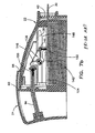
- the trigger is pivotally coupled at the top of the housing and is configured to be activated by the user rotating the trigger relative to the housing, such as with the thumb of the user's hand.
- An example of a dispenser according to this second arrangement is shown in, for example, Fig. 18 .
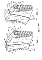
- FIG. 1 illustrates a "home" position
- Fig. 2 illustrates a "dispensed” position for dispenser 20.
- Dispenser 20 includes front grip section 26 and rear grip section 28, which, when pivoted together as shown in Fig. 2 and explained in detail below, causes an article 30 to be pushed at least partially out of exit 32.
- article 30 is a test strip, e.g., an Accu-Chek® brand glucose test strip that is commercially available from the assignee of the present invention.
- main housing 22 carries a stack 34 of test strips 30 to be successively dispensed from dispenser 20, as explained below.
- Housing 22 includes a window 36 ( Figs. 1 and 2 ) for viewing the quantity of articles 30 remaining in stack 34.
- Window 36 may be formed of any number of clear materials, e.g., clear polypropylene.
- housing 22 and trigger 24 are formed of polypropylene and polystyrene, respectively, but it should be readily appreciated that many other plastics, composites or other materials may be used.
- Grip section 26 includes protruding ribs 38 that are preferably formed of a thermoplastic elastomer such as Santoprene®, available from Advanced Elastomer Systems, Akron, OH.
- Exit 32 includes flaps 40 that define a lip seal 42. Flaps 40 are also made from Santoprene® and are integrally formed with ribs 38 as illustrated in Fig. 3 .
- trigger 24 and housing 22 are pivotably connected at bottom portions 44 and 46, respectively, which results in housing 22 nesting within trigger 24 mainly at the top of dispenser 20.
- the bottom portions of the trigger and housing do not significantly nest together, which allows cassette 84 ( Fig. 4 ) to be secured to the bottom of housing 22 without interference from trigger 24 when the two are pivoted together during dispensing.
- housing 22 includes cylindrical posts 48 extending laterally therefrom that are rotatably received in corresponding cylindrical openings 50 in trigger 24.
- the inside surface of trigger 24 is formed with slots 52 that lead to openings 50, which aids assembly of dispenser 20 by allowing posts 48 to slide through slots 52. While the illustrated embodiment includes posts 48 formed on housing 22 and openings 50 on trigger 24, the situation could be reversed. Further, other means for making the pivotal connection between housing 22 and trigger 24, e.g., a hinge, could be substituted for the posts and openings.
- Trigger 24 has a profile that substantially matches that of housing 22 but is slightly larger, such that the inner surface of trigger 24 defines a receptacle for housing 22.
- trigger 24 defines an arcuate inner wall 54 that has an arcuate profile similar to that of outer wall 56 defined by housing 22.
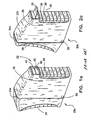
- trigger 24a partially nests within a receptacle defined by main housing 22a as the two parts are pivoted together, and a test strip 30 is expelled partially from container 20a.
- main housing 22a As shown in Figs. 1a and 2a , trigger 24a partially nests within a receptacle defined by main housing 22a as the two parts are pivoted together, and a test strip 30 is expelled partially from container 20a.
- Other variations of the housing would be recognized by one of ordinary skill in the art.
- one advantage of this pivoting housing is that the actuable parts of the housing that cause a strip to be dispensed can be made as large as the dispenser itself.
- dispensing a strip with dispenser 20 or 20a requires only an overall squeeze of the hand, and which does not require individual movement of the fingers. As noted above, this is especially advantageous to diabetics who have lost finger sensation and dexterity and thus have trouble manipulating the small dials, caps and sliders present in other prior art dispensers.
- a torsion spring 62 has upstanding legs 64 and 66 which push against the interior of trigger 24 and housing 22, respectively, biasing the dispenser in the home position shown in Fig. 1 .
- Spring 62 is held in place by means of channels 68 formed by spring retaining plates 70 and 72 formed in trigger 24 and which channels 68 captively hold legs 64.
- spring retaining plates 70 and 72 formed in trigger 24 and which channels 68 captively hold legs 64.
- trigger 24 includes a flange 58 that mates with an upstanding ridge 60.
- the inventive housing also includes a locking mechanism or "passive lock" that provides sufficient force to prevent the user from accidentally dispensing an article but not too much force to prevent intended dispensing. That is, the passive lock requires initially overcoming a greater force than that provided by spring 62.
- trigger 24 defines a home cavity or recess 72 that receives an ear or protrusion 74 formed on back plate 76 ( Fig. 4 ) when the dispenser is in the home position.
- an inclined recess 80 is provided to guide the protrusion 74 past wall 78 and into the recess 72 during initial assembly.
- a cassette 84 that carries stack 34 of test strips 30 is disposed within housing 22.
- the cassette is preferably made from a three-phase polymer that has moisture-absorbing properties, such as Active-Pak®, available from Capital Specialty Plastics, Auburn, AL, 2AP®, available from Südchemie Performance Packaging Europe, Choisy le Roi, France, and Flotech® "S", available from Grace
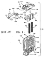
- cassette 84 The major components of cassette 84 include back plate 76, which is illustrated in Fig. 4 , and hollow body 86, top cap 88, pressure pad 90, pressure pad springs 92 and flexible arm member 94, which are illustrated in Fig. 6 .
- Pressure pad 90 carries the stack of test strips 34 and is movable vertically with respect to hollow body 86. Specifically, pressure pad 90 includes protrusions 96 that are slidingly received in guide slots 98. Two additional protrusions (not shown) extend from the back of pressure pad 90 and are slidingly received into guide slots 100 shown in Fig. 6 . The protrusions and guide slots maintain the pressure pad aligned as it advances upward as test strips are dispensed.
- Cassette 84 preferably holds a range from five to one-hundred fifty of the test strips 34. In the illustrated embodiment, cassette 84 holds fifty test strips.
- body 86 includes cylindrical spring retention posts 102 on which are received springs 92.
- Springs 92 extend into cylinders 106 formed in pressure pad 90, and their spring force biases the pressure pad upward as strips are dispensed.
- Top cap 88 is attached to hollow body 86 by means of anchor stanchions 112 that fit into slots 114.
- An opening 89 ( Fig. 4 ) is formed between top cap 88 and hollow body 86 to allow a strip to exit the cassette.
- the top cap is formed from polypropylene, although many other materials would be suitable.
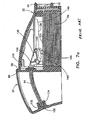
- Spring fingers 116 provide pressure to seat the cassette subassembly in housing 22 as can be seen with reference to Fig. 7a .
- a toe clip 118 extending from the bottom of body 86 guides the cassette in place during assembly and fits under front rail 120 ( Fig. 3 ) to hold the front of the cassette body 86 in the housing 22.
- Retention boss 122 retains the lower back half of the cassette subassembly in the housing 22.
- ribs 82 temporarily hold cassette 84 in place within housing 22.
- Back plate 76 is then welded to the main housing 22 and holds the cassette body 86 within housing 22, which means main housing 22 is essentially sealed from the ambient. The seal is only broken when aperture 124 in back plate 76 is unsealed while a test strip is being dispensed through lip seal 42.
- flexible arm member 94 includes a sealing member 126 that engages a sealing surface 128 when dispenser 20 is in the home position.
- Sealing member 126 has an "umbrella” type geometry that circumscribes the flexible arm member and that flexes to conform to the conical recess shape of sealing member 128, thereby forming a tight seal. Sealing member 126 is preferably formed from Santoprene®. When the trigger 24 is squeezed, arm member 94 is actuated and the seal is temporarily broken until dispenser 20 returns to the home position.
- sealing member 126 is attached to sealing surface 128, such that it stays in place when dispenser 20 is in the home and the dispensed positions.
- the sealing member 126 is configured such that flexible arm member 94 passes through the sealing member 126 when the trigger 24 is squeezed. Sealing member 126 circumscribes the flexible arm member 94 but allows arm member 94 to slide through sealing member 126.
- flexible arm member 94 is connected on one end to trigger housing 24 by means of clip fingers 130 that wrap around retention member 132. Ears 134 press against angled sides 135 of trigger housing 24 and prevent clips 130 from disengaging during operation of the dispenser.
- the flexible arm member terminates in a pusher head 136 that is positioned above the test strips and is slidably disposed in groove 138. More particularly, pusher head 136 includes cams 140 and posts 142 extending into grooves 138. The cams, posts and grooves comprise part of a guiding mechanism that moves the pusher head up and down as it reciprocates, as described in more detail below.
- the pusher head also includes resilient fingers or engagement members 144 that frictionally engage the top surface of the top test strip and slide it out of the dispenser, as discussed in more detail below.
- Pusher head 136 is preferably integrally formed with the remainder of flexible arm member 94 and is hingedly connected thereto by a "working hinge" 146.
- the working hinge provides stronger resistance than a normal "living hinge” but will still flex, allowing the pusher head to pivot or rotate down onto and up and away from the test strips.
- the flexible arm member 94 is formed from polypropylene, but one of ordinary skill in the art could substitute many other flexible materials.
- the inventive dispenser When not in use, the inventive dispenser is positioned in the "home" position depicted in Figs. 1a and 7a .
- the user begins to squeeze trigger 24 and housing 22 together, he or she must first overcome the "passive lock” described above. Thereafter, trigger 24 and housing 22 can be squeezed together against the force of spring 62, thereby defining a dispense stroke.
- flexible arm member 94 is coupled to trigger 24, the pivoting movement of the dispenser parts actuates the arm member and causes it to slide through aperture 124. The seal made by umbrella seal 126 is thus broken.
- arm member 94 has a profile that substantially matches that of aperture 124 such that arm member 94 engages the periphery of aperture 124 as it passes through it.
- a quasi-seal between arm member 94 and aperture 124 thus remains as arm member 94 slides through aperture 124.
- seal 126 moves away from aperture 124 when the dispenser is activated, because there is a close fit between arm member 94 and aperture 124, the seal there between is not significantly compromised.
- this initial movement of the arm member causes pusher head 136 to pivot about cams 140 from a disengaged station spaced away from the stack of strips to an engaged station in which fingers 144 frictionally engage the top test strip.
- cams 140 define a pivot axis and the sliding movement in the direction of arrow 150 of arm member 94 as shown in Fig. 7b is translated through working hinge 146 and produces a moment about cams 140.
- This causes pusher head 136 to pivot down as shown by arrow 152.
- the pusher head slides to the right as shown and the top strip displaces flaps 40 of lip seal 42 as it exits the dispenser.
- Test strips 30 can be arranged in cassette 84 such that a dosing end or a meter insertion end of the test strip 30 exits first as the pusher head slides to the right.
- groove 138 defines an inclined portion 148 at an end thereof.
- posts 142 are engaged by inclined portion 148, such that pusher head 136 pivots upward and away from the top test strip of the stack, as shown in Fig. 7c .
- This upward pivoting occurs despite there being a moment about cams 140 through the end of the dispense stroke.
- the top strip can be easily pulled from dispenser 20 against only a slight frictional force produced by lip seal 42.
- the flexible arm member flexes into a substantially straight configuration at the end of the dispense stroke as shown in Fig. 7c .
- the bending or straightening of arm member 94 is due to the fact that the end of arm member 94 that is coupled to trigger 24 moves upward relative to housing 22 as the housing and trigger are squeezed together.
- cams 140 As the user loosens his or her grip and allows spring 62 to return trigger 24 and housing 22 to the home position, an opposite moment is created about cams 140 as shown in Fig. 7d .
- the sliding movement in the direction of arrow 156 of arm member 94 as shown in Fig. 7d is translated through working hinge 146 and produces a moment about cams 140 which maintains the pusher head 136 in the disengaged position.
- the pusher head will not engage this top strip on the return stroke. That is, the top strip will not retract on the return stroke simply because the user fails to pull it from the dispenser before releasing the trigger and housing.
- lip seal 42 has automatically returned to its sealed or closed position on its own volition, thereby making it unnecessary for the user to remember to close the dispenser.
- the dispenser 20 can be integrated with a test meter that reads the test strips.
- the meter can also receive data from the test strip 30 and/or dispenser 20 and interpret the data.
- Dispenser 20 can be configured with a radio frequency identification (RFID) tag that stores information about the strips such as lot number, expiration date, type of test strip, among other information.
- RFID radio frequency identification
- the meter can be configured with an RFID reader which sends a signal to the RFID tag when the dispenser is brought within close proximity of the meter. The meter can thus receive the data that is stored on the RFID tag.
- the RFID reader and the RFID tag are referred to generally herein as an RFID system.
- the RFID reader includes a transceiver and an antenna that emits electromagnetic radio signals to activate the RFID tag, which includes its own transceiver and antenna. Interrogation signals from the reader activate the tag, causing the tag to send a return signal including the information encoded on the tag.
- the RFID system can operate via a technique known as continuous wave backscatter.
- the reader transmits a continuous-wave interrogation signal to the tag, and the tag modulates the continuous wave interrogation signal to produce a backscatter response signal that is transmitted back to the reader.
- This backscatter response signal includes the information encoded on the tag, such as the lot number, expiration date, calibration data or other information concerning the test strips.
- a variety of suitable RFID tag systems are commercially available. Presently, there are three main categories of commercially available RFID systems. There are systems that employ beam-powered passive tags, battery-powered semi-passive tags, and active tags.
- a beam-powered RFID tag is often referred to as a passive device, in that it derives the energy needed for its operation from the radio frequency energy beamed at it (from the reader). Such a passive tag rectifies the field and changes the reflective characteristics of the tag itself, creating a change in reflectivity (RF crosssection) that is then seen at the reader.
- a battery-powered semi-passive RFID tag operates in a similar fashion, modulating its RF cross-section in order to change its reflectivity that is seen at the interrogator to develop a communication link.
- the semi-passive RFID tag has a battery to provide the tag's operational power.
- both the tag and reader have transceivers to communicate and are each powered by their own batteries.
- housing 22 includes a lip seal cover 190 for covering the exit 32.
- Lip seal cover 190 has an inner surface 192 that defines a receptacle that receives protruding lip 194 of exit 32 by a friction fit engagement.
- the lip seal cover 190 is hingedly connected to housing 22.
- other means for making the connection between lip seal cover 190 and exit 32 e.g., a snap-on connection, could be substituted for the hinge connection.
- the lip seal cover 190 is pivoted away from the exit 32 by the user applying a finger or thumb to tab 196, which exposes the flaps 40 of lip seal 42, as shown in Fig. 9a .
- lip seal cover 190 When the dispenser is not in use, the lip seal cover 190 is positioned over the exit 32 to cover the flaps 40 of lip seal 42 as shown in Fig. 9b .
- Lip seal cover 190 may be formed of any number of materials such as plastics, composites, metals and the like.
- lip seal cover 190 acts as a dust cover for exit 32 and protects exit 32 from contact damage by items such as keys, coins, cosmetic containers, and the like when the dispenser is carried in a pocket or container having such items.
- housing 22 includes a platform 230 inserted between flaps 40 of lip seal 42 and integrally attached to the housing 22.
- the platform 230 is sized to fit within the lip seal 42 as shown in Fig. 10a .
- the platform 230 inserted between the flaps 40 acts as a plug and forms an airtight seal with the flaps 40.
- the test strip 30 displaces or biases the top flap outwardly as it exits the dispenser. Thereafter, top flap 40 will remain in an outward position, but remains nonetheless biased against platform 230.
- the platform 230 provides a surface that the test strip 30 can ride on or slide over as the test strip 30 passes through the lip seal 42. It should be appreciated that the dispenser could be configured to dispense test strips between the bottom flap and the platform or the top flap and the platform. Platform 230 may be formed of any number of materials such as plastics, composites, metals or other materials.
- housing 22 includes an exit 330 that can be reconfigured to form an airtight seal.
- seal 346 in a single step, e.g., by injection molding. It is further desirable to form ribs 38 ( Fig. 2 ) integrally with seal 346.
- ribs 38 Fig. 2
- One of the drawbacks of injection molding is that discontinuities such as lip seal 42 require a part in the mold that separates flaps 342 and 344 that are to be formed with the mold. If the seal 346 is to be integrally formed, it will thus include a small gap such as gap 348 illustrated in Fig. 11a between the two flaps.
- seal 346 depicted in Fig. 11a is unsuitable because it is not air-tight. Recognizing that a gap will be present in the originally molded part, the seal 346 shown in Fig. 11a is designed so that it can be "inverted” or “reconfigured” after initially being molded to form an airtight seal in which the two flaps not only contact one another, but are biased together.
- bottom flap 344 is angled to the left or inwardly of the dispenser and includes a nub 350 that points to the left or inside of the dispenser.
- Flap 342 is preferably angled opposite to flap 344 and also includes a nub 352 that points outwardly or to the right as shown in Fig. 11a .
- the flexible seal 346 can be reconfigured by inverting the position of the flaps such that flap 342 and flap 344 are biased against each other to form an airtight seal as shown in Fig. 11b .
- a force can be applied to the top flap 342 to push the top flap 342 to the left and over the bottom flap 344 and/or a force can be applied to the bottom flap 344 to push the bottom flap 344 to the right and under the top flap 342.
- the airtight seal shown in Fig. 11b can be formed by ejecting the first test strip from dispenser 20, during which the test strip will push flap 344 to the right, past flap 342. When the test strip is fully removed from the dispenser, the configuration shown in Fig. 11b will be achieved.
- seal 346 can be formed from Santoprene® or another elastic material that allows top flap 342 and bottom flap 344 to flex or bend. Additionally, the flexible seal 346 can be covered with a cap (see Fig. 9a ).
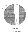
- housing 22 includes an exit 430 that can be reconfigured to form an airtight seal.
- exit 430 as molded includes top flap 442 and bottom flap 444 that form a flexible seal 446.
- the bottom flap 444 is positioned initially to the left of top flap 442.
- top flap 442 and bottom flap 444 are substantially in the same position as when the flexible seal 446 was formed or molded.
- the flexible seal 446 can be reconfigured by inverting the positions of the flaps such that flap 442 and flap 444 are biased against each other. For example, a force can be applied to the bottom flap 444 shown in Fig. 12a to push or pull it to the right and under the top flap 442.
- top flap 442 is displaced to the left of bottom flap 444. Further, the top flap 442 and the bottom flap 444 are biased together as shown by the arrows in Fig. 12b .
- the test strip displaces or biases apart the bottom flap 444 from the top flap 442 as it passes between the flaps to exit the dispenser.
- Top flap 442 and bottom flap 444 can be formed from Santoprene® or another elastic material that allows top flap 442 and bottom flap 444 to flex or bend.
- top flap 442 and/or bottom flap 444 can be integrally formed with ribs 38 (see Figs. 1 and 2 ). Additionally, the flexible seal 446 can be covered with a cap (see Fig. 9a ).
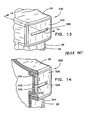
- housing 22 includes a cap 530 for covering exit 532.
- Cap 530 has an outer periphery that substantially matches that of exit 532 but is slightly smaller, such that cap 530 fits snugly within the periphery defined by exit 532.
- Cap 530 includes an opening 536 from which test strips 30 are dispensed.
- Cap 530 may be formed of any number of materials such as plastics, composites, metals or other materials.
- Cap 530 like lip seal cover 190, also acts as a dust cover for exit 532 and protects exit 532 from contact damage by foreign objects.
- Exit 532 includes flaps 540 that form a flexible seal 542 as shown in Fig. 14 .
- biasing members 534 are wedged between the housing 22 and the flaps 540 to reconfigure the flexible seal 542 as shown in Fig. 14 such that the biasing members 534 bias the flaps 540 together to form an airtight seal. That is, as cap 530 is installed into dispenser 20, wedge-shaped biasing members 534 are inserted between the housing 22 and seal 542 such that biasing members 534 squeeze the flaps 540 together.
- biasing members 534 are integrally formed with cap 530. When dispensing a test strip, the test strip displaces or biases apart the flaps 540 as it passes between the flaps 540 to exit the dispenser through opening 536.
- Flaps 540 can be formed of Santoprene® or another elastic material that allows the flaps 540 to flex or bend. Also, it should be appreciated that the embodiment shown in Figs. 9a-9b can also be configured to include biasing members that squeeze the flaps together.
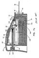
- housing 22 includes an exit 630 that can be reconfigured to form a substantially or completely airtight "duckbill" seal.
- Exit 630 is shaped as a duckbill with walls 640 that form an elongated channel 644, as illustrated in Fig. 15a .
- the walls 640 point to the left in Fig. 15a .
- walls 640 are substantially in the same position as when the flexible seal 642 was formed or molded.
- the seal 642 is preferably integrally formed by injection molding, the walls 640 define a gap 646 therebetween when the part leaves the mold from which it is made.
- the gap 646 can be eliminated by inverting or turning the duckbill seal 642 inside out, as can be appreciated by comparing Figs. 15a and 15b .
- the curved or profiled outer sides 648 of walls 640 shown in Fig. 15a become the inner walls of the seal shown in Fig. 15b , in which the walls 640 are biased together and form an air-tight seal, as indicated by the arrows in Fig. 15b .
- the profiled shape of walls 640 shown in Fig. 15a enhances the bias between walls 640 when the seal 642 is turned inside out to form the structure shown in Fig. 15b .
- Walls 640 can be formed from Santoprene® or another elastic material that allows the walls 640 to flex or bend. Further, walls 640 can be integrally formed with ribs 38 (see Figs. 1 and 2 ). In addition, the flexible seal 642 can be covered with a cap (see Fig. 9a ).
- the dispenser can be configured to facilitate inserting a strip into a meter without the need for the user to have to touch a strip.
- the stack of test strips is loaded into the dispenser such that the "meter insertion end" of the test strips exits the dispenser first upon dispensing. (This is opposite to that shown in Fig. 2 .)
- the dispenser is configured with an additional "detent" position between the home and dispense positions described above, which is used to hold the test strip in place after the end of it has extended from the dispenser.
- groove 138 defines a notch or detent 147 such that posts 142 engage the detent 147 as the pusher head 136 slides to the right as the user squeezes the trigger and housing together.
- the detent 147 is positioned such that the posts 142 are guided into it as the dispenser is actuated. This happens after test strip 30 has passed partially through lip seal 42 and has a portion thereof extending from the dispenser as shown. The user experiences a tactile sensation when the forward movement of pusher head 136 stops as the posts 142 engage the detent 147. In this detent position, the fingers 144 remain frictionally engaged with the top test strip. The fingers 144 captively hold the test strip 30 such that the meter insertion end of the test strip 30 extends from the exit 32 of the dispenser.
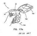
- test meter 700 has an opening 702 to receive the meter insertion end 33 of test strip 30.
- the user has squeezed trigger 24 and housing 22 together in the direction of arrows 704 to overcome the "passive lock” described above and has continued to squeeze trigger 24 and housing 22 together to the detent position.
- the detent position is signaled to the user through a tactile sensation produced by posts 142 engaging detent 147, at which point the forward movement of pusher head 136 stops.
- the meter insertion end 33 of the test strip 30 extends from exit 32 of dispenser 20 and fingers 144 remain frictionally engaged with the test strip.
- test meter 700 engages and captively holds the end of the test strip after it is inserted to the required depth.
- the meter and dispenser are in close proximity.
- the meter will download data from the RFID tag.
- data may include calibration data, expiration date and the like for the strips housed in dispenser 20.
- this information is included in a memory chip that is packaged with the vial. The memory chip must be inserted into the meter by the user before using the strips in a given vial.
- the RFID tag disclosed herein can avoid the need for these memory chips and the need for the user to have to insert them into the meter or otherwise code the meter for the test strips.
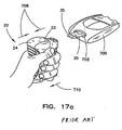
- the user then "releases” the test strip from the dispenser.
- this is done by fully squeezing the trigger 24 and the housing 22 together in the direction of arrows 708 to arrive at the "dispensed" position described above with respect to other embodiments. In the dispensed position, the fingers lift from the strip, thus releasing it.
- the dispenser can then be pulled away from the meter as shown by arrow 710 while leaving test strip 30 inserted in opening 702 of test meter 700, as shown in Fig. 17c . A dosing end 35 is thus protruding from the meter and is ready to receive a fluid sample.
- RFID reader power for proper operation of passive RFID systems is a function of distance, antenna sizes, frequency, and orientation. Most RFID systems are intended for near-field applications. Distances between readers and tags are normally on the order of millimeters.
- H IN / ( 2 ⁇ r ⁇ 1 + d 2 / r 2 1.5
- I current through reader antenna coil
- N number of turns on the reader antenna coil
- r radius of the reader antenna coil
- d distance between the center of the reader antenna coil & the center of the tag antenna coil.
- RFID systems used in the present invention can be configured to operate in a relatively short transmission range (on the order of inches), thus reducing transmission power requirements.
- the power of the interrogation signal is less than about 1 watt and in other embodiments is less than about 50 milliwatts.
- the overall power consumed by the reader to interrogate and read the RFID tag in one embodiment is less than about 325 milliwatts, and in other embodiments is less than about 30 milliwatts.
- an RFID communication protocol may be employed that limits communications attempts from the reader (i.e. the sending of interrogations signals) to situations where a tag is present to be read.
- One such protocol places the reader in sleep mode until a test strip is inserted into the meter. Insertion of the test strip activates the reader to send out its interrogation signal and to look for the response from the RFID tag. The response comes in a matter of milliseconds, and once the information from the RFID tag has been received at the meter, the reader goes back into battery conservation/sleep mode. Triggering the RFID tag interrogation signal based on the docking of a test strip into a meter serves to assure that communication is only attempted when the meter and the dispenser are in sufficiently close proximity.
- FIG. 18 illustrates a dispenser 900 according to an embodiment of the present invention.
- dispenser 900 is constructed to sequentially dispense test strips 30 out of an opening 932, and as illustrated has strip 33 extending from opening 932 so as to be ready to dock with meter 700.
- Dispenser 900 includes an RFID tag 999 snap fit into a receiving pocket 998 near opening 932 such that, when docked with meter 700 in the manner shown in Fig. 17a , the absolute distance between tag 999 and the reader in meter 700 is minimized.
- similar proximity can be achieved by locating tag 999 above or to the side of opening 932.
- tag 999 can be located anywhere in dispenser 900.
- dispenser 900 Aside from the inclusion of receiving pocket 998 for tag 999, the primary difference between dispensers 20 and 900 relates to the manner of activation by the user. More specifically, while each are constructed for one handed operation, dispenser 900 employs a trigger 924 rotatable about the housing 922 for activation whereas dispenser 20 utilizes squeeze action. As described more fully below with respect to Figs. 19-23 , the trigger 924 can be operated with the user's thumb while holding the dispenser 900. Such a construction provides a compact and user friendly device that, like the dispenser 20, is particularly suitable for operation by patients with limited dexterity in the hands.
- Dispenser 800 includes two main components: a main outer housing 822 and an inner cassette 884 that holds a stack 834 of test strips.
- a trigger 824 is pivotally mounted to the housing 822 and is coupled to a flexible arm 894.
- the housing 822 receives the cassette 884, as indicated by the downward arrows showing assembly direction in FIG. 22 , and a rigid portion 895 of flexible arm 894 couples via a yoke type coupling to pusher head 936.
- Pusher head 936 is slideably contained in cassette 884 above the test strip stack 834, and head 936 includes a friction pad with flexible fingers 936 for frictionally engaging the uppermost test strip in the stack 834.
- a pair of guide slots 938, 939 in cassette 884 receive corresponding guide followers 940, 891 on pusher head 936 and the rigid portion 895 of flexible arm 894, respectively.
- a user grips the dispenser and depresses the outer surface of trigger 824, for example at a frictional element such as ridge 823, with his thumb to pivot the trigger 824 about the axis defined by pin 801. This moves trigger 824 from the home/closed position ( Fig. 19 ) to the dispensed/open position ( Fig. 20 ) and causes arm 894 to cause pusher head 936 to slide from left to right in Figs. 19 and 20 .
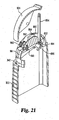
- Trigger 824 has a profile that substantially matches that of housing 822 but is slightly larger, such that the inner surface of trigger 824 defines a receptacle for housing 822. As shown more clearly in Fig. 21 , trigger 824 defines an arcuate inner wall 854 that has an arcuate profile similar to that of outer wall 856 defined by housing 822. Thus, when trigger 824 is rotated from a home position to a dispense position, housing 822 is substantially continually nested within trigger 824 while an article 33 is expelled partially from dispenser 800. Thus, trigger 824 is rotatable about the housing 822.
- a pusher pad pressure control follower 950 of pusher head 936 is received in detent 945 of a pressure control cam rail 946 of housing 822.
- cam rail 946 applies downward pressure, pressing the fingers 937 of head 936 against the top strip of stack 834 to achieve a secure frictional coupling.
- This frictional coupling forces the top strip out lip seal 842 as head 936 completes its operative stroke.
- follower 950 of head 936 reaches detent 947 (the dispensed position of Fig. 20 )
- the downward pressure is released, reducing the frictional engagement and allowing easy withdrawal of the strip from the dispenser 800.
- the cam rail 946 provides a biasing surface that follower 950 slides along to apply downward pressure on the pusher head 936 during its dispense stroke, and recesses 945, 947 in the biasing surface serve to reduce this downward pressure when the pusher head 936 is in its home and dispensed positions.
- flexible arm 894 follows a C-shaped or arcurate path and is at least partially guided therein by guide rail 893 (see Fig. 21 ).
- this arcuate path of arm 894 with be of relatively small size, for example portions having a radius of curvature less than 3, 2 or 1 inch.
- a substantial portion of the arcuate path, including, therefore, a substantial portion of the arm 864, is maintained above the stack 834 (per the views of Figs. 19 and 20 ) during the operative stroke.
- the trigger 824 is biased to be in the home, or closed position of Fig. 19 by a pair of elastic bands 960.
- Bands 960 are secured at one end (to housing 822) and have their open ends looped around one or more catches 963 formed on the inside of trigger 824.
- bands 960 are formed as a part of elastic member 961 which is a unitary elastomeric piece (e.g. Santoprene ®) that defines the lip seal 842 at one end and the bands 960 at another.
- bands and lip seal are separate pieces.
- fingers 937 there are four fingers 937 on the pusher head 936, each angled in the direction of dispensing.
- These fingers 937 are formed of a resilient material, such as rubber or polypropylene, and are rigid enough to remain angled in the direction of dispensing during the dispensing stroke, but are flexible enough to "give" during the return stoke.
- the bias of the bands 960 is sufficient to overcome the drag force of the fingers 937 against the top strip in the stack and to return the pusher head 936 to the home position ( Fig. 19 ).
- catches 963 also comprise a series of ratchet members 864 that interact with first and second pawls 962, 864 (also shown in perspective in Figs. 21 and 25 ) to indicate when the trigger 824 is in the home position or dispense position, respectively.
- first and second pawls 962, 864 also shown in perspective in Figs. 21 and 25
- the ratchet members 864 of catches 963 engage first pawls 962 to yieldingly retain the trigger 824 in the home position in order to reduce the chances that trigger 824 will be accidentally opened.
- the ratchet members 864 of catches 963 engage second pawls 864 to yieldingly retain the trigger 824 in the dispense position against the restoring force of bands 960.
- portion 825 of trigger 824 is covering and protecting the exit defined by lip seal 842.
- first pawls 962 are helping to protect and maintain the integrity of the seal 842.
- pawls 962 and/or bands 960 bias portion 825 of trigger 824 to contact and/or exert pressure on seal 842 to further help preserve its integrity.
- trigger 824 covers but does not directly contact seal 842.
- At least the upper portion of the inner cassette 884 is constructed in two pieces that are snapped and/or sealed together around the pusher head 936.
- Figs. 24 shows a perspective view of the pusher head 936 received in one half of the upper part of cassette 884
- Fig. 25 shows the Fig. 24 arrangement with the outer housing 882 attached over the cassette.
- the flexible arm 894 is not shown in Figs. 24 and 25 , but it is to be understood that, as depicted in Figs. 21 and 22 , the rigid portion 895 may be attached to the flexible arm 894 before being coupled to the pusher head 936.
- the cassette 884 and upper housing 822 cooperate to form a substantially airtight and/or moisture proof enclosure around the test strip stack 834, which serves to increase the shelf life of the test strips.
- the primary means for moisture in the air to access stack is via the path traveled by the flexible arm 894.
- an umbrella seal 892 is provided along arm 894 near the rigid portion 895 to form a seal along this path when the pusher head 936 is in its home position ( Fig. 19 ). It is to be understood that umbrella seal 892 mates with a corresponding recess in housing 822 in the same manner that umbrella sealing member 126 engages sealing surface 128 in device 20 above (see Figs. 5a and 5b ). Because the devices (20, 800) are in their home positions a majority of the time, this sealing from the external environment can substantially increase the shelf life of the test strips.
- a dessicant material is optionally provided at the bottom of the stack between cassette springs 892 for similar purposes.
Abstract
Description
- The present invention relates generally to dispensers and more particularly to dispensers for flattened articles such as test strips.
- Test strips or biosensors for measuring the presence or concentrations of selected analytes in test samples are well known. Typically, several of the test strips are packaged and stored in a disposable vial having a lid that snaps off or unscrews to open. Desiccant material is normally packaged within the vial to maintain the test strips dry. To conduct a test, the user must open the vial and remove a test strip. The strip is then typically inserted into a meter and a fluid sample (normally whole blood) is deposited onto it. The meter then measures the concentration of analyte using photometric or electrochemical methods. When the test is finished, the strip is removed from the meter and discarded. Also, before beginning use of a new vial of test strips, a user is typically given the opportunity to code the meter for the particular test strips, in other words input identifying information about the test strips (such as a calibration date, lot number, expiration date, etc.) into the meter. This coding is sometimes accomplished via a memory chip provided with the test strips that the user then manually inserts into the meter.
- Test strips are commonly used by diabetics to measure the level of glucose in their blood, which for most diabetics needs to be done three to four times per day, sometimes more frequently. Unfortunately, many diabetics develop complications from having the disease, such as impaired vision, loss of hand-eye coordination, and loss of sensitivity and dexterity of the fingers and toes. These complications of the disease can make opening a test strip vial, extracting a single test strip, manipulating the test strip and/or coding the meter quite difficult.
- Equally undesirably, opening a conventional vial of test strips exposes the strips to moisture in the atmosphere and causes the reagents contained in them to degrade much more quickly than if the vial remained sealed. This exposure significantly reduces shelf life.
- Accordingly, there are needs for advances in this area of technology. More specifically, but not exclusively, there are needs for dispensers that ease handling of the test strips and/or that provide for automatic coding of the meter.
- Dispensers providing solutions that ease handling of test strips including dispensers in accordance with the preamble of claim 1 are known from
US 2002/104849 A1 ,WO 2006/009534 A1 andUS 2005/281706 A1 . - The present invention provides substantially moisture-proof, airtight dispensers for both storing and dispensing several diagnostic test strips being inter alia suitable for further means for automatically, coding a meter with test strip information. The invention is discussed more fully below.
- The above-mentioned and other advantages of the present invention, and the manner of obtaining them, will become more apparent and the invention itself will be better understood by reference to the following description taken in conjunction with the accompanying drawings, wherein:
-
Figs. 1 and 2 are perspective views of an article dispenser in accordance with the prior art, illustrating the home and dispensed positions of the dispenser; -
Figs. 1a and 2a are perspective views of an alternate example of an article dispenser in accordance with the prior art, illustrating the home and dispensed positions of the dispenser; -
Fig. 3 is a perspective view in partial cross section of the dispenser shown inFigs. 1 and 2 , illustrating the interior components of the dispenser; -
Fig. 4 is an exploded perspective view of the dispenser shown inFigs. 1 and 2 ; -
Figs. 5a and5b are an enlarged fragmentary perspective view and a sectional view, respectively, of a seal in accordance with the prior art; -
Fig. 6 is an exploded perspective view of a dispenser body or cassette in accordance with the prior art; -
Figs. 7a-7d are side sectional views that illustrate the movement of a prior art dispenser from the home position to the dispense position and then back; -
Fig. 8a is an exploded perspective view with portions broken away of the dispenser ofFigs. 1 and 2 ; -
Fig. 8b is an enlarged fragmentary view of a locking mechanism in accordance with the prior art; -
Fig. 8c is an enlarged fragmentary perspective view illustrating the connection of a flexible arm member to a trigger; -
Figs. 9a and 9b are enlarged fragmentary perspective views illustrating a lip seal cover ; -
Figs. 10a and 10b are enlarged fragmentary perspective views in partial cross section illustrating a platform and a lip seal in accordance with the prior art; -
Fig. 11a and 11b are enlarged fragmentary perspective views in partial cross section illustrating a lip seal and a reconfigured lip seal, respectively, in accordance with the prior art; -
Figs. 12a and 12b are enlarged fragmentary perspective views in partial cross section illustrating another prior art lip seal and a reconfigured lip seal, respectively; -
Fig. 13 is an enlarged fragmentary perspective view illustrating a cap in accordance with the prior art; -
Fig. 14 is an enlarged fragmentary perspective view in partial cross section illustrating a cap and an exit in accordance with the prior art; -
Figs. 15a-15c are enlarged fragmentary perspective views in partial cross section illustrating a flexible seal, a reconfigured flexible seal, and a reconfigured flexible seal with an article exiting the seal, respectively, in accordance with the prior art; -
Fig. 16 is a side sectional view illustrating the movement of the prior art dispenser from the home position to an optional detent position; and -
Figs. 17a-17c are perspective views illustrating a method of using the article dispenser with a meter that reads the articles that are dispensed. -
Fig. 18 is a perspective view of an article dispenser with integrated RFID tag. -
Figs. 19 and20 are partial sectional views of an article dispenser of the flip top design in accordance with the present invention in the home and dispensed positions. -
Fig. 21 is a partial cutaway assembly view of the outer housing and trigger assembly of the dispenser ofFigs. 19 and20 . -
Fig. 22 is a sectional view of the housing and trigger assembly ofFig. 21 being inserted over the cassette to form the dispenser ofFigs. 19 and20 . -
Fig. 23 is a partial cutaway view of the trigger of the dispenser ofFigs. 19 and20 . -
Fig. 24 is an enlarged partial perspective view of the pusher head portion of the dispenser ofFigs. 19 and20 received in one half of the inner cassette. -
Fig. 25 is a view of the pusher head portion as shown inFig. 24 with the outer housing shown in cutaway. -
Fig. 26 is an enlarged view of the umbrella seal engaged with the outer housing to isolate the contents of the cassette from the external environment. - Corresponding reference characters indicate corresponding parts throughout the several views.
- For the purposes of prompting an understanding of the principles of the invention, reference will now be made to examples in accordance with the prior art and to specific embodiments illustrated herein and specific language will be used to describe the same. It will nevertheless be understood that no limitation of the scope of the invention is thereby intended, since the scope of the invention is defined by the claims. Any alterations and further modifications in the described processes or devices, and any further applications of the principles of the invention as described herein, are contemplated as would normally occur to one skilled in the art to which the invention relates.
- In one form, the present invention provides devices for storing and individually dispensing test strips. As described more fully below, these test strip dispensers include a housing that contains a stack of test strips and has an exit through which the strips are dispensed. A trigger is coupled to an actuator for individually advancing test strips from the stack through the exit. Various arrangements of the trigger and actuator are contemplated. In certain illustrated embodiments, the actuator includes a pusher head that is slidably disposed above the test strip stack and, upon activation, frictionally engages the top strip in the stack to advance that strip out of the exit.
- The trigger is adapted for ease of one-handed operation according to two basic arrangements. In the first arrangement in accordance with the prior art, the trigger is pivotally coupled to the housing and is activated by the user squeezing the trigger and housing together. In a preferred form of this arrangement, the trigger is located on one side of the dispenser with the test strips being ejected from the opposite side. An example of a dispenser according to this first arrangement is shown in, for example,
Figs. 1 and 2 . - In the second arrangement representing an embodiment of the claimed invention, the trigger is pivotally coupled at the top of the housing and is configured to be activated by the user rotating the trigger relative to the housing, such as with the thumb of the user's hand. An example of a dispenser according to this second arrangement is shown in, for example,
Fig. 18 . - Turning now to
Figs. 1 and 2 , a specific example of a dispenser according to the first arrangement is illustrated. However, it is be understood that, unless otherwise indicated, the principles of construction and operation of this first arrangement can be applied in the second arrangement as would occur to those of skill in the art.Article dispenser 20 for dispensing flattened articles such as biosensors or test strips is shown having amain housing 22 pivotably connected to a trigger orrear housing 24.Fig. 1 illustrates a "home" position whereasFig. 2 illustrates a "dispensed" position fordispenser 20.Dispenser 20 includesfront grip section 26 andrear grip section 28, which, when pivoted together as shown inFig. 2 and explained in detail below, causes anarticle 30 to be pushed at least partially out ofexit 32. In the illustrated embodiment,article 30 is a test strip, e.g., an Accu-Chek® brand glucose test strip that is commercially available from the assignee of the present invention. However, it should be understood that the teachings of the dispenser disclosed herein may be employed for dispensers of other flattened articles. As shown inFig. 3 ,main housing 22 carries astack 34 oftest strips 30 to be successively dispensed fromdispenser 20, as explained below.Housing 22 includes a window 36 (Figs. 1 and 2 ) for viewing the quantity ofarticles 30 remaining instack 34.Window 36 may be formed of any number of clear materials, e.g., clear polypropylene. - In the illustrated example,
housing 22 and trigger 24 are formed of polypropylene and polystyrene, respectively, but it should be readily appreciated that many other plastics, composites or other materials may be used.Grip section 26 includes protrudingribs 38 that are preferably formed of a thermoplastic elastomer such as Santoprene®, available from Advanced Elastomer Systems, Akron, OH.Exit 32 includesflaps 40 that define alip seal 42.Flaps 40 are also made from Santoprene® and are integrally formed withribs 38 as illustrated inFig. 3 . - With further reference to
Figs. 1 and 2 , trigger 24 andhousing 22 are pivotably connected atbottom portions housing 22 nesting withintrigger 24 mainly at the top ofdispenser 20. The bottom portions of the trigger and housing do not significantly nest together, which allows cassette 84 (Fig. 4 ) to be secured to the bottom ofhousing 22 without interference fromtrigger 24 when the two are pivoted together during dispensing. As shown inFig. 4 ,housing 22 includescylindrical posts 48 extending laterally therefrom that are rotatably received in correspondingcylindrical openings 50 intrigger 24. The inside surface oftrigger 24 is formed withslots 52 that lead toopenings 50, which aids assembly ofdispenser 20 by allowingposts 48 to slide throughslots 52. While the illustrated embodiment includesposts 48 formed onhousing 22 andopenings 50 ontrigger 24, the situation could be reversed. Further, other means for making the pivotal connection betweenhousing 22 andtrigger 24, e.g., a hinge, could be substituted for the posts and openings. - As shown in
Figs. 1 and 2 , since the pivotal connection is made atbottom portions trigger 24 andhousing 22 relative to one another occurs toward the top ofdispenser 20.Trigger 24 has a profile that substantially matches that ofhousing 22 but is slightly larger, such that the inner surface oftrigger 24 defines a receptacle forhousing 22. As shown more clearly inFig. 3 , trigger 24 defines an arcuateinner wall 54 that has an arcuate profile similar to that ofouter wall 56 defined byhousing 22. Thus, whentrigger 24 andhousing 22 are pivoted toward one another,housing 22 partially nests withintrigger 24 while anarticle 30 is expelled partially fromdispenser 20 as shown inFig. 2 . As shown inFig. 7c ,inner wall 54 andouter wall 56 approximate concentric segments whentrigger 24 andhousing 22 are pivoted together. - While in the preferred example the trigger forms the receptacle, the pivoting housing principle could be employed if the situation were reversed. As shown in
Figs. 1a and 2a , trigger 24a partially nests within a receptacle defined bymain housing 22a as the two parts are pivoted together, and atest strip 30 is expelled partially fromcontainer 20a. Other variations of the housing would be recognized by one of ordinary skill in the art. As noted above, one advantage of this pivoting housing is that the actuable parts of the housing that cause a strip to be dispensed can be made as large as the dispenser itself. Thus, dispensing a strip withdispenser - As shown in
Fig. 3 , atorsion spring 62 hasupstanding legs trigger 24 andhousing 22, respectively, biasing the dispenser in the home position shown inFig. 1 .Spring 62 is held in place by means ofchannels 68 formed byspring retaining plates trigger 24 and whichchannels 68 captively holdlegs 64. One of ordinary skill in the art would readily recognize many alternative spring mechanisms that could be configured and substituted for thetorsion spring 62 of the illustrated example. - To prevent
spring 62 from biasingtrigger 24 andhousing 22 beyond the home position and to prevent removal oftrigger 24 by a user,trigger 24 includes aflange 58 that mates with anupstanding ridge 60. The inventive housing also includes a locking mechanism or "passive lock" that provides sufficient force to prevent the user from accidentally dispensing an article but not too much force to prevent intended dispensing. That is, the passive lock requires initially overcoming a greater force than that provided byspring 62. With reference toFigs. 8a and8b , trigger 24 defines a home cavity orrecess 72 that receives an ear orprotrusion 74 formed on back plate 76 (Fig. 4 ) when the dispenser is in the home position. When the user squeezes the dispenser, sufficient force must be applied to unseat theprotrusion 74 from therecess 72. It has been found that a depth of about 0.5 mm forcavity 72 provides a passive lock that provides sufficient force to prevent accidental dispensing. As shown in the detail ofFig. 8b , aninclined recess 80 is provided to guide theprotrusion 74past wall 78 and into therecess 72 during initial assembly. - With reference to
Figs. 3 ,4 and6 , acassette 84 that carriesstack 34 oftest strips 30 is disposed withinhousing 22. The cassette is preferably made from a three-phase polymer that has moisture-absorbing properties, such as Active-Pak®, available from Capital Specialty Plastics, Auburn, AL, 2AP®, available from Südchemie Performance Packaging Europe, Choisy le Roi, France, and Flotech® "S", available from Grace - Davison, Worms, Germany. As noted above, the reagent materials contained in many test strips degrade when exposed to moisture, and housing them in a desiccant material such as
cassette 84 helps address this issue. - The major components of
cassette 84 include backplate 76, which is illustrated inFig. 4 , andhollow body 86,top cap 88,pressure pad 90, pressure pad springs 92 andflexible arm member 94, which are illustrated inFig. 6 .Pressure pad 90 carries the stack oftest strips 34 and is movable vertically with respect tohollow body 86. Specifically,pressure pad 90 includesprotrusions 96 that are slidingly received inguide slots 98. Two additional protrusions (not shown) extend from the back ofpressure pad 90 and are slidingly received intoguide slots 100 shown inFig. 6 . The protrusions and guide slots maintain the pressure pad aligned as it advances upward as test strips are dispensed. Once the protrusions reach the top end of the slots, further upward movement ofpressure pad 90 is prevented, which would occur when the dispenser is empty. When test strips 30 are present indispenser 20, upward movement ofpressure pad 90 is limited by the uppermost strip abutting againstshelves 104 formed intop cap 88. Similarly, the lowermost vertical position ofpressure pad 90 occurs when the protrusions reach the bottom of the slots, which occurs when the cassette is filled to capacity with test strips.Cassette 84 preferably holds a range from five to one-hundred fifty of the test strips 34. In the illustrated embodiment,cassette 84 holds fifty test strips. - With further reference to
Fig. 6 ,body 86 includes cylindrical spring retention posts 102 on which are receivedsprings 92.Springs 92 extend intocylinders 106 formed inpressure pad 90, and their spring force biases the pressure pad upward as strips are dispensed.Top cap 88 is attached to hollowbody 86 by means ofanchor stanchions 112 that fit intoslots 114. An opening 89 (Fig. 4 ) is formed betweentop cap 88 andhollow body 86 to allow a strip to exit the cassette. In the illustrated example, the top cap is formed from polypropylene, although many other materials would be suitable.Spring fingers 116 provide pressure to seat the cassette subassembly inhousing 22 as can be seen with reference toFig. 7a . Atoe clip 118 extending from the bottom ofbody 86 guides the cassette in place during assembly and fits under front rail 120 (Fig. 3 ) to hold the front of thecassette body 86 in thehousing 22. Retention boss 122 retains the lower back half of the cassette subassembly in thehousing 22. - With further reference to
Fig. 4 , during assembly ofdispenser 20,ribs 82 temporarily holdcassette 84 in place withinhousing 22. Backplate 76 is then welded to themain housing 22 and holds thecassette body 86 withinhousing 22, which meansmain housing 22 is essentially sealed from the ambient. The seal is only broken whenaperture 124 inback plate 76 is unsealed while a test strip is being dispensed throughlip seal 42. However, as shown inFigs. 5a and5b ,flexible arm member 94 includes a sealingmember 126 that engages a sealingsurface 128 whendispenser 20 is in the home position. Sealingmember 126 has an "umbrella" type geometry that circumscribes the flexible arm member and that flexes to conform to the conical recess shape of sealingmember 128, thereby forming a tight seal. Sealingmember 126 is preferably formed from Santoprene®. When thetrigger 24 is squeezed,arm member 94 is actuated and the seal is temporarily broken untildispenser 20 returns to the home position. - In an alternate example (not shown), sealing
member 126 is attached to sealingsurface 128, such that it stays in place whendispenser 20 is in the home and the dispensed positions. In this embodiment, the sealingmember 126 is configured such thatflexible arm member 94 passes through the sealingmember 126 when thetrigger 24 is squeezed. Sealingmember 126 circumscribes theflexible arm member 94 but allowsarm member 94 to slide through sealingmember 126. - As shown in
Figs. 6-8 ,flexible arm member 94 is connected on one end to triggerhousing 24 by means ofclip fingers 130 that wrap aroundretention member 132.Ears 134 press againstangled sides 135 oftrigger housing 24 and preventclips 130 from disengaging during operation of the dispenser. On its other end, the flexible arm member terminates in apusher head 136 that is positioned above the test strips and is slidably disposed ingroove 138. More particularly,pusher head 136 includescams 140 andposts 142 extending intogrooves 138. The cams, posts and grooves comprise part of a guiding mechanism that moves the pusher head up and down as it reciprocates, as described in more detail below. The pusher head also includes resilient fingers orengagement members 144 that frictionally engage the top surface of the top test strip and slide it out of the dispenser, as discussed in more detail below. -
Pusher head 136 is preferably integrally formed with the remainder offlexible arm member 94 and is hingedly connected thereto by a "working hinge" 146. The working hinge provides stronger resistance than a normal "living hinge" but will still flex, allowing the pusher head to pivot or rotate down onto and up and away from the test strips. In the illustrated embodiment, theflexible arm member 94 is formed from polypropylene, but one of ordinary skill in the art could substitute many other flexible materials. - When not in use, the inventive dispenser is positioned in the "home" position depicted in
Figs. 1a and7a . As the user begins to squeezetrigger 24 andhousing 22 together, he or she must first overcome the "passive lock" described above. Thereafter, trigger 24 andhousing 22 can be squeezed together against the force ofspring 62, thereby defining a dispense stroke. Sinceflexible arm member 94 is coupled to trigger 24, the pivoting movement of the dispenser parts actuates the arm member and causes it to slide throughaperture 124. The seal made byumbrella seal 126 is thus broken. Advantageously, however,arm member 94 has a profile that substantially matches that ofaperture 124 such thatarm member 94 engages the periphery ofaperture 124 as it passes through it. A quasi-seal betweenarm member 94 andaperture 124 thus remains asarm member 94 slides throughaperture 124. In other words, even thoughseal 126 moves away fromaperture 124 when the dispenser is activated, because there is a close fit betweenarm member 94 andaperture 124, the seal there between is not significantly compromised. - Turning now to
Figs. 7a and7b , this initial movement of the arm member causespusher head 136 to pivot aboutcams 140 from a disengaged station spaced away from the stack of strips to an engaged station in whichfingers 144 frictionally engage the top test strip. In other words,cams 140 define a pivot axis and the sliding movement in the direction ofarrow 150 ofarm member 94 as shown inFig. 7b is translated through workinghinge 146 and produces a moment aboutcams 140. This in turn causespusher head 136 to pivot down as shown byarrow 152. At the same time, the pusher head slides to the right as shown and the top strip displacesflaps 40 oflip seal 42 as it exits the dispenser.Lip seal 42 maintains a quasi-seal even asstrip 30 passes through it. Test strips 30 can be arranged incassette 84 such that a dosing end or a meter insertion end of thetest strip 30 exits first as the pusher head slides to the right. - As shown in
Fig. 7b ,groove 138 defines aninclined portion 148 at an end thereof. At the end of the dispense stroke,posts 142 are engaged byinclined portion 148, such thatpusher head 136 pivots upward and away from the top test strip of the stack, as shown inFig. 7c . This upward pivoting occurs despite there being a moment aboutcams 140 through the end of the dispense stroke. Advantageously, sincepusher head 136 is pivoted away from the top test strip, the top strip can be easily pulled fromdispenser 20 against only a slight frictional force produced bylip seal 42. The flexible arm member flexes into a substantially straight configuration at the end of the dispense stroke as shown inFig. 7c . The bending or straightening ofarm member 94 is due to the fact that the end ofarm member 94 that is coupled to trigger 24 moves upward relative tohousing 22 as the housing and trigger are squeezed together. - As the user loosens his or her grip and allows
spring 62 to returntrigger 24 andhousing 22 to the home position, an opposite moment is created aboutcams 140 as shown inFig. 7d . On the return stroke, the sliding movement in the direction ofarrow 156 ofarm member 94 as shown inFig. 7d is translated through workinghinge 146 and produces a moment aboutcams 140 which maintains thepusher head 136 in the disengaged position. Advantageously, even if the user loosens his or her grip before pulling the top strip completely from the dispenser, the pusher head will not engage this top strip on the return stroke. That is, the top strip will not retract on the return stroke simply because the user fails to pull it from the dispenser before releasing the trigger and housing. - It should be appreciated that after the strip is dispensed and the dispenser has returned to the home position,
lip seal 42 has automatically returned to its sealed or closed position on its own volition, thereby making it unnecessary for the user to remember to close the dispenser. - Optionally, the
dispenser 20 can be integrated with a test meter that reads the test strips. The meter can also receive data from thetest strip 30 and/ordispenser 20 and interpret the data.Dispenser 20 can be configured with a radio frequency identification (RFID) tag that stores information about the strips such as lot number, expiration date, type of test strip, among other information. The meter can be configured with an RFID reader which sends a signal to the RFID tag when the dispenser is brought within close proximity of the meter. The meter can thus receive the data that is stored on the RFID tag. The RFID reader and the RFID tag are referred to generally herein as an RFID system. - In one example of an RFID system suitable for use in embodiments of the present invention, the RFID reader includes a transceiver and an antenna that emits electromagnetic radio signals to activate the RFID tag, which includes its own transceiver and antenna. Interrogation signals from the reader activate the tag, causing the tag to send a return signal including the information encoded on the tag.
- The RFID system can operate via a technique known as continuous wave backscatter. In this technique, the reader transmits a continuous-wave interrogation signal to the tag, and the tag modulates the continuous wave interrogation signal to produce a backscatter response signal that is transmitted back to the reader. This backscatter response signal includes the information encoded on the tag, such as the lot number, expiration date, calibration data or other information concerning the test strips.
- A variety of suitable RFID tag systems are commercially available. Presently, there are three main categories of commercially available RFID systems. There are systems that employ beam-powered passive tags, battery-powered semi-passive tags, and active tags. A beam-powered RFID tag is often referred to as a passive device, in that it derives the energy needed for its operation from the radio frequency energy beamed at it (from the reader). Such a passive tag rectifies the field and changes the reflective characteristics of the tag itself, creating a change in reflectivity (RF crosssection) that is then seen at the reader. A battery-powered semi-passive RFID tag operates in a similar fashion, modulating its RF cross-section in order to change its reflectivity that is seen at the interrogator to develop a communication link. However, the semi-passive RFID tag has a battery to provide the tag's operational power. Finally, in the active RFID tag, both the tag and reader have transceivers to communicate and are each powered by their own batteries.
- In the illustrated example in
Figs. 9a-9b ,housing 22 includes alip seal cover 190 for covering theexit 32.Lip seal cover 190 has aninner surface 192 that defines a receptacle that receives protrudinglip 194 ofexit 32 by a friction fit engagement. As shown, thelip seal cover 190 is hingedly connected tohousing 22. However, other means for making the connection betweenlip seal cover 190 andexit 32, e.g., a snap-on connection, could be substituted for the hinge connection. When the dispenser is in use, thelip seal cover 190 is pivoted away from theexit 32 by the user applying a finger or thumb totab 196, which exposes theflaps 40 oflip seal 42, as shown inFig. 9a . When the dispenser is not in use, thelip seal cover 190 is positioned over theexit 32 to cover theflaps 40 oflip seal 42 as shown inFig. 9b .Lip seal cover 190 may be formed of any number of materials such as plastics, composites, metals and the like. Advantageously,lip seal cover 190 acts as a dust cover forexit 32 and protectsexit 32 from contact damage by items such as keys, coins, cosmetic containers, and the like when the dispenser is carried in a pocket or container having such items. - In the example illustrated in
Figs. 10a-10b ,housing 22 includes aplatform 230 inserted betweenflaps 40 oflip seal 42 and integrally attached to thehousing 22. Theplatform 230 is sized to fit within thelip seal 42 as shown inFig. 10a . When the dispenser is not in use, theplatform 230 inserted between theflaps 40 acts as a plug and forms an airtight seal with theflaps 40. As shown inFig. 10b , when dispensing thefirst test strip 30 from the dispenser, thetest strip 30 displaces or biases the top flap outwardly as it exits the dispenser. Thereafter,top flap 40 will remain in an outward position, but remains nonetheless biased againstplatform 230. Theplatform 230 provides a surface that thetest strip 30 can ride on or slide over as thetest strip 30 passes through thelip seal 42. It should be appreciated that the dispenser could be configured to dispense test strips between the bottom flap and the platform or the top flap and the platform.Platform 230 may be formed of any number of materials such as plastics, composites, metals or other materials. - As shown in
Figs. 11a-11b ,housing 22 includes anexit 330 that can be reconfigured to form an airtight seal. To achieve manufacturing efficiency, it is desirable to formseal 346 in a single step, e.g., by injection molding. It is further desirable to form ribs 38 (Fig. 2 ) integrally withseal 346. One of the drawbacks of injection molding is that discontinuities such aslip seal 42 require a part in the mold that separatesflaps seal 346 is to be integrally formed, it will thus include a small gap such asgap 348 illustrated inFig. 11a between the two flaps. - As formed,
seal 346 depicted inFig. 11a is unsuitable because it is not air-tight. Recognizing that a gap will be present in the originally molded part, theseal 346 shown inFig. 11a is designed so that it can be "inverted" or "reconfigured" after initially being molded to form an airtight seal in which the two flaps not only contact one another, but are biased together. Specifically,bottom flap 344 is angled to the left or inwardly of the dispenser and includes anub 350 that points to the left or inside of the dispenser.Flap 342 is preferably angled opposite toflap 344 and also includes anub 352 that points outwardly or to the right as shown inFig. 11a . However, after molding, theflexible seal 346 can be reconfigured by inverting the position of the flaps such thatflap 342 andflap 344 are biased against each other to form an airtight seal as shown inFig. 11b . For example, inFig. 11a , a force can be applied to thetop flap 342 to push thetop flap 342 to the left and over thebottom flap 344 and/or a force can be applied to thebottom flap 344 to push thebottom flap 344 to the right and under thetop flap 342. Alternatively, the airtight seal shown inFig. 11b can be formed by ejecting the first test strip fromdispenser 20, during which the test strip will pushflap 344 to the right,past flap 342. When the test strip is fully removed from the dispenser, the configuration shown inFig. 11b will be achieved. - Since
flap 342 as molded tends to point to the right andflap 344 as molded tends to point to the left, inverting the seal to the configuration shown inFig. 11b creates an advantageously airtight seal in which the flaps are pressed against one another. As shown reconfigured inFig. 11b , thetop flap 342 is displaced to the left ofbottom flap 344. Further, thetop flap 342 and thebottom flap 344 are biased together as shown by the arrows inFig. 11b . When dispensing a test strip, the test strip displaces or biases apart thebottom flap 344 from thetop flap 342 as it passes between the flaps and exits the dispenser. As described with reference to other embodiments, seal 346 can be formed from Santoprene® or another elastic material that allowstop flap 342 andbottom flap 344 to flex or bend. Additionally, theflexible seal 346 can be covered with a cap (seeFig. 9a ). - In the example illustrated in
Figs. 12a-12b ,housing 22 includes anexit 430 that can be reconfigured to form an airtight seal. As shown inFig. 12a ,exit 430 as molded includestop flap 442 andbottom flap 444 that form aflexible seal 446. Thebottom flap 444 is positioned initially to the left oftop flap 442. In this configuration,top flap 442 andbottom flap 444 are substantially in the same position as when theflexible seal 446 was formed or molded. Theflexible seal 446 can be reconfigured by inverting the positions of the flaps such thatflap 442 andflap 444 are biased against each other. For example, a force can be applied to thebottom flap 444 shown inFig. 12a to push or pull it to the right and under thetop flap 442. - As shown reconfigured in
Fig. 12b , thetop flap 442 is displaced to the left ofbottom flap 444. Further, thetop flap 442 and thebottom flap 444 are biased together as shown by the arrows inFig. 12b . When dispensing a test strip, the test strip displaces or biases apart thebottom flap 444 from thetop flap 442 as it passes between the flaps to exit the dispenser.Top flap 442 andbottom flap 444 can be formed from Santoprene® or another elastic material that allowstop flap 442 andbottom flap 444 to flex or bend. - Further,
top flap 442 and/orbottom flap 444 can be integrally formed with ribs 38 (seeFigs. 1 and 2 ). Additionally, theflexible seal 446 can be covered with a cap (seeFig. 9a ). - In the example illustrated in
Figs. 13-14 ,housing 22 includes acap 530 for coveringexit 532.Cap 530 has an outer periphery that substantially matches that ofexit 532 but is slightly smaller, such thatcap 530 fits snugly within the periphery defined byexit 532.Cap 530 includes anopening 536 from whichtest strips 30 are dispensed.Cap 530 may be formed of any number of materials such as plastics, composites, metals or other materials.Cap 530, likelip seal cover 190, also acts as a dust cover forexit 532 and protectsexit 532 from contact damage by foreign objects. -
Exit 532 includesflaps 540 that form aflexible seal 542 as shown inFig. 14 . Further, biasingmembers 534 are wedged between thehousing 22 and theflaps 540 to reconfigure theflexible seal 542 as shown inFig. 14 such that the biasingmembers 534 bias theflaps 540 together to form an airtight seal. That is, ascap 530 is installed intodispenser 20, wedge-shapedbiasing members 534 are inserted between thehousing 22 and seal 542 such that biasingmembers 534 squeeze theflaps 540 together. As shown, biasingmembers 534 are integrally formed withcap 530. When dispensing a test strip, the test strip displaces or biases apart theflaps 540 as it passes between theflaps 540 to exit the dispenser throughopening 536.Flaps 540 can be formed of Santoprene® or another elastic material that allows theflaps 540 to flex or bend. Also, it should be appreciated that the embodiment shown inFigs. 9a-9b can also be configured to include biasing members that squeeze the flaps together. - As shown in
Figs. 15a-15c ,housing 22 includes anexit 630 that can be reconfigured to form a substantially or completely airtight "duckbill" seal.Exit 630 is shaped as a duckbill withwalls 640 that form anelongated channel 644, as illustrated inFig. 15a . Thewalls 640 point to the left inFig. 15a . In this configuration,walls 640 are substantially in the same position as when theflexible seal 642 was formed or molded. As described elsewhere, since theseal 642 is preferably integrally formed by injection molding, thewalls 640 define agap 646 therebetween when the part leaves the mold from which it is made. However, thegap 646 can be eliminated by inverting or turning theduckbill seal 642 inside out, as can be appreciated by comparingFigs. 15a and 15b . The curved or profiledouter sides 648 ofwalls 640 shown inFig. 15a become the inner walls of the seal shown inFig. 15b , in which thewalls 640 are biased together and form an air-tight seal, as indicated by the arrows inFig. 15b . The profiled shape ofwalls 640 shown inFig. 15a enhances the bias betweenwalls 640 when theseal 642 is turned inside out to form the structure shown inFig. 15b . - When dispensing
test strip 30 as shown inFig. 15c , thetest strip 30 displaces or pushes apart the top wall from the bottom wall as it passes between thewalls 640 to exit the dispenser.Walls 640 can be formed from Santoprene® or another elastic material that allows thewalls 640 to flex or bend. Further,walls 640 can be integrally formed with ribs 38 (seeFigs. 1 and 2 ). In addition, theflexible seal 642 can be covered with a cap (seeFig. 9a ). - The dispenser can be configured to facilitate inserting a strip into a meter without the need for the user to have to touch a strip. For example, in
Fig. 16 , the stack of test strips is loaded into the dispenser such that the "meter insertion end" of the test strips exits the dispenser first upon dispensing. (This is opposite to that shown inFig. 2 .) Further, the dispenser is configured with an additional "detent" position between the home and dispense positions described above, which is used to hold the test strip in place after the end of it has extended from the dispenser. - With further reference to
Fig. 16 ,groove 138 defines a notch ordetent 147 such that posts 142 engage thedetent 147 as thepusher head 136 slides to the right as the user squeezes the trigger and housing together. Thedetent 147 is positioned such that theposts 142 are guided into it as the dispenser is actuated. This happens aftertest strip 30 has passed partially throughlip seal 42 and has a portion thereof extending from the dispenser as shown. The user experiences a tactile sensation when the forward movement ofpusher head 136 stops as theposts 142 engage thedetent 147. In this detent position, thefingers 144 remain frictionally engaged with the top test strip. Thefingers 144 captively hold thetest strip 30 such that the meter insertion end of thetest strip 30 extends from theexit 32 of the dispenser. - In this intermediate or detent position, the user can "dock"
dispenser 20 to a test meter to receive thetest strip 30. As shown inFigs. 17a-17c ,test meter 700 has anopening 702 to receive themeter insertion end 33 oftest strip 30. InFig. 17a , the user has squeezedtrigger 24 andhousing 22 together in the direction ofarrows 704 to overcome the "passive lock" described above and has continued to squeezetrigger 24 andhousing 22 together to the detent position. The detent position is signaled to the user through a tactile sensation produced byposts 142engaging detent 147, at which point the forward movement ofpusher head 136 stops. In this embodiment, themeter insertion end 33 of thetest strip 30 extends fromexit 32 ofdispenser 20 andfingers 144 remain frictionally engaged with the test strip. - The user then aligns the
end 33 of thetest strip 30 with theopening 702 and moves the dispenser in the direction ofarrow 706 inFig. 17b so that the meter insertion end of the test strip is inserted into opening 702 oftest meter 700. Preferably, thetest meter 700 engages and captively holds the end of the test strip after it is inserted to the required depth. - At this point, the meter and dispenser are in close proximity. If the dispenser is configured with the optional RFID tag noted above, and
meter 700 includes an RFID reader, the meter will download data from the RFID tag. Such data may include calibration data, expiration date and the like for the strips housed indispenser 20. In many traditional test strip vials, this information is included in a memory chip that is packaged with the vial. The memory chip must be inserted into the meter by the user before using the strips in a given vial. The RFID tag disclosed herein can avoid the need for these memory chips and the need for the user to have to insert them into the meter or otherwise code the meter for the test strips. - After the dispenser and meter are "docked" as shown in
Fig. 17b , the user then "releases" the test strip from the dispenser. With reference toFig. 17c , this is done by fully squeezing thetrigger 24 and thehousing 22 together in the direction ofarrows 708 to arrive at the "dispensed" position described above with respect to other embodiments. In the dispensed position, the fingers lift from the strip, thus releasing it. The dispenser can then be pulled away from the meter as shown byarrow 710 while leavingtest strip 30 inserted in opening 702 oftest meter 700, as shown inFig. 17c . Adosing end 35 is thus protruding from the meter and is ready to receive a fluid sample. - The range of communication for RFID tags in general depends upon the transmission power of the reader and of the tag, with a greater range requiring greater transmission power. RFID reader power for proper operation of passive RFID systems is a function of distance, antenna sizes, frequency, and orientation. Most RFID systems are intended for near-field applications. Distances between readers and tags are normally on the order of millimeters. An example of a simplified equation for inductive based passive devices that help illustrate the impact of distance changes is as follows:

where H = magnetic field intensity, I = current through reader antenna coil, N=number of turns on the reader antenna coil, r=radius of the reader antenna coil, d=distance between the center of the reader antenna coil & the center of the tag antenna coil. - However, these equations are typically useful only when the d is of the same order of magnitude as r (i.e., near-field).
- Because a passive tag derives its power from the interrogation signal of the reader, the transmission power is dependent on the transmission power of the reader. To reduce the power demands on the reader and prolong its battery life (and thereby the battery life of the reader), RFID systems used in the present invention can be configured to operate in a relatively short transmission range (on the order of inches), thus reducing transmission power requirements. For example, in one embodiment the power of the interrogation signal is less than about 1 watt and in other embodiments is less than about 50 milliwatts. In these or in other forms, the overall power consumed by the reader to interrogate and read the RFID tag in one embodiment is less than about 325 milliwatts, and in other embodiments is less than about 30 milliwatts.
- Limiting the RFID communications sessions to situations when the tag and reader are in close proximity further conserves battery life. For example, an RFID communication protocol may be employed that limits communications attempts from the reader (i.e. the sending of interrogations signals) to situations where a tag is present to be read. One such protocol places the reader in sleep mode until a test strip is inserted into the meter. Insertion of the test strip activates the reader to send out its interrogation signal and to look for the response from the RFID tag. The response comes in a matter of milliseconds, and once the information from the RFID tag has been received at the meter, the reader goes back into battery conservation/sleep mode. Triggering the RFID tag interrogation signal based on the docking of a test strip into a meter serves to assure that communication is only attempted when the meter and the dispenser are in sufficiently close proximity.
-
FIG. 18 illustrates adispenser 900 according to an embodiment of the present invention. Likedispenser 20 described above,dispenser 900 is constructed to sequentially dispensetest strips 30 out of anopening 932, and as illustrated hasstrip 33 extending from opening 932 so as to be ready to dock withmeter 700.Dispenser 900 includes anRFID tag 999 snap fit into a receivingpocket 998 near opening 932 such that, when docked withmeter 700 in the manner shown inFig. 17a , the absolute distance betweentag 999 and the reader inmeter 700 is minimized. Depending on the precise location of the RFID reader inmeter 700, similar proximity can be achieved by locatingtag 999 above or to the side ofopening 932. In still other variations, and particularly where close proximity is not needed, tag 999 can be located anywhere indispenser 900. - Aside from the inclusion of receiving
pocket 998 fortag 999, the primary difference betweendispensers dispenser 900 employs atrigger 924 rotatable about thehousing 922 for activation whereasdispenser 20 utilizes squeeze action. As described more fully below with respect toFigs. 19-23 , thetrigger 924 can be operated with the user's thumb while holding thedispenser 900. Such a construction provides a compact and user friendly device that, like thedispenser 20, is particularly suitable for operation by patients with limited dexterity in the hands. - Referring now to
Figs. 19-26 , the activation of the trigger will be described in connection withdispenser 800, which is a variation ofdispenser 900 without theRFID tag 999 or the receivingpocket 998.Dispenser 800 includes two main components: a mainouter housing 822 and aninner cassette 884 that holds astack 834 of test strips. Atrigger 824 is pivotally mounted to thehousing 822 and is coupled to aflexible arm 894. Thehousing 822 receives thecassette 884, as indicated by the downward arrows showing assembly direction inFIG. 22 , and arigid portion 895 offlexible arm 894 couples via a yoke type coupling topusher head 936.Pusher head 936 is slideably contained incassette 884 above thetest strip stack 834, andhead 936 includes a friction pad withflexible fingers 936 for frictionally engaging the uppermost test strip in thestack 834. A pair ofguide slots cassette 884 receive corresponding guidefollowers pusher head 936 and therigid portion 895 offlexible arm 894, respectively. In use, a user grips the dispenser and depresses the outer surface oftrigger 824, for example at a frictional element such asridge 823, with his thumb to pivot thetrigger 824 about the axis defined bypin 801. This movestrigger 824 from the home/closed position (Fig. 19 ) to the dispensed/open position (Fig. 20 ) and causesarm 894 to causepusher head 936 to slide from left to right inFigs. 19 and20 . - As shown in
Figs. 19 and20 , because the pivotal connection is made between a central lower portion of thetrigger 824 and a central upper portion of thehousing 822, the movement oftrigger 824 andhousing 822 relative to one another maintains the nesting relationship between them from the home position to the dispense position and back again.Trigger 824 has a profile that substantially matches that ofhousing 822 but is slightly larger, such that the inner surface oftrigger 824 defines a receptacle forhousing 822. As shown more clearly inFig. 21 ,trigger 824 defines an arcuate inner wall 854 that has an arcuate profile similar to that of outer wall 856 defined byhousing 822. Thus, whentrigger 824 is rotated from a home position to a dispense position,housing 822 is substantially continually nested withintrigger 824 while anarticle 33 is expelled partially fromdispenser 800. Thus, trigger 824 is rotatable about thehousing 822. - In the home position of
Fig. 19 , a pusher padpressure control follower 950 ofpusher head 936 is received indetent 945 of a pressurecontrol cam rail 946 ofhousing 822. Ashead 936 slides to the right,cam rail 946 applies downward pressure, pressing thefingers 937 ofhead 936 against the top strip ofstack 834 to achieve a secure frictional coupling. This frictional coupling forces the top strip outlip seal 842 ashead 936 completes its operative stroke. Whenfollower 950 ofhead 936 reaches detent 947 (the dispensed position ofFig. 20 ), the downward pressure is released, reducing the frictional engagement and allowing easy withdrawal of the strip from thedispenser 800. Ashead 936 returns to the home position, the next strip instack 834 is biased upward bycassette springs 892 to be in position for the next dispensing. Accordingly, thecam rail 946 provides a biasing surface thatfollower 950 slides along to apply downward pressure on thepusher head 936 during its dispense stroke, and recesses 945, 947 in the biasing surface serve to reduce this downward pressure when thepusher head 936 is in its home and dispensed positions. - During operation, and as shown in
Figs. 19 and20 ,flexible arm 894 follows a C-shaped or arcurate path and is at least partially guided therein by guide rail 893 (seeFig. 21 ). When sized as a handheld device, this arcuate path ofarm 894 with be of relatively small size, for example portions having a radius of curvature less than 3, 2 or 1 inch. Likewise, to achieve a compact device, a substantial portion of the arcuate path, including, therefore, a substantial portion of thearm 864, is maintained above the stack 834 (per the views ofFigs. 19 and20 ) during the operative stroke. - As shown more particularly in
Fig. 21 , thetrigger 824 is biased to be in the home, or closed position ofFig. 19 by a pair ofelastic bands 960.Bands 960 are secured at one end (to housing 822) and have their open ends looped around one ormore catches 963 formed on the inside oftrigger 824. In one embodiment,bands 960 are formed as a part ofelastic member 961 which is a unitary elastomeric piece (e.g. Santoprene ®) that defines thelip seal 842 at one end and thebands 960 at another. In other embodiments, bands and lip seal are separate pieces. - As depicted, there are four
fingers 937 on thepusher head 936, each angled in the direction of dispensing. Thesefingers 937 are formed of a resilient material, such as rubber or polypropylene, and are rigid enough to remain angled in the direction of dispensing during the dispensing stroke, but are flexible enough to "give" during the return stoke. Thus, the bias of thebands 960 is sufficient to overcome the drag force of thefingers 937 against the top strip in the stack and to return thepusher head 936 to the home position (Fig. 19 ). - Referring now to
Fig. 23 , in one embodiment, catches 963 also comprise a series ofratchet members 864 that interact with first andsecond pawls 962, 864 (also shown in perspective inFigs. 21 and25 ) to indicate when thetrigger 824 is in the home position or dispense position, respectively. In operation, whentrigger 824 is in the home position, theratchet members 864 ofcatches 963 engagefirst pawls 962 to yieldingly retain thetrigger 824 in the home position in order to reduce the chances that trigger 824 will be accidentally opened. Whentrigger 824 is opened, theratchet members 864 ofcatches 963 engagesecond pawls 864 to yieldingly retain thetrigger 824 in the dispense position against the restoring force ofbands 960. - In the closed position,
portion 825 oftrigger 824 is covering and protecting the exit defined bylip seal 842. Thus, by helping to keeptrigger 824 closed,first pawls 962 are helping to protect and maintain the integrity of theseal 842. Optionally,pawls 962 and/orbands 960bias portion 825 oftrigger 824 to contact and/or exert pressure onseal 842 to further help preserve its integrity. In other embodiments, trigger 824 covers but does not directly contactseal 842. - In one mode of construction, at least the upper portion of the
inner cassette 884 is constructed in two pieces that are snapped and/or sealed together around thepusher head 936.Figs. 24 shows a perspective view of thepusher head 936 received in one half of the upper part ofcassette 884, andFig. 25 shows theFig. 24 arrangement with the outer housing 882 attached over the cassette. Theflexible arm 894 is not shown inFigs. 24 and25 , but it is to be understood that, as depicted inFigs. 21 and22 , therigid portion 895 may be attached to theflexible arm 894 before being coupled to thepusher head 936. - The
cassette 884 andupper housing 822 cooperate to form a substantially airtight and/or moisture proof enclosure around thetest strip stack 834, which serves to increase the shelf life of the test strips. The primary means for moisture in the air to access stack is via the path traveled by theflexible arm 894. As shown in the enlarged view ofFIG. 25 , anumbrella seal 892 is provided alongarm 894 near therigid portion 895 to form a seal along this path when thepusher head 936 is in its home position (Fig. 19 ). It is to be understood thatumbrella seal 892 mates with a corresponding recess inhousing 822 in the same manner thatumbrella sealing member 126 engages sealingsurface 128 indevice 20 above (seeFigs. 5a and5b ). Because the devices (20, 800) are in their home positions a majority of the time, this sealing from the external environment can substantially increase the shelf life of the test strips. A dessicant material is optionally provided at the bottom of the stack between cassette springs 892 for similar purposes. - While the operation of the second arrangement of a dispenser has been described with respect to the particular embodiment of the figures, it is to be appreciated that a number of variations could also be employed. For example, other mechanisms for translating the pivoting motion of the trigger to linear motion of a test strip that do not rely on a flexible arm can be employed as would occur to those of skill in the art. For example a slotted cam arrangement could be coupled to the trigger to linearly drive an ejector pad when the top is flipped. In another example, a set of gears could be used to translate the motion of the trigger into a linear driving force to eject a test strip.
- While preferred embodiments incorporating the principles of the present invention has been disclosed hereinabove with reference to
figures 18-26 , the present invention is not limited to the disclosed embodiments. The scope of the invention is defined by the claims.
Claims (15)
- A dispenser for test strips (800), comprising:a housing (822) containing a stack of the test strips (834) and defining an exit through which the test strips are dispensed;an actuator for moving a first test strip (33) in the stack at least partially through the exit when the actuator is moved from a home position to a dispensed position; anda trigger (824) for moving the actuator from the home to the dispensed position;wherein the trigger (824) has a first portion adapted to be manually activated by a user and characterised in that the trigger (824) has a second portion (825) that covers the exit when the actuator is in the home position.
- The dispenser of claim 1 wherein the exit (932) comprises a flexible seal (842).
- The dispenser of claim 2 wherein the trigger (824) is biased to contact and apply pressure to the flexible seal (842) when the actuator is in the home position.
- The dispenser of claim 1 wherein the actuator includes a pusher head (936) slidably disposed in the housing (822) and a flexible arm (894) coupled to the trigger (824) and the pusher head (936), the pusher head (936) having an engagement member for engaging a first test strip (33) in the stack to move the first test strip at least partially through the exit.
- The dispenser of claim 1 further comprising a guide assembly (893) that biases the actuator against the top test strip (33) of the stack when the actuator is between its home and dispensed positions.
- The dispenser of claim 5 wherein the actuator comprises a pusher head (936) having a plurality of fingers (937).
- The dispenser of any of the preceding claims, wherein the housing (822) receives an inner cassette (884) that holds a stack (834) of test strips.
- The dispenser of any of claims 4 to 7, wherein the trigger (824) is pivotally mounted to the housing (822) and is coupled to the flexible arm (894).
- The dispenser of any of claims 4 to 8, wherein the flexible arm (894) comprises a rigid portion (895).
- The dispenser of any of claims 7 to 9, comprising a pair of guide slots (938, 939) in the cassette (884) that receive corresponding guide followers (940, 891) on pusher head (936) and the rigid portion (895) of flexible arm (894), respectively.
- The dispenser of any of claims 4 to 10, wherein a pusher pad pressure control follower (950) of the pusher head (936) is received in a detent (945) of a pressure control cam rail (946) of the housing (822).
- The dispenser of claim 11, wherein the cam rail (946) provides a biasing surface that follower (950) slides along to apply downward pressure on the pusher head (936) during its dispense stroke.
- The dispenser of claim 12, further comprising recesses (945, 947) in the biasing surface that reduce the downward pressure when the pusher head (936) is in its home and dispensed positions.
- The dispenser of any of the preceding claims, wherein the trigger (824) is biased to be in the home or closed position by a pair of elastic bands (960).
- The dispenser of any of claims 7-14, wherein the cassette (884) and upper housing (822) cooperate to form a substantially airtight and/or moisture proof enclosure around the test strip stack (834).
Applications Claiming Priority (2)
| Application Number | Priority Date | Filing Date | Title |
|---|---|---|---|
| US11/394,776 US20060182656A1 (en) | 2004-06-18 | 2006-03-31 | Dispenser for flattened articles |
| PCT/EP2007/002852 WO2007112961A2 (en) | 2006-03-31 | 2007-03-30 | Dispenser for flattened articles |
Publications (3)
| Publication Number | Publication Date |
|---|---|
| EP2005158A2 EP2005158A2 (en) | 2008-12-24 |
| EP2005158B1 true EP2005158B1 (en) | 2010-12-15 |
| EP2005158B8 EP2005158B8 (en) | 2011-02-02 |
Family
ID=38197767
Family Applications (1)
| Application Number | Title | Priority Date | Filing Date |
|---|---|---|---|
| EP07723794A Not-in-force EP2005158B8 (en) | 2006-03-31 | 2007-03-30 | Dispenser for flattened articles |
Country Status (5)
| Country | Link |
|---|---|
| US (1) | US20060182656A1 (en) |
| EP (1) | EP2005158B8 (en) |
| AT (1) | ATE491944T1 (en) |
| DE (1) | DE602007011239D1 (en) |
| WO (1) | WO2007112961A2 (en) |
Families Citing this family (27)
| Publication number | Priority date | Publication date | Assignee | Title |
|---|---|---|---|---|
| US20060133956A1 (en) * | 2004-12-09 | 2006-06-22 | Kenichi Hamanaka | Test strip holder |
| US7887757B2 (en) * | 2006-05-09 | 2011-02-15 | Becton, Dickinson And Company | Method and apparatus for dispensing diagnostic test strips |
| DE102006045952A1 (en) * | 2006-09-28 | 2008-04-03 | Chia-Nan Wang | Bio sensor for parameter configuration, has radio frequency identification device system, micro processing unit, memory unit, indicator, power supply unit and control strip interface |
| US9052305B2 (en) | 2007-03-06 | 2015-06-09 | Lifescan, Inc. | Test strip dispenser |
| US20080217353A1 (en) * | 2007-03-06 | 2008-09-11 | Michael John Newman | Method of Dispensing A Test Strip |
| US20080230554A1 (en) * | 2007-03-23 | 2008-09-25 | Randolph Maryann | Chewing gum dispenser |
| US7935307B2 (en) * | 2007-05-31 | 2011-05-03 | EOS Health, DVC. | Disposable, refillable glucometer with cell phone interface for transmission of results |
| EP2052678A1 (en) * | 2007-10-24 | 2009-04-29 | F. Hoffmann-Roche AG | Medical system with monitoring of consumables |
| US8001825B2 (en) * | 2007-11-30 | 2011-08-23 | Lifescan, Inc. | Auto-calibrating metering system and method of use |
| US8454904B2 (en) * | 2008-07-29 | 2013-06-04 | Roche Diagnostics Operations, Inc. | Biosensor container |
| US8147755B2 (en) * | 2008-11-26 | 2012-04-03 | Roche Diagnostics Operations, Inc. | Drum type container for analytical elements |
| US8550295B2 (en) * | 2010-02-22 | 2013-10-08 | Roche Diagnostics Operations, Inc. | Container for dispensing a single test strip |
| US20110278321A1 (en) * | 2010-05-11 | 2011-11-17 | Roche Diagnostics Operations, Inc. | Hermetically sealed test strip container |
| US8702967B2 (en) | 2010-06-17 | 2014-04-22 | Bayer Healthcare Llc | Test strip with magneto-elastic-resonance sensor |
| EP2400411A1 (en) | 2010-06-24 | 2011-12-28 | Roche Diagnostics GmbH | Analysis system with expanded user information |
| US10352921B2 (en) * | 2011-05-31 | 2019-07-16 | Tara Chand Singhal | Integrated blood glucose measuring device with a test strip packaging system |
| US20120306628A1 (en) * | 2011-05-31 | 2012-12-06 | Tara Chand Singhal | Integrated blood glucose measurement device with a test strip count system |
| US9194837B2 (en) | 2011-08-24 | 2015-11-24 | Bayer Healthcare Llc | Analyte sensors and systems including retention tab and methods of manufacturing same |
| EP2793687B1 (en) | 2011-12-20 | 2017-05-10 | Ascensia Diabetes Care Holdings AG | Linear, cartridge-based glucose measurement system |
| US9383333B2 (en) * | 2012-05-31 | 2016-07-05 | Ascensia Diabetes Care Holdings Ag | Replaceable multistrip cartridge and biosensor meter |
| EP2856155B1 (en) | 2012-05-31 | 2017-05-24 | Ascensia Diabetes Care Holdings AG | Multistrip cartridge |
| WO2014118359A1 (en) * | 2013-02-04 | 2014-08-07 | Clariant Production (France) Sas | Dispensing device for holding and dispensing strip-like objects |
| US10533949B2 (en) | 2013-03-12 | 2020-01-14 | Ascensia Diabetes Care Holdings Ag | Test strip meter with a mechanism for pushing the test strip against an optical reader |
| CN110068674B (en) * | 2014-06-05 | 2020-09-08 | 豪夫迈·罗氏有限公司 | Exchangeable test element holder |
| EP3663759A1 (en) * | 2014-06-19 | 2020-06-10 | Ascensia Diabetes Care Holdings AG | Sensor clip assembly for stacked sensor dispensing system |
| CN104914239A (en) * | 2015-06-29 | 2015-09-16 | 上海交通大学 | Immunochromatographic test strip detection equipment |
| US11158150B2 (en) * | 2018-03-07 | 2021-10-26 | Stephen James Wilson | Battery storage and dispensing apparatus |
Family Cites Families (9)
| Publication number | Priority date | Publication date | Assignee | Title |
|---|---|---|---|---|
| US5244116A (en) * | 1992-04-06 | 1993-09-14 | Leo Daniel W | Cosmetic sample dispenser with replaceable magazines |
| DE19811622A1 (en) * | 1998-03-17 | 1999-09-23 | Lre Technology Partner Gmbh | Laboratory instrument incorporating split test card housing |
| PT1261860E (en) * | 2000-03-09 | 2007-03-30 | Clinical Analysis Corp | Medical diagnostic system |
| US7063234B2 (en) * | 2000-12-29 | 2006-06-20 | Csp Technologies, Inc. | Meter strip dispenser assembly |
| US6814844B2 (en) * | 2001-08-29 | 2004-11-09 | Roche Diagnostics Corporation | Biosensor with code pattern |
| CA2460904C (en) * | 2001-09-19 | 2011-03-22 | Advent Pharmaceuticals Pty Ltd | An inhaler for delivering metered doses of powdered medicament |
| DE10397016A5 (en) * | 2002-07-02 | 2015-05-28 | Panasonic Healthcare Holdings Co., Ltd. | Biosensor, biosensor chip and biosensor device |
| WO2006009534A1 (en) * | 2004-06-18 | 2006-01-26 | Roche Diagnostics Gmbh | Dispenser for flattened articles such as diagnostic test strips |
| US7582262B2 (en) * | 2004-06-18 | 2009-09-01 | Roche Diagnostics Operations, Inc. | Dispenser for flattened articles |
-
2006
- 2006-03-31 US US11/394,776 patent/US20060182656A1/en not_active Abandoned
-
2007
- 2007-03-30 AT AT07723794T patent/ATE491944T1/en not_active IP Right Cessation
- 2007-03-30 EP EP07723794A patent/EP2005158B8/en not_active Not-in-force
- 2007-03-30 DE DE602007011239T patent/DE602007011239D1/en active Active
- 2007-03-30 WO PCT/EP2007/002852 patent/WO2007112961A2/en active Application Filing
Also Published As
| Publication number | Publication date |
|---|---|
| EP2005158A2 (en) | 2008-12-24 |
| WO2007112961A3 (en) | 2008-01-10 |
| WO2007112961A2 (en) | 2007-10-11 |
| DE602007011239D1 (en) | 2011-01-27 |
| US20060182656A1 (en) | 2006-08-17 |
| EP2005158B8 (en) | 2011-02-02 |
| ATE491944T1 (en) | 2011-01-15 |
Similar Documents
| Publication | Publication Date | Title |
|---|---|---|
| EP2005158B1 (en) | Dispenser for flattened articles | |
| US7582262B2 (en) | Dispenser for flattened articles | |
| EP1761770B1 (en) | Dispenser for flattened articles such as diagnostic test strips | |
| US11391721B2 (en) | Test sensor cartridges and sensor-dispensing instruments | |
| EP1368262B1 (en) | Meter strip dispenser assembly | |
| US7638095B2 (en) | Personal portable blood glucose meter with replaceable cartridge of test strips | |
| EP1967852B1 (en) | Test Strip dispenser | |
| EP2856168B1 (en) | Replaceable multistrip cartridge and biosensor meter | |
| US20080032407A1 (en) | Sensor dispensing instrument having a pull/push activation mechanism | |
| EP2526029B1 (en) | Test strip container with strip retainer and methods of manufacturing and utilization thereof | |
| US8161617B2 (en) | Method of manufacturing a device for storing and dispensing liquid | |
| US4984288A (en) | Lead refill cartridge for mechanical pencil | |
| KR101787857B1 (en) | Dispensing device for holding and dispensing strip-like objects | |
| JP2022550689A (en) | Method and Portable Reader for Analyzing Biological Fluid Specimens | |
| CN102565412A (en) | Distributor for flat articles such as diagnosis test strips |
Legal Events
| Date | Code | Title | Description |
|---|---|---|---|
| PUAI | Public reference made under article 153(3) epc to a published international application that has entered the european phase |
Free format text: ORIGINAL CODE: 0009012 |
|
| 17P | Request for examination filed |
Effective date: 20081031 |
|
| AK | Designated contracting states |
Kind code of ref document: A2 Designated state(s): AT BE BG CH CY CZ DE DK EE ES FI FR GB GR HU IE IS IT LI LT LU LV MC MT NL PL PT RO SE SI SK TR |
|
| RIN1 | Information on inventor provided before grant (corrected) |
Inventor name: YODER, RANDY EDWARD Inventor name: STRANKO, SCOTT, K. Inventor name: ARNOLD, PETER, L. Inventor name: JOSEPH, ABNER, DAVID Inventor name: FUNKE, TOM |
|
| 17Q | First examination report despatched |
Effective date: 20090701 |
|
| GRAP | Despatch of communication of intention to grant a patent |
Free format text: ORIGINAL CODE: EPIDOSNIGR1 |
|
| GRAS | Grant fee paid |
Free format text: ORIGINAL CODE: EPIDOSNIGR3 |
|
| GRAA | (expected) grant |
Free format text: ORIGINAL CODE: 0009210 |
|
| AK | Designated contracting states |
Kind code of ref document: B1 Designated state(s): AT BE BG CH CY CZ DE DK EE ES FI FR GB GR HU IE IS IT LI LT LU LV MC MT NL PL PT RO SE SI SK TR |
|
| REG | Reference to a national code |
Ref country code: CH Ref legal event code: EP Ref country code: GB Ref legal event code: FG4D |
|
| RAP2 | Party data changed (patent owner data changed or rights of a patent transferred) |
Owner name: ROCHE DIAGNOSTICS GMBH Owner name: F.HOFFMANN-LA ROCHE AG |
|
| REG | Reference to a national code |
Ref country code: IE Ref legal event code: FG4D |
|
| REF | Corresponds to: |
Ref document number: 602007011239 Country of ref document: DE Date of ref document: 20110127 Kind code of ref document: P |
|
| REG | Reference to a national code |
Ref country code: NL Ref legal event code: VDEP Effective date: 20101215 |
|
| PG25 | Lapsed in a contracting state [announced via postgrant information from national office to epo] |
Ref country code: LT Free format text: LAPSE BECAUSE OF FAILURE TO SUBMIT A TRANSLATION OF THE DESCRIPTION OR TO PAY THE FEE WITHIN THE PRESCRIBED TIME-LIMIT Effective date: 20101215 |
|
| LTIE | Lt: invalidation of european patent or patent extension |
Effective date: 20101215 |
|
| PG25 | Lapsed in a contracting state [announced via postgrant information from national office to epo] |
Ref country code: CY Free format text: LAPSE BECAUSE OF FAILURE TO SUBMIT A TRANSLATION OF THE DESCRIPTION OR TO PAY THE FEE WITHIN THE PRESCRIBED TIME-LIMIT Effective date: 20101215 Ref country code: FI Free format text: LAPSE BECAUSE OF FAILURE TO SUBMIT A TRANSLATION OF THE DESCRIPTION OR TO PAY THE FEE WITHIN THE PRESCRIBED TIME-LIMIT Effective date: 20101215 Ref country code: AT Free format text: LAPSE BECAUSE OF FAILURE TO SUBMIT A TRANSLATION OF THE DESCRIPTION OR TO PAY THE FEE WITHIN THE PRESCRIBED TIME-LIMIT Effective date: 20101215 Ref country code: LV Free format text: LAPSE BECAUSE OF FAILURE TO SUBMIT A TRANSLATION OF THE DESCRIPTION OR TO PAY THE FEE WITHIN THE PRESCRIBED TIME-LIMIT Effective date: 20101215 Ref country code: NL Free format text: LAPSE BECAUSE OF FAILURE TO SUBMIT A TRANSLATION OF THE DESCRIPTION OR TO PAY THE FEE WITHIN THE PRESCRIBED TIME-LIMIT Effective date: 20101215 Ref country code: SI Free format text: LAPSE BECAUSE OF FAILURE TO SUBMIT A TRANSLATION OF THE DESCRIPTION OR TO PAY THE FEE WITHIN THE PRESCRIBED TIME-LIMIT Effective date: 20101215 Ref country code: BG Free format text: LAPSE BECAUSE OF FAILURE TO SUBMIT A TRANSLATION OF THE DESCRIPTION OR TO PAY THE FEE WITHIN THE PRESCRIBED TIME-LIMIT Effective date: 20110315 Ref country code: SE Free format text: LAPSE BECAUSE OF FAILURE TO SUBMIT A TRANSLATION OF THE DESCRIPTION OR TO PAY THE FEE WITHIN THE PRESCRIBED TIME-LIMIT Effective date: 20101215 |
|
| PG25 | Lapsed in a contracting state [announced via postgrant information from national office to epo] |
Ref country code: ES Free format text: LAPSE BECAUSE OF FAILURE TO SUBMIT A TRANSLATION OF THE DESCRIPTION OR TO PAY THE FEE WITHIN THE PRESCRIBED TIME-LIMIT Effective date: 20110326 Ref country code: PT Free format text: LAPSE BECAUSE OF FAILURE TO SUBMIT A TRANSLATION OF THE DESCRIPTION OR TO PAY THE FEE WITHIN THE PRESCRIBED TIME-LIMIT Effective date: 20110415 Ref country code: EE Free format text: LAPSE BECAUSE OF FAILURE TO SUBMIT A TRANSLATION OF THE DESCRIPTION OR TO PAY THE FEE WITHIN THE PRESCRIBED TIME-LIMIT Effective date: 20101215 Ref country code: BE Free format text: LAPSE BECAUSE OF FAILURE TO SUBMIT A TRANSLATION OF THE DESCRIPTION OR TO PAY THE FEE WITHIN THE PRESCRIBED TIME-LIMIT Effective date: 20101215 Ref country code: CZ Free format text: LAPSE BECAUSE OF FAILURE TO SUBMIT A TRANSLATION OF THE DESCRIPTION OR TO PAY THE FEE WITHIN THE PRESCRIBED TIME-LIMIT Effective date: 20101215 Ref country code: IS Free format text: LAPSE BECAUSE OF FAILURE TO SUBMIT A TRANSLATION OF THE DESCRIPTION OR TO PAY THE FEE WITHIN THE PRESCRIBED TIME-LIMIT Effective date: 20110415 Ref country code: GR Free format text: LAPSE BECAUSE OF FAILURE TO SUBMIT A TRANSLATION OF THE DESCRIPTION OR TO PAY THE FEE WITHIN THE PRESCRIBED TIME-LIMIT Effective date: 20110316 |
|
| PG25 | Lapsed in a contracting state [announced via postgrant information from national office to epo] |
Ref country code: RO Free format text: LAPSE BECAUSE OF FAILURE TO SUBMIT A TRANSLATION OF THE DESCRIPTION OR TO PAY THE FEE WITHIN THE PRESCRIBED TIME-LIMIT Effective date: 20101215 Ref country code: SK Free format text: LAPSE BECAUSE OF FAILURE TO SUBMIT A TRANSLATION OF THE DESCRIPTION OR TO PAY THE FEE WITHIN THE PRESCRIBED TIME-LIMIT Effective date: 20101215 Ref country code: PL Free format text: LAPSE BECAUSE OF FAILURE TO SUBMIT A TRANSLATION OF THE DESCRIPTION OR TO PAY THE FEE WITHIN THE PRESCRIBED TIME-LIMIT Effective date: 20101215 |
|
| PLBE | No opposition filed within time limit |
Free format text: ORIGINAL CODE: 0009261 |
|
| STAA | Information on the status of an ep patent application or granted ep patent |
Free format text: STATUS: NO OPPOSITION FILED WITHIN TIME LIMIT |
|
| PG25 | Lapsed in a contracting state [announced via postgrant information from national office to epo] |
Ref country code: DK Free format text: LAPSE BECAUSE OF FAILURE TO SUBMIT A TRANSLATION OF THE DESCRIPTION OR TO PAY THE FEE WITHIN THE PRESCRIBED TIME-LIMIT Effective date: 20101215 Ref country code: MC Free format text: LAPSE BECAUSE OF NON-PAYMENT OF DUE FEES Effective date: 20110331 |
|
| REG | Reference to a national code |
Ref country code: CH Ref legal event code: PL |
|
| 26N | No opposition filed |
Effective date: 20110916 |
|
| PG25 | Lapsed in a contracting state [announced via postgrant information from national office to epo] |
Ref country code: MT Free format text: LAPSE BECAUSE OF FAILURE TO SUBMIT A TRANSLATION OF THE DESCRIPTION OR TO PAY THE FEE WITHIN THE PRESCRIBED TIME-LIMIT Effective date: 20101215 |
|
| REG | Reference to a national code |
Ref country code: IE Ref legal event code: MM4A |
|
| REG | Reference to a national code |
Ref country code: DE Ref legal event code: R097 Ref document number: 602007011239 Country of ref document: DE Effective date: 20110916 |
|
| PG25 | Lapsed in a contracting state [announced via postgrant information from national office to epo] |
Ref country code: CH Free format text: LAPSE BECAUSE OF NON-PAYMENT OF DUE FEES Effective date: 20110331 Ref country code: LI Free format text: LAPSE BECAUSE OF NON-PAYMENT OF DUE FEES Effective date: 20110331 Ref country code: IE Free format text: LAPSE BECAUSE OF NON-PAYMENT OF DUE FEES Effective date: 20110330 |
|
| PG25 | Lapsed in a contracting state [announced via postgrant information from national office to epo] |
Ref country code: LU Free format text: LAPSE BECAUSE OF NON-PAYMENT OF DUE FEES Effective date: 20110330 |
|
| PG25 | Lapsed in a contracting state [announced via postgrant information from national office to epo] |
Ref country code: TR Free format text: LAPSE BECAUSE OF FAILURE TO SUBMIT A TRANSLATION OF THE DESCRIPTION OR TO PAY THE FEE WITHIN THE PRESCRIBED TIME-LIMIT Effective date: 20101215 |
|
| PG25 | Lapsed in a contracting state [announced via postgrant information from national office to epo] |
Ref country code: HU Free format text: LAPSE BECAUSE OF FAILURE TO SUBMIT A TRANSLATION OF THE DESCRIPTION OR TO PAY THE FEE WITHIN THE PRESCRIBED TIME-LIMIT Effective date: 20101215 |
|
| REG | Reference to a national code |
Ref country code: FR Ref legal event code: PLFP Year of fee payment: 10 |
|
| REG | Reference to a national code |
Ref country code: DE Ref legal event code: R081 Ref document number: 602007011239 Country of ref document: DE Owner name: ROCHE DIABETES CARE GMBH, DE Free format text: FORMER OWNER: ROCHE DIAGNOSTICS GMBH, 68305 MANNHEIM, DE |
|
| REG | Reference to a national code |
Ref country code: FR Ref legal event code: PLFP Year of fee payment: 11 |
|
| REG | Reference to a national code |
Ref country code: FR Ref legal event code: PLFP Year of fee payment: 12 |
|
| PGFP | Annual fee paid to national office [announced via postgrant information from national office to epo] |
Ref country code: IT Payment date: 20190319 Year of fee payment: 13 Ref country code: GB Payment date: 20190227 Year of fee payment: 13 Ref country code: DE Payment date: 20190215 Year of fee payment: 13 |
|
| PGFP | Annual fee paid to national office [announced via postgrant information from national office to epo] |
Ref country code: FR Payment date: 20190220 Year of fee payment: 13 |
|
| REG | Reference to a national code |
Ref country code: DE Ref legal event code: R119 Ref document number: 602007011239 Country of ref document: DE |
|
| PG25 | Lapsed in a contracting state [announced via postgrant information from national office to epo] |
Ref country code: DE Free format text: LAPSE BECAUSE OF NON-PAYMENT OF DUE FEES Effective date: 20201001 Ref country code: FR Free format text: LAPSE BECAUSE OF NON-PAYMENT OF DUE FEES Effective date: 20200331 |
|
| GBPC | Gb: european patent ceased through non-payment of renewal fee |
Effective date: 20200330 |
|
| PG25 | Lapsed in a contracting state [announced via postgrant information from national office to epo] |
Ref country code: GB Free format text: LAPSE BECAUSE OF NON-PAYMENT OF DUE FEES Effective date: 20200330 |
|
| PG25 | Lapsed in a contracting state [announced via postgrant information from national office to epo] |
Ref country code: IT Free format text: LAPSE BECAUSE OF NON-PAYMENT OF DUE FEES Effective date: 20200330 |