EP2004504B1 - Method and tradeable packet for holding a portable data storage medium - Google Patents
Method and tradeable packet for holding a portable data storage medium Download PDFInfo
- Publication number
- EP2004504B1 EP2004504B1 EP07723636A EP07723636A EP2004504B1 EP 2004504 B1 EP2004504 B1 EP 2004504B1 EP 07723636 A EP07723636 A EP 07723636A EP 07723636 A EP07723636 A EP 07723636A EP 2004504 B1 EP2004504 B1 EP 2004504B1
- Authority
- EP
- European Patent Office
- Prior art keywords
- data carrier
- identification information
- outer packaging
- information
- code
- Prior art date
- Legal status (The legal status is an assumption and is not a legal conclusion. Google has not performed a legal analysis and makes no representation as to the accuracy of the status listed.)
- Not-in-force
Links
- 238000000034 method Methods 0.000 title claims abstract description 30
- 238000013500 data storage Methods 0.000 title 1
- 238000004806 packaging method and process Methods 0.000 claims description 38
- 238000004519 manufacturing process Methods 0.000 claims description 9
- 238000010348 incorporation Methods 0.000 claims 1
- 239000012780 transparent material Substances 0.000 claims 1
- 239000000969 carrier Substances 0.000 description 7
- 238000012545 processing Methods 0.000 description 7
- 238000013461 design Methods 0.000 description 4
- 238000007639 printing Methods 0.000 description 3
- 239000000853 adhesive Substances 0.000 description 2
- 230000001070 adhesive effect Effects 0.000 description 2
- 238000005304 joining Methods 0.000 description 2
- 239000011159 matrix material Substances 0.000 description 2
- 238000000926 separation method Methods 0.000 description 2
- 101100079986 Caenorhabditis elegans nrfl-1 gene Proteins 0.000 description 1
- 238000004026 adhesive bonding Methods 0.000 description 1
- 238000004364 calculation method Methods 0.000 description 1
- 238000005516 engineering process Methods 0.000 description 1
- 238000003780 insertion Methods 0.000 description 1
- 230000037431 insertion Effects 0.000 description 1
- 238000002955 isolation Methods 0.000 description 1
- 238000002372 labelling Methods 0.000 description 1
- 239000000463 material Substances 0.000 description 1
- 238000012858 packaging process Methods 0.000 description 1
- 229920003023 plastic Polymers 0.000 description 1
- 238000002360 preparation method Methods 0.000 description 1
- 238000007789 sealing Methods 0.000 description 1
- 238000012800 visualization Methods 0.000 description 1
- 238000003466 welding Methods 0.000 description 1
Images


Classifications
-
- B—PERFORMING OPERATIONS; TRANSPORTING
- B65—CONVEYING; PACKING; STORING; HANDLING THIN OR FILAMENTARY MATERIAL
- B65B—MACHINES, APPARATUS OR DEVICES FOR, OR METHODS OF, PACKAGING ARTICLES OR MATERIALS; UNPACKING
- B65B9/00—Enclosing successive articles, or quantities of material, e.g. liquids or semiliquids, in flat, folded, or tubular webs of flexible sheet material; Subdividing filled flexible tubes to form packages
- B65B9/02—Enclosing successive articles, or quantities of material between opposed webs
- B65B9/04—Enclosing successive articles, or quantities of material between opposed webs one or both webs being formed with pockets for the reception of the articles, or of the quantities of material
-
- B—PERFORMING OPERATIONS; TRANSPORTING
- B65—CONVEYING; PACKING; STORING; HANDLING THIN OR FILAMENTARY MATERIAL
- B65B—MACHINES, APPARATUS OR DEVICES FOR, OR METHODS OF, PACKAGING ARTICLES OR MATERIALS; UNPACKING
- B65B25/00—Packaging other articles presenting special problems
- B65B25/14—Packaging paper or like sheets, envelopes, or newspapers, in flat, folded, or rolled form
-
- B—PERFORMING OPERATIONS; TRANSPORTING
- B65—CONVEYING; PACKING; STORING; HANDLING THIN OR FILAMENTARY MATERIAL
- B65B—MACHINES, APPARATUS OR DEVICES FOR, OR METHODS OF, PACKAGING ARTICLES OR MATERIALS; UNPACKING
- B65B61/00—Auxiliary devices, not otherwise provided for, for operating on sheets, blanks, webs, binding material, containers or packages
- B65B61/02—Auxiliary devices, not otherwise provided for, for operating on sheets, blanks, webs, binding material, containers or packages for perforating, scoring, slitting, or applying code or date marks on material prior to packaging
- B65B61/025—Auxiliary devices, not otherwise provided for, for operating on sheets, blanks, webs, binding material, containers or packages for perforating, scoring, slitting, or applying code or date marks on material prior to packaging for applying, e.g. printing, code or date marks on material prior to packaging
Definitions
- the invention relates to the packaging of mass-produced, suitable for the identification of a user portable data carriers in tradable individual packaging.
- the invention relates to the packaging of SIM ( Subscriber Identity Module ) modules in individual packaging.
- a method for packaging magnetic stripe cards in shipping bags is known.
- the magnetic stripe cards and the shipping bags are printed with matching information, such as the name of a future cardholder.
- the information is also coded in the magnetic stripe and printed again on the mailer in the form of a machine-readable barcode.
- the applied information Prior to assembling the magnetic stripe card and shipping pouch, the applied information is checked for compliance.
- the magnetic strip on the one hand and the machine-readable barcode on the other hand are read.
- the method allows a machine to perform the packaging process and ensures that personalized cards arrive only in their respective shipping bags.
- the method assumes that the shipping bags are completely personalized when they are brought together with the cards to be packaged. It is not suitable for applications in which the individualization of a package takes place only after assembly with a disk to be packaged.
- the outer packaging consists essentially of a molded transparent plastic material, which is held by a support frame, which consists for example of paper.
- an identity card which is provided on one side with a person identifying information such as in particular a photo and personal data and carries a two-dimensional barcode on the back.
- the two-dimensional barcode also contains in machine-readable form the data identifying the person.
- Two-dimensional barcodes contain information in coded form along a main direction and perpendicular to this main direction.
- Two-dimensional barcodes are known in various configurations, such as under the designation PDF 417 or as so-called matrix code, both of which are described in international standards.
- a method for producing a chip card shipping unit which consists of an envelope in which a cover letter and a shipping envelope with one or more smart cards are inserted.
- the shipping envelope consists of a series of contiguous individual pockets, which were cut off, for example, from a continuous shipping envelope. In each individual pocket a chip card is placed.
- Shipping envelope and cover letter are each provided with a matching identification code.
- Several shipping envelopes can carry the same identification code. By means of the identification code, shipping envelopes and cover letters are brought together.
- plain text data can also be applied to the envelope or its back. The application of plain text data is completely independent. The success of the process depends on the correct application of the identification codes to shipping envelopes and cover letters. If an error occurs here, this leads to an incorrect assignment of chip cards and cover letters.
- a mailing envelope for DVDs which includes a window through which a code attached to a DVD is readable.
- the code is read by machine and allows the assignment of the DVD to a receiver whose address is applied to the outside of the envelope.
- the solution is also designed exclusively for postal mail and does not provide any form of visualization of a different area of a DVD in addition to the machine code.
- the data carrier associated with ID information is no longer applied as before on the visible side of the disk but on the bottom and read from there through the Umverpakkung through the ID information to regain and be able to apply to the outer packaging.
- the application of the ID information to the underside of the data carrier has the advantage that as a rule the entire surface of the data carrier can be used and the ID information can be correspondingly formed over a large area or more extensively.
- the inventive method allows the fully automated packaging of very small-sized data carriers. These can be provided in an advantageous manner, in particular in a roll or in the form of strips, from which they are separated by machine for packaging.
- the inventive method is particularly advantageous for packaging SIM cards or chip cards of comparable or even smaller size, which are provided in a roll or in strips of a plurality of individual cards.
- the ID information is applied in the form of a two-dimensional barcode.
- the ID information is also invisible to the naked eye or at least difficult to recognize and readable only with a special reader.
- the packaging is preferably designed to be transparent at the placement location of the data carrier.
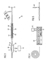
- a portable data carrier to be packaged is based on a known, standard SIM module, as shown in FIGS Fig. 1 and 2 is indicated.
- the basis of a SIM module as a design for a portable data carrier 10 takes place only as an example for the purpose of easier description. Nevertheless, the proposed method is also equally successful for other data carrier design forms which have a visible side which is considerably occupied by technical or informative elements and an underside which has no or little occupancy.
- the SIM module 10 referred to below simply as a module, has a flat, approximately rectangular shape with a visible side 12, on which a contact pad 14 is formed, and a planar underside 16.
- a module is located in the module 10, which is inaccessible from the outside 11, in which a secret software code is stored.
- the chip is connected to the contact pad 14.
- the contact field 14 typically covers more than half of the visible side 12.
- an information field 18 is formed in which information about the module are displayed.
- the information field 18 typically contains identification information for the unambiguous designation of the module 10 as well as information about the distributor of the module 10.
- the machine-readable code 20 is preferably a two-dimensional barcode, hereinafter this embodiment is used.
- the barcode 20 expediently covers all or most of the underside 16, so that the largest possible embodiment of the partial areas of the barcode 20 is achieved.
- the barcode 20 also contains the unique identification of the module 10 serving identification information.
- the two-dimensional barcode 20 may contain further information, such as information about the distributor of the module 10, the module manufacturer or features of the module 10.
- the two-dimensional barcode 20 a Contain control information by means of which in the chip 11 of the module 10 located secret software code is identifiable.
- the two-dimensional barcode 20 is preferably embodied in a form which is invisible to the naked eye or at least difficult to recognize. For example, it is such that it is visible only in ultraviolet light.
- the two-dimensional barcode 20 is a "matrix code" as defined in international standard ISO / IEC 16022. In this embodiment, it can be read omnidirectionally by means of CCD camera scanners, whereby a successful reading is also possible if up to 25% of the code could not be detected.
- other designs are possible, for example according to the type "PDF 417".
- the module 10 as in FIG Fig. 3 illustrated packaged in a tradable package 30.
- the tradable package 30 allows the shipment of the product contained, ie the module 10, and can be delivered without further action to an end user.
- the package 30 consists of an outer packaging, in which the module 10 and an accessory pack 50 are introduced and on the outside of a label 60 or a print is applied.
- the outer packaging is formed by joining together a lower mold 34 and an upper mold 40 and has cavities 42 and 44 which enclose the module 10 and the accessory pack 50.
- the cavities 42 and 44 are formed by conformal troughs 36, 38 and 46, 48, respectively, which are formed in the lower mold 34 and in the upper mold 40, respectively.
- the troughs 36, 38, 46, 48 each define a fixed placement within the outer packaging for the module 10 or the accessory pack 50 and secure them against slipping.
- the entire outer packaging, or at least parts of it are transparent.
- the upper mold 40 is transparent in such a way that through the upper mold 40th through the visible side 12 of the module 10 and the accessories 50 are visible.
- the lower mold 34 and upper mold 40 are suitably joined together along the edges by suitable methods such as welding, gluing or riveting.
- the accessory pack 50 contains information about the module 10. Typically, it contains instructions for use as well as a reproduction of the secret software code of the module 10.
- the secret code is reproduced on a sheet 52 which is inserted into the accessory pack 50 so that it is in an unopened form Accessory 50 can not be read from the outside.
- the identification information contained in the information field 18 is contained in the accessory pack 50, preferably on the sheet 52.
- the accessory pack 50 is a booklet or leaflet.
- the label 60 preferably also carries in plain text the identification information used for unambiguous identification of the module 10. It is applied after closing the outer package by joining the lower mold 34 and the upper mold 40 on the outside of the outer packaging, preferably on the outside of the upper mold 40. In conjunction with the identification information contained in the information field 18 on the module 10, the tag 60 allows checking whether the module 10, the accessory bag 50 and the label 60 belong to one another. In addition, information on handling the package 30 may be applied to the label 60, for example logistic information.
- the label 60 consists in a conventional manner of an adhesive carrier on which information is printed. In a variant, it is possible to dispense with the adhesive carrier and apply the information directly to the upper mold 40, for example by printing or by means of a laser.
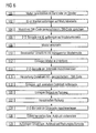
- the flow chart reproduced in the following is the preparation of the in Fig. 1 shown tradeable package 30 described.
- the production begins, step 100, with the provision of a module 10.
- the module 10 can, as in Fig. 4 illustrated, in particular in the form of a roll or in the form of strips of a plurality of modules 10 are provided.
- the individual modules 10 are still connected to each other via later to be removed webs 80. Depending on the separation technology used later, however, the webs 80 may also be omitted.
- the modules 10 have a longer and a shorter main axis, as is the case in particular for the underlying SIM modules, they are preferably as in FIG Fig. 4 indicated, connected along the longer major axis in the role or in the strip.
- the module 10 is first graphically individualized, step 102. On the visible side 12 of the modules provided for this purpose, a module 10 uniquely identifying identification information is applied to the information field 18.
- the module 10 is electrically personalized, step 104.
- a secret software code is generated and written into the chip 11 of the module 10.
- the secret software code typically comprises a PIN and a PUK for identifying a subscriber with respect to a mobile radio network.
- the secret software code written in the chip 11 is further stored outside the module 10 in a production database 82 along with the identification information applied in step 102.
- the two-dimensional barcode 20 is applied to the underside 16 of the module 10, which also contains the identification information and possibly further information.
- steps 102 to 106 can be carried out completely in the roll or in the strip.
- the modules 10 are separated in the following step 108.
- One possible form of isolation is in Fig. 5 illustrated. She can, as in Fig. 4 indicated, take place with the aid of a mechanical separating device 84, which separates the modules 10 directly in their final size from the strip or the role.
- any other known technique can be used for singling.
- the lower mold 34 is then provided, step 110.
- troughs 36 and 38 are formed for receiving the module 10 and the accessories 50.
- At least the trough 36 is designed to be transparent, so that the two-dimensional barcode 20 can subsequently be read out by means of a reading device 70 through the lower mold 34.
- the module 10, step 112 is inserted into the depression 36 which is mounted to receive the module 10.
- the two-dimensional barcode 20 is read out by means of a reading device 70 in a following step 114. From the read two-dimensional barcode 20, the identification information contained therein is determined. Under access to the production database 82, the secret software code stored in step 104 and belonging to the data carrier 10 is thus determined. This is transmitted, preferably in plain text, to a sheet 52, step 116, which is then inserted into the accessory pack 50 or optionally also glued, step 118.
- the accessory pack 50 is then also inserted into the recess 38 also provided in the lower mold 34, step 120.
- the accessory pack 50 is first inserted without the sheet 52 together with the module 10 in the prepared recess 38 and the sheet 52 then Inserted in the tray 38 placed in the trough 38.
- step 122 the lower mold 34 and the upper mold 40 are joined together and the package 30 is closed, step 122.
- the two-dimensional barcode 20 on the underside of the module 10 is read out through the lower mold 34 again by means of a reading device 70, which may be other than that used for the first reading in step 114, step 124.
- a reading device 70 which may be other than that used for the first reading in step 114, step 124.
- the identification information contained therein is determined and, preferably in plain text, applied to a label 60, step 126.
- the label is then, step 128, applied to the outside of the package 30.
- the identification information is applied directly to the outside of the pact 30, preferably as a print.
- preparing an imprint is carried out, which is then applied in step 128.
- printing techniques are considered, such as printing by means of an ink-jet printer or the blackening of the package outside by means of a laser beam.
- the label 60 or the imprint is placed on the outside of the upper mold 40 so that it can be read from the same side as the information field 18 on the module 10.
- the identification information can be applied to the label 60 more information, such as information on product labeling for the trade or information about the manufacturer of the module 10.
- the additional information can also be applied in machine-readable form, in particular as a common barcode or again as a two-dimensional barcode.
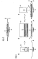
- FIG. 7 an implementation of the above-described method by means of successive processing stations 86, 88, 90 is illustrated.
- magazines 92, 94, 96 are arranged, from which in each case the modules 10, the Beipacke 50 and the labels 60 are supplied.
- a variant of a package 30 is made, in which, unlike the embodiment according to Fig. 3 , the two troughs 36, 38 are designed to receive module 10 and accessories 50 on top of each other in the form of a two-stage trough, the package 30 is in Fig. 7 shown in cross section.
- the information field 18 is covered in this arrangement by the accessory pack 50 and can be read only after opening the package 30.
- Fig. 8 shows the basic principle of implementation.
- steps 110 and 112 are carried out, ie, the lower mold 34 is provided and the previously singulated module 10 is inserted therein.
- the module 10 becomes, as in Fig. 9 illustrated in partial perspective view, inserted into the smaller, deeper depression 36.
- the module 10 is fed from a magazine 92.
- step 120 via the module 10, in the larger recess 38, whose base is substantially from the top 12 of the previously inserted Modules 10, the accessory pack 50 is laid.
- the supply of the accessory pack 50 preferably also takes place from a magazine 94.
- the upper mold 40 is then brought over the stocked lower mold 34 and connected to the lower mold 34, so that a sealed package 30 is formed, the step is in Fig. 8 indicated by a double arrow.
- steps 124 through 128 are performed, which, as shown, result in the application of a label 60 to the outside of the package 30.
- the label 60 is preferably in turn fed from a magazine 96.
- a portable data carrier package by providing the volume on the underside with a two-dimensional bar code and reading it through a packaging designed to be transparent for this purpose after it has been inserted into the package allows the above solution a variety of variations not described individually here.
- individual method steps can be interchanged as steps 102 and 104.
- steps can be omitted, such as step 124, by storing and reusing the information read in step 114.
- Wide room for variation offers The provision of the portable data carrier 10. This can of course already be done in isolated form but also for example in the form of stacks, which are resolved by means of suitable separating tools.
- additional elements can be inserted next to the accessories and linked by applying information if necessary with the disk 10.
- the provision of the secret code does not have to be done from a production data memory 82, but can also be realized, for example, by calculation from information derived from the two-dimensional barcode 20.
- a differently shaped insert can be selected instead of a sheet 52.
- the insert can be placed separately from the accessory pack 50 in a separate trough.
- the accessory pack 50 itself can also have any other designs in addition to a book-like shape and be enclosed, for example, in the form of a CD.
Landscapes
- Engineering & Computer Science (AREA)
- Mechanical Engineering (AREA)
- Packages (AREA)
- Details Of Rigid Or Semi-Rigid Containers (AREA)
- Credit Cards Or The Like (AREA)
- Financial Or Insurance-Related Operations Such As Payment And Settlement (AREA)
- Management, Administration, Business Operations System, And Electronic Commerce (AREA)
- Storage Device Security (AREA)
Abstract
Description
Die Erfindung betrifft das Abpacken von in Serie hergestellten, zur Identifikation eines Benutzers geeigneten tragbaren Datenträgern in handelbare Einzelverpackungen. Insbesondere betrifft die Erfindung das Abpacken von SIM (Subscriber Identity Module)-Modulen in Einzelverpackungen.The invention relates to the packaging of mass-produced, suitable for the identification of a user portable data carriers in tradable individual packaging. In particular, the invention relates to the packaging of SIM ( Subscriber Identity Module ) modules in individual packaging.
Aus der
Aus der
Aus der
Aus der
Aus der
Aus der
Aus der
Aus der
Aus der
Es ist Aufgabe der Erfindung, ein Verfahren zum Abpacken von tragbaren Datenträgern in handelbaren Paketen anzugeben, das es erlaubt, kleinformatige tragbare Datenträger in Umverpackungen zu bringen, die nach dem Einbringen auf den Datenträger individualisiert werden.It is an object of the invention to provide a method for packaging portable media in tradeable packages, which allows to bring small-sized portable media in outer packaging, which are customized after insertion on the disk.
Diese Aufgabe wird gelöst durch ein Verfahren mit den Merkmalen des Anspruchs 1. Erfindungsgemäß wird die dem Datenträger zugeordnete ID-Information nicht mehr wie bisher auf der Sichtseite des Datenträgers sondern auf dessen Unterseite aufgebracht und von dort durch die Umverpakkung hindurch ausgelesen um die ID-Information wiederzugewinnen und auf die Umverpackung aufbringen zu können. Das Aufbringen der ID-Information auf die Unterseite des Datenträgers hat den Vorteil, daß in der Regel die gesamte Fläche des Datenträgers genutzt werden kann und die ID-Information entsprechend großflächiger oder umfangreicher ausgebildet werden kann. Indem das Auslesen der ID-Information nach dem Plazieren des Datenträgers in der Umverpackung erfolgt, wird durch eine verfah-Fortsetzung mit S. 4,1. Abs. der ursprünglichen Anmeldeunterlagen rensmäßige direkt Verknüpfung einer unmittelbar von einem Datenträger abgenommenen Information mit der entsprechenden auf die Umverpackung aufgebrachten Information sichergestellt, daß sich tatsächlich der zu einer ID-Information gehörende Datenträger in der Umverpackung befindet. Besondere Schritte zur Zuordnung einer ID-Information zu einem Datenträger, etwas das Ausbrechen kleinformatiger Datenträger aus größeren Trägern, auf denen sich die ID-Information befindet, entfällt. Indem die tragbaren Datenträger zur Verpackung in ihrer Endgröße gehandhabt werden können, erlaubt das erfindungsgemäße Verfahren das vollautomatisierte Abpacken von sehr kleinformatigen Datenträgern. Diese können in vorteilhafter Weise insbesondere in einer Rolle oder in Form von Streifen bereitgestellt werden, aus denen sie zum Abpacken maschinell vereinzelt werden. Besonders vorteilhaft eignet sich das erfindungsgemäße Verfahren zum Abpacken von SIM-Karten oder Chipkarten in vergleichbarer oder noch kleinerer Größe, die in einer Rolle oder in Streifen von jeweils mehreren Einzelkarten bereitgestellt werden.This object is achieved by a method having the features of claim 1. According to the invention, the data carrier associated with ID information is no longer applied as before on the visible side of the disk but on the bottom and read from there through the Umverpakkung through the ID information to regain and be able to apply to the outer packaging. The application of the ID information to the underside of the data carrier has the advantage that as a rule the entire surface of the data carrier can be used and the ID information can be correspondingly formed over a large area or more extensively. By reading out the ID information after placing the data carrier in the outer packaging, by a Verfah-continued with p. 4.1. Abs. Of the original application documents direct linkage of information taken directly from a data carrier with the corresponding information applied to the outer packaging ensures that the data carrier belonging to an ID information is actually in the outer packaging. Special steps for assigning an ID information to a disk, something the breaking out of small-sized media from larger carriers, on which the ID information is located, is eliminated. By the portable data carriers can be handled for packaging in its final size, the inventive method allows the fully automated packaging of very small-sized data carriers. These can be provided in an advantageous manner, in particular in a roll or in the form of strips, from which they are separated by machine for packaging. The inventive method is particularly advantageous for packaging SIM cards or chip cards of comparable or even smaller size, which are provided in a roll or in strips of a plurality of individual cards.
In besonders vorteilhafter Ausgestaltung wird die ID-Information in Form eines zweidimensionalen Barcodes aufgebracht. Vorzugsweise ist die ID-Information zudem für das bloße Auge unsichtbar oder zumindest schwer erkennbar und nur mit speziellem Lesegerät auslesbar. Um das Auslesen zu unterstützen ist die Verpackung am Plazierungsort des Datenträgers vorzugsweise transparent ausgebildet. Durch das Auslesen der ID-Information von der Unterseite des Datenträgers wird vorzugsweise die Bereitstellung des auf dem Datenträger enthaltenen geheimen Codes gesteuert. Unter Bezugnahme auf die Zeichnung wird nachfolgend ein Ausführungsbeispiel der Erfindung näher erläutert.In a particularly advantageous embodiment, the ID information is applied in the form of a two-dimensional barcode. Preferably, the ID information is also invisible to the naked eye or at least difficult to recognize and readable only with a special reader. In order to support the readout, the packaging is preferably designed to be transparent at the placement location of the data carrier. By reading out the ID information from the bottom of the data carrier, the provision of the secret code contained on the data carrier is preferably controlled. With reference to the drawing, an embodiment of the invention will be explained in more detail below.
Es zeigen:
- Fig. 1
- eine perspektivische Aufsicht auf die Sichtseite eines tragbaren Daten- trägers,
- Fig. 2
- eine perspektivische Aufsicht auf die Unterseite eines tragbaren Da- tenträgers,
- Fig. 3
- ein Paket enthaltend einen tragbaren Datenträger und einen Beipack im Querschnitt.
- Fig. 4
- die Bereitstellung zu verpackender Datenträger in einer Rolle,
- Fig. 5
- die Vereinzelung von in einem Streifen bereitgestellten tragbaren Da- tenträgern,
- Fig. 6
- ein Flußdiagramm des erfindungsgemäßen Herstellungsverfahrens,
- Fig. 7
- eine Variante eines Paketes,
- Fig. 8
- das Grundprinzip einer Umsetzung des erfindungsgemäßen Verfah- rens, und
- Fig. 9
- eine Unterform mit eingelegtem, aus einem Magazin zugeführten Mo- dul in teilperspektivischer Ansicht.
- Fig. 1
- a perspective view of the visible side of a portable data carrier,
- Fig. 2
- a perspective view of the underside of a portable data carrier,
- Fig. 3
- a package containing a portable data carrier and an accessory pack in cross section.
- Fig. 4
- the provisioning of data carriers in a roll,
- Fig. 5
- the separation of portable data carriers provided in a strip,
- Fig. 6
- a flow chart of the manufacturing method according to the invention,
- Fig. 7
- a variant of a package,
- Fig. 8
- the basic principle of an implementation of the method according to the invention, and
- Fig. 9
- a lower mold with inserted module fed from a magazine in partial perspective view.
Für die folgende Beschreibung wird als Ausführungsform für einen zu verpackenden tragbaren Datenträger ein bekanntes, normgemäßes SIM-Modul zugrundegelegt, wie es in den
Das im folgenden einfach als Modul bezeichnete SIM-Modul 10 besitzt eine flache, näherungsweise rechteckige Form mit einer Sichtseite 12, auf der ein Kontaktfeld 14 ausgebildet ist, und einer planen Unterseite 16. In dem Modul 10 befindet sich, von außen unzugänglich, ein Chip 11, in dem ein geheimer Softwarecode gespeichert ist. Der Chip ist mit dem Kontaktfeld 14 verbunden. Das Kontaktfeld 14 bedeckt typischerweise mehr als die Hälfte der Sichtseite 12. Im verbleibenden freien Bereich der Sichtseite 12 ist ein Informationsfeld 18 ausgebildet, in dem Informationen über das Modul wiedergegeben sind. Typischerweise enthält das Informationsfeld 18 eine Identifikationsinformation zur eindeutigen Bezeichnung des Moduls 10 sowie Angaben über den Vertreiber des Moduls 10.The
Auf die Unterseite 16 des Moduls 10 ist ein maschinenlesbarer Code 20 aufgebracht, zu dessen Auslesen ein Lesegerät 70 erforderlich ist. Der maschinenlesbare Code 20 ist bevorzugt ein zweidimensionaler Barcode, nachfolgend wird diese Ausführung zugrundegelegt. Zweckmäßig bedeckt der Barcode 20 die ganze oder den überwiegenden Teil der Unterseite 16, so daß eine möglichst großflächige Ausführung der Teilflächen des Barcodes 20 erreicht wird. Der Barcode 20 enthält ebenfalls die zur eindeutigen Kennzeichnung des Moduls 10 dienende Identifikationsinformation. Daneben kann der zweidimensionale Barcode 20 weitere Informationen enthalten, wie z.B. Angaben zum Vertreiber des Moduls 10, zum Modulhersteller oder zu Besonderheiten des Moduls 10. Auch kann der zweidimensionale Barcode 20 eine Steuerinformation enthalten, mittels derer der im Chip 11 des Moduls 10 befindliche geheime Softwarecode identifizierbar ist. Der zweidimensionale Barcode 20 ist vorzugsweise in für das bloße Auge nicht sichtbarer oder aber zumindest nur schwer erkennbarer Form ausgeführt. Beispielsweise ist er so beschaffen, daß er nur im ultraviolettem Licht sichtbar ist. Zweckmäßig ist der zweidimensionale Barcode 20 ein "Matrixcode", wie er in der internationalen Norm ISO/ IEC 16022 definiert ist. In dieser Ausgestaltung kann er mittels CCD-Kamerascannern omnidirektional gelesen werden, wobei ein erfolgreiches Lesen auch dann möglich ist, wenn bis zu 25 % des Codes nicht erkannt werden konnten. Daneben sind aber auch andere Ausführungen möglich, etwa gemäß dem Typ "PDF 417".On the bottom 16 of the
Für die Abgabe an einen Endkunden wird das Modul 10, wie in
Das Paket 30 besteht aus einer Umverpackung, in die das Modul 10 sowie ein Beipack 50 eingebracht sind und auf deren Außenseite ein Etikett 60 oder ein Aufdruck aufgebracht ist. Die Umverpackung ist durch Zusammenfügen einer Unterform 34 und einer Oberform 40 gebildet und weist Hohlräume 42 und 44 auf, die das Modul 10 und den Beipack 50 umschließen. Die Hohlräume 42 und 44 werden durch formangepaßte Mulden 36, 38 bzw. 46, 48 gebildet, die in der Unterform 34 bzw. in der Oberform 40 angelegt sind. Die Mulden 36, 38, 46, 48 definieren für das Modul 10 bzw. den Beipack 50 jeweils eine feste Plazierung innerhalb der Umverpackung und fixieren sie verrutschungssicher. Die gesamte Umverpackung, zumindest aber Teile davon sind transparent ausgeführt. Vorzugsweise ist insbesondere die Oberform 40 in der Weise transparent ausgebildet, daß durch die Oberform 40 hindurch die Sichtseite 12 des Moduls 10 und der Beipack 50 sichtbar sind. Unterform 34 und Oberform 40 sind zweckmäßig entlang der Ränder durch geeignete Verfahren wie Verschweißen, Verkleben oder Vernieten miteinander verbunden. Der Beipack 50 enthält Informationen zu dem Modul 10. Typischerweise enthält er Gebrauchshinweise sowie weiterhin eine Wiedergabe des geheimen Softwarecodes des Moduls 10. Zweckmäßig ist der geheime Code auf einem Blatt 52 wiedergegeben, das in den Beipack 50 so eingefügt wird, daß es in einem ungeöffneten Beipack 50 von außen nicht gelesen werden kann. Zweckmäßig befindet sich in dem Beipack 50, vorzugsweise auf dem Blatt 52 auch die im Informationsfeld 18 enthaltene Identifikationsinformation. Typischerweise ist der Beipack 50 ein Heftchen oder ein Faltblatt.The
Das Etikett 60 trägt vorzugsweise im Klartext ebenfalls die zur eindeutigen Kennzeichnung des Moduls 10 dienende Identifikationsinformation. Es wird nach dem Verschließen der Umverpackung durch Zusammenfügen der Unterform 34 und der Oberform 40 auf die Außenseite der Umverpackung, vorzugsweise auf die Außenseite der Oberform 40 aufgebracht. In Verbindung mit der in dem Informationsfeld 18 auf dem Modul 10 enthaltenen Identifikationsinformation ermöglicht das Etikett 60 eine Prüfung, ob Modul 10, Beipack 50 und Etikett 60 zueinander gehören. Auf das Etikett 60 können daneben Informationen zum Umgang mit dem Paket 30 aufgebracht sein, beispielsweise logistische Informationen. Das Etikett 60 besteht in an sich bekannter Weise aus einem haftenden Träger, auf den Informationen aufgedruckt sind. In einer Variante kann auf den haftenden Träger verzichtet und die Information unmittelbar auf die Oberform 40 aufgebracht werden, etwa durch Drucken oder mit Hilfe eines Lasers.The
Anhand des in
Das Modul 10 wird zunächst graphisch individualisiert, Schritt 102. Auf die Sichtseite 12 der bereitgestellten Module wird dazu eine das Modul 10 eindeutig kennzeichnende Identifikationsinformation in das Informationsfeld 18 aufgebracht.The
Anschließend wird das Modul 10 elektrisch personalisiert, Schritt 104. Dazu wird ein geheimer Softwarecode erzeugt und in den Chip 11 des Moduls 10 eingeschrieben. Der geheime Softwarecode umfaßt im Falle von SIM-Modulen typischerweise eine PIN und eine PUK zur Identifikation eines Teilnehmers gegenüber einem Mobilfunknetz. Der in den Chip 11 geschriebene geheime Softwarecode wird weiterhin zusammen mit der im Schritt 102 aufgebrachten Identifikationsinformation außerhalb des Moduls 10 in einer Produktionsdatenbank 82 gespeichert.Subsequently, the
Im folgenden Schritt 106 wird auf die Unterseite 16 des Moduls 10 der zweidimensionale Barcode 20 aufgebracht, der gleichfalls die Identifikationsinformation sowie ggf. weitere Informationen enthält.In the
Die Durchführung der Schritte 102 bis 106 kann vollständig in der Rolle oder im Streifen erfolgen.The implementation of
Sofern sie noch verbunden sind, indem sei etwa in einer Rolle oder einem Streifen vorliegen, werden die Module 10 im folgenden Schritt 108 vereinzelt. Eine mögliche Form der Vereinzelung ist in
Für die Herstellung des Pakets 30 wird sodann, Schritt 110, die Unterform 34 bereitgestellt. In der Unterform 34 sind Mulden 36 und 38 zur Aufnahme des Moduls 10 sowie des Beipacks 50 ausgebildet sind. Zumindest die Mulde 36 ist dabei transparent ausgebildet, so daß der zweidimensionale Barcode 20 nachfolgend mittels eines Lesegerätes 70 durch die Unterform 34 hindurch ausgelesen werden kann. In die zur Aufnahme des Moduls 10 angelegte Mulde 36 wird das Modul 10 eingesetzt, Schritt 112.For the production of the
Nach Plazierung des Moduls 10 in der Mulde 36 wird in einem folgenden Schritt 114 der zweidimensionale Barcode 20 mittels eines Lesegerätes 70 ausgelesen. Aus dem ausgelesenen zweidimensionalen Barcode 20 wird die darin enthaltene Identifikationsinformation ermittelt. Unter Zugriff auf die Produktionsdatenbank 82 wird damit der in Schritt 104 gespeicherte, zu dem Datenträger 10 gehörende geheime Softwarecode bestimmt. Dieser wird, vorzugsweise im Klartext, auf ein Blatt 52 übertragen, Schritt 116, das sodann in den Beipack 50 eingelegt oder gegebenenfalls auch eingeklebt wird, Schritt 118.After placing the
Der Beipack 50 wird danach ebenfalls in die dafür ebenfalls vorgesehene Mulde 38 in der Unterform 34 eingelegt, Schritt 120. In einer Variante wird der Beipack 50 zunächst ohne das Blatt 52 zusammen mit dem Modul 10 in die vorbereitete Mulde 38 eingelegt und das Blatt 52 dann in den in der Mulde 38 plazierten Beipack 50 eingefügt.The
Anschließend werden Unterform 34 und Oberform 40 zusammengefügt und das Paket 30 damit verschlossen, Schritt 122.Subsequently, the
Nach dem Verschließen wird mittels eines Lesegeräts 70, das ein anderes als das zum ersten Auslesen in Schritt 114 verwendete sein kann, erneut der zweidimensionale Barcode 20 an der Unterseite des Moduls 10 durch die Unterform 34 hindurch ausgelesen, Schritt 124. Aus dem ausgelesenen Barcode 20 wird die darin enthaltene Identifizierungsinformation ermittelt und, vorzugsweise im Klartext, auf ein Etikett 60 aufgebracht, Schritt 126. Das Etikett wird daraufhin, Schritt 128, auf die Außenseite des Pakets 30 aufgebracht. In einer Variante zum Aufbringen eines Etiketts 60 wird die Identifizierungsinformation direkt auf die Außenseite des Paktes 30 aufgebracht, vorzugsweise als Aufdruck. In Schritt 126 erfolgt in diesem Fall ein Vorbereiten eines Aufdrucks, der dann in Schritt 128 aufgebracht wird Für das direkte Aufbringen kommen insbesondere bekannte Drucktechniken in Betracht wie etwa das Drucken mittels eines Ink-Jet-Druckers oder das Schwärzen der Paketaußenseite mittels eines Laserstrahls.After sealing, the two-
Vorzugsweise wird das Etikett 60 bzw. der Aufdruck auf der Außenseite der Oberform 40 plaziert, so daß es von der gleichen Seite wie das Informationsfeld 18 auf dem Modul 10 ausgelesen werden kann. Zusammen mit der Identifizierungsinformation können auf das Etikett 60 weitere Informationen aufgebracht werden, etwa Angaben zur Produktkennzeichnung für den Handel oder Angaben über den Hersteller des Moduls 10. Die zusätzlichen Informationen können dabei auch in maschinenlesbarer Form, insbesondere als gewöhnlicher Barcode oder wiederum als zweidimensionaler Barcode aufgebracht werden.Preferably, the
In den
Anschließend wird die Unterform 34 zu einer folgenden Bearbeitungsstation 88 weiterbefördert, wo die Schritte 114 bis 120 ausgeführt werden. Im Schritt 120 wird über das Modul 10, in die größere Mulde 38, deren Grundfläche im wesentlichen von der die Oberseite 12 des zuvor eingelegten Modules 10 gebildet wird, der Beipack 50 gelegt. Die Zuführung des Beipacks 50 erfolgt vorzugsweise ebenfalls aus einem Magazin 94.Subsequently, the
Über die bestückte Unterform 34 wird anschließend die Oberform 40 gebracht und mit der Unterform 34 verbunden, so daß ein verschlossenes Paket 30 entsteht, der Schritt ist in
An der folgenden Bearbeitungsstation 90 werden die Schritte 124 bis 128 ausgeführt, die, wie dargestellt, in der Aufbringung eines Etiketts 60 auf die Außenseite des Paketes 30 enden. Das Etikett 60 wird vorzugsweise wiederum aus einem Magazin 96 zugeführt.At the following
Es versteht sich, daß das erfindungsgemäße Verfahren anstatt mittels der in
Unter Beibehaltung des grundlegenden Gedankens, zur Herstellung eines einen tragbaren Datenträger aufnehmenden Paketes den Datenträger auf der Unterseite mit einem zweidimensionalen Barcode zu versehen und diesen durch eine zu diesem Zweck transparent gestaltete Verpackung hindurch auszulesen, nachdem er in die Verpackung eingesetzt wurde, gestattet die vorbeschriebene Lösung eine Vielzahl von hier nicht einzeln beschriebenen Abwandlungen. So können einzelne Verfahrensschritte vertauscht werden wie die Schritte 102 und 104. Auch können Schritte entfallen, etwa der Schritt 124, indem die im Schritt 114 ausgelesene Information gespeichert und wiederverwendet wird. Breiten Raum für Variationen bietet auch die Bereitstellung der tragbaren Datenträger 10. Diese kann selbstverständlich auch bereits in vereinzelter Form erfolgen aber auch z.B. in Form von Stapeln, die mittels geeigneter Trennwerkzeuge aufgelöst werden. In ein Paket können neben dem Beipack weitere Elemente eingefügt und durch Aufbringen von Information bei Bedarf mit dem Datenträger 10 verknüpft werden. Die Bereitstellung des geheimen Codes muß nicht aus einem Produktionsdatenspeicher 82 erfolgen, sondern kann beispielsweise auch durch Berechnung aus Informationen realisiert werden, die aus dem zweidimensionalen Barcode 20 abgeleitet wurden. Zur Einfügung des geheimen Softwarecodes in den Beipack 50 kann anstelle eines Blattes 52 auch eine anders ausgebildete Einlage gewählt werden. Die Einlage kann separat vom Beipack 50 in eine eigene Mulde plaziert werden. Der Beipack 50 selbst kann außer einer buchartigen Form auch beliebige andere Gestaltungen besitzen und beispielsweise in Form einer CD beiliegen.Maintaining the basic idea of manufacturing a portable data carrier package by providing the volume on the underside with a two-dimensional bar code and reading it through a packaging designed to be transparent for this purpose after it has been inserted into the package allows the above solution a variety of variations not described individually here. Thus, individual method steps can be interchanged as
Claims (15)
- A method for producing a marketable package comprising an outer packaging into which a portable data carrier and an extra item are incorporated, the data carrier possessing a viewing side and an underside and bearing a secret code as well as identification information, the outer packaging being at least partly transparent so that the viewing side of the data carrier is recognizable, and the outer packaging being individualized to the data carrier by rendition of the identification information on the outer side, characterized in that the identification information is applied to the underside of the data carrier (10) and read out from there through the outer packaging (34, 40) after placement of the data carrier (10) in the outer packaging (34, 40) in order to apply it to the outer packaging (34, 40).
- The method according to claim 1, characterized in that the identification information is applied in the form of a machine-readable code.
- The method according to claim 1, characterized in that the identification information is applied in a two-dimensional bar code (20).
- The method according to claim 3, characterized in that the two-dimensional bar code (20) is applied so as to be invisible or at least poorly recognizable to the human eye.
- The method according to claim 1, characterized in that the identification information on the underside (16) of the data carrier (10) is read out (114), the secret code determined on the basis of the read-out information, and said code transferred to a sheet (52) which is enclosed in the package (30).
- The method according to claim 1, characterized in that the outer packaging comprises a lower form (34) and an upper form (40) which when joined together enclose a cavity (42) for receiving the data carrier (10).
- The method according to claim 6, characterized in that a hollow (36) for receiving the data carrier (10) is formed in the lower form (34), and the lower form (34) is manufactured from transparent material at the place of the hollow (36).
- The method according to claim 6, characterized in that the identification information is read out and applied to a label (60) after upper form (40) and lower form (34) are joined together.
- The method according to claim 6, characterized in that the label (60) is applied to the outer side of the outer packaging.
- The method according to claim 1, characterized in that the identification information is read out and applied directly to the outer side of the outer packaging after upper form (40) and lower form (34) are joined together.
- The method according to claim 1, characterized in that the secret code is supplied for incorporation into the extra item (50) on the basis of the read-out identification information.
- The method according to claim 7, characterized in that the identification information is read out after lower form (34) and upper form (40) are joined together.
- A marketable package consisting of an outer packaging into which a portable data carrier and an extra item are incorporated, the data carrier possessing a viewing side and an underside and bearing a secret code as well as identification information, the outer packaging being at least partly transparent so that the viewing side of the data carrier is recognizable, and the outer packaging being individualized to the data carrier by rendition of the identification information on the outer side, characterized in that the identification information (20) of the data carrier (10) is applied to the underside (16) thereof, the outer packaging has for receiving the data carrier (10) a hollow (36) transparent under the data carrier (10) through which hollow the identification information (20) is read out, and identification information (20) is also applied to the outer packaging (34, 40).
- The marketable package according to claim 13, characterized in that the portable data carrier (10) has a viewing side (12) with a contact pad formed thereon for connection to an external device, and that there is applied to the underside (16) a machine-readable code in the form of a two-dimensional bar code (20) which contains identification information.
- The marketable package according to claim 14, characterized in that the two-dimensional bar code (20) is invisible or at least poorly recognizable to the human eye.
Applications Claiming Priority (3)
| Application Number | Priority Date | Filing Date | Title |
|---|---|---|---|
| DE102006014270 | 2006-03-28 | ||
| DE102007002289A DE102007002289A1 (en) | 2006-03-28 | 2007-01-16 | Portable data medium e.g. smart card, and accessory equipment packaging method, involves placing data medium and accessory equipment into tradable package, where data medium carries secret code and identification information |
| PCT/EP2007/002690 WO2007112884A1 (en) | 2006-03-28 | 2007-03-27 | Tradeable packet for holding a portable data storage medium, and suitable portable data storage medium |
Publications (2)
| Publication Number | Publication Date |
|---|---|
| EP2004504A1 EP2004504A1 (en) | 2008-12-24 |
| EP2004504B1 true EP2004504B1 (en) | 2010-12-08 |
Family
ID=38091747
Family Applications (1)
| Application Number | Title | Priority Date | Filing Date |
|---|---|---|---|
| EP07723636A Not-in-force EP2004504B1 (en) | 2006-03-28 | 2007-03-27 | Method and tradeable packet for holding a portable data storage medium |
Country Status (8)
| Country | Link |
|---|---|
| US (1) | US8973842B2 (en) |
| EP (1) | EP2004504B1 (en) |
| CN (1) | CN101454217B (en) |
| AT (1) | ATE490927T1 (en) |
| AU (1) | AU2007234078B2 (en) |
| BR (1) | BRPI0709200B1 (en) |
| DE (2) | DE102007002289A1 (en) |
| WO (1) | WO2007112884A1 (en) |
Families Citing this family (8)
| Publication number | Priority date | Publication date | Assignee | Title |
|---|---|---|---|---|
| US8544755B2 (en) * | 2010-06-28 | 2013-10-01 | United Test And Assembly Center Ltd. | Subscriber identity module (SIM) card |
| CN107922076B (en) * | 2015-05-05 | 2020-04-07 | 希悦尔公司 | Packaging system |
| DE202017006593U1 (en) * | 2017-12-22 | 2018-01-26 | Giesecke+Devrient Mobile Security Gmbh | Subscriber identification module for a mobile network |
| CN108341103B (en) * | 2018-04-12 | 2024-09-24 | 广东沃德精密科技股份有限公司 | Packaging line for solid state disk finished products |
| KR102735517B1 (en) * | 2019-04-18 | 2024-11-28 | 엠케이 스마트 조인트 스톡 컴퍼니 | Patterned smart card module, smart card including the patterned smart card module, method for manufacturing the patterned smart card module, and method of verifying authentication of the patterned smart card module |
| EP3726432B1 (en) | 2019-04-18 | 2023-06-07 | MK Smart JSC | Patterned smart card module |
| US11132594B2 (en) | 2020-01-03 | 2021-09-28 | Capital One Services, Llc | Systems and methods for producing non-standard shaped cards |
| DE102021206872B4 (en) * | 2021-06-30 | 2023-06-15 | Pepperl+Fuchs Se | Device for presenting a code |
Family Cites Families (14)
| Publication number | Priority date | Publication date | Assignee | Title |
|---|---|---|---|---|
| GB2233282A (en) | 1989-06-28 | 1991-01-09 | Z Mark Int Inc | Apparatus for printing postal address code markings |
| US5054271A (en) | 1990-09-17 | 1991-10-08 | Barnhart Industries, Inc. | Packaging apparatus |
| US5433364A (en) | 1993-02-19 | 1995-07-18 | Dynetics Engineering Corporation | Card package production system with burster and carrier verification apparatus |
| US5505494B1 (en) | 1993-09-17 | 1998-09-29 | Bell Data Software Corp | System for producing a personal id card |
| DE4415667C2 (en) | 1994-05-04 | 1996-08-29 | Kohlhammer Compunication Gmbh | Method for forming a mailing unit from at least one letter and at least one mailing envelope with at least one chip card located therein, and device for carrying out the method |
| DE4438460B4 (en) * | 1994-10-27 | 2009-04-09 | Giesecke & Devrient Gmbh | Data carrier with machine-readable coding |
| US5760381A (en) * | 1996-12-16 | 1998-06-02 | Moore Business Forms, Inc. | Prepaid card |
| AU2342000A (en) * | 1998-09-11 | 2000-04-17 | Loquitor Technologies Llc | Generation and detection of induced current using acoustic energy |
| US6328341B2 (en) * | 2000-03-07 | 2001-12-11 | Western Graphics And Data, Inc. | Multiple-component data package |
| DE10026639A1 (en) * | 2000-05-29 | 2001-12-13 | Infineon Technologies Ag | Arrangement of a flat carrier with a chip module in a mailing bag and method for its arrangement |
| FR2814317B1 (en) | 2000-09-21 | 2003-04-04 | Gemplus Card Int | NON-CONTACT ELECTRONIC LABEL FOR MOBILE TELEPHONE |
| US6571953B2 (en) * | 2001-05-03 | 2003-06-03 | One Source Industries, Llc | Printed-thermoplastic tamper-resistant package |
| US8256682B2 (en) * | 2005-09-22 | 2012-09-04 | E2Interactive, Inc. | Foldable data card assembly and method |
| DE202005019161U1 (en) * | 2005-12-07 | 2006-02-09 | Amango Pure Entertainment Gmbh | Mailer for sending of data storage media has window section through which identification of data storage medium in mailer is visible from outside, whereby identification of data storage medium is machine-readable |
-
2007
- 2007-01-16 DE DE102007002289A patent/DE102007002289A1/en not_active Withdrawn
- 2007-03-27 AU AU2007234078A patent/AU2007234078B2/en not_active Ceased
- 2007-03-27 WO PCT/EP2007/002690 patent/WO2007112884A1/en not_active Ceased
- 2007-03-27 US US12/294,950 patent/US8973842B2/en active Active
- 2007-03-27 AT AT07723636T patent/ATE490927T1/en active
- 2007-03-27 CN CN200780019188.2A patent/CN101454217B/en not_active Expired - Fee Related
- 2007-03-27 BR BRPI0709200-8A patent/BRPI0709200B1/en active IP Right Grant
- 2007-03-27 EP EP07723636A patent/EP2004504B1/en not_active Not-in-force
- 2007-03-27 DE DE502007005895T patent/DE502007005895D1/en active Active
Also Published As
| Publication number | Publication date |
|---|---|
| AU2007234078B2 (en) | 2012-03-01 |
| US8973842B2 (en) | 2015-03-10 |
| BRPI0709200B1 (en) | 2019-02-26 |
| AU2007234078A1 (en) | 2007-10-11 |
| EP2004504A1 (en) | 2008-12-24 |
| CN101454217B (en) | 2011-04-06 |
| DE502007005895D1 (en) | 2011-01-20 |
| DE102007002289A1 (en) | 2007-10-04 |
| CN101454217A (en) | 2009-06-10 |
| ATE490927T1 (en) | 2010-12-15 |
| US20100320276A1 (en) | 2010-12-23 |
| BRPI0709200A2 (en) | 2011-06-28 |
| WO2007112884A1 (en) | 2007-10-11 |
Similar Documents
| Publication | Publication Date | Title |
|---|---|---|
| EP2004504B1 (en) | Method and tradeable packet for holding a portable data storage medium | |
| DE69021593T2 (en) | METHOD FOR PRODUCING PRINTED PACKS IN LARGE UNITS. | |
| DE69428648T2 (en) | IC card with a separable mini-card and method for producing the same | |
| EP2088006B1 (en) | Method for producing a ready-to-distribute distribution assembly comprising a data carrier | |
| EP1488374B1 (en) | Method and device for handling cards | |
| EP3362296B1 (en) | Process and device for producing book-like identification documents | |
| EP1001885B1 (en) | Method and device for putting together and assembling card plates and card racks | |
| DE19512501A1 (en) | Personalised printed record e.g. CV composed of at least two printed sheets | |
| EP1502233B1 (en) | Method and device for preparing a card support for uniting with a card | |
| DE4107469C2 (en) | Method for attaching cards to sheet-shaped carriers | |
| EP2732405B1 (en) | Flat support for an article | |
| US8439269B2 (en) | Personalized release card | |
| JP2009502668A (en) | Mail seal creation method and same method implementation machine | |
| DE19811131A1 (en) | Postal dispatching system for letters containing personalized cards | |
| US9738107B2 (en) | Targeted mass mailing system and method | |
| EP0686095B1 (en) | Automatic embossed card package apparatus and method | |
| JPH0346936Y2 (en) | ||
| DE60011090T2 (en) | PROCEDURE FOR DIRECTORATE DELIVERY | |
| ES2357693T3 (en) | PROCEDURE AND COMMERCIALIZABLE PACKAGE TO CONTAIN A PORTABLE DATA SUPPORT. | |
| DE2314365A1 (en) | PRE-ADDRESSED ENVELOPE AND THE METHOD AND DEVICE FOR ITS MANUFACTURING | |
| JP2005138471A (en) | Information transmission medium | |
| JP2005067140A (en) | IC tag attaching sheet and manufacturing apparatus thereof |
Legal Events
| Date | Code | Title | Description |
|---|---|---|---|
| PUAI | Public reference made under article 153(3) epc to a published international application that has entered the european phase |
Free format text: ORIGINAL CODE: 0009012 |
|
| 17P | Request for examination filed |
Effective date: 20081028 |
|
| AK | Designated contracting states |
Kind code of ref document: A1 Designated state(s): AT BE BG CH CY CZ DE DK EE ES FI FR GB GR HU IE IS IT LI LT LU LV MC MT NL PL PT RO SE SI SK TR |
|
| 17Q | First examination report despatched |
Effective date: 20090203 |
|
| GRAP | Despatch of communication of intention to grant a patent |
Free format text: ORIGINAL CODE: EPIDOSNIGR1 |
|
| DAX | Request for extension of the european patent (deleted) | ||
| RTI1 | Title (correction) |
Free format text: METHOD AND TRADEABLE PACKET FOR HOLDING A PORTABLE DATA STORAGE MEDIUM |
|
| GRAS | Grant fee paid |
Free format text: ORIGINAL CODE: EPIDOSNIGR3 |
|
| GRAA | (expected) grant |
Free format text: ORIGINAL CODE: 0009210 |
|
| AK | Designated contracting states |
Kind code of ref document: B1 Designated state(s): AT BE BG CH CY CZ DE DK EE ES FI FR GB GR HU IE IS IT LI LT LU LV MC MT NL PL PT RO SE SI SK TR |
|
| REG | Reference to a national code |
Ref country code: GB Ref legal event code: FG4D Free format text: NOT ENGLISH |
|
| REG | Reference to a national code |
Ref country code: CH Ref legal event code: EP |
|
| REG | Reference to a national code |
Ref country code: IE Ref legal event code: FG4D |
|
| REF | Corresponds to: |
Ref document number: 502007005895 Country of ref document: DE Date of ref document: 20110120 Kind code of ref document: P |
|
| REG | Reference to a national code |
Ref country code: NL Ref legal event code: VDEP Effective date: 20101208 |
|
| REG | Reference to a national code |
Ref country code: ES Ref legal event code: FG2A Ref document number: 2357693 Country of ref document: ES Kind code of ref document: T3 Effective date: 20110428 |
|
| PG25 | Lapsed in a contracting state [announced via postgrant information from national office to epo] |
Ref country code: LT Free format text: LAPSE BECAUSE OF FAILURE TO SUBMIT A TRANSLATION OF THE DESCRIPTION OR TO PAY THE FEE WITHIN THE PRESCRIBED TIME-LIMIT Effective date: 20101208 |
|
| LTIE | Lt: invalidation of european patent or patent extension |
Effective date: 20101208 |
|
| PG25 | Lapsed in a contracting state [announced via postgrant information from national office to epo] |
Ref country code: NL Free format text: LAPSE BECAUSE OF FAILURE TO SUBMIT A TRANSLATION OF THE DESCRIPTION OR TO PAY THE FEE WITHIN THE PRESCRIBED TIME-LIMIT Effective date: 20101208 Ref country code: SE Free format text: LAPSE BECAUSE OF FAILURE TO SUBMIT A TRANSLATION OF THE DESCRIPTION OR TO PAY THE FEE WITHIN THE PRESCRIBED TIME-LIMIT Effective date: 20101208 Ref country code: SI Free format text: LAPSE BECAUSE OF FAILURE TO SUBMIT A TRANSLATION OF THE DESCRIPTION OR TO PAY THE FEE WITHIN THE PRESCRIBED TIME-LIMIT Effective date: 20101208 Ref country code: CY Free format text: LAPSE BECAUSE OF FAILURE TO SUBMIT A TRANSLATION OF THE DESCRIPTION OR TO PAY THE FEE WITHIN THE PRESCRIBED TIME-LIMIT Effective date: 20101208 Ref country code: BG Free format text: LAPSE BECAUSE OF FAILURE TO SUBMIT A TRANSLATION OF THE DESCRIPTION OR TO PAY THE FEE WITHIN THE PRESCRIBED TIME-LIMIT Effective date: 20110308 Ref country code: LV Free format text: LAPSE BECAUSE OF FAILURE TO SUBMIT A TRANSLATION OF THE DESCRIPTION OR TO PAY THE FEE WITHIN THE PRESCRIBED TIME-LIMIT Effective date: 20101208 Ref country code: FI Free format text: LAPSE BECAUSE OF FAILURE TO SUBMIT A TRANSLATION OF THE DESCRIPTION OR TO PAY THE FEE WITHIN THE PRESCRIBED TIME-LIMIT Effective date: 20101208 |
|
| REG | Reference to a national code |
Ref country code: IE Ref legal event code: FD4D |
|
| PG25 | Lapsed in a contracting state [announced via postgrant information from national office to epo] |
Ref country code: PT Free format text: LAPSE BECAUSE OF FAILURE TO SUBMIT A TRANSLATION OF THE DESCRIPTION OR TO PAY THE FEE WITHIN THE PRESCRIBED TIME-LIMIT Effective date: 20110408 Ref country code: GR Free format text: LAPSE BECAUSE OF FAILURE TO SUBMIT A TRANSLATION OF THE DESCRIPTION OR TO PAY THE FEE WITHIN THE PRESCRIBED TIME-LIMIT Effective date: 20110309 Ref country code: CZ Free format text: LAPSE BECAUSE OF FAILURE TO SUBMIT A TRANSLATION OF THE DESCRIPTION OR TO PAY THE FEE WITHIN THE PRESCRIBED TIME-LIMIT Effective date: 20101208 Ref country code: IE Free format text: LAPSE BECAUSE OF FAILURE TO SUBMIT A TRANSLATION OF THE DESCRIPTION OR TO PAY THE FEE WITHIN THE PRESCRIBED TIME-LIMIT Effective date: 20101208 Ref country code: IS Free format text: LAPSE BECAUSE OF FAILURE TO SUBMIT A TRANSLATION OF THE DESCRIPTION OR TO PAY THE FEE WITHIN THE PRESCRIBED TIME-LIMIT Effective date: 20110408 Ref country code: EE Free format text: LAPSE BECAUSE OF FAILURE TO SUBMIT A TRANSLATION OF THE DESCRIPTION OR TO PAY THE FEE WITHIN THE PRESCRIBED TIME-LIMIT Effective date: 20101208 |
|
| REG | Reference to a national code |
Ref country code: SK Ref legal event code: T3 Ref document number: E 9372 Country of ref document: SK |
|
| PG25 | Lapsed in a contracting state [announced via postgrant information from national office to epo] |
Ref country code: RO Free format text: LAPSE BECAUSE OF FAILURE TO SUBMIT A TRANSLATION OF THE DESCRIPTION OR TO PAY THE FEE WITHIN THE PRESCRIBED TIME-LIMIT Effective date: 20101208 Ref country code: PL Free format text: LAPSE BECAUSE OF FAILURE TO SUBMIT A TRANSLATION OF THE DESCRIPTION OR TO PAY THE FEE WITHIN THE PRESCRIBED TIME-LIMIT Effective date: 20101208 |
|
| BERE | Be: lapsed |
Owner name: GIESECKE & DEVRIENT G.M.B.H. Effective date: 20110331 |
|
| PLBE | No opposition filed within time limit |
Free format text: ORIGINAL CODE: 0009261 |
|
| STAA | Information on the status of an ep patent application or granted ep patent |
Free format text: STATUS: NO OPPOSITION FILED WITHIN TIME LIMIT |
|
| PG25 | Lapsed in a contracting state [announced via postgrant information from national office to epo] |
Ref country code: DK Free format text: LAPSE BECAUSE OF FAILURE TO SUBMIT A TRANSLATION OF THE DESCRIPTION OR TO PAY THE FEE WITHIN THE PRESCRIBED TIME-LIMIT Effective date: 20101208 Ref country code: MC Free format text: LAPSE BECAUSE OF NON-PAYMENT OF DUE FEES Effective date: 20110331 |
|
| REG | Reference to a national code |
Ref country code: CH Ref legal event code: PL |
|
| 26N | No opposition filed |
Effective date: 20110909 |
|
| PG25 | Lapsed in a contracting state [announced via postgrant information from national office to epo] |
Ref country code: BE Free format text: LAPSE BECAUSE OF NON-PAYMENT OF DUE FEES Effective date: 20110331 Ref country code: MT Free format text: LAPSE BECAUSE OF FAILURE TO SUBMIT A TRANSLATION OF THE DESCRIPTION OR TO PAY THE FEE WITHIN THE PRESCRIBED TIME-LIMIT Effective date: 20101208 |
|
| REG | Reference to a national code |
Ref country code: DE Ref legal event code: R097 Ref document number: 502007005895 Country of ref document: DE Effective date: 20110909 |
|
| PG25 | Lapsed in a contracting state [announced via postgrant information from national office to epo] |
Ref country code: CH Free format text: LAPSE BECAUSE OF NON-PAYMENT OF DUE FEES Effective date: 20110331 Ref country code: LI Free format text: LAPSE BECAUSE OF NON-PAYMENT OF DUE FEES Effective date: 20110331 |
|
| REG | Reference to a national code |
Ref country code: AT Ref legal event code: MM01 Ref document number: 490927 Country of ref document: AT Kind code of ref document: T Effective date: 20120327 |
|
| PG25 | Lapsed in a contracting state [announced via postgrant information from national office to epo] |
Ref country code: LU Free format text: LAPSE BECAUSE OF NON-PAYMENT OF DUE FEES Effective date: 20110327 |
|
| PG25 | Lapsed in a contracting state [announced via postgrant information from national office to epo] |
Ref country code: AT Free format text: LAPSE BECAUSE OF NON-PAYMENT OF DUE FEES Effective date: 20120327 |
|
| PG25 | Lapsed in a contracting state [announced via postgrant information from national office to epo] |
Ref country code: HU Free format text: LAPSE BECAUSE OF FAILURE TO SUBMIT A TRANSLATION OF THE DESCRIPTION OR TO PAY THE FEE WITHIN THE PRESCRIBED TIME-LIMIT Effective date: 20101208 |
|
| REG | Reference to a national code |
Ref country code: DE Ref legal event code: R082 Ref document number: 502007005895 Country of ref document: DE |
|
| REG | Reference to a national code |
Ref country code: FR Ref legal event code: PLFP Year of fee payment: 9 |
|
| REG | Reference to a national code |
Ref country code: FR Ref legal event code: PLFP Year of fee payment: 10 |
|
| PGFP | Annual fee paid to national office [announced via postgrant information from national office to epo] |
Ref country code: TR Payment date: 20160311 Year of fee payment: 10 Ref country code: ES Payment date: 20160322 Year of fee payment: 10 Ref country code: SK Payment date: 20160317 Year of fee payment: 10 |
|
| PGFP | Annual fee paid to national office [announced via postgrant information from national office to epo] |
Ref country code: GB Payment date: 20160322 Year of fee payment: 10 Ref country code: FR Payment date: 20160322 Year of fee payment: 10 |
|
| PGFP | Annual fee paid to national office [announced via postgrant information from national office to epo] |
Ref country code: DE Payment date: 20160331 Year of fee payment: 10 |
|
| PGFP | Annual fee paid to national office [announced via postgrant information from national office to epo] |
Ref country code: IT Payment date: 20160318 Year of fee payment: 10 |
|
| REG | Reference to a national code |
Ref country code: DE Ref legal event code: R119 Ref document number: 502007005895 Country of ref document: DE |
|
| GBPC | Gb: european patent ceased through non-payment of renewal fee |
Effective date: 20170327 |
|
| REG | Reference to a national code |
Ref country code: SK Ref legal event code: MM4A Ref document number: E 9372 Country of ref document: SK Effective date: 20170327 |
|
| REG | Reference to a national code |
Ref country code: FR Ref legal event code: ST Effective date: 20171130 |
|
| PG25 | Lapsed in a contracting state [announced via postgrant information from national office to epo] |
Ref country code: DE Free format text: LAPSE BECAUSE OF NON-PAYMENT OF DUE FEES Effective date: 20171003 Ref country code: SK Free format text: LAPSE BECAUSE OF NON-PAYMENT OF DUE FEES Effective date: 20170327 Ref country code: FR Free format text: LAPSE BECAUSE OF NON-PAYMENT OF DUE FEES Effective date: 20170331 |
|
| PG25 | Lapsed in a contracting state [announced via postgrant information from national office to epo] |
Ref country code: IT Free format text: LAPSE BECAUSE OF NON-PAYMENT OF DUE FEES Effective date: 20170327 Ref country code: GB Free format text: LAPSE BECAUSE OF NON-PAYMENT OF DUE FEES Effective date: 20170327 |
|
| REG | Reference to a national code |
Ref country code: ES Ref legal event code: FD2A Effective date: 20180704 |
|
| PG25 | Lapsed in a contracting state [announced via postgrant information from national office to epo] |
Ref country code: ES Free format text: LAPSE BECAUSE OF NON-PAYMENT OF DUE FEES Effective date: 20170328 |
|
| PG25 | Lapsed in a contracting state [announced via postgrant information from national office to epo] |
Ref country code: TR Free format text: LAPSE BECAUSE OF NON-PAYMENT OF DUE FEES Effective date: 20180327 |