EP2004331B1 - Spray gun heads - Google Patents
Spray gun heads Download PDFInfo
- Publication number
- EP2004331B1 EP2004331B1 EP07732013A EP07732013A EP2004331B1 EP 2004331 B1 EP2004331 B1 EP 2004331B1 EP 07732013 A EP07732013 A EP 07732013A EP 07732013 A EP07732013 A EP 07732013A EP 2004331 B1 EP2004331 B1 EP 2004331B1
- Authority
- EP
- European Patent Office
- Prior art keywords
- spray
- delivery
- fluid
- orifice
- spray head
- Prior art date
- Legal status (The legal status is an assumption and is not a legal conclusion. Google has not performed a legal analysis and makes no representation as to the accuracy of the status listed.)
- Not-in-force
Links
- 239000007921 spray Substances 0.000 title claims abstract description 86
- 239000012530 fluid Substances 0.000 claims abstract description 60
- 238000007493 shaping process Methods 0.000 claims description 3
- 239000011248 coating agent Substances 0.000 description 12
- 238000000576 coating method Methods 0.000 description 12
- 230000003134 recirculating effect Effects 0.000 description 4
- 230000000694 effects Effects 0.000 description 3
- 230000003993 interaction Effects 0.000 description 2
- 239000000463 material Substances 0.000 description 2
- 239000002184 metal Substances 0.000 description 2
- 239000004033 plastic Substances 0.000 description 2
- 229920003023 plastic Polymers 0.000 description 2
- 230000007704 transition Effects 0.000 description 2
- 230000001419 dependent effect Effects 0.000 description 1
- 238000000034 method Methods 0.000 description 1
- 239000011343 solid material Substances 0.000 description 1
- 238000005507 spraying Methods 0.000 description 1
Images

Classifications
-
- B—PERFORMING OPERATIONS; TRANSPORTING
- B05—SPRAYING OR ATOMISING IN GENERAL; APPLYING FLUENT MATERIALS TO SURFACES, IN GENERAL
- B05B—SPRAYING APPARATUS; ATOMISING APPARATUS; NOZZLES
- B05B7/00—Spraying apparatus for discharge of liquids or other fluent materials from two or more sources, e.g. of liquid and air, of powder and gas
- B05B7/02—Spray pistols; Apparatus for discharge
- B05B7/08—Spray pistols; Apparatus for discharge with separate outlet orifices, e.g. to form parallel jets, i.e. the axis of the jets being parallel, to form intersecting jets, i.e. the axis of the jets converging but not necessarily intersecting at a point
- B05B7/0807—Spray pistols; Apparatus for discharge with separate outlet orifices, e.g. to form parallel jets, i.e. the axis of the jets being parallel, to form intersecting jets, i.e. the axis of the jets converging but not necessarily intersecting at a point to form intersecting jets
- B05B7/0815—Spray pistols; Apparatus for discharge with separate outlet orifices, e.g. to form parallel jets, i.e. the axis of the jets being parallel, to form intersecting jets, i.e. the axis of the jets converging but not necessarily intersecting at a point to form intersecting jets with at least one gas jet intersecting a jet constituted by a liquid or a mixture containing a liquid for controlling the shape of the latter
-
- B—PERFORMING OPERATIONS; TRANSPORTING
- B05—SPRAYING OR ATOMISING IN GENERAL; APPLYING FLUENT MATERIALS TO SURFACES, IN GENERAL
- B05B—SPRAYING APPARATUS; ATOMISING APPARATUS; NOZZLES
- B05B15/00—Details of spraying plant or spraying apparatus not otherwise provided for; Accessories
- B05B15/50—Arrangements for cleaning; Arrangements for preventing deposits, drying-out or blockage; Arrangements for detecting improper discharge caused by the presence of foreign matter
-
- B—PERFORMING OPERATIONS; TRANSPORTING
- B05—SPRAYING OR ATOMISING IN GENERAL; APPLYING FLUENT MATERIALS TO SURFACES, IN GENERAL
- B05B—SPRAYING APPARATUS; ATOMISING APPARATUS; NOZZLES
- B05B7/00—Spraying apparatus for discharge of liquids or other fluent materials from two or more sources, e.g. of liquid and air, of powder and gas
- B05B7/02—Spray pistols; Apparatus for discharge
- B05B7/06—Spray pistols; Apparatus for discharge with at least one outlet orifice surrounding another approximately in the same plane
- B05B7/062—Spray pistols; Apparatus for discharge with at least one outlet orifice surrounding another approximately in the same plane with only one liquid outlet and at least one gas outlet
- B05B7/066—Spray pistols; Apparatus for discharge with at least one outlet orifice surrounding another approximately in the same plane with only one liquid outlet and at least one gas outlet with an inner liquid outlet surrounded by at least one annular gas outlet
Definitions
- This invention relates to spray gun heads.
- Spray guns are used for spaying fluid solutions in the food, agricultural, pharmaceutical and similar industries.
- Such spray guns generally have a spray delivery head that has a central nozzle for say a coating fluid, an orifice for introducing atomising air to the fluid to produce a spray plume and additional orifices for air to control the pattern of spray plume.
- Document US6494387 discloses a spray head according to the preamble of claim 1.
- the atomising air orifice is an annulus surrounding a projecting fluid delivery nozzle and control fluid orifices are provided either side of the central nozzle in angled faces of the spray head, so that the central nozzle is in a trough.
- a drawback with this arrangement is that there is a tendency for droplets of the fluid to fall back and adhere to surfaces of the nozzle body, which is known as bearding.
- This droplet build up continues whilst spraying leading to a loss in nozzle performance including blockage.
- the build up of droplets can solidify and break off and fall into and contaminate the process. This results from the presence of low-pressure zones adj acent to the outlet orifices due to the sudden geometrical enlargement, through which the escaping air is emitted.
- These low-pressure zones generate recirculating eddy currents in the air flow, which entrain fluid droplets and deliver them onto the local external faces of the spray head adjacent to the orifices and annulus. Over time these droplets stick to each other forming the undesirable build up mainly in the nozzle region.
- An object of this invention is to provide a spray nozzle for a multiple fluid spray gun, which at least reduces the effect of bearding.
- a spray head for a multiple fluid atomiser spray gun has all the features of claim 1.
- Spray heads of the invention are preferably made of metal or of plastics material may be served to a spray gun by means of a locking collar or nut.
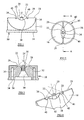
- a spray head 10 for a multiple fluid atomiser spray gun has a body 12 having a circular base 14 for mounting on a spray gun apparatus and sloping faces 16 leading to a narrow spray delivery face 18.
- the body 12 has a central passage 20 for delivery of coating fluid to a delivery nozzle 22 end part only and for delivery of atomising fluid though an annular orifice 24 surrounding the main fluid delivery nozzle.
- the nozzle 22 for the coating fluid protrudes beyond the spray face 18, which enables interaction of air and fluid streams beyond the spray face helping to inhibit atomised fluid droplets being picked up by air currents in the vicinity of the face.
- At the tip of the nozzle 22 its outer edge is chamfered at 23 to reduce a low pressure zone at the nozzle tip.
- Figure 5 of the drawings shows the zone of low pressure at 25.
- a conventional nozzle has a generally square tip, which creates a larger low pressure zone at the nozzle tip.
- the orifices 26, 28 are served by bores 30, 32 respectively, which are interconnected via an annular channel 34 in the base of the spray head.
- Annular wall 36, which separates the passage 20 from the channel 34 serves to locate the spray head relative to the spray gun apparatus.
- the spray head may be of metal or plastics material.
- a coating fluid is delivered via the nozzle 22 and air delivered through the annular orifice 24 atomises the coating fluid to create a spray plume, which is generally conical in shape (see particularly Figure 5 ).
- the spray pattern controlling fluid orifices 26, 28 deliver air from either side of the coating fluid spray plume to change the shape of the spray plume to being of generally oval section in order to control the area of delivery of the coating fluid.
- the coating fluid is applied to tablets in the pharmaceutical industry.
- the spray delivery face 18 is shaped in the region of the delivery nozzle 22 and the orifices 24, 26 and 28 in order to allow atomising air and spray pattern controlling air to drive droplets of main fluid from the region to inhibit bearding.
- the part of the face surrounding the annular orifice is dish shaped (38) and at opposite ends of the dish the face 40 slopes down to the spray shaping fluid orifices at 26 and 28. Smooth transitions between the dish 38 at opposite ends and the respective slopes 40 are shown at 42.
- the sides of the dish 38 and the sloping faces 40 are generally at less than 90° to the axes of their respective orifices, so that the air from those orifices tends to drive any droplets of the coating fluid from the delivery face in the region of the nozzle and orifices.
- the spray face 18 of the spray head is so profiled in the region of the main coating fluid nozzle, atomising fluid annulus and spray pattern controlling orifices that the escaping air is provided with a gradual geometrical enlargement as defined by the dish 38, slopes 40 and smooth transitions 42.
- the effect of the gradual geometrical enlargement is a gradual air release (as opposed to a sudden release) in that the air does not form recirculating eddy currents and thus little or no entrapment of coating fluid droplets back onto the spray face occurs.
- Figure 5 illustrates the atomising air plume 50 emitted from the annular orifice 24, the spray pattern controlling air plume 52 emitted from orifices 26 and 28 and the zone of interaction between both air plumes 50 and 52 to provide a combined air plume 54.
- the air streams shown as 50 and 52 keep the local external surfaces free from droplets, which would otherwise stick to the surfaces and cause bearding.
- Broken line 56 represents the typical shape of existing nozzle designs. Considering the likely shape of the air plumes as they emerge from orifices 26 and 28 it is probable that a low pressure zone is created in the region between these orifices and the annular orifice, which generates recirculating eddy currents in the air-flow, which entrain small droplets back onto the spray face adjacent to the orifices 24, 26 and 28.
- the invention eliminates this low pressure zone with solid material as shown at 58, which then through geometrical form provides a gradual geometrical enlargement which has the effect of eliminating the recirculating eddy currents normally produced with a face shown by the line 56.
- Figure 8 shows the sloping faces 16, which provide a path for spray plume replenishing air 60 to enter the vicinity of the orifices 24, 26 and 28 and replace air consumed by the air plumes 50 and 52.
- shallow angled faces illustrated by line 62 do not allow replenishing air 60 to enter the vicinity of the atomising and pattern air outlets akin to orifices 24, 26 and 28 creating low-pressure zones that result in bearding.
Landscapes
- Nozzles (AREA)
- Coating By Spraying Or Casting (AREA)
Abstract
Description
- This invention relates to spray gun heads.
- Multiple fluid atomiser spray guns are used for spaying fluid solutions in the food, agricultural, pharmaceutical and similar industries. Such spray guns generally have a spray delivery head that has a central nozzle for say a coating fluid, an orifice for introducing atomising air to the fluid to produce a spray plume and additional orifices for air to control the pattern of spray plume. Document
US6494387 discloses a spray head according to the preamble of claim 1. - In one known nozzle arrangement the atomising air orifice is an annulus surrounding a projecting fluid delivery nozzle and control fluid orifices are provided either side of the central nozzle in angled faces of the spray head, so that the central nozzle is in a trough.
- A drawback with this arrangement is that there is a tendency for droplets of the fluid to fall back and adhere to surfaces of the nozzle body, which is known as bearding. This droplet build up continues whilst spraying leading to a loss in nozzle performance including blockage. Furthermore, the build up of droplets can solidify and break off and fall into and contaminate the process. This results from the presence of low-pressure zones adj acent to the outlet orifices due to the sudden geometrical enlargement, through which the escaping air is emitted. These low-pressure zones generate recirculating eddy currents in the air flow, which entrain fluid droplets and deliver them onto the local external faces of the spray head adjacent to the orifices and annulus. Over time these droplets stick to each other forming the undesirable build up mainly in the nozzle region.
- It has been proposed to make the face of a spray gun nozzle completely flat but this does not prevent bearding.
- An object of this invention is to provide a spray nozzle for a multiple fluid spray gun, which at least reduces the effect of bearding.
- According to the invention a spray head for a multiple fluid atomiser spray gun has all the features of claim 1.
- Preferable embodiments of the inventon are defined by the dependent claims.
- Spray heads of the invention are preferably made of metal or of plastics material may be served to a spray gun by means of a locking collar or nut.
- This invention will now be further described, by way of example only, with reference to the accompanying drawings, in which:
-
Figure 1 is a side view of a spray nozzle according to the invention; -
Figure 2 is a plan view of the spray nozzle ofFigure 1 ; -
Figure 3 is a section on line AA ofFigure 2 ; -
Figure 4 shows the spray nozzle ofFigure 1 from above the side; -
Figure 5 is a sectional view of the spray nozzle ofFigure 1 showing spray patterns; -
Figure 6 is another side view of the spray nozzle ofFigure 1 ; -
Figure 7 is a view from below and one side of the spray nozzle ofFigure 1 ; and -
Figure 8 is an end view of the spray nozzle ofFigure 1 . - Referring to the accompanying drawings, a
spray head 10 for a multiple fluid atomiser spray gun has abody 12 having acircular base 14 for mounting on a spray gun apparatus and slopingfaces 16 leading to a narrowspray delivery face 18. - The
body 12 has acentral passage 20 for delivery of coating fluid to adelivery nozzle 22 end part only and for delivery of atomising fluid though anannular orifice 24 surrounding the main fluid delivery nozzle. Thenozzle 22 for the coating fluid protrudes beyond thespray face 18, which enables interaction of air and fluid streams beyond the spray face helping to inhibit atomised fluid droplets being picked up by air currents in the vicinity of the face. At the tip of thenozzle 22 its outer edge is chamfered at 23 to reduce a low pressure zone at the nozzle tip.Figure 5 of the drawings shows the zone of low pressure at 25. By contrast a conventional nozzle has a generally square tip, which creates a larger low pressure zone at the nozzle tip. On opposite sides of the delivery nozzle are spray pattern controllingfluid delivery orifices fluid delivery nozzle 22. Theorifices bores annular channel 34 in the base of the spray head.Annular wall 36, which separates thepassage 20 from thechannel 34 serves to locate the spray head relative to the spray gun apparatus. The spray head may be of metal or plastics material. - Through the spray head a coating fluid is delivered via the
nozzle 22 and air delivered through theannular orifice 24 atomises the coating fluid to create a spray plume, which is generally conical in shape (see particularlyFigure 5 ). However, the spray pattern controllingfluid orifices - The
spray delivery face 18 is shaped in the region of thedelivery nozzle 22 and theorifices - The part of the face surrounding the annular orifice is dish shaped (38) and at opposite ends of the dish the
face 40 slopes down to the spray shaping fluid orifices at 26 and 28. Smooth transitions between thedish 38 at opposite ends and therespective slopes 40 are shown at 42. The sides of thedish 38 and the sloping faces 40 are generally at less than 90° to the axes of their respective orifices, so that the air from those orifices tends to drive any droplets of the coating fluid from the delivery face in the region of the nozzle and orifices. - More specifically, the
spray face 18 of the spray head is so profiled in the region of the main coating fluid nozzle, atomising fluid annulus and spray pattern controlling orifices that the escaping air is provided with a gradual geometrical enlargement as defined by thedish 38, slopes 40 and smooth transitions 42. The effect of the gradual geometrical enlargement is a gradual air release (as opposed to a sudden release) in that the air does not form recirculating eddy currents and thus little or no entrapment of coating fluid droplets back onto the spray face occurs. -
Figure 5 illustrates the atomisingair plume 50 emitted from theannular orifice 24, the spray pattern controllingair plume 52 emitted fromorifices air plumes air plume 54. The air streams shown as 50 and 52 keep the local external surfaces free from droplets, which would otherwise stick to the surfaces and cause bearding. -
Broken line 56 represents the typical shape of existing nozzle designs. Considering the likely shape of the air plumes as they emerge fromorifices orifices line 56. -
Figure 8 shows the sloping faces 16, which provide a path for sprayplume replenishing air 60 to enter the vicinity of theorifices air plumes air 60 to enter the vicinity of the atomising and pattern air outlets akin toorifices
Claims (13)
- A spray head (10) for a multiple fluid atomiser spray gun comprising a spray delivery face (18) having a main fluid delivery nozzle (22) and an atomising fluid delivery orifice (24) associated therewith, the spray delivery face (18) being shaped to cause droplets of said main fluid to be driven away from the spray delivery face (18) by atomising fluid from the atomising flu.d delivery orifice (24), wherein
the main fluid delivery nozzle (22) is surrounded by the annular atomising fluid delivery orifice (24), characterised in that the spray delivery face surrounding this orifice is in the form of an elongate cavity (38) having a continuous surface from which the main fluid delivery nozzle (22) projects. - A spray head (10) as claimed in claim 1, wherein the main fluid delivery nozzle (22) projects beyond the annular orifice (24).
- A spray head (10) as claimed in claim 1 or 2, wherein the spray delivery face (18) outwardly of and adjacent to the atomising fluid delivery orifice (24) is at an angle of less than 90° to the axis of the orifice.
- A spray head (10) as claimed in any one of claims 1 to 3 having one or more orifices (26, 28) for delivery of spray pattern controlling fluid to shape the atomised fluid spray.
- A spray head (10) as claimed in claim 4, wherein the spray delivery face (18) is shaped to cause droplets of said main fluid to be driven away from the spray delivery face in the region of the spray pattern controlling fluid delivery orifice or orifices (26, 28).
- A spray head (10) as claimed in claim 5, wherein the or each shaping fluid delivery orifice (26, 28) has an axis at an angle to deliver its fluid across the main fluid atomised spray.
- A spray head (10) as claimed in claim 5 or 6, wherein the spray delivery face (18) inwards of the or each shaping fluid orifice (26, 28) is at an angle of less than 90° to the axis of the orifice.
- A spray head (10) as claimed in any one of claims 1 to 7 having it generally circular base (14) and a pair of opposed sloping sides (16) towards to the spray delivery face (18).
- A spray head (10) as claimed in any one of claims 1 to 8, having a generally central passage (20) leading to the main fluid delivery nozzle (22) and the associated atomising fluid delivery nozzle (24).
- A spray head (10) as claimed in any one of claims 4 to 9, wherein the or each spray pattern controlling fluid delivery orifices (26, 28) is supplied through its own bore (30, 32).
- A spray head (10) as claimed in claim 10, wherein, where more than one spray pattern controlling fluid delivery orifice (26, 28) is provided, their bores (30, 32) are interconnected.
- A spray head (10) as claimed in claim 11, wherein the bores (30, 32) are interconnected by means of an annular passage (34).
- A spray head (10) as claimed in any one of claims 1 to 12, wherein, at opposite ends of the elongate cavity (38), the delivery face (18) slopes down to a spray pattern controlling fluid delivery orifice (26, 28).
Applications Claiming Priority (2)
| Application Number | Priority Date | Filing Date | Title |
|---|---|---|---|
| GBGB0605105.6A GB0605105D0 (en) | 2006-03-14 | 2006-03-14 | Spray gun heads |
| PCT/GB2007/000871 WO2007104967A1 (en) | 2006-03-14 | 2007-03-14 | Spray gun heads |
Publications (2)
| Publication Number | Publication Date |
|---|---|
| EP2004331A1 EP2004331A1 (en) | 2008-12-24 |
| EP2004331B1 true EP2004331B1 (en) | 2011-08-03 |
Family
ID=36292718
Family Applications (1)
| Application Number | Title | Priority Date | Filing Date |
|---|---|---|---|
| EP07732013A Not-in-force EP2004331B1 (en) | 2006-03-14 | 2007-03-14 | Spray gun heads |
Country Status (4)
| Country | Link |
|---|---|
| EP (1) | EP2004331B1 (en) |
| AT (1) | ATE518601T1 (en) |
| GB (1) | GB0605105D0 (en) |
| WO (1) | WO2007104967A1 (en) |
Families Citing this family (8)
| Publication number | Priority date | Publication date | Assignee | Title |
|---|---|---|---|---|
| CN102355956A (en) | 2009-01-26 | 2012-02-15 | 3M创新有限公司 | Liquid Spray Guns, Gun Platforms, and Spray Head Assemblies |
| RU2571133C2 (en) | 2011-02-09 | 2015-12-20 | Зм Инновейтив Пропертиз Компани | Nozzle adapters and paint blower spraying head components |
| MX343152B (en) | 2011-07-28 | 2016-10-26 | 3M Innovative Properties Co | Spray head assembly with integrated air cap/nozzle for a liquid spray gun. |
| US9802211B2 (en) | 2011-10-12 | 2017-10-31 | 3M Innovative Properties Company | Spray head assemblies for liquid spray guns |
| RU2608490C9 (en) | 2012-03-06 | 2017-06-14 | 3М Инновейтив Пропертиз Компани | Sprayer with built-in pressure channel |
| EP2828000B1 (en) | 2012-03-23 | 2019-08-21 | 3M Innovative Properties Company | Spray gun barrel with inseparable nozzle |
| US10493473B2 (en) | 2013-07-15 | 2019-12-03 | 3M Innovative Properties Company | Air caps with face geometry inserts for liquid spray guns |
| GB201812072D0 (en) * | 2018-07-24 | 2018-09-05 | Carlisle Fluid Tech Uk Ltd | Spray gun nozzle |
Family Cites Families (6)
| Publication number | Priority date | Publication date | Assignee | Title |
|---|---|---|---|---|
| DE2924174C2 (en) * | 1979-06-15 | 1984-04-19 | Heinrich Bühnen KG Maschinenfabrik, Im- und Export, 2800 Bremen | Method and nozzle of a device for applying an adhesive to a substrate |
| AU4394399A (en) * | 1999-06-30 | 2001-01-22 | Anest Iwata Corporation | Low-pressure atomizing spray gun |
| SE524216C2 (en) * | 2001-12-14 | 2004-07-13 | Haakan Emilsson | Spray head with convex arched front shield with air nozzles |
| US20050173561A1 (en) * | 2002-05-28 | 2005-08-11 | John Cotter | Spray nozzle assembly |
| WO2004035222A2 (en) * | 2002-10-15 | 2004-04-29 | Spraying Systems, Co. | External mix air assisted spray nozzle assembly |
| DE102005034519A1 (en) * | 2005-07-20 | 2007-01-25 | J. Wagner Gmbh | applicator |
-
2006
- 2006-03-14 GB GBGB0605105.6A patent/GB0605105D0/en not_active Ceased
-
2007
- 2007-03-14 EP EP07732013A patent/EP2004331B1/en not_active Not-in-force
- 2007-03-14 AT AT07732013T patent/ATE518601T1/en not_active IP Right Cessation
- 2007-03-14 WO PCT/GB2007/000871 patent/WO2007104967A1/en not_active Ceased
Also Published As
| Publication number | Publication date |
|---|---|
| GB0605105D0 (en) | 2006-04-26 |
| EP2004331A1 (en) | 2008-12-24 |
| ATE518601T1 (en) | 2011-08-15 |
| WO2007104967A1 (en) | 2007-09-20 |
Similar Documents
| Publication | Publication Date | Title |
|---|---|---|
| EP2004331B1 (en) | Spray gun heads | |
| EP1596989B1 (en) | Air assisted spray nozzle assembly for spraying viscous liquids | |
| EP1108476B1 (en) | Low-pressure atomizing spray gun | |
| US10265723B2 (en) | Coating nozzle, coating apparatus, and coating method using the same | |
| CA2595876C (en) | A spray nozzle assembly | |
| EP2885083B1 (en) | Full cone air-assisted spray nozzle assembly | |
| RU2450867C2 (en) | Method and device for producing shaped elements with polyurethane layer | |
| EP0650766A2 (en) | Suction feed nozzle assembly for HVLP spray gun | |
| KR102279187B1 (en) | 2 Fluid Nozzle | |
| CN1397381A (en) | Spray gun | |
| CN101657265A (en) | Protective member and nozzle assembly configured to resist wear | |
| US11432555B2 (en) | Device and method for portioning a dough mass | |
| US4849049A (en) | Joining of dissimilar surfaces by quasi-random adhesive splatter pattern | |
| US20130032644A1 (en) | External mix air atomizing spray nozzle assembly | |
| CA2880592A1 (en) | Nozzle arrangement | |
| US20130112777A1 (en) | Spray coating system and method | |
| JP5336763B2 (en) | Spray gun for internal coating. | |
| CA2232619C (en) | A nozzle and a method for feeding thermosetting plastic | |
| CA2408384C (en) | External mixing nozzle | |
| US9346064B2 (en) | Radius edge bell cup and method for shaping an atomized spray pattern | |
| EP1844175B1 (en) | A thermal spraying method and device | |
| CN110843348B (en) | Spray painting device and spray painting system | |
| CN102143802A (en) | Coating apparatus and method | |
| SE524216C2 (en) | Spray head with convex arched front shield with air nozzles | |
| JPH0330853A (en) | Spray apparatus |
Legal Events
| Date | Code | Title | Description |
|---|---|---|---|
| PUAI | Public reference made under article 153(3) epc to a published international application that has entered the european phase |
Free format text: ORIGINAL CODE: 0009012 |
|
| 17P | Request for examination filed |
Effective date: 20081014 |
|
| AK | Designated contracting states |
Kind code of ref document: A1 Designated state(s): AT BE BG CH CY CZ DE DK EE ES FI FR GB GR HU IE IS IT LI LT LU LV MC MT NL PL PT RO SE SI SK TR |
|
| 17Q | First examination report despatched |
Effective date: 20090528 |
|
| GRAP | Despatch of communication of intention to grant a patent |
Free format text: ORIGINAL CODE: EPIDOSNIGR1 |
|
| GRAS | Grant fee paid |
Free format text: ORIGINAL CODE: EPIDOSNIGR3 |
|
| GRAA | (expected) grant |
Free format text: ORIGINAL CODE: 0009210 |
|
| AK | Designated contracting states |
Kind code of ref document: B1 Designated state(s): AT BE BG CH CY CZ DE DK EE ES FI FR GB GR HU IE IS IT LI LT LU LV MC MT NL PL PT RO SE SI SK TR |
|
| REG | Reference to a national code |
Ref country code: GB Ref legal event code: FG4D |
|
| REG | Reference to a national code |
Ref country code: CH Ref legal event code: EP |
|
| REG | Reference to a national code |
Ref country code: IE Ref legal event code: FG4D |
|
| REG | Reference to a national code |
Ref country code: DE Ref legal event code: R096 Ref document number: 602007016278 Country of ref document: DE Effective date: 20110929 |
|
| REG | Reference to a national code |
Ref country code: NL Ref legal event code: VDEP Effective date: 20110803 |
|
| LTIE | Lt: invalidation of european patent or patent extension |
Effective date: 20110803 |
|
| PG25 | Lapsed in a contracting state [announced via postgrant information from national office to epo] |
Ref country code: NL Free format text: LAPSE BECAUSE OF FAILURE TO SUBMIT A TRANSLATION OF THE DESCRIPTION OR TO PAY THE FEE WITHIN THE PRESCRIBED TIME-LIMIT Effective date: 20110803 Ref country code: FI Free format text: LAPSE BECAUSE OF FAILURE TO SUBMIT A TRANSLATION OF THE DESCRIPTION OR TO PAY THE FEE WITHIN THE PRESCRIBED TIME-LIMIT Effective date: 20110803 Ref country code: IS Free format text: LAPSE BECAUSE OF FAILURE TO SUBMIT A TRANSLATION OF THE DESCRIPTION OR TO PAY THE FEE WITHIN THE PRESCRIBED TIME-LIMIT Effective date: 20111203 Ref country code: PT Free format text: LAPSE BECAUSE OF FAILURE TO SUBMIT A TRANSLATION OF THE DESCRIPTION OR TO PAY THE FEE WITHIN THE PRESCRIBED TIME-LIMIT Effective date: 20111205 Ref country code: SE Free format text: LAPSE BECAUSE OF FAILURE TO SUBMIT A TRANSLATION OF THE DESCRIPTION OR TO PAY THE FEE WITHIN THE PRESCRIBED TIME-LIMIT Effective date: 20110803 Ref country code: LT Free format text: LAPSE BECAUSE OF FAILURE TO SUBMIT A TRANSLATION OF THE DESCRIPTION OR TO PAY THE FEE WITHIN THE PRESCRIBED TIME-LIMIT Effective date: 20110803 |
|
| REG | Reference to a national code |
Ref country code: AT Ref legal event code: MK05 Ref document number: 518601 Country of ref document: AT Kind code of ref document: T Effective date: 20110803 |
|
| PG25 | Lapsed in a contracting state [announced via postgrant information from national office to epo] |
Ref country code: PL Free format text: LAPSE BECAUSE OF FAILURE TO SUBMIT A TRANSLATION OF THE DESCRIPTION OR TO PAY THE FEE WITHIN THE PRESCRIBED TIME-LIMIT Effective date: 20110803 Ref country code: SI Free format text: LAPSE BECAUSE OF FAILURE TO SUBMIT A TRANSLATION OF THE DESCRIPTION OR TO PAY THE FEE WITHIN THE PRESCRIBED TIME-LIMIT Effective date: 20110803 Ref country code: LV Free format text: LAPSE BECAUSE OF FAILURE TO SUBMIT A TRANSLATION OF THE DESCRIPTION OR TO PAY THE FEE WITHIN THE PRESCRIBED TIME-LIMIT Effective date: 20110803 Ref country code: CY Free format text: LAPSE BECAUSE OF FAILURE TO SUBMIT A TRANSLATION OF THE DESCRIPTION OR TO PAY THE FEE WITHIN THE PRESCRIBED TIME-LIMIT Effective date: 20110803 Ref country code: AT Free format text: LAPSE BECAUSE OF FAILURE TO SUBMIT A TRANSLATION OF THE DESCRIPTION OR TO PAY THE FEE WITHIN THE PRESCRIBED TIME-LIMIT Effective date: 20110803 Ref country code: GR Free format text: LAPSE BECAUSE OF FAILURE TO SUBMIT A TRANSLATION OF THE DESCRIPTION OR TO PAY THE FEE WITHIN THE PRESCRIBED TIME-LIMIT Effective date: 20111104 |
|
| PG25 | Lapsed in a contracting state [announced via postgrant information from national office to epo] |
Ref country code: BE Free format text: LAPSE BECAUSE OF FAILURE TO SUBMIT A TRANSLATION OF THE DESCRIPTION OR TO PAY THE FEE WITHIN THE PRESCRIBED TIME-LIMIT Effective date: 20110803 |
|
| PG25 | Lapsed in a contracting state [announced via postgrant information from national office to epo] |
Ref country code: SK Free format text: LAPSE BECAUSE OF FAILURE TO SUBMIT A TRANSLATION OF THE DESCRIPTION OR TO PAY THE FEE WITHIN THE PRESCRIBED TIME-LIMIT Effective date: 20110803 Ref country code: CZ Free format text: LAPSE BECAUSE OF FAILURE TO SUBMIT A TRANSLATION OF THE DESCRIPTION OR TO PAY THE FEE WITHIN THE PRESCRIBED TIME-LIMIT Effective date: 20110803 |
|
| PG25 | Lapsed in a contracting state [announced via postgrant information from national office to epo] |
Ref country code: EE Free format text: LAPSE BECAUSE OF FAILURE TO SUBMIT A TRANSLATION OF THE DESCRIPTION OR TO PAY THE FEE WITHIN THE PRESCRIBED TIME-LIMIT Effective date: 20110803 Ref country code: RO Free format text: LAPSE BECAUSE OF FAILURE TO SUBMIT A TRANSLATION OF THE DESCRIPTION OR TO PAY THE FEE WITHIN THE PRESCRIBED TIME-LIMIT Effective date: 20110803 |
|
| PLBE | No opposition filed within time limit |
Free format text: ORIGINAL CODE: 0009261 |
|
| STAA | Information on the status of an ep patent application or granted ep patent |
Free format text: STATUS: NO OPPOSITION FILED WITHIN TIME LIMIT |
|
| PG25 | Lapsed in a contracting state [announced via postgrant information from national office to epo] |
Ref country code: DK Free format text: LAPSE BECAUSE OF FAILURE TO SUBMIT A TRANSLATION OF THE DESCRIPTION OR TO PAY THE FEE WITHIN THE PRESCRIBED TIME-LIMIT Effective date: 20110803 |
|
| 26N | No opposition filed |
Effective date: 20120504 |
|
| REG | Reference to a national code |
Ref country code: DE Ref legal event code: R097 Ref document number: 602007016278 Country of ref document: DE Effective date: 20120504 |
|
| PG25 | Lapsed in a contracting state [announced via postgrant information from national office to epo] |
Ref country code: MC Free format text: LAPSE BECAUSE OF NON-PAYMENT OF DUE FEES Effective date: 20120331 |
|
| REG | Reference to a national code |
Ref country code: CH Ref legal event code: PL |
|
| REG | Reference to a national code |
Ref country code: IE Ref legal event code: MM4A |
|
| PG25 | Lapsed in a contracting state [announced via postgrant information from national office to epo] |
Ref country code: IE Free format text: LAPSE BECAUSE OF NON-PAYMENT OF DUE FEES Effective date: 20120314 Ref country code: CH Free format text: LAPSE BECAUSE OF NON-PAYMENT OF DUE FEES Effective date: 20120331 Ref country code: LI Free format text: LAPSE BECAUSE OF NON-PAYMENT OF DUE FEES Effective date: 20120331 |
|
| PG25 | Lapsed in a contracting state [announced via postgrant information from national office to epo] |
Ref country code: ES Free format text: LAPSE BECAUSE OF FAILURE TO SUBMIT A TRANSLATION OF THE DESCRIPTION OR TO PAY THE FEE WITHIN THE PRESCRIBED TIME-LIMIT Effective date: 20111114 |
|
| PG25 | Lapsed in a contracting state [announced via postgrant information from national office to epo] |
Ref country code: BG Free format text: LAPSE BECAUSE OF FAILURE TO SUBMIT A TRANSLATION OF THE DESCRIPTION OR TO PAY THE FEE WITHIN THE PRESCRIBED TIME-LIMIT Effective date: 20111103 |
|
| PG25 | Lapsed in a contracting state [announced via postgrant information from national office to epo] |
Ref country code: MT Free format text: LAPSE BECAUSE OF FAILURE TO SUBMIT A TRANSLATION OF THE DESCRIPTION OR TO PAY THE FEE WITHIN THE PRESCRIBED TIME-LIMIT Effective date: 20110803 |
|
| REG | Reference to a national code |
Ref country code: DE Ref legal event code: R082 Ref document number: 602007016278 Country of ref document: DE |
|
| REG | Reference to a national code |
Ref country code: GB Ref legal event code: 732E Free format text: REGISTERED BETWEEN 20130905 AND 20130911 |
|
| REG | Reference to a national code |
Ref country code: DE Ref legal event code: R081 Ref document number: 602007016278 Country of ref document: DE Owner name: BOSCH PACKAGING TECHNOLOGY LTD., GB Free format text: FORMER OWNER: BWI PLC, PRESCOTE, GB Effective date: 20130826 Ref country code: DE Ref legal event code: R081 Ref document number: 602007016278 Country of ref document: DE Owner name: BOSCH PACKAGING TECHNOLOGY LTD., KNOWSLEY, GB Free format text: FORMER OWNER: BWI PLC, PRESCOTE, MERSEYSIDE L34 9JS, GB Effective date: 20130826 |
|
| REG | Reference to a national code |
Ref country code: FR Ref legal event code: TP Owner name: BOSCH PACKAGING TECHNOLOGY LIMITED, GB Effective date: 20131217 |
|
| PG25 | Lapsed in a contracting state [announced via postgrant information from national office to epo] |
Ref country code: TR Free format text: LAPSE BECAUSE OF FAILURE TO SUBMIT A TRANSLATION OF THE DESCRIPTION OR TO PAY THE FEE WITHIN THE PRESCRIBED TIME-LIMIT Effective date: 20110803 |
|
| PG25 | Lapsed in a contracting state [announced via postgrant information from national office to epo] |
Ref country code: LU Free format text: LAPSE BECAUSE OF NON-PAYMENT OF DUE FEES Effective date: 20120314 |
|
| PG25 | Lapsed in a contracting state [announced via postgrant information from national office to epo] |
Ref country code: HU Free format text: LAPSE BECAUSE OF FAILURE TO SUBMIT A TRANSLATION OF THE DESCRIPTION OR TO PAY THE FEE WITHIN THE PRESCRIBED TIME-LIMIT Effective date: 20070314 |
|
| REG | Reference to a national code |
Ref country code: FR Ref legal event code: PLFP Year of fee payment: 10 |
|
| REG | Reference to a national code |
Ref country code: FR Ref legal event code: PLFP Year of fee payment: 11 |
|
| REG | Reference to a national code |
Ref country code: FR Ref legal event code: PLFP Year of fee payment: 12 |
|
| REG | Reference to a national code |
Ref country code: DE Ref legal event code: R082 Ref document number: 602007016278 Country of ref document: DE Representative=s name: DREISS PATENTANWAELTE PARTG MBB, DE |
|
| REG | Reference to a national code |
Ref country code: DE Ref legal event code: R082 Ref document number: 602007016278 Country of ref document: DE Representative=s name: DREISS PATENTANWAELTE PARTG MBB, DE Ref country code: DE Ref legal event code: R081 Ref document number: 602007016278 Country of ref document: DE Owner name: HUETTLIN GMBH, DE Free format text: FORMER OWNER: BOSCH PACKAGING TECHNOLOGY LTD., KNOWSLEY, MERSEYSIDE, GB |
|
| REG | Reference to a national code |
Ref country code: GB Ref legal event code: 732E Free format text: REGISTERED BETWEEN 20210722 AND 20210728 |
|
| PGFP | Annual fee paid to national office [announced via postgrant information from national office to epo] |
Ref country code: FR Payment date: 20230320 Year of fee payment: 17 |
|
| PGFP | Annual fee paid to national office [announced via postgrant information from national office to epo] |
Ref country code: GB Payment date: 20230323 Year of fee payment: 17 Ref country code: DE Payment date: 20230320 Year of fee payment: 17 |
|
| PGFP | Annual fee paid to national office [announced via postgrant information from national office to epo] |
Ref country code: IT Payment date: 20230331 Year of fee payment: 17 |
|
| REG | Reference to a national code |
Ref country code: DE Ref legal event code: R119 Ref document number: 602007016278 Country of ref document: DE |
|
| GBPC | Gb: european patent ceased through non-payment of renewal fee |
Effective date: 20240314 |
|
| PG25 | Lapsed in a contracting state [announced via postgrant information from national office to epo] |
Ref country code: DE Free format text: LAPSE BECAUSE OF NON-PAYMENT OF DUE FEES Effective date: 20241001 |
|
| PG25 | Lapsed in a contracting state [announced via postgrant information from national office to epo] |
Ref country code: GB Free format text: LAPSE BECAUSE OF NON-PAYMENT OF DUE FEES Effective date: 20240314 |
|
| PG25 | Lapsed in a contracting state [announced via postgrant information from national office to epo] |
Ref country code: FR Free format text: LAPSE BECAUSE OF NON-PAYMENT OF DUE FEES Effective date: 20240331 |
|
| PG25 | Lapsed in a contracting state [announced via postgrant information from national office to epo] |
Ref country code: GB Free format text: LAPSE BECAUSE OF NON-PAYMENT OF DUE FEES Effective date: 20240314 Ref country code: FR Free format text: LAPSE BECAUSE OF NON-PAYMENT OF DUE FEES Effective date: 20240331 Ref country code: DE Free format text: LAPSE BECAUSE OF NON-PAYMENT OF DUE FEES Effective date: 20241001 |
|
| PG25 | Lapsed in a contracting state [announced via postgrant information from national office to epo] |
Ref country code: IT Free format text: LAPSE BECAUSE OF NON-PAYMENT OF DUE FEES Effective date: 20240314 |