EP2003961B1 - Bait dispensing system - Google Patents
Bait dispensing system Download PDFInfo
- Publication number
- EP2003961B1 EP2003961B1 EP06801535.3A EP06801535A EP2003961B1 EP 2003961 B1 EP2003961 B1 EP 2003961B1 EP 06801535 A EP06801535 A EP 06801535A EP 2003961 B1 EP2003961 B1 EP 2003961B1
- Authority
- EP
- European Patent Office
- Prior art keywords
- wheel member
- bait
- axle
- wheel
- cover portion
- Prior art date
- Legal status (The legal status is an assumption and is not a legal conclusion. Google has not performed a legal analysis and makes no representation as to the accuracy of the status listed.)
- Not-in-force
Links
Images


Classifications
-
- A—HUMAN NECESSITIES
- A01—AGRICULTURE; FORESTRY; ANIMAL HUSBANDRY; HUNTING; TRAPPING; FISHING
- A01M—CATCHING, TRAPPING OR SCARING OF ANIMALS; APPARATUS FOR THE DESTRUCTION OF NOXIOUS ANIMALS OR NOXIOUS PLANTS
- A01M25/00—Devices for dispensing poison for animals
- A01M25/002—Bait holders, i.e. stationary devices for holding poisonous bait at the disposal of the animal
- A01M25/004—Bait stations, i.e. boxes completely enclosing the bait and provided with animal entrances
-
- A—HUMAN NECESSITIES
- A01—AGRICULTURE; FORESTRY; ANIMAL HUSBANDRY; HUNTING; TRAPPING; FISHING
- A01M—CATCHING, TRAPPING OR SCARING OF ANIMALS; APPARATUS FOR THE DESTRUCTION OF NOXIOUS ANIMALS OR NOXIOUS PLANTS
- A01M25/00—Devices for dispensing poison for animals
-
- A—HUMAN NECESSITIES
- A01—AGRICULTURE; FORESTRY; ANIMAL HUSBANDRY; HUNTING; TRAPPING; FISHING
- A01M—CATCHING, TRAPPING OR SCARING OF ANIMALS; APPARATUS FOR THE DESTRUCTION OF NOXIOUS ANIMALS OR NOXIOUS PLANTS
- A01M25/00—Devices for dispensing poison for animals
- A01M25/002—Bait holders, i.e. stationary devices for holding poisonous bait at the disposal of the animal
-
- B—PERFORMING OPERATIONS; TRANSPORTING
- B65—CONVEYING; PACKING; STORING; HANDLING THIN OR FILAMENTARY MATERIAL
- B65F—GATHERING OR REMOVAL OF DOMESTIC OR LIKE REFUSE
- B65F1/00—Refuse receptacles; Accessories therefor
- B65F1/14—Other constructional features; Accessories
- B65F1/1468—Means for facilitating the transport of the receptacle, e.g. wheels, rolls
- B65F1/1473—Receptacles having wheels
-
- B—PERFORMING OPERATIONS; TRANSPORTING
- B65—CONVEYING; PACKING; STORING; HANDLING THIN OR FILAMENTARY MATERIAL
- B65F—GATHERING OR REMOVAL OF DOMESTIC OR LIKE REFUSE
- B65F2210/00—Equipment of refuse receptacles
- B65F2210/156—Mousetraps
Definitions
- the present invention relates generally to bait dispensers and, more particularly, to a mobile bait dispensing system for pests.
- a similar stationary trap is illustrated in United States Patent No. 6,739,087, issued on May 25, 2004 . It is intended to trap snails, slugs or the like. It has a flat base and a labyrinthine interior. A cover rests on top of the labyrinth, and the base of the trap is surrounded by a flange for the pests to crawl up on as they enter the interior of the trap where the bait is disposed.
- a disposable bait carrier is placed inside the base in such a manner that it is difficult to dislodge it if the base is moved.
- Patent No. 6,470,622 which issued on October 29, 2002 . That patent discloses a garbage container in the form of a large tub mounted on wheels. The upper portion of the tub is a compartment for garbage, while below the garbage compartment there is another compartment containing poisoned bait, which the rodents can access through entrance/exit holes in the wall of the container.
- the present invention addresses many of these needs, namely, the need for ease of portability as well as the need for safely dispensing a poison in a place where pests are naturally attracted anyway and in an unobtrusive, unnoticeable manner.
- a system for dispensing bait from a station is readily rolled from place to place and is easily accessible to small pests such as rodents, which are attracted to the station.
- the bait is inaccessible to non-target animals such as dogs or cats, and it is safely stored where children cannot get it and where it will not spill as the station is moved.
- a garbage (or other purpose) container mounted on wheels is used. At least one of the wheels is hollow and has an access port leading to the interior of the wheel where the bait is placed and maintained.
- a further example uses a garbage (or other purpose) container, which may be of either residential or commercial size.
- a wheel assembly supports the garbage storage member while it is standing still and as it is rolled from place to place on a relatively flat surface.
- In the wheel assembly there is a wheel member and an axle joining the wheel member to the garbage storage member.
- a bait holding station is located inside the inside the wheel member which is accessible to pests through a wall of the wheel member.
- One manner of constructing the wheel member includes making it in two principal parts, namely, an axle-engaging portion, which has an exterior surface facing outwardly from the wheel member and an interior surface facing inside the wheel member, and a cover portion, which overlies the interior surface of the axle-engaging portion. Together, the cover portion and the axle-engaging portion enclose a chamber between them inside the wheel member.
- a container for dispensing poisoned bait to pests has a garbage storage member and a wheel assembly supporting the storage member.
- the wheel assembly may provide support while the storage member is standing still and may also as the storage member is rolled from place to place.
- the wheel assembly includes a wheel member, an axle joining the wheel member to the garbage storage member, and a bait holding station inside the wheel member. The holding station is accessible to pests in an opening through a wall of the wheel member.
- a system comprising: means for maintaining a bait station separable from a rotationally mobile container in connection with said rotationally mobile container; means for securing bait in the bait station from spillage during motion of the rotationally mobile container; and means for accessing the bait.
- the above-described system includes means for protecting the bait from contamination.
- the above-described system includes means for concealing the bait station.
- the means for concealing the bait station includes: a wheel member; and a bait holding station disposed inside the wheel member accessible to pests through an opening into the wheel member.
- the above-described system includes: means for protecting the bait from contamination and means for concealing the bait station.
- the means for maintaining a bait station separable from a rotationally mobile container in connection with the rotationally mobile container of the above-described system includes: a wheel member; and a bait holding station disposed inside the wheel member accessible to pests through an opening of said wheel member.
- the means for maintaining a bait station separable from a rotationally mobile container in connection with the rotationally mobile container further includes: a storage member; and a wheel assembly supporting the storage member, the wheel assembly including: the wheel member; and an axle joining the wheel member to the storage member.
- the means for securing bait in the bait station from spillage during motion of the rotationally mobile container of the above-described system includes: an axle engaging portion having an exterior surface and an interior surface, the exterior surface facing outward from the container; a cover portion overlying the interior surface of the axle engaging portion of the wheel member; and a chamber disposed inside the wheel member between the axle engaging portion and the cover portion; wherein the axle engaging portion of the wheel member further includes a first track along the outer perimeter of the wheel member; the cover portion of the wheel member further includes a second track; and the second track is disposed in and rotationally moveable along the first track, thereby providing rotational mobility of the cover portion.
- the means for securing bait in the bait station from spillage during motion of the rotationally mobile container of the above-described system includes: a wheel member; a bait holding station disposed inside said wheel member; an entrance aperture disposed on said wheel member; and means to maintain said entrance aperture above the nadir of said wheel member.
- the means for accessing the bait of the above-described system includes: a wheel member; a bait holding station disposed inside said wheel member; and an entrance aperture disposed on said wheel member.
- the means for accessing the bait of the above-described system further includes ribs disposed inside the wheel member, thereby forming a passageway between the entrance aperture and the bait holding station.
- the means for accessing the bait further includes a labyrinthine interior, thereby forming a passageway between the entrance aperture and the bait holding station.
- a method comprising the steps of: maintaining a bait station separable from a rotationally mobile container in connection with said rotationally mobile container; securing bait in said bait station from spillage during motion of said rotationally mobile container; and providing access to the bait.
- the above-described method further includes the step of protecting the bait from contamination.
- the above-described method further includes the step of concealing said bait station.
- the above-described method further includes the steps of: protecting the bait from contamination; and concealing said bait station.
- a container for dispensing bait comprising: a storage member; and a wheel assembly supporting the storage member.
- the wheel assembly comprises: a wheel member; an axle joining the wheel member to the storage member; and a bait holding station disposed inside the wheel member accessible to pests through an opening into the wheel member.
- the wheel member of the above-described container includes a plurality of stalls for bait inside the wheel member.
- the above described container further includes: an axle engaging portion having an exterior surface and an interior surface, the exterior surface facing outward from the container; a cover portion overlying the interior surface of the axle engaging portion of the wheel member; and a chamber disposed inside the wheel member between the axle engaging portion and the cover portion.
- the axle-engaging portion of the wheel member further includes an entrance aperture leading to the chamber.
- the axle-engaging portion of the wheel member includes a first track along its outer perimeter, and the cover portion includes a second track disposed in and moveable along the first track as the cover portion is rotated.
- ribs are formed inside the cover portion, arranged to form passageways between the entrance aperture for the pests and the bait holding station, limiting access to the bait to the pests.
- the ribs are joined to the cover portion and provide support inside the wheel member for internally strengthening the cover portion.
- the entrance aperture for the pests through the axle-engaging portion of the wheel member is maintained above the nadir of the wheel member.
- the wheel member of the above described container includes a hub fixed on the axle engaging portion of the wheel member and a hub lock engaged on the hub and the axle, maintaining the position of the axle engaging portion of the wheel member on the axle during rotation of the cover portion of the wheel member.
- a stop is included on the garbage storage member, engaging the hub lock in a non-rotational engagement with the garbage storage member.
- the hub includes a sleeve portion extending outwardly from the axle engaging portion of the wheel member and having a central aperture arranged to receive the axle.
- the cover portion of the wheel member includes a socket arranged to receive an end portion of the axle inside the wheel member adjacent the sleeve portion of the hub.
- the cover portion of the wheel member of the above-described container includes a port extending through the cover portion and arranged to expose the bait holding station.
- the cover portion of the wheel member includes a cap engaged on edges of the port and closing the port.
- a lock is mounted on the cap arranged to maintain the cap in position closing the port.
- the cap includes means to unlock the cap, the unlocking means comprises a key tool.
- the bait holding station of the above-described container is formed to hold liquid bait.
- the bait holding station of the above-described container is formed to hold solid bait.
- an assembly for dispensing bait comprising: a hollow wheel member for a container, the hollow wheel member having an opening into the wheel member, and a bait holding station inside the hollow wheel member, the bait holding station accessible to the pests through the opening of the wheel member.
- the hollow wheel member includes a plurality of stalls for the bait inside the wheel member.
- the hollow wheel member includes an axle-engaging portion having an exterior surface and an interior surface.
- a cover portion overlies the interior surface of the axle-engaging portion and encloses a chamber inside the wheel member between the axle engaging portion and the cover portion.
- the axle-engaging portion is provided with an entrance aperture for the pests leading to the chamber.
- ribs formed inside the cover portion are arranged to form passageways between the entrance aperture for the pests and the bait station and limit access to the bait to the pests.
- the ribs are joined to the cover portion and arranged to provide support inside the wheel member for internally strengthening the cover portion.
- the hollow wheel member of the above-described assembly includes a hub fixed on the axle engaging portion of the wheel member, and a hub lock engaged on the hub and disposed to maintain the position of the wheel member on an axle during rotation of the wheel member.
- the hub includes a sleeve portion extending outwardly from the axle engaging portion of the wheel member and having a central aperture arranged to receive an axle.
- the cover portion of the wheel member includes a socket arranged to receive an end portion of an axle inside the wheel member adjacent the sleeve portion of the hub.
- the cover portion of the wheel member includes a port extending through the cover portion and arranged to expose the bait holding station.
- the cover portion of the wheel member includes a cap engaged upon edges of the port and disposed in a position closing the port.
- a lock is mounted on the cap maintaining the cap in a position closing the port.
- the lock is opened using a key tool.
- the cover portion of the above-described assembly includes locking members arranged to engage the cover portion on the axle-engaging portion.
- the locking members are affixed to and moveable with the cover portion for selectively engaging the locking members and the cover portion into a fixed position on the axle engaging portion.
- a wrench socket is provided in the cover portion and arranged to connect a wrench to the cover portion, whereby torque from the wrench may be transmitted to the cover portion and the locking members.
- the bait station of the above-described assembly is mounted inside the axle-engaging portion.
- the bait holding station of the above-described assembly is formed to hold liquid bait.
- the bait holding station of the above-described assembly is formed to hold solid bait.
- the bait used may be toxic or nontoxic.
- the bait used may be a poison, used for monitoring, or used for tracking.
- the bait may include pheromones or radioisotopes.
- system may be used as a monitoring, tracking, or trapping system for targeted pests.
- garbage container 74 hub lock 12 garbage storage member 76 fingers 14 wheel assembly 78 rectangular plate 16 plot 80 wheel well 18 wheel member 82 wall portion 20 axle 84 port 22 bait holding station 86 cap 24 pests 88 disk-shaped member 26 entrance aperture 90 teeth 28 axle-engaging portion 92 ledges 30 cover portion 94 lock-operating member 32 exterior surface 96 engagement dimples 32' exterior surface 98 wrench-type tool 34 interior surface 100 prongs 38 track 38 118 wheel member 40 second track, track 40 130 axle-engaging portion 42 tread surface 132 interior surface 44 distal end portion 134 cover portion 46 socket 136 locking members 48 clamp 48 138 lip 50 seat 140 tool 52 ribs 141 latch 54 interior surface of wheel member 18 142 entrance apertures 56 passageways 144 bait stations 58 bait block 146 rib members 58A liquid bait 148 stalls 60 bait holding pin 150 tread surface 62 hub 152 axle receiving sleeve 64 sleeve portion 66 centrally apertured portion 68
- FIGS. 1-11 illustrate examples of the bait dispensing system to produce various aspects of the present invention, though these particular embodiments are illustrated and described herein only for exemplary purposes. Moreover, variations of the system and methods of utilizing the same will become apparent to those of ordinary skill in the relevant structural and mechanical arts upon reading the following disclosure. Thus, the present invention is not to be considered limited to only the structures, systems, and methods described herein.
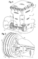
- Fig. 1 is a perspective view of a garbage container 10, which can be rolled from place to place with a poisoned bait station in each of its wheels.
- Garbage container 10 includes a garbage storage member 12 and a wheel assembly 14. Wheel assembly 14 supports storage member 12 such that container 10 may be rolled from place to place on a relatively flat surface, such as plot 16, and is also supported while container 10 is standing still.
- Wheel assembly 14 includes at least one wheel member 18 with an axle 20 joining wheel member 18 to garbage storage member 12.
- a bait holding station 22 is located inside wheel member 18. While the container 10, as illustrated in Fig. 1 , has a pair of wheel members like wheel member 18, there may be more wheel members, or fewer, to support the container 10.
- wheel well 80 is illustrated for reference. Locating a bait holding station inside a wheel member provides a means for maintaining a bait station that is separate from, but kept in connection with, its rolling container.
- Fig. 2 is an enlarged perspective view of a portion of garbage container 10, wheel assembly 14, as circled in Fig. 1.
- Fig. 2 further illustrates a portion of a pest 24 entering wheel member 18.
- Pests 24 may enter the interior of wheel member 18 through an entrance aperture 26 formed in a wall of the wheel member, such as the axle-engaging portion 28 of wheel member 18.
- Wheel member 18 also includes a cover portion 30, which overlies and engages the axle engaging portion 28, forming a chamber inside wheel member 18 between axle engaging portion 28 and the cover portion 30.
- Wheel well 80 is illustrated for reference.
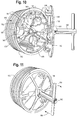
- Fig. 3 is an enlarged exploded view in perspective of one of the container wheels shown in Fig. 1 , illustrating a means for concealing the bait station.
- Fig. 3 particularly shows the exterior surface 32 facing outwardly from wheel member 18 and the interior surface 34 of axle engaging portion 28 facing inside of the wheel member 18.
- Cover portion 30 overlies the interior surface 34 to form and enclose the chamber between axle engaging portion 28 and the cover portion 30.
- Bait holding stations 22 are disposed on interior surface 34 of axle engaging portion 28.
- Bait holding pin 60 connects to bait holding station 22.
- Bait block 58 attaches to bait holding pin 60.
- Entrance aperture 26 is formed in the wall of wheel member 18, interior surface 34.
- Port 84 is formed exterior surface 32, providing access to the interior of wheel member 18.
- a cap 86 covers or otherwise encloses port 84.
- Disk-shaped member 88 is attached to cap 86. Teeth 90 on disk-shaped member 88 serve as a means to lock cap 86 in place.
- Fig. 4 is an exploded view of the garbage container wheel shown in Fig. 3.
- Fig. 4 particularly shows the interior surface 54 of wheel member 18 and the exterior surface 32' of axle engaging portion 28 facing outwardly from of wheel member 18.
- Hub 62 forms a portion of the exterior surface 32.
- Hub 62 includes a sleeve portion 64 and a centrally apertured portion 66.
- Hub lock 74 attaches around hub 62.
- the interior of wheel member 18 includes an axle receiving socket 46 and fins 52, which form passageways 56.
- the internal side of cap 86, disk-shaped member 88 and teeth 90 are illustrated for reference.
- Fig. 3A is a perspective view of a modified part of the garbage container wheel shown in Fig. 3 , and including a tool for operating the part.
- the external side of cap 86 includes a recessed lock-operating member 94.
- Indented engagement dimples 96 are disposed on lock-operating member 94.
- Prongs 100 on a wrench-type tool 98 fit engagement dimples 96.
- Fig. 4A is a perspective view of the container wheel shown in Fig. 4 partially assembled. Entrance aperture 26 is illustrated for reference. Fingers 76 on one end of hub lock 74 surround fns 73. A rectangular plate 78 is disposed on the other end of hub lock 74. A first track 38 encircles the perimeter of axle-engaging portion 28. A second track 40 encircles the interior of the outer perimeter of cover portion 30. Liquid bait 58A is disposed in the interior of the wheel.
- Fig. 5 is an exploded sectional view of the garbage container wheel shown in Fig. 3 .
- Fig. 6 is a sectional view of the container wheel shown in Fig. 5 showing the elements of the wheel after being assembled.
- Figs. 5 and 6 along with Figs. 3 and 4 , illustrate how axle-engaging portion 28 engages cover portion 30 of wheel member 18.
- Axle-engaging portion 28, as will be explained hereafter, remains in a non-rotational attitude on axle 20, while cover portion 30 is constructed to rotate on axle 20 and axle-engaging portion 28.
- Such rotation is accomplished by forming complementary track members 38 and 40 on axle-engaging portion 28 and cover portion 30.
- the examples shown here illustrate various means for securing the bait from spillage during motion of the container.
- First track 38 is located along the outer perimeter of axle-engaging portion 28.
- a complementary second track 40 is formed along the outer perimeter of cover portion 30.
- Second track 40 is disposed in and moves along first track 38 as cover portion 30 is rotated.
- the outer surface of cover portion 30 includes a tread surface 42, which contacts the flat surface of plot 16.
- tread surface 42 is advanced, rotating cover portion 30 and moving second track 40 along first track 38.
- Distal end portion 44 of axle 20 is nested in socket 46 (illustrated in Fig. 6 ) formed inside the cover portion 30 and is maintained there by a clamp 48 or similar locking means engaged on axle 20.
- Clamp 48 also slides rotationally on a seat 50 formed in the cover portion 30, thus keeping second track 40 in constant engagement with first track 38.
- Ribs 52 provide a series of connecting stalls and form passageways 56 between the entrance aperture 26 and the bait holding station 22.
- the tortuous course of the passageways can readily be traversed by a pest, but access to bait block 58 in bait holding station 22 is limited to the pests which are targeted by this invention, and access to non-targeted animals and children is denied.
- cover portion 30 In addition to providing passageways between the entrance aperture and the bait station, or to a plurality of bait stations if the interior of the chamber is so designed, ribs 52, when firmly joined to cover portion 30, provide internal strength to the cover portion.
- the internal structural design of cover portion 30 may be designed to hold a solid bait in block form, such as bait block 58 impaled on a bait holding pin 60, or be arranged, alternatively, to utilize granulated bait sprinkled in place or held in a bag.
- a liquid bait may be used such as bait 58A (as illustrated in Fig. 4A ).
- axle-engaging portion 28 of wheel member 18 is non-rotationally mounted on axle 20, entrance aperture 26 can be maintained above the nadir of wheel member 18. Consequently, bait specimens, either in crumb form or liquid remains, coming to rest on the bottom of the wheel's internal chamber do not fall out and do not become available to non-targeted subjects.
- Axle engaging portion 28 includes a hub 62 fixed in the center of the axle-engaging portion.
- a sleeve portion 64 of hub 62 extends outwardly from axle-engaging portion 28 and includes a centrally apertured portion 66 arranged to receive axle 20, permitting axle 20 to rotate in the aperture.
- Sleeve portion 64 does not rotate.
- Axle 20 extends through sleeve portion 64 and into cover portion 30, ending inside socket 46 where the distal end 44 of axle 30 is held.
- a stabilizing sleeve 68 or similar device may be formed inside the cover portion 30 of wheel member 18 to support cover portion 30 further on the portion of axle 20 adjacent to distal end 44 of axle 20.
- a clamp 70 similar to clamp 48, is mounted on axle 20 adjacent to outer end 72 of sleeve portion 64.
- Clamp 70 prevents sleeve portion 64 and hub 62 from moving along axle 20 away from cover portion 30, thereby maintaining first track 38 of axle engaging portion 28 fully engaged upon, and slideable in, second track 40 of cover portion 30.
- sleeve portion 64 of the hub includes one or more fins 73, which are fixed between sleeve portion 64 and exterior surface 32 of axle engaging portion 28.
- a hub lock 74 that is mounted on axle 20 includes a tubular center portion surrounding axle 20 and a first end, which engages fins 73 with fingers 76. Fingers 76 prevent fins 73 from turning around axle 20 independently from hub lock 74.
- a second end of hub lock 74 is provided with a rectangular plate 78, which is fixed to the tubular center portion of hub lock 74 and moveable only along with the tubular center portion and fingers 76. Hub lock 74 thus controls rotation of axle engaging portion 28 of wheel assembly 18 as fingers 76 are engaged on fins 73.
- Axle engaging portion 28 and hub lock 74 can only rotate on axle 20 as a unit.
- Fig. 7 is an enlarged sectional view of the circled portion of the wheel shown in Fig. 6 .
- Cap 86 is provided with a rotating disk-shaped member 88 with teeth 90 to engage ledges 92 formed in the cover member 30 along the edges of port 84.
- the external side of cap 86 includes a recessed lock-operating member 94, which is designed to be difficult to operate without a specially adapted tool.
- Fig. 7A is a sectional view of the wheel shown in Fig. 5 taken along the line 7A - 7A in Fig. 5 and showing a locking mechanism in a closed position. Teeth 90 of rotating disk-shaped member 88 engage ledges 92 of cover portion 30. Port 84, Cap 86, ribs 52, and bait block 58 are illustrated for reference.
- Fig. 7B is an identical sectional view of the wheel shown in Fig. 7A except showing the locking mechanism in an open position. Teeth 90 of rotating disk-shaped member 88 are rotated away from ledges 92 of cover portion 30. Arrow 101 illustrates the rotation. Port 84, Cap 86, ribs 52, and bait block 58 are illustrated for reference.
- Fig. 8 is an enlarged elevational view of the second of the two garbage container wheels shown in Fig. 1 .
- Port 84 on exterior surface 32 exposes bait block 58.
- Wheel well 80 is illustrated for reference.
- port 84 is formed in cover portion 30.
- the bait inside the chamber may be readily supplemented, or new bait supplied.
- cap 86 for port 84 may be locked in place to keep the port closed, or unlocked in order to open the port and service the bait station.
- cap 86 is provided with a rotating disk-shaped member 88 with teeth 90 to engage ledges 92 formed in the cover member 30 along the edges of port 84.
- the external side of cap 86 includes recessed lock-operating member 94, which is designed to be difficult to operate without a specially adapted tool.
- Member 94 utilizes outwardly facing indented engagement dimples 96 which must be grasped by using a wrench-type tool 98 having prongs 100 that fit the dimples.
- Engaging prongs 100 in dimples 96 and then twisting tool 98 releases teeth 90 of cap 86 from ledges 92 and permits a service person to withdraw cap 86 from port 84.
- Cap 86 and its associated lock-operating member 94 maintain the cap 86 in position closing port 84 when teeth 90 are engaged with ledges 92, thereby keeping non-targeted animals and unauthorized persons from reaching the bait.
- Fig. 9 is a sectional view of the garbage container wheel shown in Fig. 8 and also showing the mounting of the wheel on the container.
- plate 78 on hub lock 74 is mounted on axle 20 in wheel well 80 of garbage storage member 12 adjacent to a wall portion 82 of the storage member. Plate 78 engages wall portion 82 before plate 78 can accomplish any substantial amount of rotation. Wall portion 82 therefore acts as a stop member for hub lock 74, preventing the hub lock 72 from rotating around axle 20. Since hub lock 72 and axle-engaging portion 28 turn as a unit, axle-engaging portion 28 is also prevented from rotating around axle 20.
- a hub lock may be used to prevent axle engaging portion 28 from rotating, but it will be noted, particularly from Fig. 9 , that when the form of hub lock and its related assembly just described are used, clamp 70 and hub lock 74 cooperate not only in fixing axle engaging portion 28 of wheel member 18 in non-rotational engagement on axle 20, but the hub lock engagement on fins 73 also maintains the position of axle engaging portion 28 of wheel member 18 on the axle 20 during rotation of the cover portion 30 as garbage container 10 is moved from place to place.
- FIG. 10 is a perspective view, partly disassembled, of an alternative example of the garbage container wheels shown in Fig 1 .
- Fig. 11 is a perspective view of the garbage container wheel, assembled, shown in Fig. 10 .
- a labyrinthine chamber interior surface 132 on axle-engaging portion 130 forms bait holding stations inside a wheel member 118.
- a cover portion 134 overlies interior surface 132 to complete the chamber.
- Cover portion 134 includes locking members 136 which engage cover portion 134 onto axle engaging portion 130 by moving locking members 136 of cover portion 134 under a lip 138 adjacent the inside perimeter of axle-engaging portion 130.
- a special wrench like tool 140 is utilized to operate a latch 141 inside the chamber and unlock cover portion 134 in order to remove it from axle-engaging portion 130.
- Entrance apertures 142 are provided in axle-engaging portion 130 for admitting targeted pests into wheel member 118.
- Bait stations 144 are located adjacent to rib members 146 in stalls 148 inside the internal chamber of wheel member 118. Rib members 146 also support and strengthen tread surface 150 of axle-engaging portion 130 of wheel member 118. It will be noted that in the example of Figs. 10 and 11 axle engaging portion 130 and cover portion 134 utilize an axle receiving sleeve 152 in the center of axle engaging portion 130 as the basis for rotating as a unit on an axle of a garbage container.
- various examples of the invention may offer one or more of the following objects or advantages, illustrating industrial applicability.
- One object is to provide a bait station, which can be readily moved from a storage location to a collection site, intercepting rodents or other pests as they appear.
- Another object is to provide a bait station, which is readily serviceable.
- Another object is to provide a bait station, which is readily accessible to pests but not readily accessible to children, non-targeted pets, and non-targeted wildlife.
- Another object is to provide a bait station, which is associated with a garbage canister, which attracts pests but does not expose the poisoned bait to the personnel who pick up and empty the garbage container.
- Another object is to provide a bait station, which attracts pests for the purpose of monitoring and tracking pest prevalence.
Description
- The present invention relates generally to bait dispensers and, more particularly, to a mobile bait dispensing system for pests.
- Various bait stations have previously been advanced for dispensing poisoned bait to rodents and similar pests. One, which is illustrated in United States Patent No.
6,807,768, issued on October 26, 2004 , consists of a molded plastic base containing a labyrinthine interior where blocks of solid poisoned bait are mounted. The base is set down on a relatively flat surface where it stays, and the rodents come there to feed. The base is covered by a lid, which is fastened closed by a latch. Feet are provided on the underside of the base in order to raise it above the surface upon which it was set and prevent moisture from entering the bait chambers. - A similar stationary trap is illustrated in United States Patent No.
6,739,087, issued on May 25, 2004 . It is intended to trap snails, slugs or the like. It has a flat base and a labyrinthine interior. A cover rests on top of the labyrinth, and the base of the trap is surrounded by a flange for the pests to crawl up on as they enter the interior of the trap where the bait is disposed. - Another flat-based station is shown in United States Patent No.
6,789,352 . A disposable bait carrier is placed inside the base in such a manner that it is difficult to dislodge it if the base is moved. - Other stations hang, as illustrated in United States Patent No.
5,522,172, issued June 4, 1996 , and some are contained in trays which roll on casters for supporting various objects in an insect-free environment, as illustrated in United States Patent No.5,440,833 for example. A combined bait station and garbage can support is disclosed in United States Patent No.3,488,879 , illustrating a support held in place by a spike driven through the base plate of the station into a surface, such as earth or pavement, below the support - A further combination of a garbage can and bait station is shown in United States
- Patent No.
6,470,622 which issued on October 29, 2002 . That patent discloses a garbage container in the form of a large tub mounted on wheels. The upper portion of the tub is a compartment for garbage, while below the garbage compartment there is another compartment containing poisoned bait, which the rodents can access through entrance/exit holes in the wall of the container. - The variety of the foregoing structures and their relatively recent appearance suggest that more convenient and improved poisoned bait dispensing systems are needed. The present invention addresses many of these needs, namely, the need for ease of portability as well as the need for safely dispensing a poison in a place where pests are naturally attracted anyway and in an unobtrusive, unnoticeable manner.
- According to one example of the invention, a system for dispensing bait from a station is readily rolled from place to place and is easily accessible to small pests such as rodents, which are attracted to the station. The bait is inaccessible to non-target animals such as dogs or cats, and it is safely stored where children cannot get it and where it will not spill as the station is moved.
- In a more particular example of the invention, a garbage (or other purpose) container mounted on wheels is used. At least one of the wheels is hollow and has an access port leading to the interior of the wheel where the bait is placed and maintained.
- A further example uses a garbage (or other purpose) container, which may be of either residential or commercial size. A wheel assembly supports the garbage storage member while it is standing still and as it is rolled from place to place on a relatively flat surface. In the wheel assembly there is a wheel member and an axle joining the wheel member to the garbage storage member. A bait holding station is located inside the inside the wheel member which is accessible to pests through a wall of the wheel member. One manner of constructing the wheel member includes making it in two principal parts, namely, an axle-engaging portion, which has an exterior surface facing outwardly from the wheel member and an interior surface facing inside the wheel member, and a cover portion, which overlies the interior surface of the axle-engaging portion. Together, the cover portion and the axle-engaging portion enclose a chamber between them inside the wheel member.
- According to another example of the invention, there is provided a container for dispensing poisoned bait to pests. The garbage container has a garbage storage member and a wheel assembly supporting the storage member. The wheel assembly may provide support while the storage member is standing still and may also as the storage member is rolled from place to place. The wheel assembly includes a wheel member, an axle joining the wheel member to the garbage storage member, and a bait holding station inside the wheel member. The holding station is accessible to pests in an opening through a wall of the wheel member.
- In these and further examples of the invention, it will be apparent that means are provided for placing a bait station in close proximity to a pest attraction, making it possible to do so without additional effort, making the placement of the overall container typically unnoticeable to passersby, and does so in a consistently safe way.
- According to one set of examples of the present invention, there is provided a system comprising: means for maintaining a bait station separable from a rotationally mobile container in connection with said rotationally mobile container; means for securing bait in the bait station from spillage during motion of the rotationally mobile container; and means for accessing the bait.
- In another example, the above-described system includes means for protecting the bait from contamination.
- In another example, the above-described system includes means for concealing the bait station. In a further example, the means for concealing the bait station includes: a wheel member; and a bait holding station disposed inside the wheel member accessible to pests through an opening into the wheel member.
- In another example, the above-described system includes: means for protecting the bait from contamination and means for concealing the bait station.
- In another example, the means for maintaining a bait station separable from a rotationally mobile container in connection with the rotationally mobile container of the above-described system includes: a wheel member; and a bait holding station disposed inside the wheel member accessible to pests through an opening of said wheel member. In a further example, the means for maintaining a bait station separable from a rotationally mobile container in connection with the rotationally mobile container further includes: a storage member; and a wheel assembly supporting the storage member, the wheel assembly including: the wheel member; and an axle joining the wheel member to the storage member.
- In another example, the means for securing bait in the bait station from spillage during motion of the rotationally mobile container of the above-described system includes: an axle engaging portion having an exterior surface and an interior surface, the exterior surface facing outward from the container; a cover portion overlying the interior surface of the axle engaging portion of the wheel member; and a chamber disposed inside the wheel member between the axle engaging portion and the cover portion; wherein the axle engaging portion of the wheel member further includes a first track along the outer perimeter of the wheel member; the cover portion of the wheel member further includes a second track; and the second track is disposed in and rotationally moveable along the first track, thereby providing rotational mobility of the cover portion.
- In another example, the means for securing bait in the bait station from spillage during motion of the rotationally mobile container of the above-described system includes: a wheel member; a bait holding station disposed inside said wheel member; an entrance aperture disposed on said wheel member; and means to maintain said entrance aperture above the nadir of said wheel member.
- In another example, the means for accessing the bait of the above-described system includes: a wheel member; a bait holding station disposed inside said wheel member; and an entrance aperture disposed on said wheel member.
- In another example, the means for accessing the bait of the above-described system further includes ribs disposed inside the wheel member, thereby forming a passageway between the entrance aperture and the bait holding station. In a further example, the means for accessing the bait further includes a labyrinthine interior, thereby forming a passageway between the entrance aperture and the bait holding station.
- According to another set of examples of the present invention, there is provided a method comprising the steps of: maintaining a bait station separable from a rotationally mobile container in connection with said rotationally mobile container; securing bait in said bait station from spillage during motion of said rotationally mobile container; and providing access to the bait.
- In another example, the above-described method further includes the step of protecting the bait from contamination.
- In another example, the above-described method further includes the step of concealing said bait station.
- In another example, the above-described method further includes the steps of: protecting the bait from contamination; and concealing said bait station.
- According to another set of examples of the present invention, there is provided a container for dispensing bait comprising: a storage member; and a wheel assembly supporting the storage member. The wheel assembly comprises: a wheel member; an axle joining the wheel member to the storage member; and a bait holding station disposed inside the wheel member accessible to pests through an opening into the wheel member.
- In another example, the wheel member of the above-described container includes a plurality of stalls for bait inside the wheel member.
- In another example, the above described container further includes: an axle engaging portion having an exterior surface and an interior surface, the exterior surface facing outward from the container; a cover portion overlying the interior surface of the axle engaging portion of the wheel member; and a chamber disposed inside the wheel member between the axle engaging portion and the cover portion. In a further example, the axle-engaging portion of the wheel member further includes an entrance aperture leading to the chamber. In a further example, the axle-engaging portion of the wheel member includes a first track along its outer perimeter, and the cover portion includes a second track disposed in and moveable along the first track as the cover portion is rotated. In a further example, ribs are formed inside the cover portion, arranged to form passageways between the entrance aperture for the pests and the bait holding station, limiting access to the bait to the pests. In a further example, the ribs are joined to the cover portion and provide support inside the wheel member for internally strengthening the cover portion. In a further example, the entrance aperture for the pests through the axle-engaging portion of the wheel member is maintained above the nadir of the wheel member.
- In another example, the wheel member of the above described container includes a hub fixed on the axle engaging portion of the wheel member and a hub lock engaged on the hub and the axle, maintaining the position of the axle engaging portion of the wheel member on the axle during rotation of the cover portion of the wheel member. In a further example, a stop is included on the garbage storage member, engaging the hub lock in a non-rotational engagement with the garbage storage member. In a further example, the hub includes a sleeve portion extending outwardly from the axle engaging portion of the wheel member and having a central aperture arranged to receive the axle. In a further example, the cover portion of the wheel member includes a socket arranged to receive an end portion of the axle inside the wheel member adjacent the sleeve portion of the hub.
- In another example, the cover portion of the wheel member of the above-described container includes a port extending through the cover portion and arranged to expose the bait holding station. In a further example, the cover portion of the wheel member includes a cap engaged on edges of the port and closing the port. In a further example, a lock is mounted on the cap arranged to maintain the cap in position closing the port. In a further example, the cap includes means to unlock the cap, the unlocking means comprises a key tool.
- In another example, the bait holding station of the above-described container is formed to hold liquid bait.
- In another example, the bait holding station of the above-described container is formed to hold solid bait.
- According to another set of examples of the present invention, there is provided an assembly for dispensing bait comprising: a hollow wheel member for a container, the hollow wheel member having an opening into the wheel member, and a bait holding station inside the hollow wheel member, the bait holding station accessible to the pests through the opening of the wheel member.
- In a further example of the above-described assembly, the hollow wheel member includes a plurality of stalls for the bait inside the wheel member.
- In a further example of the above-described assembly, the hollow wheel member includes an axle-engaging portion having an exterior surface and an interior surface. A cover portion overlies the interior surface of the axle-engaging portion and encloses a chamber inside the wheel member between the axle engaging portion and the cover portion. In a further example, the axle-engaging portion is provided with an entrance aperture for the pests leading to the chamber. In a further example, ribs formed inside the cover portion are arranged to form passageways between the entrance aperture for the pests and the bait station and limit access to the bait to the pests. In a further example, the ribs are joined to the cover portion and arranged to provide support inside the wheel member for internally strengthening the cover portion.
- In a further example, the hollow wheel member of the above-described assembly includes a hub fixed on the axle engaging portion of the wheel member, and a hub lock engaged on the hub and disposed to maintain the position of the wheel member on an axle during rotation of the wheel member. In a further example, the hub includes a sleeve portion extending outwardly from the axle engaging portion of the wheel member and having a central aperture arranged to receive an axle. In a further example, the cover portion of the wheel member includes a socket arranged to receive an end portion of an axle inside the wheel member adjacent the sleeve portion of the hub. In a further example, the cover portion of the wheel member includes a port extending through the cover portion and arranged to expose the bait holding station. In a further example, the cover portion of the wheel member includes a cap engaged upon edges of the port and disposed in a position closing the port. In a further example, a lock is mounted on the cap maintaining the cap in a position closing the port. In a further example, the lock is opened using a key tool.
- In another example, the cover portion of the above-described assembly includes locking members arranged to engage the cover portion on the axle-engaging portion. In a further example, the locking members are affixed to and moveable with the cover portion for selectively engaging the locking members and the cover portion into a fixed position on the axle engaging portion. In a further example, a wrench socket is provided in the cover portion and arranged to connect a wrench to the cover portion, whereby torque from the wrench may be transmitted to the cover portion and the locking members.
- In a further example, the bait station of the above-described assembly is mounted inside the axle-engaging portion.
- In another example, the bait holding station of the above-described assembly is formed to hold liquid bait.
- In another example, the bait holding station of the above-described assembly is formed to hold solid bait.
- In further examples of the present invention, the bait used may be toxic or nontoxic. The bait used may be a poison, used for monitoring, or used for tracking. The bait may include pheromones or radioisotopes.
- In further examples of the present invention, the system may be used as a monitoring, tracking, or trapping system for targeted pests.
- Other objects and features of the examples of this invention will be apparent to those persons who are skilled in the practical art of designing and using various forms of bait stations as well as to those persons who are particularly skilled in applying methods of pest control in populated areas, especially after an examination of the following description of the examples of the present invention and of the accompanying drawings.
- From all of the foregoing it will be evident that, although particular forms of the invention have been illustrated and described, nevertheless various modifications can be made without departing from the true spirit and scope of the invention.
- The present invention and its advantages will be better understood by referring to the following detailed description and the attached drawings in which:
-
Fig. 1 is a perspective view of a garbage container, which can be rolled from place to place with a poisoned bait station in each of its wheels; -
Fig. 2 is an enlarged perspective view of a portion of the garbage container circled inFig. 1 , and also showing a portion of a pest entering one of the container's wheels; -
Fig. 3 is an enlarged exploded view in perspective of one of the container wheels shown inFig. 1 ; -
Fig.3A is a perspective view of a modified part of the garbage container wheel shown inFig. 3 , and including a tool for operating the part; -
Fig. 4 is an exploded view of the garbage container wheel shown inFig.3 ; -
Fig. 4A is a perspective view of the container wheel shown inFig. 4 partially assembled; -
Fig. 5 is an exploded sectional view of the garbage container wheel shown inFig. 3 ; -
Fig. 6 is a sectional view of the container wheel shown inFig. 5 showing the elements of the wheel after being assembled; -
Fig. 7 is an enlarged sectional view of the circled portion of the wheel shown inFig. 6 ; -
Fig. 7A is a sectional view of the wheel shown inFig. 5 taken along theline 7A - 7A inFig. 5 and showing a locking mechanism in a closed position; -
Fig. 7B is an identical sectional view of the wheel shown inFig. 7A except showing the locking mechanism in an open position; -
Fig. 8 is an enlarged elevational view of the second of the two garbage container wheels shown inFig. 1 ; -
Fig. 9 is a sectional view of the garbage container wheel shown inFig. 8 and also showing the mounting of the wheel on the container; -
Fig. 10 is a perspective view, partly disassembled, of an alternative example of the garbage container wheels shown inFig 1 ; and -
Fig. 11 is a perspective view of the garbage container wheel, assembled, shown inFig. 10 . - The following elements are numbered as described in the drawings and detailed description of the invention:
10 garbage container 74 hub lock 12 garbage storage member 76 fingers 14 wheel assembly 78 rectangular plate 16 plot 80 wheel well 18 wheel member 82 wall portion 20 axle 84 port 22 bait holding station 86 cap 24 pests 88 disk-shaped member 26 entrance aperture 90 teeth 28 axle-engaging portion 92 ledges 30 cover portion 94 lock-operating member 32 exterior surface 96 engagement dimples 32' exterior surface 98 wrench- type tool 34 interior surface 100 prongs 38 track 38118 wheel member 40 second track, track 40 130 axle-engaging portion 42 tread surface 132 interior surface 44 distal end portion 134 cover portion 46 socket 136 locking members 48 clamp 48138 lip 50 seat 140 tool 52 ribs 141 latch 54 interior surface of wheel member 18142 entrance apertures 56 passageways 144 bait stations 58 bait block 146 rib members 58A liquid bait 148 stalls 60 bait holding pin 150 tread surface 62 hub 152 axle receiving sleeve 64 sleeve portion 66 centrally apertured portion 68 stabilizing sleeve 70 clamp 72 outer end of sleeve portion 6473 fins - Each of
Figs. 1-11 illustrate examples of the bait dispensing system to produce various aspects of the present invention, though these particular embodiments are illustrated and described herein only for exemplary purposes. Moreover, variations of the system and methods of utilizing the same will become apparent to those of ordinary skill in the relevant structural and mechanical arts upon reading the following disclosure. Thus, the present invention is not to be considered limited to only the structures, systems, and methods described herein. -
Fig. 1 is a perspective view of agarbage container 10, which can be rolled from place to place with a poisoned bait station in each of its wheels. Although a container for holding garbage is illustrated in this example, the purpose or use of the container is not critical to operation of the invention.Garbage container 10 includes agarbage storage member 12 and awheel assembly 14.Wheel assembly 14supports storage member 12 such thatcontainer 10 may be rolled from place to place on a relatively flat surface, such asplot 16, and is also supported whilecontainer 10 is standing still. -
Wheel assembly 14 includes at least onewheel member 18 with anaxle 20 joiningwheel member 18 togarbage storage member 12. As will be illustrated inFig. 3 , abait holding station 22 is located insidewheel member 18. While thecontainer 10, as illustrated inFig. 1 , has a pair of wheel members likewheel member 18, there may be more wheel members, or fewer, to support thecontainer 10. Incidentally, wheel well 80 is illustrated for reference. Locating a bait holding station inside a wheel member provides a means for maintaining a bait station that is separate from, but kept in connection with, its rolling container. -
Fig. 2 is an enlarged perspective view of a portion ofgarbage container 10,wheel assembly 14, as circled inFig. 1. Fig. 2 further illustrates a portion of apest 24entering wheel member 18.Pests 24 may enter the interior ofwheel member 18 through anentrance aperture 26 formed in a wall of the wheel member, such as the axle-engagingportion 28 ofwheel member 18.Wheel member 18 also includes acover portion 30, which overlies and engages theaxle engaging portion 28, forming a chamber insidewheel member 18 betweenaxle engaging portion 28 and thecover portion 30.Wheel well 80 is illustrated for reference. -
Fig. 3 is an enlarged exploded view in perspective of one of the container wheels shown inFig. 1 , illustrating a means for concealing the bait station.Fig. 3 particularly shows theexterior surface 32 facing outwardly fromwheel member 18 and theinterior surface 34 ofaxle engaging portion 28 facing inside of thewheel member 18.Cover portion 30 overlies theinterior surface 34 to form and enclose the chamber betweenaxle engaging portion 28 and thecover portion 30. - Other elements are illustrated which will be detailed further in the following figures, providing means for protecting the bait from contamination while providing means for accessing the bait. Bait holding
stations 22 are disposed oninterior surface 34 ofaxle engaging portion 28. Bait holdingpin 60 connects to bait holdingstation 22.Bait block 58 attaches to bait holdingpin 60.Entrance aperture 26 is formed in the wall ofwheel member 18,interior surface 34.Port 84 is formedexterior surface 32, providing access to the interior ofwheel member 18. Acap 86 covers or otherwise enclosesport 84. Disk-shapedmember 88 is attached to cap 86.Teeth 90 on disk-shapedmember 88 serve as a means to lockcap 86 in place. -
Fig. 4 is an exploded view of the garbage container wheel shown inFig. 3. Fig. 4 particularly shows theinterior surface 54 ofwheel member 18 and the exterior surface 32' ofaxle engaging portion 28 facing outwardly from ofwheel member 18. - Other elements are illustrated which will be detailed further in the following figures.
Hub 62 forms a portion of theexterior surface 32.Hub 62 includes asleeve portion 64 and a centrallyapertured portion 66.Hub lock 74 attaches aroundhub 62. The interior ofwheel member 18 includes anaxle receiving socket 46 andfins 52, which formpassageways 56. The internal side ofcap 86, disk-shapedmember 88 andteeth 90 are illustrated for reference. -
Fig. 3A is a perspective view of a modified part of the garbage container wheel shown inFig. 3 , and including a tool for operating the part. The external side ofcap 86 includes a recessed lock-operatingmember 94. Indented engagement dimples 96 are disposed on lock-operatingmember 94.Prongs 100 on a wrench-type tool 98 fit engagement dimples 96. -
Fig. 4A is a perspective view of the container wheel shown inFig. 4 partially assembled.Entrance aperture 26 is illustrated for reference.Fingers 76 on one end ofhub lock 74surround fns 73. Arectangular plate 78 is disposed on the other end ofhub lock 74. Afirst track 38 encircles the perimeter of axle-engagingportion 28. Asecond track 40 encircles the interior of the outer perimeter ofcover portion 30.Liquid bait 58A is disposed in the interior of the wheel. -
Fig. 5 is an exploded sectional view of the garbage container wheel shown inFig. 3 .Fig. 6 is a sectional view of the container wheel shown inFig. 5 showing the elements of the wheel after being assembled.Figs. 5 and 6 , along withFigs. 3 and 4 , illustrate how axle-engagingportion 28 engagescover portion 30 ofwheel member 18. Axle-engagingportion 28, as will be explained hereafter, remains in a non-rotational attitude onaxle 20, whilecover portion 30 is constructed to rotate onaxle 20 and axle-engagingportion 28. Such rotation is accomplished by formingcomplementary track members portion 28 andcover portion 30. The examples shown here illustrate various means for securing the bait from spillage during motion of the container. -
First track 38 is located along the outer perimeter of axle-engagingportion 28. A complementarysecond track 40 is formed along the outer perimeter ofcover portion 30.Second track 40 is disposed in and moves alongfirst track 38 ascover portion 30 is rotated. The outer surface ofcover portion 30 includes atread surface 42, which contacts the flat surface ofplot 16. Whencontainer 10 is pushed across the surface ofplot 16, supported on the wheel assembly,tread surface 42 is advanced,rotating cover portion 30 and movingsecond track 40 alongfirst track 38.Distal end portion 44 ofaxle 20 is nested in socket 46 (illustrated inFig. 6 ) formed inside thecover portion 30 and is maintained there by aclamp 48 or similar locking means engaged onaxle 20.Clamp 48 also slides rotationally on a seat 50 formed in thecover portion 30, thus keepingsecond track 40 in constant engagement withfirst track 38. - Various means may be used to control access to the bait. Inside the chamber formed by axle-engaging
portion 28 andcover portion 30,several ribs 52 are arranged oncover portion 30.Ribs 52 provide a series of connecting stalls andform passageways 56 between theentrance aperture 26 and thebait holding station 22. The tortuous course of the passageways can readily be traversed by a pest, but access tobait block 58 inbait holding station 22 is limited to the pests which are targeted by this invention, and access to non-targeted animals and children is denied. - In addition to providing passageways between the entrance aperture and the bait station, or to a plurality of bait stations if the interior of the chamber is so designed,
ribs 52, when firmly joined to coverportion 30, provide internal strength to the cover portion. The internal structural design ofcover portion 30 may be designed to hold a solid bait in block form, such asbait block 58 impaled on abait holding pin 60, or be arranged, alternatively, to utilize granulated bait sprinkled in place or held in a bag. Similarly, a liquid bait may be used such asbait 58A (as illustrated inFig. 4A ). - Since axle-engaging
portion 28 ofwheel member 18 is non-rotationally mounted onaxle 20,entrance aperture 26 can be maintained above the nadir ofwheel member 18. Consequently, bait specimens, either in crumb form or liquid remains, coming to rest on the bottom of the wheel's internal chamber do not fall out and do not become available to non-targeted subjects. -
Axle engaging portion 28 includes ahub 62 fixed in the center of the axle-engaging portion. Asleeve portion 64 ofhub 62 extends outwardly from axle-engagingportion 28 and includes a centrallyapertured portion 66 arranged to receiveaxle 20, permittingaxle 20 to rotate in the aperture.Sleeve portion 64 does not rotate.Axle 20 extends throughsleeve portion 64 and intocover portion 30, ending insidesocket 46 where thedistal end 44 ofaxle 30 is held. If desired, a stabilizingsleeve 68 or similar device may be formed inside thecover portion 30 ofwheel member 18 to supportcover portion 30 further on the portion ofaxle 20 adjacent todistal end 44 ofaxle 20. - A
clamp 70, similar to clamp 48, is mounted onaxle 20 adjacent toouter end 72 ofsleeve portion 64.Clamp 70 preventssleeve portion 64 andhub 62 from moving alongaxle 20 away fromcover portion 30, thereby maintainingfirst track 38 ofaxle engaging portion 28 fully engaged upon, and slideable in,second track 40 ofcover portion 30. - In order to keep axle-engaging
portion 28 from rotating onaxle 20,sleeve portion 64 of the hub includes one ormore fins 73, which are fixed betweensleeve portion 64 andexterior surface 32 ofaxle engaging portion 28. Ahub lock 74 that is mounted onaxle 20 includes a tubular centerportion surrounding axle 20 and a first end, which engagesfins 73 withfingers 76.Fingers 76 preventfins 73 from turning aroundaxle 20 independently fromhub lock 74. A second end ofhub lock 74 is provided with arectangular plate 78, which is fixed to the tubular center portion ofhub lock 74 and moveable only along with the tubular center portion andfingers 76.Hub lock 74 thus controls rotation ofaxle engaging portion 28 ofwheel assembly 18 asfingers 76 are engaged onfins 73.Axle engaging portion 28 and hub lock 74 can only rotate onaxle 20 as a unit. -
Fig. 7 is an enlarged sectional view of the circled portion of the wheel shown inFig. 6 .Cap 86 is provided with a rotating disk-shapedmember 88 withteeth 90 to engageledges 92 formed in thecover member 30 along the edges ofport 84. The external side ofcap 86 includes a recessed lock-operatingmember 94, which is designed to be difficult to operate without a specially adapted tool. -
Fig. 7A is a sectional view of the wheel shown inFig. 5 taken along theline 7A - 7A inFig. 5 and showing a locking mechanism in a closed position.Teeth 90 of rotating disk-shapedmember 88 engageledges 92 ofcover portion 30.Port 84,Cap 86,ribs 52, andbait block 58 are illustrated for reference. -
Fig. 7B is an identical sectional view of the wheel shown inFig. 7A except showing the locking mechanism in an open position.Teeth 90 of rotating disk-shapedmember 88 are rotated away fromledges 92 ofcover portion 30.Arrow 101 illustrates the rotation.Port 84,Cap 86,ribs 52, andbait block 58 are illustrated for reference. -
Fig. 8 is an enlarged elevational view of the second of the two garbage container wheels shown inFig. 1 .Port 84 onexterior surface 32 exposesbait block 58.Wheel well 80 is illustrated for reference. - In order to access
bait holding station 22 and replenishsolid bait 58 orliquid bait 58A stored therein,port 84 is formed incover portion 30. When the port is opened and rotated over thebait station 22, the bait inside the chamber may be readily supplemented, or new bait supplied. As also illustrated inFigs. 3 and3A , cap 86 forport 84 may be locked in place to keep the port closed, or unlocked in order to open the port and service the bait station. Preferably,cap 86 is provided with a rotating disk-shapedmember 88 withteeth 90 to engageledges 92 formed in thecover member 30 along the edges ofport 84. Preferably, also, the external side ofcap 86 includes recessed lock-operatingmember 94, which is designed to be difficult to operate without a specially adapted tool.Member 94 utilizes outwardly facing indented engagement dimples 96 which must be grasped by using a wrench-type tool 98 havingprongs 100 that fit the dimples. Engagingprongs 100 indimples 96 and then twistingtool 98releases teeth 90 ofcap 86 fromledges 92 and permits a service person to withdrawcap 86 fromport 84.Cap 86 and its associated lock-operatingmember 94 maintain thecap 86 inposition closing port 84 whenteeth 90 are engaged withledges 92, thereby keeping non-targeted animals and unauthorized persons from reaching the bait. -
Fig. 9 is a sectional view of the garbage container wheel shown inFig. 8 and also showing the mounting of the wheel on the container. As shown inFig. 9 ,plate 78 onhub lock 74 is mounted onaxle 20 in wheel well 80 ofgarbage storage member 12 adjacent to awall portion 82 of the storage member.Plate 78 engageswall portion 82 beforeplate 78 can accomplish any substantial amount of rotation.Wall portion 82 therefore acts as a stop member forhub lock 74, preventing thehub lock 72 from rotating aroundaxle 20. Sincehub lock 72 and axle-engagingportion 28 turn as a unit, axle-engagingportion 28 is also prevented from rotating aroundaxle 20. - Other forms of a hub lock may be used to prevent
axle engaging portion 28 from rotating, but it will be noted, particularly fromFig. 9 , that when the form of hub lock and its related assembly just described are used, clamp 70 and hub lock 74 cooperate not only in fixingaxle engaging portion 28 ofwheel member 18 in non-rotational engagement onaxle 20, but the hub lock engagement onfins 73 also maintains the position ofaxle engaging portion 28 ofwheel member 18 on theaxle 20 during rotation of thecover portion 30 asgarbage container 10 is moved from place to place. - An alternative form of
wheel member 118 for a garbage container is illustrated inFigs. 10 and 11. Fig. 10 is a perspective view, partly disassembled, of an alternative example of the garbage container wheels shown inFig 1 .Fig. 11 is a perspective view of the garbage container wheel, assembled, shown inFig. 10 . - A labyrinthine chamber
interior surface 132 on axle-engagingportion 130 forms bait holding stations inside awheel member 118. Acover portion 134 overliesinterior surface 132 to complete the chamber.Cover portion 134 includes lockingmembers 136 which engagecover portion 134 ontoaxle engaging portion 130 by moving lockingmembers 136 ofcover portion 134 under alip 138 adjacent the inside perimeter of axle-engagingportion 130. In this example, a special wrench liketool 140 is utilized to operate alatch 141 inside the chamber and unlockcover portion 134 in order to remove it from axle-engagingportion 130. -
Entrance apertures 142 are provided in axle-engagingportion 130 for admitting targeted pests intowheel member 118.Bait stations 144 are located adjacent torib members 146 installs 148 inside the internal chamber ofwheel member 118.Rib members 146 also support and strengthentread surface 150 of axle-engagingportion 130 ofwheel member 118. It will be noted that in the example ofFigs. 10 and 11 axle engaging portion 130 andcover portion 134 utilize anaxle receiving sleeve 152 in the center ofaxle engaging portion 130 as the basis for rotating as a unit on an axle of a garbage container. - Although the description above contains many specifications, these should not be construed as limiting the scope of the invention but as merely providing illustrations of some of the presently preferred embodiments of this present invention. Persons skilled in the art will understand that the method and apparatus described herein may be practiced, including but not limited to, by the embodiments described. Further, it should be understood that the invention is not to be unduly limited to the foregoing which has been set forth for illustrative purposes. Various modifications and alternatives will be apparent to those skilled in the art without departing from the true scope of the invention, as defined in the following claims.
- Accordingly, various examples of the invention may offer one or more of the following objects or advantages, illustrating industrial applicability.
- One object is to provide a bait station, which can be readily moved from a storage location to a collection site, intercepting rodents or other pests as they appear.
- Another object is to provide a bait station, which is readily serviceable.
- Another object is to provide a bait station, which is readily accessible to pests but not readily accessible to children, non-targeted pets, and non-targeted wildlife.
- Another object is to provide a bait station, which is associated with a garbage canister, which attracts pests but does not expose the poisoned bait to the personnel who pick up and empty the garbage container.
- Another object is to provide a bait station, which attracts pests for the purpose of monitoring and tracking pest prevalence.
Claims (15)
- A system comprising:means for maintaining a bait station separable from a rotationally mobile container (10) in connection with said rotationally mobile container (10);means for securing bait in said bait station from spillage during motion of said rotationally mobile container (10);means for accessing the bait; anda wheel member (18)characterised in comprising:a bait holding station (22) disposed inside said wheel member (18) accessible to pests through an opening into said wheel member (18).
- The system of claim 1 further comprising:means for protecting the bait from contamination.
- The system of either of claims 1 or 2 further comprising:means for concealing said bait holding station (22).
- The system of any preceding claim, comprising:a storage member (12); anda wheel assembly (14) supporting said storage member (12), the wheel assembly comprising:said wheel member (18); andan axle (20) joining said wheel member (18) to said storage member (12).
- The system of any preceding claim, wherein said wheel member (18) comprises:an entrance aperture (26) disposed on said wheel member (18); andmeans to maintain said entrance aperture (26) above the nadir of said wheel member (18).
- The system of claim 5, further comprising ribs (52) or a labyrinthine interior disposed inside said wheel member (18), thereby forming a passageway (56) between said entrance aperture (26) and said bait holding station (22).
- The system of any preceding claim, wherein said wheel member (18) comprises a plurality of stalls inside said wheel member (18).
- The system of claim 7, wherein said wheel member (18) comprises:an axle engaging portion (28, 130) having an exterior surface (32, 32') and an interior surface (34), said exterior surface (32, 32') facing outward from the container (10);a cover portion (30, 134) overlying said interior surface (34) of said axle engaging portion (28, 130) of said wheel member (18); anda chamber disposed inside said wheel member (18) between said axle engaging portion (28, 130) and said cover portion (30, 134).
- The system of claim 8, wherein said axle engaging portion (28, 130) of said wheel member (18) further comprises an entrance aperture (26) leading to said chamber.
- The system of claim 8 or 9, wherein:said axle engaging portion (28, 130) of said wheel member (18) further comprises:a first track (38) along the outer perimeter of said wheel member (18);said cover portion (30, 134) of said wheel member (18) further comprises a second track (40); andsaid second track (40) is disposed in and rotationally moveable along said first track (38), thereby providing rotational mobility of said cover portion (30, 134).
- The system of any of claims 8 to 10, wherein said cover portion (30, 134) further comprises ribs (52) formed inside said cover portion (30, 134) arranged to form a passageway (56) between said entrance aperture (26) for the pests and said bait holding station (22), thereby limiting access to the bait.
- The system of claim 11, wherein said ribs (52) are joined to said cover portion (30), thereby providing support inside said wheel member (18) for internally strengthening said cover portion (30, 134).
- The system of any of claims 8 to 12, wherein said wheel member (18) comprises:a hub (62) fixed on said axle engaging portion (28, 130) of said wheel member (18); anda hub lock (74) engaged on said hub (62) and said axle (20), thereby maintaining the position of said axle engaging portion (28, 130) of said wheel member (18) on said axle during rotation of said cover portion (30, 134) of said wheel member (18);preferably said storage member (12) further comprising a stop engaging said hub lock in a non-rotational engagement with said storage member.
- The system of claim 13, wherein said hub (62) comprises:a sleeve portion (64) extending outwardly from said axle engaging portion (28, 130) of said wheel member (18); anda central aperture arranged to receive said axle (20);preferably said cover portion (30, 134) of said wheel member (18) comprising a socket (46) arranged to receive an end portion of said axle (20) inside said wheel member (18) adjacent said sleeve portion (64) of said hub (62).
- The system of any of claims 8 to 14, wherein said cover portion (30, 134) of said wheel member (18) comprises a port (84) extending through said cover portion (30, 134) and arranged to expose said bait holding station (22).
Applications Claiming Priority (2)
| Application Number | Priority Date | Filing Date | Title |
|---|---|---|---|
| US78183906P | 2006-03-13 | 2006-03-13 | |
| PCT/US2006/031848 WO2007108821A2 (en) | 2006-03-13 | 2006-08-16 | Bait dispensing system |
Publications (3)
| Publication Number | Publication Date |
|---|---|
| EP2003961A2 EP2003961A2 (en) | 2008-12-24 |
| EP2003961A4 EP2003961A4 (en) | 2013-12-11 |
| EP2003961B1 true EP2003961B1 (en) | 2015-01-14 |
Family
ID=38522858
Family Applications (1)
| Application Number | Title | Priority Date | Filing Date |
|---|---|---|---|
| EP06801535.3A Not-in-force EP2003961B1 (en) | 2006-03-13 | 2006-08-16 | Bait dispensing system |
Country Status (4)
| Country | Link |
|---|---|
| US (2) | US8490324B2 (en) |
| EP (1) | EP2003961B1 (en) |
| CA (1) | CA2681087C (en) |
| WO (1) | WO2007108821A2 (en) |
Families Citing this family (15)
| Publication number | Priority date | Publication date | Assignee | Title |
|---|---|---|---|---|
| CA2681087C (en) * | 2006-03-13 | 2015-01-27 | R C Solutions Inc. | Bait dispensing system |
| US7987629B2 (en) * | 2007-09-28 | 2011-08-02 | Technicide, Inc. | Rodent bait station |
| AU2010100265B4 (en) * | 2010-03-22 | 2010-11-04 | Brisbane City Council | Rodent Baiting Station |
| US8701336B2 (en) * | 2010-08-12 | 2014-04-22 | Daniel J. Kay | Pest control device |
| US9451761B2 (en) * | 2011-01-28 | 2016-09-27 | James D. Messina | Pest management system |
| US20150342171A1 (en) * | 2014-05-30 | 2015-12-03 | Steffen Seyss | Trash Can Trap |
| USD787658S1 (en) | 2015-04-15 | 2017-05-23 | Frank M. Civale | Combination odor absorber and pest deterrent |
| US10098336B2 (en) * | 2015-08-31 | 2018-10-16 | Dennis Darnell | Insect trap for a garbage receptacle |
| US11076578B2 (en) * | 2016-04-19 | 2021-08-03 | Us Biologic, Inc. | Time release application and monitoring system |
| US11730161B2 (en) * | 2016-04-19 | 2023-08-22 | Us Biologic Inc. | Time release application and monitoring system configured to prevent untargeted wildlife entry or disruption |
| USD891003S1 (en) * | 2019-01-18 | 2020-07-21 | All Seasons Feeders, Ltd. | Conversion system |
| MX2020009119A (en) * | 2020-09-02 | 2022-03-03 | Bernal Ricardo Alvarado | Carousel type insect trap. |
| CN113508798B (en) * | 2021-08-09 | 2022-12-27 | 广州隆昇科技有限公司 | Bait agent feeding device and control method |
| US11812737B1 (en) * | 2022-08-03 | 2023-11-14 | Darren Mark Teren | Wearable protection device for residential and commercial trash cans and method of use |
| US11672245B1 (en) * | 2022-08-03 | 2023-06-13 | Darren Mark Teren | Pest control device for residential trash cans and method of use |
Family Cites Families (72)
| Publication number | Priority date | Publication date | Assignee | Title |
|---|---|---|---|---|
| US759030A (en) * | 1903-02-07 | 1904-05-03 | John Wilson Sheaffer | Insect-trap. |
| US1223873A (en) * | 1914-06-29 | 1917-04-24 | Cicero W Hartt | Garbage-receptacle and trap. |
| US1223525A (en) * | 1915-11-05 | 1917-04-24 | Harry Schallman | Combined garbage-can and rat-trap. |
| US1350402A (en) * | 1916-12-04 | 1920-08-24 | Cereghino Louis Joseph | Combined flytrap and garbage-can |
| US1472476A (en) * | 1921-08-11 | 1923-10-30 | Kendzierski Joseph | Waste trap |
| US1815595A (en) * | 1929-12-31 | 1931-07-21 | Arthur E Simpson | Insect control device |
| US1955496A (en) * | 1930-06-03 | 1934-04-17 | Parley F Harris | Pedestal block trap |
| US1960464A (en) * | 1932-06-13 | 1934-05-29 | Acme White Lead | Ant trap |
| US1994859A (en) * | 1933-03-27 | 1935-03-19 | Langum Conrad | Fly-poisoning device |
| US2252812A (en) * | 1940-02-17 | 1941-08-19 | Wallace C Mcanlis | Combined garbage receptacle and rat trap |
| US2297193A (en) * | 1940-03-02 | 1942-09-29 | Silverman Samuel | Garbage can holder |
| US2356022A (en) * | 1943-12-06 | 1944-08-15 | Eddie G Wright | Insect trap |
| US2492957A (en) * | 1947-09-17 | 1950-01-03 | Joseph N Blair | Animal trap |
| US3098703A (en) * | 1959-08-04 | 1963-07-23 | Gilbert G Reuter Company | Apparatus and method for insect control |
| US3321863A (en) * | 1965-07-13 | 1967-05-30 | Jr Allen B Maxam | Model car wheel mounting |
| US3427743A (en) * | 1968-02-21 | 1969-02-18 | Robert F Brunner | Insect bait dispenser |
| US3488879A (en) * | 1968-04-29 | 1970-01-13 | Timothy E Laughlin | Combined poison bait station and garbage can support |
| US3661326A (en) * | 1970-01-07 | 1972-05-09 | Milton A Wilson | Insecticide and repellant holder for attachment to garbage can lid |
| US3704539A (en) * | 1971-10-12 | 1972-12-05 | Bernard V Alvarez | Poison bait station for small bugs or the like |
| US3772820A (en) * | 1972-03-20 | 1973-11-20 | H Bond | Bait station for slugs, snails and the like |
| US4043685A (en) * | 1974-10-22 | 1977-08-23 | Vic-Tree (Mouldings) Limited | Fasteners |
| US4194690A (en) * | 1978-04-25 | 1980-03-25 | Stever Carole A | Bug-bopper |
| US4208829A (en) * | 1978-06-12 | 1980-06-24 | Rocon Industries, Inc. | Bait station |
| FR2435199A1 (en) * | 1978-06-30 | 1980-04-04 | Arrigoni Alessandro | DEVICE FOR DERATIZATION BY MEANS OF POISONED BAITS FOR MAXIMUM SAFETY FOR DOMESTIC AND BACKYARD ANIMALS |
| US4251946A (en) * | 1979-08-07 | 1981-02-24 | Farnam Companies, Inc. | Snail and slug trap |
| DE3330118C1 (en) * | 1983-08-20 | 1984-04-05 | WESTO-Kunststofftechnik GmbH, 4939 Steinheim | Circular shaped container to hold poison bait |
| US4674759A (en) * | 1985-05-21 | 1987-06-23 | Parker Bruce H | Trash container wheel structure |
| US4660320A (en) * | 1986-10-14 | 1987-04-28 | J. T. Eaton & Company | Bait station for small rodents |
| US5152097A (en) * | 1991-08-26 | 1992-10-06 | Rhodes Don H | Trap for fire ants and other small insects |
| US5218782A (en) * | 1991-11-14 | 1993-06-15 | Null Cecelia M | Recycling bench apparatus |
| US5215356A (en) * | 1992-10-20 | 1993-06-01 | Lin Kuo Liang | Wheel assembly for a baby carriage |
| US5397033A (en) * | 1993-12-13 | 1995-03-14 | Farnam Companies | Device for the controlled dispensing of rodenticides |
| US5440833A (en) * | 1994-05-09 | 1995-08-15 | Stoll; Harris | Insect protection barrier combination |
| US5522172A (en) | 1994-07-14 | 1996-06-04 | Clark; Charles D. | Yellow jacket bait station |
| US5716107A (en) * | 1995-01-25 | 1998-02-10 | Cascade Engineering, Inc. | Wheel assembly |
| US5636470A (en) * | 1995-02-13 | 1997-06-10 | Farnam Companies, Inc. | Device for the controlled dispensing of pellets |
| US6192621B1 (en) * | 1995-03-07 | 2001-02-27 | Gerald Sterling Fain | Garden pest control device |
| US5657575A (en) * | 1995-05-30 | 1997-08-19 | Terminator Turtle Lp | Snail bait holder and snail trap |
| US5628143A (en) * | 1995-06-14 | 1997-05-13 | Doucette; Carl | Rodent poison dispenser |
| US6145242A (en) * | 1996-06-05 | 2000-11-14 | Integrated Pest Management Technologies, Inc. | Pest management system |
| US5749168A (en) * | 1996-10-10 | 1998-05-12 | Chrysanthis; Chris A. | Fly and insect trap |
| US5884982A (en) * | 1997-01-09 | 1999-03-23 | Z.A.G. Industries | Wheel assembly |
| US5943816A (en) * | 1997-12-15 | 1999-08-31 | The Clorox Company | Insect bait station |
| US6272791B1 (en) * | 1998-05-08 | 2001-08-14 | Donald A. Pleasants | Device for delivering a poison to a pest |
| US6280001B1 (en) * | 1999-03-05 | 2001-08-28 | Cascade Engineering, Inc. | Waste container and wheel assembly with pultruded axle |
| US6328320B1 (en) * | 1999-04-21 | 2001-12-11 | Cascade Engineering, Inc. | Waste container and axle assembly therefor |
| US6474015B1 (en) * | 1999-07-30 | 2002-11-05 | Aventis Environmental Science, S.A. | Outdoor refillable bait station |
| US6361121B1 (en) * | 2000-02-18 | 2002-03-26 | Geo Plastics | Plastic wheel assembly and improved mounting sleeve therefor |
| US6637835B2 (en) * | 2000-02-18 | 2003-10-28 | Geo Plastics | Plastic wheel assembly and mounting sleeve with stabilizing recess |
| US6470622B1 (en) * | 2000-10-13 | 2002-10-29 | Philip W. Sandler | Rodenticide dispensing system |
| US6874274B2 (en) | 2000-10-18 | 2005-04-05 | Lyle Townsend | Rock simulating pest trap |
| IT1319250B1 (en) * | 2000-10-27 | 2003-09-26 | Arribox S P A | LOCKING DEVICE FOR THE CLOSING COVER OF PERESCHE ANIMAL CONTAINERS. |
| US6594948B1 (en) * | 2002-02-15 | 2003-07-22 | Acuity Brands, Inc. | Bait station |
| US6739087B2 (en) | 2002-10-15 | 2004-05-25 | Exhart Environmental Systems, Inc. | Garden pest trap |
| US6655079B1 (en) * | 2002-10-31 | 2003-12-02 | Alan S. Bernard | Insect bait station |
| US6789352B2 (en) | 2002-11-13 | 2004-09-14 | Integrated Pest Management Technologies, Inc. | Pest bait station |
| US20040183358A1 (en) * | 2003-03-18 | 2004-09-23 | Mao-Hung Chuang | Structure between wheel and belt gear |
| US6807768B2 (en) | 2003-03-20 | 2004-10-26 | Bell Laboratories, Inc. | Bait station with screw-off child-resistant lid |
| US7086196B2 (en) | 2003-03-25 | 2006-08-08 | Whitmire Micro-Gen Research Laboratories, Inc. | Pest control device and method |
| US6860060B2 (en) * | 2003-04-21 | 2005-03-01 | Douglas C. Hayes | Dumpster rodent control system |
| GB0310433D0 (en) * | 2003-05-07 | 2003-06-11 | Network Pest Control Systems L | Pest control means |
| KR100534713B1 (en) * | 2003-11-12 | 2005-12-07 | 현대자동차주식회사 | Structure of hydraulic tire |
| NZ538276A (en) * | 2005-02-20 | 2006-06-30 | Bin Trap Ltd | Flying insect trap incorporated in to the lid of a rubbish bin |
| US7325358B1 (en) * | 2005-03-10 | 2008-02-05 | Repelit Llc | Weather protected deer and animal repellent container |
| CA2681087C (en) * | 2006-03-13 | 2015-01-27 | R C Solutions Inc. | Bait dispensing system |
| WO2007120068A1 (en) * | 2006-04-14 | 2007-10-25 | Aleksej Yurevich Pokholkov | Container for collecting and storing household wastes |
| US7987629B2 (en) * | 2007-09-28 | 2011-08-02 | Technicide, Inc. | Rodent bait station |
| US8147005B2 (en) * | 2007-11-21 | 2012-04-03 | Geo Plastics | Wheel and hub assembly |
| US20100013294A1 (en) * | 2008-07-17 | 2010-01-21 | Shu-Chen Chan | Lug nut for golf trolley wheel |
| US8701336B2 (en) * | 2010-08-12 | 2014-04-22 | Daniel J. Kay | Pest control device |
| US8444228B2 (en) * | 2010-09-29 | 2013-05-21 | Cascade Engineering, Inc. | Wheel assembly for trash/recycling cart |
| US20150342171A1 (en) * | 2014-05-30 | 2015-12-03 | Steffen Seyss | Trash Can Trap |
-
2006
- 2006-08-16 CA CA2681087A patent/CA2681087C/en not_active Expired - Fee Related
- 2006-08-16 EP EP06801535.3A patent/EP2003961B1/en not_active Not-in-force
- 2006-08-16 US US12/281,825 patent/US8490324B2/en not_active Expired - Fee Related
- 2006-08-16 WO PCT/US2006/031848 patent/WO2007108821A2/en active Application Filing
-
2013
- 2013-06-24 US US13/925,244 patent/US9504244B2/en active Active
Also Published As
| Publication number | Publication date |
|---|---|
| CA2681087A1 (en) | 2007-09-27 |
| EP2003961A4 (en) | 2013-12-11 |
| WO2007108821A3 (en) | 2008-01-24 |
| WO2007108821A2 (en) | 2007-09-27 |
| US20090199458A1 (en) | 2009-08-13 |
| CA2681087C (en) | 2015-01-27 |
| US8490324B2 (en) | 2013-07-23 |
| US9504244B2 (en) | 2016-11-29 |
| EP2003961A2 (en) | 2008-12-24 |
| US20130276356A1 (en) | 2013-10-24 |
Similar Documents
| Publication | Publication Date | Title |
|---|---|---|
| EP2003961B1 (en) | Bait dispensing system | |
| US6789352B2 (en) | Pest bait station | |
| US5988520A (en) | Deodorant and pesticide releasing trash can device | |
| US6484437B2 (en) | Coaster for shielding against crawling arthropods | |
| US6145242A (en) | Pest management system | |
| US9258991B2 (en) | Rodent bait station | |
| CA2265663C (en) | Rodent bait station | |
| US8720107B1 (en) | Tamper-resistant fly control station and methods for using the same | |
| AU2010264261B2 (en) | Dispensing device for rodent baits | |
| US20120311918A1 (en) | Method for pest control | |
| BRPI0716964A2 (en) | VERSATILE STATION FOR PEST WITH INTERCHANGEABLE INSERT ELEMENTS | |
| US6655079B1 (en) | Insect bait station | |
| CA3184508A1 (en) | Bait station and insert | |
| US20080245797A1 (en) | Push/pop closure | |
| US6145236A (en) | Insect repelling device | |
| US20090008394A1 (en) | Dispenser for animal repellant effluent | |
| US20020124458A1 (en) | In-ground pest bait station | |
| JP3678982B2 (en) | Pest capture container | |
| EP2732703B1 (en) | Bait trap for insects | |
| US20190350190A1 (en) | Bait Station With Internal Weight | |
| US20060237554A1 (en) | Dispenser for animal repellant effluent | |
| US7422254B2 (en) | Bait applicator | |
| EP3299315A1 (en) | Waste container with integrated device for capturing and/or killing mice, water voles and rats | |
| JPH0679281U (en) | Insect attracting tray | |
| CA2583678A1 (en) | Dispenser for animal repellant effluent |
Legal Events
| Date | Code | Title | Description |
|---|---|---|---|
| PUAI | Public reference made under article 153(3) epc to a published international application that has entered the european phase |
Free format text: ORIGINAL CODE: 0009012 |
|
| 17P | Request for examination filed |
Effective date: 20081013 |
|
| AK | Designated contracting states |
Kind code of ref document: A2 Designated state(s): AT BE BG CH CY CZ DE DK EE ES FI FR GB GR HU IE IS IT LI LT LU LV MC NL PL PT RO SE SI SK TR |
|
| R17P | Request for examination filed (corrected) |
Effective date: 20081013 |
|
| RBV | Designated contracting states (corrected) |
Designated state(s): AT BE BG CH CY CZ DE DK EE ES FI FR GB GR HU IE IS IT LI LT LU LV MC NL PL PT RO SE SI SK TR |
|
| DAX | Request for extension of the european patent (deleted) | ||
| A4 | Supplementary search report drawn up and despatched |
Effective date: 20131111 |
|
| RIC1 | Information provided on ipc code assigned before grant |
Ipc: A01M 25/00 20060101AFI20131105BHEP |
|
| GRAP | Despatch of communication of intention to grant a patent |
Free format text: ORIGINAL CODE: EPIDOSNIGR1 |
|
| INTG | Intention to grant announced |
Effective date: 20140814 |
|
| GRAS | Grant fee paid |
Free format text: ORIGINAL CODE: EPIDOSNIGR3 |
|
| GRAA | (expected) grant |
Free format text: ORIGINAL CODE: 0009210 |
|
| AK | Designated contracting states |
Kind code of ref document: B1 Designated state(s): AT BE BG CH CY CZ DE DK EE ES FI FR GB GR HU IE IS IT LI LT LU LV MC NL PL PT RO SE SI SK TR |
|
| REG | Reference to a national code |
Ref country code: GB Ref legal event code: FG4D |
|
| REG | Reference to a national code |
Ref country code: CH Ref legal event code: EP |
|
| REG | Reference to a national code |
Ref country code: IE Ref legal event code: FG4D |
|
| REG | Reference to a national code |
Ref country code: AT Ref legal event code: REF Ref document number: 706512 Country of ref document: AT Kind code of ref document: T Effective date: 20150215 |
|
| REG | Reference to a national code |
Ref country code: DE Ref legal event code: R096 Ref document number: 602006044338 Country of ref document: DE Effective date: 20150226 |
|
| REG | Reference to a national code |
Ref country code: NL Ref legal event code: VDEP Effective date: 20150114 |
|
| REG | Reference to a national code |
Ref country code: AT Ref legal event code: MK05 Ref document number: 706512 Country of ref document: AT Kind code of ref document: T Effective date: 20150114 |
|
| REG | Reference to a national code |
Ref country code: LT Ref legal event code: MG4D |
|
| PG25 | Lapsed in a contracting state [announced via postgrant information from national office to epo] |
Ref country code: FI Free format text: LAPSE BECAUSE OF FAILURE TO SUBMIT A TRANSLATION OF THE DESCRIPTION OR TO PAY THE FEE WITHIN THE PRESCRIBED TIME-LIMIT Effective date: 20150114 Ref country code: LT Free format text: LAPSE BECAUSE OF FAILURE TO SUBMIT A TRANSLATION OF THE DESCRIPTION OR TO PAY THE FEE WITHIN THE PRESCRIBED TIME-LIMIT Effective date: 20150114 Ref country code: SE Free format text: LAPSE BECAUSE OF FAILURE TO SUBMIT A TRANSLATION OF THE DESCRIPTION OR TO PAY THE FEE WITHIN THE PRESCRIBED TIME-LIMIT Effective date: 20150114 Ref country code: BG Free format text: LAPSE BECAUSE OF FAILURE TO SUBMIT A TRANSLATION OF THE DESCRIPTION OR TO PAY THE FEE WITHIN THE PRESCRIBED TIME-LIMIT Effective date: 20150414 Ref country code: ES Free format text: LAPSE BECAUSE OF FAILURE TO SUBMIT A TRANSLATION OF THE DESCRIPTION OR TO PAY THE FEE WITHIN THE PRESCRIBED TIME-LIMIT Effective date: 20150114 |
|
| PG25 | Lapsed in a contracting state [announced via postgrant information from national office to epo] |
Ref country code: NL Free format text: LAPSE BECAUSE OF FAILURE TO SUBMIT A TRANSLATION OF THE DESCRIPTION OR TO PAY THE FEE WITHIN THE PRESCRIBED TIME-LIMIT Effective date: 20150114 Ref country code: GR Free format text: LAPSE BECAUSE OF FAILURE TO SUBMIT A TRANSLATION OF THE DESCRIPTION OR TO PAY THE FEE WITHIN THE PRESCRIBED TIME-LIMIT Effective date: 20150415 Ref country code: IS Free format text: LAPSE BECAUSE OF FAILURE TO SUBMIT A TRANSLATION OF THE DESCRIPTION OR TO PAY THE FEE WITHIN THE PRESCRIBED TIME-LIMIT Effective date: 20150514 Ref country code: LV Free format text: LAPSE BECAUSE OF FAILURE TO SUBMIT A TRANSLATION OF THE DESCRIPTION OR TO PAY THE FEE WITHIN THE PRESCRIBED TIME-LIMIT Effective date: 20150114 Ref country code: AT Free format text: LAPSE BECAUSE OF FAILURE TO SUBMIT A TRANSLATION OF THE DESCRIPTION OR TO PAY THE FEE WITHIN THE PRESCRIBED TIME-LIMIT Effective date: 20150114 Ref country code: PL Free format text: LAPSE BECAUSE OF FAILURE TO SUBMIT A TRANSLATION OF THE DESCRIPTION OR TO PAY THE FEE WITHIN THE PRESCRIBED TIME-LIMIT Effective date: 20150114 |
|
| REG | Reference to a national code |
Ref country code: DE Ref legal event code: R097 Ref document number: 602006044338 Country of ref document: DE |
|
| PG25 | Lapsed in a contracting state [announced via postgrant information from national office to epo] |
Ref country code: SK Free format text: LAPSE BECAUSE OF FAILURE TO SUBMIT A TRANSLATION OF THE DESCRIPTION OR TO PAY THE FEE WITHIN THE PRESCRIBED TIME-LIMIT Effective date: 20150114 Ref country code: EE Free format text: LAPSE BECAUSE OF FAILURE TO SUBMIT A TRANSLATION OF THE DESCRIPTION OR TO PAY THE FEE WITHIN THE PRESCRIBED TIME-LIMIT Effective date: 20150114 Ref country code: DK Free format text: LAPSE BECAUSE OF FAILURE TO SUBMIT A TRANSLATION OF THE DESCRIPTION OR TO PAY THE FEE WITHIN THE PRESCRIBED TIME-LIMIT Effective date: 20150114 Ref country code: RO Free format text: LAPSE BECAUSE OF FAILURE TO SUBMIT A TRANSLATION OF THE DESCRIPTION OR TO PAY THE FEE WITHIN THE PRESCRIBED TIME-LIMIT Effective date: 20150114 Ref country code: CZ Free format text: LAPSE BECAUSE OF FAILURE TO SUBMIT A TRANSLATION OF THE DESCRIPTION OR TO PAY THE FEE WITHIN THE PRESCRIBED TIME-LIMIT Effective date: 20150114 |
|
| PLBE | No opposition filed within time limit |
Free format text: ORIGINAL CODE: 0009261 |
|
| STAA | Information on the status of an ep patent application or granted ep patent |
Free format text: STATUS: NO OPPOSITION FILED WITHIN TIME LIMIT |
|
| 26N | No opposition filed |
Effective date: 20151015 |
|
| PG25 | Lapsed in a contracting state [announced via postgrant information from national office to epo] |
Ref country code: IT Free format text: LAPSE BECAUSE OF FAILURE TO SUBMIT A TRANSLATION OF THE DESCRIPTION OR TO PAY THE FEE WITHIN THE PRESCRIBED TIME-LIMIT Effective date: 20150114 |
|
| PG25 | Lapsed in a contracting state [announced via postgrant information from national office to epo] |
Ref country code: SI Free format text: LAPSE BECAUSE OF FAILURE TO SUBMIT A TRANSLATION OF THE DESCRIPTION OR TO PAY THE FEE WITHIN THE PRESCRIBED TIME-LIMIT Effective date: 20150114 |
|
| PG25 | Lapsed in a contracting state [announced via postgrant information from national office to epo] |
Ref country code: LU Free format text: LAPSE BECAUSE OF FAILURE TO SUBMIT A TRANSLATION OF THE DESCRIPTION OR TO PAY THE FEE WITHIN THE PRESCRIBED TIME-LIMIT Effective date: 20150816 Ref country code: MC Free format text: LAPSE BECAUSE OF FAILURE TO SUBMIT A TRANSLATION OF THE DESCRIPTION OR TO PAY THE FEE WITHIN THE PRESCRIBED TIME-LIMIT Effective date: 20150114 |
|
| REG | Reference to a national code |
Ref country code: CH Ref legal event code: PL |
|
| PG25 | Lapsed in a contracting state [announced via postgrant information from national office to epo] |
Ref country code: LI Free format text: LAPSE BECAUSE OF NON-PAYMENT OF DUE FEES Effective date: 20150831 Ref country code: CH Free format text: LAPSE BECAUSE OF NON-PAYMENT OF DUE FEES Effective date: 20150831 |
|
| PG25 | Lapsed in a contracting state [announced via postgrant information from national office to epo] |
Ref country code: BE Free format text: LAPSE BECAUSE OF FAILURE TO SUBMIT A TRANSLATION OF THE DESCRIPTION OR TO PAY THE FEE WITHIN THE PRESCRIBED TIME-LIMIT Effective date: 20150114 |
|
| REG | Reference to a national code |
Ref country code: FR Ref legal event code: PLFP Year of fee payment: 11 |
|
| PG25 | Lapsed in a contracting state [announced via postgrant information from national office to epo] |
Ref country code: HU Free format text: LAPSE BECAUSE OF FAILURE TO SUBMIT A TRANSLATION OF THE DESCRIPTION OR TO PAY THE FEE WITHIN THE PRESCRIBED TIME-LIMIT; INVALID AB INITIO Effective date: 20060816 |
|
| PG25 | Lapsed in a contracting state [announced via postgrant information from national office to epo] |
Ref country code: CY Free format text: LAPSE BECAUSE OF FAILURE TO SUBMIT A TRANSLATION OF THE DESCRIPTION OR TO PAY THE FEE WITHIN THE PRESCRIBED TIME-LIMIT Effective date: 20150114 |
|
| REG | Reference to a national code |
Ref country code: FR Ref legal event code: PLFP Year of fee payment: 12 |
|
| PG25 | Lapsed in a contracting state [announced via postgrant information from national office to epo] |
Ref country code: TR Free format text: LAPSE BECAUSE OF FAILURE TO SUBMIT A TRANSLATION OF THE DESCRIPTION OR TO PAY THE FEE WITHIN THE PRESCRIBED TIME-LIMIT Effective date: 20150114 |
|
| PGFP | Annual fee paid to national office [announced via postgrant information from national office to epo] |
Ref country code: GB Payment date: 20170810 Year of fee payment: 12 Ref country code: DE Payment date: 20170822 Year of fee payment: 12 Ref country code: FR Payment date: 20170817 Year of fee payment: 12 |
|
| PGFP | Annual fee paid to national office [announced via postgrant information from national office to epo] |
Ref country code: IE Payment date: 20170811 Year of fee payment: 12 |
|
| PG25 | Lapsed in a contracting state [announced via postgrant information from national office to epo] |
Ref country code: PT Free format text: LAPSE BECAUSE OF FAILURE TO SUBMIT A TRANSLATION OF THE DESCRIPTION OR TO PAY THE FEE WITHIN THE PRESCRIBED TIME-LIMIT Effective date: 20150114 |
|
| REG | Reference to a national code |
Ref country code: DE Ref legal event code: R119 Ref document number: 602006044338 Country of ref document: DE |
|
| GBPC | Gb: european patent ceased through non-payment of renewal fee |
Effective date: 20180816 |
|
| REG | Reference to a national code |
Ref country code: IE Ref legal event code: MM4A |
|
| PG25 | Lapsed in a contracting state [announced via postgrant information from national office to epo] |
Ref country code: IE Free format text: LAPSE BECAUSE OF NON-PAYMENT OF DUE FEES Effective date: 20180816 Ref country code: DE Free format text: LAPSE BECAUSE OF NON-PAYMENT OF DUE FEES Effective date: 20190301 |
|
| PG25 | Lapsed in a contracting state [announced via postgrant information from national office to epo] |
Ref country code: FR Free format text: LAPSE BECAUSE OF NON-PAYMENT OF DUE FEES Effective date: 20180831 |
|
| PG25 | Lapsed in a contracting state [announced via postgrant information from national office to epo] |
Ref country code: GB Free format text: LAPSE BECAUSE OF NON-PAYMENT OF DUE FEES Effective date: 20180816 |