EP2003481A2 - Inverted microscope - Google Patents
Inverted microscope Download PDFInfo
- Publication number
- EP2003481A2 EP2003481A2 EP08010040A EP08010040A EP2003481A2 EP 2003481 A2 EP2003481 A2 EP 2003481A2 EP 08010040 A EP08010040 A EP 08010040A EP 08010040 A EP08010040 A EP 08010040A EP 2003481 A2 EP2003481 A2 EP 2003481A2
- Authority
- EP
- European Patent Office
- Prior art keywords
- holding mechanism
- opening
- lens holding
- wall surface
- microscope
- Prior art date
- Legal status (The legal status is an assumption and is not a legal conclusion. Google has not performed a legal analysis and makes no representation as to the accuracy of the status listed.)
- Granted
Links
- 239000012530 fluid Substances 0.000 claims description 23
- 238000007599 discharging Methods 0.000 claims 1
- 239000012531 culture fluid Substances 0.000 description 42
- XLYOFNOQVPJJNP-UHFFFAOYSA-N water Substances O XLYOFNOQVPJJNP-UHFFFAOYSA-N 0.000 description 11
- 230000003287 optical effect Effects 0.000 description 10
- 238000005286 illumination Methods 0.000 description 9
- 230000001681 protective effect Effects 0.000 description 9
- 230000004048 modification Effects 0.000 description 8
- 238000012986 modification Methods 0.000 description 8
- 239000011521 glass Substances 0.000 description 4
- 230000000717 retained effect Effects 0.000 description 3
- 210000004748 cultured cell Anatomy 0.000 description 2
- 238000003384 imaging method Methods 0.000 description 2
- 238000012423 maintenance Methods 0.000 description 2
- 230000000903 blocking effect Effects 0.000 description 1
- 210000004027 cell Anatomy 0.000 description 1
- 238000004140 cleaning Methods 0.000 description 1
- 230000003247 decreasing effect Effects 0.000 description 1
- 230000002708 enhancing effect Effects 0.000 description 1
- 238000000034 method Methods 0.000 description 1
- 230000002093 peripheral effect Effects 0.000 description 1
- 102000004169 proteins and genes Human genes 0.000 description 1
- 108090000623 proteins and genes Proteins 0.000 description 1
Images


Classifications
-
- G—PHYSICS
- G02—OPTICS
- G02B—OPTICAL ELEMENTS, SYSTEMS OR APPARATUS
- G02B21/00—Microscopes
- G02B21/0004—Microscopes specially adapted for specific applications
- G02B21/0088—Inverse microscopes
-
- G—PHYSICS
- G02—OPTICS
- G02B—OPTICAL ELEMENTS, SYSTEMS OR APPARATUS
- G02B21/00—Microscopes
- G02B21/24—Base structure
- G02B21/248—Base structure objective (or ocular) turrets
Definitions
- the present invention relates to an inverted microscope which generates an observation image of a sample by using an objective lens placed under the sample.
- an inverted microscope has been widely used for an observation of a sample such as a cell soaked in a culture fluid (cultured cell).
- a container such as a Petri dish filled with the culture fluid is mounted on a stage, and an objective lens provided under the sample is used to generate an observation image.
- an objective lens provided under the sample is used to generate an observation image.
- the culture fluid is spilled out of the container by mistake on the stage and the spilt fluid intrudes in a main body of the microscope, resulting in polluting an optical member and a mechanism member provided in the main body of the microscope and damaging the function thereof.
- a water receiver having a tray shape is provided to a part, located within a main body of the microscope, of a vertical motion unit which moves an objective lens in the vertical direction. Therefore, the fluid which has intruded from a gap between an upper wall surface of the microscope main body and the vertical motion unit protruding from the upper wall surface is received by the water receiver.
- a discharge path is connected to the water receiver and the fluid received by the water receiver is discharged to an outward through the discharge path.
- a tray which is used for receiving water and has a size larger than a stage is provided between the stage and a main body of the microscope. Therefore, the fluid spilled from the sample and the like is received by this tray. Because the fluid is controlled not to be spilled onto the microscope main body in this manner, an intrusion of fluid into the microscope main body is prevented.
- the waterproof sheet needs to be removed in switching optical elements or the like.
- fruid trapped between the up-down stage and an edge portion of the hole in the waterproof sheet can drop off and enter the microscope main body through the gap between the microscope main body and the up-down stage.
- the water receiver and the discharge path need to be arranged inside the microscope main body, causing complication in configuration of each of the elements inside the microscope main body.
- the fruid remaining in the water receiver and the discharge path is evaporated, proteins and the like left therein harden and adhere to the water receiver and the discharge path, which causes the risk of decreasing the capacity of the water receiver and the risk of blocking up the discharge path. Accordingly, it is required to have maintenance such as cleaning, and such maintenance takes considerable amount of time and labor since the water receiver and the discharge path are arranged inside the microscope main body.
- the tray for receiving water is arranged around an objective lens in a detachable manner, and a gap between the objective lens and the tray is not sealed sufficiently. Therefore, when fluid drips off from the hole of the stage arranged right under the sample for acquiring the observation light path, the fluid can enter the microscope main body along the objective lens.
- An inverted microscope includes a lens holding mechanism which holds an objective lens arranged under a sample and used to form an observation image of the sample; a focusing mechanism which holds the lens holding mechanism on its upper part and moves the objective lens up and down together with the lens holding mechanism; and a microscope main body which serves as a casing including the focusing mechanism therein, and includes an opening allowing an attachment of the focusing mechanism and the lens holding mechanism in its upper wall surface.
- a size of the lens holding mechanism in a horizontal plane is larger than a size of an image projected onto the horizontal plane of the opening.
- FIGS. 1 and 2 show a structure of a substantial part of an inverted microscope 100 according to the first embodiment.
- FIG. 1 shows a structure of the inverted microscope 100 as viewed from a right side surface and
- FIG. 2 shows a structure as viewed from a plane shown by II-II in FIG. 1 .
- the inverted microscope 100 includes a stage 2, a supporting mechanism 3, a transmitting illumination device 4, an objective lens 5, a lens holding mechanism 6, and a focusing mechanism 7.
- a container 1 which contains a sample 1a as an observation target and a culture fluid 1b is placed on the stage 2.
- the supporting mechanism 3 supports the stage 2 so that the stage 2 can move in a horizontal plane (in a plane including a lateral direction and a direction perpendicular to the drawn surface in FIG. 1 ).
- the transmitting illumination device 4 transmits an illumination from above of the sample 1a.
- the objective lens 5 is arranged under the sample 1a.
- the lens holding mechanism 6 holds the objective lens 5.
- the focusing mechanism 7 holds the lens holding mechanism 6 on its upper part.
- the inverted microscope 100 further includes an incident-light illumination device 8 which irradiates the sample 1a via the objective lens 5 with an excited light, a wavelength selector 9 which makes optical paths respectively for the excited light exposed to the sample 1a and a fluorescence emitted from the sample 1a collectively branch off, an imaging device 10 which captures an observation image, formed by the objective lens 5, of the sample 1a based on the fluorescence emitted from the sample 1a or the transmitting illumination light transmitted from the sample 1a, and a microscope main body 11 which serves as a casing including therein the supporting mechanism 3, the focusing mechanism 7, the incident-light illumination device 8, the wavelength selector 9, and the imaging device 10.
- the inverted microscope 100 still further includes a cover 13 which is attached at a front face part (left side surface part in FIG. 1 ) of the microscope main body 11 with a hinge 12.
- the cover 13 can be freely opened and closed with respect to the microscope main body 11, and covers the container 1, the stage 2, the transmitting illumination device 4, the objective lens 5, and the lens holding mechanism 6 to block a light from the outside when closed.
- the microscope main body 11 and the cover 13 form a dark box when the cover 13 is closed.
- the cover 13 when closed overlaps a peripheral edge portion of the microscope main body 11, thereby enhancing the function as a dark box.
- the lens holding mechanism 6 includes a revolver 6c constituted by using a fixation part 6a fixed on the upper part of the focusing mechanism 7 and a movable part 6b fitted to cover the fixation part 6a.
- the movable part 6b holds the objective lens 5 so that the objective lens 5 can freely revolve around a revolution axis 6x as a center axis of the fixation part 6a having a cylindrical column shape.
- the movable part 6b also holds another objective lens 5' whose magnification and the like are different from the objective lens 5, and selectively arranges one of the objective lenses 5 and 5' under the sample 1a.
- the revolution axis 6x is inclined by an inclination angle ⁇ with respect to an optical axis OA for observing the sample 1a, that is, an optical axis of the objective lens 5 or 5' arranged under the sample 1a, and thereby a bottom surface part of the revolver 6c is inclined by the inclination angle ⁇ from the horizontal plane.
- the inclination angle ⁇ is expected to be 5° to 30° and more preferably 15°, for example.
- the lens holding mechanism 6 integrally includes a protruding edge part 6d and a protective wall part 14, the protruding edge part 6d having an orbicular zone shape and being provided in a manner of protruding from the periphery of the movable part 6b which revolves around the revolution axis 6x, and the protective wall part 14 having a cylindrical shape and being joined to the periphery of the protruding edge part 6d.
- the lens holding mechanism 6 has a larger size in its horizontal plane than an image projected onto a horizontal plane of an opening formed in the microscope main body 11. A magnitude correlation between the opening in the microscope main body 11 and the lens holding mechanism 6 will be separately explained in detail.
- the focusing mechanism 7 is constituted by using a fixation part 7a which is provided in a manner of standing on a bottom part of the microscope main body 11 and a movable part 7b which moves up and down along the fixation part 7a, and the fixation part 6a of the revolver 6c is fixed to an upper end part of the movable part 7b.
- the focusing mechanism 7, to which an interlocking operation mechanism though not shown is connected makes the movable part 7b move up and down according to an operation of the interlocking operation mechanism, and makes the lens holding mechanism 6 and the objective lenses 5 and 5' integrally move up and down.
- the objective lens 5 is arranged under the sample 1a, the objective lens 5 is focused on the sample 1a through the up/down movement operated by the focusing mechanism 7.
- the microscope main body 11 is constituted by using an upper wall surface 11a and an upright wall surface 11b in the front face part of the casing structure.
- the upper wall surface 11a is provided with an opening 11c which allows an attachment of the focusing mechanism 7 and the lens holding mechanism 6, and the upright wall surface 11b is provided with an opening 11d which allows a horizontal protrusion of the stage 2 from the supporting mechanism 3.
- a protrusion part 11e which protrudes upwards from the upper wall surface 11a in a cylindrical shape is provided in a circumferential part of the opening 11c of the upper wall surface 11a, and a reservoir part 11f is provided at a front end part (left end part in FIGS. 1 and 2 ) of the upper wall surface 11a.
- the upper wall surface 11a is configured to have an inclined plane where the front end part is inclined downwards from a rear end part as a joint part with the upright wall surface 11b as a whole.
- the upper wall surface 11a as the inclined plane is configured to be perpendicular to the revolution axis 6x of the revolver 6c, parallel to the bottom surface of the revolver 6c, and inclined by the inclination angle ⁇ with respect to the horizontal plane.
- "being perpendicular to the revolution axis 6x" does not necessarily mean being exactly perpendicular and can be a state of being substantially perpendicular.
- the opening 11c is configured to have, along the upper wall surface 11a, a circle shape whose size is larger than that of a contour of the revolver 6c by a predetermined degree. Specifically, the size is configured so that the revolver 6c and the protrusion part 11e do not have direct contact with each other when the revolver 6c is moved up and down by the focusing mechanism 7.
- the size of the lens holding mechanism 6 which is determined by the revolver 6c and the protruding edge part 6d is configured to be larger than that of the opening 11c along the upper wall surface 11a, and larger in the horizontal plane than the size of an image projected onto the horizontal plane of the opening 11c. This magnitude correlation is always satisfied within a range of the up/down movement when the lens holding mechanism 6 is moved up and down by the focusing mechanism 7.
- the inverted microscope 100 there is a possibility that the culture fluid 1b is spilled out of the container 1 on the stage 2 by mistake.
- the spilt culture fluid 1b falls down onto the lens holding mechanism 6 via a hole 2a provided on the stage 2 for securing a path of an observation light and flows down, along the lens holding mechanism 6, from its periphery, that is, the protective wall 14.
- the inverted microscope 100 according to the embodiment is configured so that the culture fluid 1b does not fall down directly into the opening 11c, thereby preventing an intrusion of the culture fluid 1b into the opening 11c.
- the culture fluid 1b falling down from the periphery of the stage 2 is prevented from falling down directly into the opening 11c.
- the protective wall part 14 sharply protrudes downwards, there is no possibility that the culture fluid 1b flowing down along the outer side of the protective wall part 14 comes into the inner side thereof.
- the protrusion part 11e provided in the circumferential part of the opening 11c protrudes in a direction substantially perpendicular to the upper wall surface 11a, that is, substantially parallel to the revolution axis 6x.
- the protective wall part 14 is provided substantially parallel to and all around the circumference of the protrusion part 11e, surrounding the protrusion part 11e.
- the protrusion part 11e and the protective wall part 14 are configured to overlap in a direction along the upper wall surface 11a at least at a part within the range of the up/down movement of the lens holding mechanism 6 operated by the focusing mechanism 7.
- the inverted microscope 100 there is a possibility that the culture fluid 1b is spilled out of the container 1 on the stage 2 by mistake.
- the spilt culture fluid 1b falls down onto the lens holding mechanism 6 via the hole 2a provided on the stage 2, and splashes through the lens holding mechanism 6, the upright wall surface 11b, and the like.
- the inverted microscope 100 according to the embodiment is configured so that the culture fluid 1b which has fallen down and splashed around does not intrude directly into the opening 11c from a direction along the upper wall surface 11a, thereby preventing the intrusion of the culture fluid 1b into the opening 11c.
- the culture fluid 1b which has fallen down from the periphery of the stage 2 and splashed around is also prevented from intruding directly into the opening 11c from the direction along the upper wall surface 11a.
- a height of each of the protrusion part 11e and the protective wall part 14 in the direction of the revolution axis 6x is set to 9.7 mm. This setting allows at least a part of the protrusion part 11e and the protective wall part 14 to always overlap in the direction along the upper wall surface 11a within the range of the up/down movement of the lens holding mechanism 6.
- the inverted microscope 100 is configured so that the culture fluid having fallen down onto the upper wall surface 11a does not intrude into the opening 11c through the upper wall surface 11a, thereby preventing the intrusion of the culture fluid 1b into the opening 11c.
- the spilt culture fluid 1b on the upper wall surface 11a is induced to flow down toward a front end part along the inclined upper wall surface 11a, flow into, and be accumulated in the reservoir part 11f.
- An operator of the inverted microscope 100 can easily deal with the accumulated culture fluid 1b by wiping or blotting.
- the inverted microscope 100 can be provided with a discharge path instead of the reservoir part 11f to discharge the culture fluid 1b flowing into the discharge path through the upper wall surface 11a out of the microscope main body 11.
- the stage 2 is provided with a convex wall part 2b surrounding between the container 1 and the opening 11d along the vertical plane.
- the inverted microscope 100 is configured not to allow the intrusion of, for example, the culture fluid 1b spilled onto the stage 2 out of the container 1 into the opening 11d via the stage 2, thereby preventing the intrusion of the culture fluid 1b into the opening 11d.
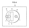
- FIGS. 3 and 4 show a structure of a substantial part of an inverted microscope 200 according to the second embodiment.
- FIG. 3 shows a structure of the inverted microscope 200 as viewed from its right side surface
- FIG. 4 shows a structure as viewed from a plane indicated by IV-IV in FIG. 3 . It should be noted that the identical part in the inverted microscope 200 to that in the inverted microscope 100 is assigned with the same symbol in the description.
- the inverted microscope 200 includes a stage 22 on which the container 1 is placed, a microscope main body 21 which supports the stage 22, the transmitting illumination device 4, the objective lens 5, a lens holding mechanism 26, and the focusing mechanism 7.
- the inverted microscope 200 further includes an observation unit 25 which enables visually observing an observation image, formed by the objective lens 5, of the sample 1a based on the transmitting illumination light transmitted from the sample 1a, and mirrors 23 and 24 which form an optical path from the objective lens 5 to the observation unit 25.
- the microscope main body 21 is a casing including the focusing mechanism 7 and the mirrors 23 and 24 therein, and an upper wall surface 21a of the microscope main body 21 is provided with an opening 21c which allows attaching the focusing mechanism 7 and the lens holding mechanism 26.
- the upper wall surface 21a is further provided with a glass window 21b which forms a sealed introduction entrance introducing an observation light from the sample 1a via the objective lens 5 into the microscope main body 21, and with a protrusion part 21e protruding upwards from the upper wall surface 21a in a cylindrical shape in the circumference of the opening 21c in the upper wall surface 21a.
- the lens holding mechanism 26 is constituted by using the revolver 6c and provided with a protrusion part 27 protruding downwards in a ring shape around the revolution axis 6x in the periphery part of the revolver 6c.
- a size of the revolver 6c in the horizontal plane is larger than the size of an image projected onto the horizontal plane of the opening 21c, that is, the opening 21c itself, and the protrusion part 27 is provided in an outer side of the opening 21c in the horizontal direction.
- the inverted microscope 200 there is a possibility that the culture fluid 1b is spilled out of the container 1 on the stage 2.
- the spilt culture fluid 1b falls down onto the lens holding mechanism 26 via a hole 22a provided on the stage 22 for securing a path of an observation light and flows down, along the lens holding mechanism 26, from its periphery.
- the inverted microscope 200 according to the embodiment is configured so that the culture fluid 1b does not fall down directly into the opening 21c, thereby preventing the intrusion of the culture fluid 1b into the opening 21c.
- the protrusion part 27 sharply protrudes downwards, there is no possibility that the culture fluid 1b flowing down along the outer side of the protrusion part 27 comes into the inner side (a side of the revolution axis 6x).
- the inverted microscope 200 is configured so that the culture fluid 1b having fallen down onto the upper wall surface 21a does not intrude into the opening 21c through the upper wall surface 21a, thereby preventing the intrusion of the culture fluid 1b into the opening 21c.
- the spilt culture fluid 1b on the upper wall surface 21a is retained on the upper wall surface 21a or discharged to the outside of the microscope main body 21 through the upper wall surface 21a.
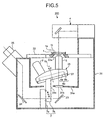
- FIG. 5 shows a structure of a substantial part of an inverted microscope 300 according to the modification.
- the inverted microscope 300 includes a microscope main body 31 instead of the microscope main body 21 based on the structure of the inverted microscope 200.
- the structure except for the microscope main body 31 in the inverted microscope 300 is the same as that in the inverted microscope 200, and the identical part is assigned with the same symbol in the description.
- the microscope main body 31 is a casing including the focusing mechanism 7 and the mirrors 23 and 24 therein, and an upper wall surface 31a of the microscope main body 31 is provided with an opening 31c which allows attaching the focusing mechanism 7 and the lens holding mechanism 26.
- the opening 31c is configured to have the same size as the opening 21c in the microscope main body 21.
- the upper wall surface 31a is further provided with a glass window 31b similarly to the glass window 21b in the microscope main body 21.
- the glass window 31b forms a sealed introduction entrance which introduces an observation light from the sample 1a via the objective lens 5 into the microscope main body 31.
- the upper wall surface 31a is configured to have an inclined plane where a front end part and a rear end part are inclined downwards from the opening 31c which is located at a level higher than the front and the rear end parts.
- the inverted microscope 300 there is a possibility that the culture fluid 1b is spilled out of the container 1 on the stage 22 by mistake.
- the spilt culture fluid 1b falls down onto the lens holding mechanism 26 via the hole 22a provided on the stage 22 and flows down, along the lens holding mechanism 26, from its periphery.
- the inverted microscope 300 according to the modification is configured so that the culture fluid 1b does not fall down directly into the opening 31c similarly to the inverted microscope 200, thereby preventing the intrusion of the culture fluid 1b into the opening 31c.
- the culture fluid 1b having fallen down onto the upper wall surface 31a is configured not to come into the opening 31c along the upper wall surface 31a.
- the culture fluid having fallen down onto the upper wall surface 31a is induced to flow down to the front end part or the rear end part along the inclined upper wall surface 31a, and retained on the upper wall surface 31a or discharged to the outside of the microscope main body 31 along the upper wall surface 31a.
- the upper wall surfaces 11a and 31a in the inverted microscopes 100 and 300 are wholly inclined surfaces respectively in the description.
- the upper wall surfaces 11a and 31a may be partially inclined at a particular location where the culture fluid 1b is often spilled.
- the upper wall surfaces 11a and 31a are configured to have the plane inclined in a front-back direction.
- the direction is not limited to the front-back direction, and the upper wall surface may be a plane inclined in a left-right direction for example.
- the direction is not limited to the front-back direction or the left-right direction, and the upper wall surface may be provided with planes inclined in more directions, for example, four planes inclined in front, back, left, and right directions.
- the protrusion part 27 is provided in a manner of protruding in the periphery part of the revolver 6c.
- the periphery on the bottom surface of the revolver 6c may be formed to have a protruding shape, for example, instead of the protrusion part 27.
Landscapes
- Physics & Mathematics (AREA)
- Chemical & Material Sciences (AREA)
- Analytical Chemistry (AREA)
- General Physics & Mathematics (AREA)
- Optics & Photonics (AREA)
- Microscoopes, Condenser (AREA)
Abstract
Description
- The present invention relates to an inverted microscope which generates an observation image of a sample by using an objective lens placed under the sample.
- Conventionally, an inverted microscope has been widely used for an observation of a sample such as a cell soaked in a culture fluid (cultured cell). In such an observation, a container such as a Petri dish filled with the culture fluid is mounted on a stage, and an objective lens provided under the sample is used to generate an observation image. In a case of performing a time-course observation of a cultured cell for example, it is necessary to replace the culture fluid. On this occasion, there is a problem that the culture fluid is spilled out of the container by mistake on the stage and the spilt fluid intrudes in a main body of the microscope, resulting in polluting an optical member and a mechanism member provided in the main body of the microscope and damaging the function thereof.
- In response to this problem, techniques disclosed in Japanese Patent Application Laid-Open No.
2002-90645 H5-50413 2006-162770 2002-90645 - In an inverted microscope disclosed in Japanese Utility Model Application Laid-Open No.
H5-50413 - In an inverted microscope disclosed in Japanese Patent Application Laid-Open No.
2006-162770 - However, in the inverted microscope described in Japanese Patent Application Laid-Open No.
2002-90645 - Further, in the inverted microscope described in Japanese Utility Model Application Laid-Open No.
H5-50413 - Further, in the inverted microscope described in Japanese Patent Application Laid-Open No.
2006-162770 - An inverted microscope according to an aspect of the present invention includes a lens holding mechanism which holds an objective lens arranged under a sample and used to form an observation image of the sample; a focusing mechanism which holds the lens holding mechanism on its upper part and moves the objective lens up and down together with the lens holding mechanism; and a microscope main body which serves as a casing including the focusing mechanism therein, and includes an opening allowing an attachment of the focusing mechanism and the lens holding mechanism in its upper wall surface. A size of the lens holding mechanism in a horizontal plane is larger than a size of an image projected onto the horizontal plane of the opening.
- The above and other objects, features, advantages and technical and industrial significance of this invention will be better understood by reading the following detailed description of presently preferred embodiments of the invention, when considered in connection with the accompanying drawings.
-
-
FIG. 1 is a view showing a structure of an inverted microscope according to a first embodiment of the present invention; -
FIG. 2 is a view showing a structure as viewed from a plane shown by II-II inFIG. 1 ; -
FIG. 3 is a view showing a structure of an inverted microscope according to a second embodiment of the present invention; -
FIG. 4 is a view showing a structure as viewed from a plane shown by IV-IV inFIG. 3 ; and -
FIG. 5 is a view showing a structure of an inverted microscope according to a modification of the second embodiment. - Exemplary embodiments of an inverted microscope according to the present invention will be explained in detail below with reference to the accompanying drawings. It should be noted that the present invention is not limited by the embodiments, and that the identical part is assigned with the same symbol in the description throughout the drawings.
- First, an inverted microscope according to a first embodiment of the present invention will be explained.
FIGS. 1 and2 show a structure of a substantial part of an invertedmicroscope 100 according to the first embodiment.FIG. 1 shows a structure of the invertedmicroscope 100 as viewed from a right side surface andFIG. 2 shows a structure as viewed from a plane shown by II-II inFIG. 1 . - As shown in
FIGS. 1 and2 , the invertedmicroscope 100 includes astage 2, a supportingmechanism 3, a transmittingillumination device 4, anobjective lens 5, alens holding mechanism 6, and afocusing mechanism 7. Acontainer 1 which contains asample 1a as an observation target and aculture fluid 1b is placed on thestage 2. The supportingmechanism 3 supports thestage 2 so that thestage 2 can move in a horizontal plane (in a plane including a lateral direction and a direction perpendicular to the drawn surface inFIG. 1 ). The transmittingillumination device 4 transmits an illumination from above of thesample 1a. Theobjective lens 5 is arranged under thesample 1a. Thelens holding mechanism 6 holds theobjective lens 5. Thefocusing mechanism 7 holds thelens holding mechanism 6 on its upper part. - The inverted
microscope 100 further includes an incident-light illumination device 8 which irradiates thesample 1a via theobjective lens 5 with an excited light, awavelength selector 9 which makes optical paths respectively for the excited light exposed to thesample 1a and a fluorescence emitted from thesample 1a collectively branch off, animaging device 10 which captures an observation image, formed by theobjective lens 5, of thesample 1a based on the fluorescence emitted from thesample 1a or the transmitting illumination light transmitted from thesample 1a, and a microscopemain body 11 which serves as a casing including therein the supportingmechanism 3, thefocusing mechanism 7, the incident-light illumination device 8, thewavelength selector 9, and theimaging device 10. - The inverted
microscope 100 still further includes acover 13 which is attached at a front face part (left side surface part inFIG. 1 ) of the microscopemain body 11 with ahinge 12. By using thehinge 12, thecover 13 can be freely opened and closed with respect to the microscopemain body 11, and covers thecontainer 1, thestage 2, the transmittingillumination device 4, theobjective lens 5, and thelens holding mechanism 6 to block a light from the outside when closed. In other words, the microscopemain body 11 and thecover 13 form a dark box when thecover 13 is closed. Thecover 13 when closed overlaps a peripheral edge portion of the microscopemain body 11, thereby enhancing the function as a dark box. - The
lens holding mechanism 6 includes arevolver 6c constituted by using afixation part 6a fixed on the upper part of thefocusing mechanism 7 and amovable part 6b fitted to cover thefixation part 6a. Themovable part 6b holds theobjective lens 5 so that theobjective lens 5 can freely revolve around arevolution axis 6x as a center axis of thefixation part 6a having a cylindrical column shape. Themovable part 6b also holds anotherobjective lens 5' whose magnification and the like are different from theobjective lens 5, and selectively arranges one of theobjective lenses sample 1a. Therevolution axis 6x is inclined by an inclination angle θ with respect to an optical axis OA for observing thesample 1a, that is, an optical axis of theobjective lens sample 1a, and thereby a bottom surface part of therevolver 6c is inclined by the inclination angle θ from the horizontal plane. The inclination angle θ is expected to be 5° to 30° and more preferably 15°, for example. - The
lens holding mechanism 6 integrally includes aprotruding edge part 6d and aprotective wall part 14, theprotruding edge part 6d having an orbicular zone shape and being provided in a manner of protruding from the periphery of themovable part 6b which revolves around therevolution axis 6x, and theprotective wall part 14 having a cylindrical shape and being joined to the periphery of the protrudingedge part 6d. With therevolver 6c and the protrudingedge part 6d, thelens holding mechanism 6 has a larger size in its horizontal plane than an image projected onto a horizontal plane of an opening formed in the microscopemain body 11. A magnitude correlation between the opening in the microscopemain body 11 and thelens holding mechanism 6 will be separately explained in detail. - The focusing
mechanism 7 is constituted by using afixation part 7a which is provided in a manner of standing on a bottom part of the microscopemain body 11 and amovable part 7b which moves up and down along thefixation part 7a, and thefixation part 6a of therevolver 6c is fixed to an upper end part of themovable part 7b. The focusingmechanism 7, to which an interlocking operation mechanism though not shown is connected, makes themovable part 7b move up and down according to an operation of the interlocking operation mechanism, and makes thelens holding mechanism 6 and theobjective lenses objective lens 5 is arranged under thesample 1a, theobjective lens 5 is focused on thesample 1a through the up/down movement operated by the focusingmechanism 7. - The microscope
main body 11 is constituted by using anupper wall surface 11a and anupright wall surface 11b in the front face part of the casing structure. Theupper wall surface 11a is provided with an opening 11c which allows an attachment of the focusingmechanism 7 and thelens holding mechanism 6, and theupright wall surface 11b is provided with anopening 11d which allows a horizontal protrusion of thestage 2 from the supportingmechanism 3. Aprotrusion part 11e which protrudes upwards from theupper wall surface 11a in a cylindrical shape is provided in a circumferential part of the opening 11c of theupper wall surface 11a, and areservoir part 11f is provided at a front end part (left end part inFIGS. 1 and2 ) of theupper wall surface 11a. - The
upper wall surface 11a is configured to have an inclined plane where the front end part is inclined downwards from a rear end part as a joint part with theupright wall surface 11b as a whole. Theupper wall surface 11a as the inclined plane is configured to be perpendicular to therevolution axis 6x of therevolver 6c, parallel to the bottom surface of therevolver 6c, and inclined by the inclination angle θ with respect to the horizontal plane. Here, "being perpendicular to therevolution axis 6x" does not necessarily mean being exactly perpendicular and can be a state of being substantially perpendicular. - The opening 11c is configured to have, along the
upper wall surface 11a, a circle shape whose size is larger than that of a contour of therevolver 6c by a predetermined degree. Specifically, the size is configured so that therevolver 6c and theprotrusion part 11e do not have direct contact with each other when therevolver 6c is moved up and down by the focusingmechanism 7. - In contrast, the size of the
lens holding mechanism 6 which is determined by therevolver 6c and the protrudingedge part 6d is configured to be larger than that of the opening 11c along theupper wall surface 11a, and larger in the horizontal plane than the size of an image projected onto the horizontal plane of the opening 11c. This magnitude correlation is always satisfied within a range of the up/down movement when thelens holding mechanism 6 is moved up and down by the focusingmechanism 7. - In such an
inverted microscope 100, there is a possibility that theculture fluid 1b is spilled out of thecontainer 1 on thestage 2 by mistake. In this case, the spiltculture fluid 1b falls down onto thelens holding mechanism 6 via ahole 2a provided on thestage 2 for securing a path of an observation light and flows down, along thelens holding mechanism 6, from its periphery, that is, theprotective wall 14. Here, theinverted microscope 100 according to the embodiment is configured so that theculture fluid 1b does not fall down directly into the opening 11c, thereby preventing an intrusion of theculture fluid 1b into the opening 11c. At the same time, theculture fluid 1b falling down from the periphery of thestage 2 is prevented from falling down directly into the opening 11c. Sine theprotective wall part 14 sharply protrudes downwards, there is no possibility that theculture fluid 1b flowing down along the outer side of theprotective wall part 14 comes into the inner side thereof. - The
protrusion part 11e provided in the circumferential part of the opening 11c protrudes in a direction substantially perpendicular to theupper wall surface 11a, that is, substantially parallel to therevolution axis 6x. On the other hand, theprotective wall part 14 is provided substantially parallel to and all around the circumference of theprotrusion part 11e, surrounding theprotrusion part 11e. Theprotrusion part 11e and theprotective wall part 14 are configured to overlap in a direction along theupper wall surface 11a at least at a part within the range of the up/down movement of thelens holding mechanism 6 operated by the focusingmechanism 7. - In such an
inverted microscope 100, there is a possibility that theculture fluid 1b is spilled out of thecontainer 1 on thestage 2 by mistake. In this case, the spiltculture fluid 1b falls down onto thelens holding mechanism 6 via thehole 2a provided on thestage 2, and splashes through thelens holding mechanism 6, theupright wall surface 11b, and the like. Here, theinverted microscope 100 according to the embodiment is configured so that theculture fluid 1b which has fallen down and splashed around does not intrude directly into the opening 11c from a direction along theupper wall surface 11a, thereby preventing the intrusion of theculture fluid 1b into the opening 11c. At the same time, theculture fluid 1b which has fallen down from the periphery of thestage 2 and splashed around is also prevented from intruding directly into the opening 11c from the direction along theupper wall surface 11a. - Specifically, when the inclination angle θ of the
revolution axis 6x is 15° and the range of the up/down movement of thelens holding mechanism 6 operated by the focusingmechanism 7 is 10 mm for example, a height of each of theprotrusion part 11e and theprotective wall part 14 in the direction of therevolution axis 6x is set to 9.7 mm. This setting allows at least a part of theprotrusion part 11e and theprotective wall part 14 to always overlap in the direction along theupper wall surface 11a within the range of the up/down movement of thelens holding mechanism 6. Besides, by setting a distance between theprotrusion part 11e and a side surface as the periphery of therevolver 6c in the direction along theupper wall surface 11a to 2.6 mm or more in this case, a contact between therevolver 6c and theprotrusion part 11e within the range of the up/down movement of thelens holding mechanism 6 can always be prevented. - By having the
protrusion part 11e in the circumference of the opening 11c, theinverted microscope 100 is configured so that the culture fluid having fallen down onto theupper wall surface 11a does not intrude into the opening 11c through theupper wall surface 11a, thereby preventing the intrusion of theculture fluid 1b into the opening 11c. The spiltculture fluid 1b on theupper wall surface 11a is induced to flow down toward a front end part along the inclinedupper wall surface 11a, flow into, and be accumulated in thereservoir part 11f. An operator of theinverted microscope 100 can easily deal with the accumulatedculture fluid 1b by wiping or blotting. Theinverted microscope 100 can be provided with a discharge path instead of thereservoir part 11f to discharge theculture fluid 1b flowing into the discharge path through theupper wall surface 11a out of the microscopemain body 11. - At the same time, the
stage 2 is provided with aconvex wall part 2b surrounding between thecontainer 1 and theopening 11d along the vertical plane. Thus, theinverted microscope 100 is configured not to allow the intrusion of, for example, theculture fluid 1b spilled onto thestage 2 out of thecontainer 1 into theopening 11d via thestage 2, thereby preventing the intrusion of theculture fluid 1b into theopening 11d. - As described above, it is possible to surely realize a waterproof condition within the microscope
main body 11 without allowing the intrusion of fluid such as theculture fluid 1b spilled out of thecontainer 1 on thestage 2 into the microscopemain body 11 through theopenings 11c and 11d in theinverted microscope 100 according to the first embodiment. Hence, it is possible to prevent the pollution, caused by fluid, of the optical member and the mechanism member provided within the microscopemain body 11. Further, thesample 1a and the like dropped by mistake from thestage 2 can be held on theupper wall surface 11a and easily gotten rid of without allowing the intrusion into the microscopemain body 11 in theinverted microscope 100. - Next, an inverted microscope according to a second embodiment of the present invention will be explained.
FIGS. 3 and4 show a structure of a substantial part of aninverted microscope 200 according to the second embodiment.FIG. 3 shows a structure of theinverted microscope 200 as viewed from its right side surface, andFIG. 4 shows a structure as viewed from a plane indicated by IV-IV inFIG. 3 . It should be noted that the identical part in theinverted microscope 200 to that in theinverted microscope 100 is assigned with the same symbol in the description. - As shown in
FIGS. 3 and4 , theinverted microscope 200 includes astage 22 on which thecontainer 1 is placed, a microscopemain body 21 which supports thestage 22, the transmittingillumination device 4, theobjective lens 5, alens holding mechanism 26, and the focusingmechanism 7. Theinverted microscope 200 further includes anobservation unit 25 which enables visually observing an observation image, formed by theobjective lens 5, of thesample 1a based on the transmitting illumination light transmitted from thesample 1a, and mirrors 23 and 24 which form an optical path from theobjective lens 5 to theobservation unit 25. - The microscope
main body 21 is a casing including the focusingmechanism 7 and themirrors upper wall surface 21a of the microscopemain body 21 is provided with anopening 21c which allows attaching the focusingmechanism 7 and thelens holding mechanism 26. Theupper wall surface 21a is further provided with aglass window 21b which forms a sealed introduction entrance introducing an observation light from thesample 1a via theobjective lens 5 into the microscopemain body 21, and with aprotrusion part 21e protruding upwards from theupper wall surface 21a in a cylindrical shape in the circumference of theopening 21c in theupper wall surface 21a. - The
lens holding mechanism 26 is constituted by using therevolver 6c and provided with aprotrusion part 27 protruding downwards in a ring shape around therevolution axis 6x in the periphery part of therevolver 6c. A size of therevolver 6c in the horizontal plane (in the plane including the lateral direction and the direction perpendicular to the drawn surface inFIG. 3 ) is larger than the size of an image projected onto the horizontal plane of theopening 21c, that is, theopening 21c itself, and theprotrusion part 27 is provided in an outer side of theopening 21c in the horizontal direction. - In such an
inverted microscope 200, there is a possibility that theculture fluid 1b is spilled out of thecontainer 1 on thestage 2. In this case, the spiltculture fluid 1b falls down onto thelens holding mechanism 26 via ahole 22a provided on thestage 22 for securing a path of an observation light and flows down, along thelens holding mechanism 26, from its periphery. Here, theinverted microscope 200 according to the embodiment is configured so that theculture fluid 1b does not fall down directly into theopening 21c, thereby preventing the intrusion of theculture fluid 1b into theopening 21c. Sine theprotrusion part 27 sharply protrudes downwards, there is no possibility that theculture fluid 1b flowing down along the outer side of theprotrusion part 27 comes into the inner side (a side of therevolution axis 6x). - By having the
protrusion part 21e in the circumference of theopening 21c, theinverted microscope 200 is configured so that theculture fluid 1b having fallen down onto theupper wall surface 21a does not intrude into theopening 21c through theupper wall surface 21a, thereby preventing the intrusion of theculture fluid 1b into theopening 21c. The spiltculture fluid 1b on theupper wall surface 21a is retained on theupper wall surface 21a or discharged to the outside of the microscopemain body 21 through theupper wall surface 21a. - As described above, it is possible to surely realize a waterproof condition within the microscope
main body 21 without allowing the intrusion of fluid such as theculture fluid 1b spilled out of thecontainer 1 on thestage 22 into the microscopemain body 21 through theopening 21c in theinverted microscope 200 according to the second embodiment. Hence, it is possible to prevent the pollution, caused by fluid, of the optical member and the mechanism member provided within the microscopemain body 21. - Next, a modification of the inverted microscope according to the second embodiment will be explained.
FIG. 5 shows a structure of a substantial part of aninverted microscope 300 according to the modification. As shown inFIG. 5 , theinverted microscope 300 includes a microscopemain body 31 instead of the microscopemain body 21 based on the structure of theinverted microscope 200. The structure except for the microscopemain body 31 in theinverted microscope 300 is the same as that in theinverted microscope 200, and the identical part is assigned with the same symbol in the description. - The microscope
main body 31 is a casing including the focusingmechanism 7 and themirrors upper wall surface 31a of the microscopemain body 31 is provided with anopening 31c which allows attaching the focusingmechanism 7 and thelens holding mechanism 26. Theopening 31c is configured to have the same size as theopening 21c in the microscopemain body 21. Theupper wall surface 31a is further provided with aglass window 31b similarly to theglass window 21b in the microscopemain body 21. Theglass window 31b forms a sealed introduction entrance which introduces an observation light from thesample 1a via theobjective lens 5 into the microscopemain body 31. Besides, theupper wall surface 31a is configured to have an inclined plane where a front end part and a rear end part are inclined downwards from theopening 31c which is located at a level higher than the front and the rear end parts. - In such an
inverted microscope 300, there is a possibility that theculture fluid 1b is spilled out of thecontainer 1 on thestage 22 by mistake. In this case, the spiltculture fluid 1b falls down onto thelens holding mechanism 26 via thehole 22a provided on thestage 22 and flows down, along thelens holding mechanism 26, from its periphery. Here, theinverted microscope 300 according to the modification is configured so that theculture fluid 1b does not fall down directly into theopening 31c similarly to theinverted microscope 200, thereby preventing the intrusion of theculture fluid 1b into theopening 31c. - Furthermore, since the
upper wall surface 31a in theinverted microscope 300 has the inclined plane where theopening 31c is positioned at the highest level, theculture fluid 1b having fallen down onto theupper wall surface 31a is configured not to come into theopening 31c along theupper wall surface 31a. Thus, the intrusion of theculture fluid 1b into theopening 31c is prevented. The culture fluid having fallen down onto theupper wall surface 31a is induced to flow down to the front end part or the rear end part along the inclinedupper wall surface 31a, and retained on theupper wall surface 31a or discharged to the outside of the microscopemain body 31 along theupper wall surface 31a. - As described above, it is possible to surely realize a waterproof condition within the microscope
main body 31 without allowing the intrusion of fluid such as theculture fluid 1b spilled out of thecontainer 1 on thestage 22 into the microscopemain body 31 through theopening 31c in theinverted microscope 300 according to the modification. Hence, it is possible to prevent the pollution, caused by fluid, of the optical member and the mechanism member provided within the microscopemain body 31. - Exemplary embodiments of the present invention are explained as the first and the second embodiments above. However, the present invention is not limited to the first and the second embodiments and various modifications may be made without departing from the spirit or scope of the present invention.
- For example, the upper wall surfaces 11a and 31a in the
inverted microscopes culture fluid 1b is often spilled. Besides, the upper wall surfaces 11a and 31a are configured to have the plane inclined in a front-back direction. However, the direction is not limited to the front-back direction, and the upper wall surface may be a plane inclined in a left-right direction for example. Furthermore, the direction is not limited to the front-back direction or the left-right direction, and the upper wall surface may be provided with planes inclined in more directions, for example, four planes inclined in front, back, left, and right directions. - In the
inverted microscopes protrusion part 27 is provided in a manner of protruding in the periphery part of therevolver 6c. However, the periphery on the bottom surface of therevolver 6c may be formed to have a protruding shape, for example, instead of theprotrusion part 27. - Additional advantages and modifications will readily occur to those skilled in the art. Therefore, the invention in its broader aspects is not limited to the specific details and representative embodiments shown and described herein. Accordingly, various modifications may be made without departing from the spirit or scope of the general inventive concept as defined by the appended claims and their equivalents.
Claims (10)
- An inverted microscope (100; 200; 300) comprising:a lens holding mechanism (6; 26) which holds an objective lens (5, 5') arranged under a sample (1a) and used to form an observation image of the sample (1a) ;a focusing mechanism which (7) holds the lens holding mechanism (26) on its upper part and moves the objective lens (5, 5') up and down together with the lens holding mechanism (26); anda microscope main body (11; 21; 31) which serves as a casing including the focusing mechanism (7) therein, and includes an opening (11c; 21c; 31c) allowing an attachment of the focusing mechanism (7) and the lens holding mechanism (26) in its upper wall surface (11a; 21a; 31a), whereina size of the lens holding mechanism (6; 26) in a horizontal plane is larger than a size of an image projected onto the horizontal plane of the opening (11c; 21c; 31c).
- The inverted microscope (100) according to claim 1, further comprising a blockage member (14) which is provided integrally with the lens holding mechanism (6) and blocks an intrusion of fluid spilled onto the lens holding mechanism (6) into the opening (11c).
- The inverted microscope (100; 200; 300) according to claim 1 or 2, wherein the lens holding mechanism (6; 26) includes a revolver part (6c) which holds the objective lens (5, 5') so that the objective lens (5, 5') can revolve around a predetermined axis (6x), and a protruding edge part which is provided in a manner of protruding in a periphery of the revolver part (6c) around the predetermined axis (6x).
- The inverted microscope (100; 300) according to any one of claims 1 to 3, wherein the upper wall surface (11a; 31a) has an inclined plane which enables fluid spilled onto the upper wall surface (11a; 31a) to flow down toward a predetermined location except for the opening (11c; 31c).
- The inverted microscope (100; 200) according to any one of claims 1 to 4, wherein the microscope main body (11; 21) includes a protrusion part (11e; 21e) protruding upwards from the upper wall surface (11a; 21a) in a circumference of the opening (11c; 21c).
- The inverted microscope (100; 200) according to any on e of claims 1 to 4, wherein
the lens holding mechanism (6; 26) includes a revolver part (6c) which holds the objective lens (5, 5') so that the objective lens (5, 5') can revolve around a predetermined axis (6x),
the upper wall surface (11a; 21a) has an inclined plane which is substantially perpendicular to the predetermined axis (6x) around the opening (11c; 21c), and
the microscope main body (11; 21) includes a protrusion part (11e; 21e) protruding upwards from the upper wall surface (11a; 21a) in a circumference of the opening (11c; 21c). - The inverted microscope (100; 200) according to claim 5 or 6, further comprising a surrounding part (14) which is provided integrally with the lens holding mechanism (6; 26) and surrounds the protrusion part (11e; 21e).
- The inverted microscope (100; 200; 300) according to claim 4 or 6, wherein the microscope main body (11; 21; 31) includes at least one of a reservoir part (6c) and a discharge path, the reservoir part (6c) accumulating fluid which is spilled onto the upper wall surface (11a; 21a; 31a) and induced to flow down via the inclined plane, and the discharge path discharging the fluid.
- The inverted microscope (100) according to claim 2, wherein
the lens holding mechanism (6) includes a revolver part (6c) which holds the objective lens (5, 5') so that the objective lens (5, 5') can revolve around a predetermined axis (6x), and
the blockage member (14) is provided in a periphery part of the revolver part (6c) around the predetermined axis (6x). - The inverted microscope (100) according to any one of claims 1 to 9, further comprising:a stage (2) on which the sample (1a) is placed;a stage supporting mechanism (3) which is provided in the microscope main body (11), supports the stage (2), and makes the stage (2) horizontally protrude from an opening (11d) which is dedicated to the stage (2) and formed in the microscope main body (11); anda stage blockage member (2b) which is provided on the stage (2) and blocks an intrusion of fluid spilled onto the stage 82) into the opening (11d) dedicated to the stage (2).
Applications Claiming Priority (1)
| Application Number | Priority Date | Filing Date | Title |
|---|---|---|---|
| JP2007154266A JP5173270B2 (en) | 2007-06-11 | 2007-06-11 | Inverted microscope |
Publications (3)
| Publication Number | Publication Date |
|---|---|
| EP2003481A2 true EP2003481A2 (en) | 2008-12-17 |
| EP2003481A3 EP2003481A3 (en) | 2010-01-13 |
| EP2003481B1 EP2003481B1 (en) | 2017-03-01 |
Family
ID=39800505
Family Applications (1)
| Application Number | Title | Priority Date | Filing Date |
|---|---|---|---|
| EP08010040.7A Ceased EP2003481B1 (en) | 2007-06-11 | 2008-06-02 | Inverted microscope |
Country Status (3)
| Country | Link |
|---|---|
| US (1) | US8027084B2 (en) |
| EP (1) | EP2003481B1 (en) |
| JP (1) | JP5173270B2 (en) |
Cited By (2)
| Publication number | Priority date | Publication date | Assignee | Title |
|---|---|---|---|---|
| DE102020111717A1 (en) | 2020-04-29 | 2021-11-04 | Carl Zeiss Microscopy Gmbh | PROTECTIVE DEVICE AND METHOD FOR PROTECTING MICROSCOPE COMPONENTS FROM CONTACT WITH LIQUID |
| EP4198603A1 (en) * | 2021-12-16 | 2023-06-21 | Cytena Gmbh | Microscope |
Families Citing this family (7)
| Publication number | Priority date | Publication date | Assignee | Title |
|---|---|---|---|---|
| DE102007018862A1 (en) * | 2007-04-18 | 2008-10-23 | Carl Zeiss Microimaging Gmbh | Objective change device for microscopes |
| JP4409586B2 (en) * | 2007-06-20 | 2010-02-03 | オリンパス株式会社 | Box-type electric microscope |
| EP2312367A1 (en) * | 2009-10-16 | 2011-04-20 | Olympus Corporation | Laser scanning microscope |
| US20120050853A1 (en) * | 2010-04-09 | 2012-03-01 | Andrew Ross Miller | Portable fluorescence microscope |
| JP5586326B2 (en) * | 2010-05-28 | 2014-09-10 | オリンパス株式会社 | Inverted microscope |
| DE102014110485B4 (en) * | 2014-07-24 | 2017-05-11 | Leica Microsystems Cms Gmbh | Microscope with covers for combined anti-pinch protection and light protection |
| GB201508376D0 (en) * | 2015-05-15 | 2015-07-01 | Univ St Andrews | Light sheet imaging |
Citations (3)
| Publication number | Priority date | Publication date | Assignee | Title |
|---|---|---|---|---|
| JPH0550413U (en) | 1991-12-09 | 1993-07-02 | 株式会社ニコン | Inverted microscope |
| JP2002090645A (en) | 2000-09-14 | 2002-03-27 | Olympus Optical Co Ltd | microscope |
| JP2006162770A (en) | 2004-12-03 | 2006-06-22 | Keyence Corp | Microscope |
Family Cites Families (4)
| Publication number | Priority date | Publication date | Assignee | Title |
|---|---|---|---|---|
| JPS6056017U (en) * | 1983-09-26 | 1985-04-19 | オリンパス光学工業株式会社 | inverted microscope |
| JP4094108B2 (en) * | 1998-03-23 | 2008-06-04 | オリンパス株式会社 | Inverted microscope device |
| DE10050825A1 (en) * | 2000-10-06 | 2002-04-18 | Zeiss Carl Jena Gmbh | Protection against moisture ingress for an inverted microscope |
| JP4668609B2 (en) * | 2004-12-28 | 2011-04-13 | オリンパス株式会社 | Culture observation equipment |
-
2007
- 2007-06-11 JP JP2007154266A patent/JP5173270B2/en not_active Expired - Fee Related
-
2008
- 2008-06-02 EP EP08010040.7A patent/EP2003481B1/en not_active Ceased
- 2008-06-09 US US12/135,347 patent/US8027084B2/en not_active Expired - Fee Related
Patent Citations (3)
| Publication number | Priority date | Publication date | Assignee | Title |
|---|---|---|---|---|
| JPH0550413U (en) | 1991-12-09 | 1993-07-02 | 株式会社ニコン | Inverted microscope |
| JP2002090645A (en) | 2000-09-14 | 2002-03-27 | Olympus Optical Co Ltd | microscope |
| JP2006162770A (en) | 2004-12-03 | 2006-06-22 | Keyence Corp | Microscope |
Cited By (4)
| Publication number | Priority date | Publication date | Assignee | Title |
|---|---|---|---|---|
| DE102020111717A1 (en) | 2020-04-29 | 2021-11-04 | Carl Zeiss Microscopy Gmbh | PROTECTIVE DEVICE AND METHOD FOR PROTECTING MICROSCOPE COMPONENTS FROM CONTACT WITH LIQUID |
| US11221474B2 (en) | 2020-04-29 | 2022-01-11 | Carl Zeiss Microscopy Gmbh | Protective device and method for protecting microscope components from contact with a liquid |
| EP4198603A1 (en) * | 2021-12-16 | 2023-06-21 | Cytena Gmbh | Microscope |
| US12105273B2 (en) | 2021-12-16 | 2024-10-01 | Cytena Gmbh | Microscope having movable multi-objective optics module |
Also Published As
| Publication number | Publication date |
|---|---|
| JP2008304859A (en) | 2008-12-18 |
| EP2003481A3 (en) | 2010-01-13 |
| EP2003481B1 (en) | 2017-03-01 |
| US20080304145A1 (en) | 2008-12-11 |
| JP5173270B2 (en) | 2013-04-03 |
| US8027084B2 (en) | 2011-09-27 |
Similar Documents
| Publication | Publication Date | Title |
|---|---|---|
| EP2003481B1 (en) | Inverted microscope | |
| US8213081B2 (en) | Objective replacement device for microscopes | |
| EP2196836B1 (en) | Automatic focusing device and microscope | |
| EP1703311A1 (en) | Immersion objective lens, fluorometric analyzer, and inverted microscope | |
| US20080170292A1 (en) | Observation apparatus provided with immersion objective lens | |
| EP3279713A1 (en) | Observation apparatus | |
| JP5228257B2 (en) | Visible centrifuge and observation device | |
| US20070291360A1 (en) | Device and Method for Examining Chemical and/or Biological Samples, and Objective Cap | |
| JP5594405B2 (en) | Centrifuge microscope | |
| US20100177381A1 (en) | Sample Holding System for a Microscope | |
| JP2008276070A (en) | Magnifying image pickup apparatus | |
| CN105319695B (en) | Transmitted light microscope and method for transmitted light microscopy | |
| EP2579086B1 (en) | Inverted microscope | |
| CN109643012B (en) | Observation device | |
| EP1717630B1 (en) | Microscope apparatus with immersion liquid feeding mechanism | |
| US6268959B1 (en) | Inverted microscope with objective lens view opening and method for using same | |
| JP7301816B2 (en) | Optical lenses, media feeders, and microscopes for use in media feeders and lenses | |
| JP2012147739A (en) | Observation device | |
| US7035002B2 (en) | Reflector turret for an inverted microscope | |
| JP2002344786A (en) | Imaging device | |
| JP4643182B2 (en) | Total reflection microscope | |
| JP2001507140A (en) | Microscope condenser with receiver | |
| JP2565513Y2 (en) | Inverted microscope | |
| JP6953678B2 (en) | Formed component analyzer and formed component analysis method | |
| JP2004317957A (en) | Petri dish for microscope observation and its lid member |
Legal Events
| Date | Code | Title | Description |
|---|---|---|---|
| PUAI | Public reference made under article 153(3) epc to a published international application that has entered the european phase |
Free format text: ORIGINAL CODE: 0009012 |
|
| AK | Designated contracting states |
Kind code of ref document: A2 Designated state(s): AT BE BG CH CY CZ DE DK EE ES FI FR GB GR HR HU IE IS IT LI LT LU LV MC MT NL NO PL PT RO SE SI SK TR |
|
| AX | Request for extension of the european patent |
Extension state: AL BA MK RS |
|
| PUAL | Search report despatched |
Free format text: ORIGINAL CODE: 0009013 |
|
| AK | Designated contracting states |
Kind code of ref document: A3 Designated state(s): AT BE BG CH CY CZ DE DK EE ES FI FR GB GR HR HU IE IS IT LI LT LU LV MC MT NL NO PL PT RO SE SI SK TR |
|
| AX | Request for extension of the european patent |
Extension state: AL BA MK RS |
|
| 17P | Request for examination filed |
Effective date: 20100707 |
|
| AKX | Designation fees paid |
Designated state(s): DE |
|
| RAP1 | Party data changed (applicant data changed or rights of an application transferred) |
Owner name: OLYMPUS CORPORATION |
|
| GRAJ | Information related to disapproval of communication of intention to grant by the applicant or resumption of examination proceedings by the epo deleted |
Free format text: ORIGINAL CODE: EPIDOSDIGR1 |
|
| GRAP | Despatch of communication of intention to grant a patent |
Free format text: ORIGINAL CODE: EPIDOSNIGR1 |
|
| RAP1 | Party data changed (applicant data changed or rights of an application transferred) |
Owner name: OLYMPUS CORPORATION |
|
| RAP1 | Party data changed (applicant data changed or rights of an application transferred) |
Owner name: OLYMPUS CORPORATION |
|
| INTG | Intention to grant announced |
Effective date: 20160928 |
|
| RIN1 | Information on inventor provided before grant (corrected) |
Inventor name: HASEGAWA, KAZUHIRO |
|
| RIN1 | Information on inventor provided before grant (corrected) |
Inventor name: HASEGAWA, KAZUHIRO |
|
| GRAS | Grant fee paid |
Free format text: ORIGINAL CODE: EPIDOSNIGR3 |
|
| GRAA | (expected) grant |
Free format text: ORIGINAL CODE: 0009210 |
|
| AK | Designated contracting states |
Kind code of ref document: B1 Designated state(s): DE |
|
| RIN1 | Information on inventor provided before grant (corrected) |
Inventor name: HASEGAWA, KAZUHIRO |
|
| REG | Reference to a national code |
Ref country code: DE Ref legal event code: R096 Ref document number: 602008048899 Country of ref document: DE |
|
| REG | Reference to a national code |
Ref country code: DE Ref legal event code: R097 Ref document number: 602008048899 Country of ref document: DE |
|
| PLBE | No opposition filed within time limit |
Free format text: ORIGINAL CODE: 0009261 |
|
| STAA | Information on the status of an ep patent application or granted ep patent |
Free format text: STATUS: NO OPPOSITION FILED WITHIN TIME LIMIT |
|
| 26N | No opposition filed |
Effective date: 20171204 |
|
| PGFP | Annual fee paid to national office [announced via postgrant information from national office to epo] |
Ref country code: DE Payment date: 20190619 Year of fee payment: 12 |
|
| REG | Reference to a national code |
Ref country code: DE Ref legal event code: R119 Ref document number: 602008048899 Country of ref document: DE |
|
| PG25 | Lapsed in a contracting state [announced via postgrant information from national office to epo] |
Ref country code: DE Free format text: LAPSE BECAUSE OF NON-PAYMENT OF DUE FEES Effective date: 20210101 |