EP2003351A1 - Double-row rolling bearing for supporting pinion shaft, and rolling bearing device with the same - Google Patents
Double-row rolling bearing for supporting pinion shaft, and rolling bearing device with the same Download PDFInfo
- Publication number
- EP2003351A1 EP2003351A1 EP07740854A EP07740854A EP2003351A1 EP 2003351 A1 EP2003351 A1 EP 2003351A1 EP 07740854 A EP07740854 A EP 07740854A EP 07740854 A EP07740854 A EP 07740854A EP 2003351 A1 EP2003351 A1 EP 2003351A1
- Authority
- EP
- European Patent Office
- Prior art keywords
- pinion
- diameter
- larger
- gear
- outer ring
- Prior art date
- Legal status (The legal status is an assumption and is not a legal conclusion. Google has not performed a legal analysis and makes no representation as to the accuracy of the status listed.)
- Withdrawn
Links
- 238000005096 rolling process Methods 0.000 title claims abstract description 136
- 230000002093 peripheral effect Effects 0.000 claims abstract description 60
- 238000000034 method Methods 0.000 claims description 13
- 238000010276 construction Methods 0.000 description 6
- 230000036316 preload Effects 0.000 description 5
- 125000006850 spacer group Chemical group 0.000 description 2
- 230000002411 adverse Effects 0.000 description 1
- 230000000694 effects Effects 0.000 description 1
- 230000002028 premature Effects 0.000 description 1
Images






Classifications
-
- F—MECHANICAL ENGINEERING; LIGHTING; HEATING; WEAPONS; BLASTING
- F16—ENGINEERING ELEMENTS AND UNITS; GENERAL MEASURES FOR PRODUCING AND MAINTAINING EFFECTIVE FUNCTIONING OF MACHINES OR INSTALLATIONS; THERMAL INSULATION IN GENERAL
- F16C—SHAFTS; FLEXIBLE SHAFTS; ELEMENTS OR CRANKSHAFT MECHANISMS; ROTARY BODIES OTHER THAN GEARING ELEMENTS; BEARINGS
- F16C19/00—Bearings with rolling contact, for exclusively rotary movement
- F16C19/02—Bearings with rolling contact, for exclusively rotary movement with bearing balls essentially of the same size in one or more circular rows
- F16C19/14—Bearings with rolling contact, for exclusively rotary movement with bearing balls essentially of the same size in one or more circular rows for both radial and axial load
- F16C19/18—Bearings with rolling contact, for exclusively rotary movement with bearing balls essentially of the same size in one or more circular rows for both radial and axial load with two or more rows of balls
- F16C19/181—Bearings with rolling contact, for exclusively rotary movement with bearing balls essentially of the same size in one or more circular rows for both radial and axial load with two or more rows of balls with angular contact
- F16C19/182—Bearings with rolling contact, for exclusively rotary movement with bearing balls essentially of the same size in one or more circular rows for both radial and axial load with two or more rows of balls with angular contact in tandem arrangement
-
- F—MECHANICAL ENGINEERING; LIGHTING; HEATING; WEAPONS; BLASTING
- F16—ENGINEERING ELEMENTS AND UNITS; GENERAL MEASURES FOR PRODUCING AND MAINTAINING EFFECTIVE FUNCTIONING OF MACHINES OR INSTALLATIONS; THERMAL INSULATION IN GENERAL
- F16C—SHAFTS; FLEXIBLE SHAFTS; ELEMENTS OR CRANKSHAFT MECHANISMS; ROTARY BODIES OTHER THAN GEARING ELEMENTS; BEARINGS
- F16C19/00—Bearings with rolling contact, for exclusively rotary movement
- F16C19/54—Systems consisting of a plurality of bearings with rolling friction
- F16C19/546—Systems with spaced apart rolling bearings including at least one angular contact bearing
- F16C19/547—Systems with spaced apart rolling bearings including at least one angular contact bearing with two angular contact rolling bearings
- F16C19/548—Systems with spaced apart rolling bearings including at least one angular contact bearing with two angular contact rolling bearings in O-arrangement
-
- F—MECHANICAL ENGINEERING; LIGHTING; HEATING; WEAPONS; BLASTING
- F16—ENGINEERING ELEMENTS AND UNITS; GENERAL MEASURES FOR PRODUCING AND MAINTAINING EFFECTIVE FUNCTIONING OF MACHINES OR INSTALLATIONS; THERMAL INSULATION IN GENERAL
- F16C—SHAFTS; FLEXIBLE SHAFTS; ELEMENTS OR CRANKSHAFT MECHANISMS; ROTARY BODIES OTHER THAN GEARING ELEMENTS; BEARINGS
- F16C33/00—Parts of bearings; Special methods for making bearings or parts thereof
- F16C33/30—Parts of ball or roller bearings
- F16C33/38—Ball cages
- F16C33/3806—Details of interaction of cage and race, e.g. retention, centring
-
- F—MECHANICAL ENGINEERING; LIGHTING; HEATING; WEAPONS; BLASTING
- F16—ENGINEERING ELEMENTS AND UNITS; GENERAL MEASURES FOR PRODUCING AND MAINTAINING EFFECTIVE FUNCTIONING OF MACHINES OR INSTALLATIONS; THERMAL INSULATION IN GENERAL
- F16C—SHAFTS; FLEXIBLE SHAFTS; ELEMENTS OR CRANKSHAFT MECHANISMS; ROTARY BODIES OTHER THAN GEARING ELEMENTS; BEARINGS
- F16C33/00—Parts of bearings; Special methods for making bearings or parts thereof
- F16C33/30—Parts of ball or roller bearings
- F16C33/38—Ball cages
- F16C33/3837—Massive or moulded cages having cage pockets surrounding the balls, e.g. machined window cages
- F16C33/3843—Massive or moulded cages having cage pockets surrounding the balls, e.g. machined window cages formed as one-piece cages, i.e. monoblock cages
-
- F—MECHANICAL ENGINEERING; LIGHTING; HEATING; WEAPONS; BLASTING
- F16—ENGINEERING ELEMENTS AND UNITS; GENERAL MEASURES FOR PRODUCING AND MAINTAINING EFFECTIVE FUNCTIONING OF MACHINES OR INSTALLATIONS; THERMAL INSULATION IN GENERAL
- F16C—SHAFTS; FLEXIBLE SHAFTS; ELEMENTS OR CRANKSHAFT MECHANISMS; ROTARY BODIES OTHER THAN GEARING ELEMENTS; BEARINGS
- F16C33/00—Parts of bearings; Special methods for making bearings or parts thereof
- F16C33/30—Parts of ball or roller bearings
- F16C33/66—Special parts or details in view of lubrication
- F16C33/6637—Special parts or details in view of lubrication with liquid lubricant
- F16C33/6659—Details of supply of the liquid to the bearing, e.g. passages or nozzles
- F16C33/6674—Details of supply of the liquid to the bearing, e.g. passages or nozzles related to the amount supplied, e.g. gaps to restrict flow of the liquid
-
- F—MECHANICAL ENGINEERING; LIGHTING; HEATING; WEAPONS; BLASTING
- F16—ENGINEERING ELEMENTS AND UNITS; GENERAL MEASURES FOR PRODUCING AND MAINTAINING EFFECTIVE FUNCTIONING OF MACHINES OR INSTALLATIONS; THERMAL INSULATION IN GENERAL
- F16C—SHAFTS; FLEXIBLE SHAFTS; ELEMENTS OR CRANKSHAFT MECHANISMS; ROTARY BODIES OTHER THAN GEARING ELEMENTS; BEARINGS
- F16C43/00—Assembling bearings
- F16C43/04—Assembling rolling-contact bearings
-
- F—MECHANICAL ENGINEERING; LIGHTING; HEATING; WEAPONS; BLASTING
- F16—ENGINEERING ELEMENTS AND UNITS; GENERAL MEASURES FOR PRODUCING AND MAINTAINING EFFECTIVE FUNCTIONING OF MACHINES OR INSTALLATIONS; THERMAL INSULATION IN GENERAL
- F16C—SHAFTS; FLEXIBLE SHAFTS; ELEMENTS OR CRANKSHAFT MECHANISMS; ROTARY BODIES OTHER THAN GEARING ELEMENTS; BEARINGS
- F16C2240/00—Specified values or numerical ranges of parameters; Relations between them
- F16C2240/40—Linear dimensions, e.g. length, radius, thickness, gap
- F16C2240/70—Diameters; Radii
- F16C2240/80—Pitch circle diameters [PCD]
-
- F—MECHANICAL ENGINEERING; LIGHTING; HEATING; WEAPONS; BLASTING
- F16—ENGINEERING ELEMENTS AND UNITS; GENERAL MEASURES FOR PRODUCING AND MAINTAINING EFFECTIVE FUNCTIONING OF MACHINES OR INSTALLATIONS; THERMAL INSULATION IN GENERAL
- F16C—SHAFTS; FLEXIBLE SHAFTS; ELEMENTS OR CRANKSHAFT MECHANISMS; ROTARY BODIES OTHER THAN GEARING ELEMENTS; BEARINGS
- F16C2361/00—Apparatus or articles in engineering in general
- F16C2361/61—Toothed gear systems, e.g. support of pinion shafts
-
- F—MECHANICAL ENGINEERING; LIGHTING; HEATING; WEAPONS; BLASTING
- F16—ENGINEERING ELEMENTS AND UNITS; GENERAL MEASURES FOR PRODUCING AND MAINTAINING EFFECTIVE FUNCTIONING OF MACHINES OR INSTALLATIONS; THERMAL INSULATION IN GENERAL
- F16H—GEARING
- F16H48/00—Differential gearings
- F16H48/38—Constructional details
- F16H48/42—Constructional details characterised by features of the input shafts, e.g. mounting of drive gears thereon
- F16H2048/423—Constructional details characterised by features of the input shafts, e.g. mounting of drive gears thereon characterised by bearing arrangement
-
- F—MECHANICAL ENGINEERING; LIGHTING; HEATING; WEAPONS; BLASTING
- F16—ENGINEERING ELEMENTS AND UNITS; GENERAL MEASURES FOR PRODUCING AND MAINTAINING EFFECTIVE FUNCTIONING OF MACHINES OR INSTALLATIONS; THERMAL INSULATION IN GENERAL
- F16H—GEARING
- F16H57/00—General details of gearing
- F16H57/02—Gearboxes; Mounting gearing therein
- F16H57/021—Shaft support structures, e.g. partition walls, bearing eyes, casing walls or covers with bearings
-
- F—MECHANICAL ENGINEERING; LIGHTING; HEATING; WEAPONS; BLASTING
- F16—ENGINEERING ELEMENTS AND UNITS; GENERAL MEASURES FOR PRODUCING AND MAINTAINING EFFECTIVE FUNCTIONING OF MACHINES OR INSTALLATIONS; THERMAL INSULATION IN GENERAL
- F16H—GEARING
- F16H57/00—General details of gearing
- F16H57/02—Gearboxes; Mounting gearing therein
- F16H57/037—Gearboxes for accommodating differential gearings
-
- Y—GENERAL TAGGING OF NEW TECHNOLOGICAL DEVELOPMENTS; GENERAL TAGGING OF CROSS-SECTIONAL TECHNOLOGIES SPANNING OVER SEVERAL SECTIONS OF THE IPC; TECHNICAL SUBJECTS COVERED BY FORMER USPC CROSS-REFERENCE ART COLLECTIONS [XRACs] AND DIGESTS
- Y10—TECHNICAL SUBJECTS COVERED BY FORMER USPC
- Y10T—TECHNICAL SUBJECTS COVERED BY FORMER US CLASSIFICATION
- Y10T29/00—Metal working
- Y10T29/49—Method of mechanical manufacture
- Y10T29/49636—Process for making bearing or component thereof
- Y10T29/49643—Rotary bearing
- Y10T29/49679—Anti-friction bearing or component thereof
Definitions
- This invention relates to a double row rolling bearing for supporting a pinion shaft, used as at least one of two bearings rotatably supporting two axially-spaced portions of the pinion shaft incorporated in a power transmitting apparatus (such as an automotive differential gear and a transfer apparatus for a four-wheel drive vehicle) for transmitting a driving force of an engine, and the invention relates also to a rolling bearing apparatus provided with this double row rolling bearing.
- a power transmitting apparatus such as an automotive differential gear and a transfer apparatus for a four-wheel drive vehicle
- a differential gear in which a pinion gear-side portion (free end portion) of a pinion shaft is supported on an inner peripheral surface of a case by this double row rolling bearing, will be described with reference to Fig. 11 .
- the differential gear 1 includes the differential case 2.
- the differential case 2 comprises a front case 3 and a rear case 4, and the two cases 3 and 4 are joined together by bolt/nut arrangements 2a.
- the differential case 2 contains a differential speed change mechanism 5 interlocking right and left wheels in a differential manner, and the pinion shaft 7 having a pinion gear 6.
- the pinion gear 6 is in mesh with a ring gear 8 of the differential speed change mechanism 5.
- a shaft portion 9 of the pinion shaft 7 is stepped to increase in diameter toward the pinion gear 6.
- a pinion gear-side portion of the shaft portion 9 of the pinion shaft 7 is rotatably supported on the annular wall 27A of the front case 3 through the double row rolling bearing 10.
- An anti-pinion-gear-side portion (remote from the pinion gear 6) of the shaft portion 9 of the pinion shaft 7 is rotatably supported on the annular wall 27B of the front case 3 through a double row rolling bearing 25.
- the front case 3 has an oil circulating passageway 40 formed between its outer wall and the annular wall 27A, and an oil inlet 41 of the oil circulating passageway 40 is open toward the ring gear 8, and an oil outlet 42 of the oil circulating passageway 40 is open to a region between the annular walls 27A and 27B.
- a closure plate 37 is inserted into the front case 3 through a smaller-diameter opening thereof, and is fitted on the shaft portion 9 of the pinion shaft 7.
- a barrel portion 44 of a companion flange 43 is spline-fitted on the shaft portion 9, and an end surface of this barrel portion 44 is held against the closure plate 37.
- An oil seal 46 is mounted on the barrel portion 44 of the companion flange 43.
- a seal protection cup 47 is attached to the smaller-diameter opening portion of the front case 3.
- a nut 49 is threaded on a threaded portion 48 of the shaft portion 9, thereby imparting a predetermined preload to rows 17 and 18 of rolling elements of the double row rolling bearing 10 and rows 32 and 33 of the double row rolling bearing 25.
- the nut 49 is threaded on the threaded portion 48, so that an inner ring 13 of the double row rolling bearing 10 and an inner ring 14 of the double row rolling bearing 25 are held between an end face of the pinion gear 6 and an end surface of the companion flange 43 in the axial direction, thereby imparting the predetermined preload to the rows 17 and 18 of rolling elements of the double row rolling bearing 10 and the rows 32 and 33 of rolling elements of the double row rolling bearing 25 through the closure plate 37 and a plastic spacer 23.
- the double row rolling bearing 10 and the double row rolling bearing 25 are provided respectively on at least two axially-spaced portions, that is, the pinion gear-side portion and the anti-pinion-gear-side portion of the pinion shaft 7, and jointly form a rolling bearing apparatus supporting the pinion shaft 7 on the annular walls 27A and 27B each serving as the inner peripheral surface of the case.
- This double row rolling bearing 10 is a double row angular contact ball bearing, and comprises an outer ring 11 having a larger-diameter raceway 11a and a smaller-diameter raceway 11b which are arranged in two rows in the axial direction, the inner ring 13 having a larger-diameter raceway 13a and a smaller-diameter raceways 13b which are arranged in two rows in the axial direction and are opposed respectively to the larger-diameter raceway 11a and the smaller-diameter raceway 11b in the radial direction, the larger-diameter row 17 of rolling elements disposed between the larger-diameter raceways 11a and 13a, the smaller-diameter row 18 of rolling elements disposed between the smaller-diameter raceways 11b and 13b, a larger-diameter cage 19 holding the larger-diameter row 17 of rolling elements, and a smaller-diameter
- the inner ring 13, the rows 17 and 18 of rolling elements and the cages 19 and 20 are assembled together to form an inner ring assembly 21, and this inner ring assembly 21 is inserted into the outer ring 11 through a larger-diameter opening thereof to be mounted therein.
- the outer ring 11 is fixed to an inner peripheral surface of the annular wall 27A with its axis disposed horizontally.
- the inner ring assembly 21 is fitted on the pinion shaft 7.
- the pinion shaft 7 having the inner ring assembly 21 fitted thereon is inserted horizontally into the larger-diameter opening of the outer ring 11, thereby assembling the outer ring 11 and the inner ring assembly 21 together in the horizontal direction.
- the pinion gear-side portion of the pinion shaft 7 can be supported on the annular wall 27A through the double row rolling bearing 10.
- the double row rolling bearing 10 of the above construction has the following problems.
- Figs. 13 and 14 the upward-downward direction is defined as the vertical direction, and the right-left direction is defined as the horizontal direction.
- the outer ring 11, the pinion shaft 7 and the inner ring 13 of the inner ring assembly 21 have their respective axes 31 coinciding with one another.
- Fig. 13 shows a condition before the inner ring assembly 21 is mounted in the outer ring 11.
- the outer ring 11 is mounted on the inner peripheral surface of the annular wall 27A (that is, the inner peripheral surface of the case) with its axis disposed horizontally.
- the inner ring assembly 21 is fitted on the pinion shaft 7.
- D0 The distance from the axis 31 of the outer ring 11 to a vertically-lower portion of an inner peripheral edge 11c of the larger-diameter opening of the outer ring 11 is represented by D0.
- the rows 17 and 18 of rolling elements are circumferentially disposed on the raceways 13a and 13b of the inner ring 13, respectively, and are held by the cages 19 and 20, respectively.
- any load that is, any external force, acts on the rows 17 and 18 of rolling elements.
- a radial clearance exists between the row 17 of rolling elements and the raceway 13a of the inner ring 13, and also a radial clearance exists between the row 18 of rolling elements and the raceway 13b of the inner ring 13. Therefore, each of the rolling element rows 17 and 18 moves in a direction to reduce the vertically-upper radial clearance because of the deadweight, so that the vertically-lower radial clearance increases.
- the rolling element row 17 as well as the rolling element row 18 drops downward in an amount corresponding to the radial clearance.
- the vertical distance D1 from the axis 31 to a vertically-lowermost end of the larger-diameter row 17 of rolling elements often becomes larger as compared with the vertical distance D0 from the axis 31 of the outer ring 31 to the vertically-lower portion of the inner peripheral edge 11c of the larger-diameter opening of the outer ring 11.
- the larger-diameter row 17 of rolling elements are caused to abut against the inner peripheral edge portion 11c of the larger-diameter opening of the outer ring 11 when the pinion' shaft 7 is inserted into the outer ring 11 through the larger-diameter opening thereof as shown in Fig. 14 .
- the inner peripheral edge 11c of the larger-diameter opening of the outer ring 11 has a generally right-angled corner-shape, and therefore when the speed of mounting (or inserting) of the pinion shaft 7 into the larger-diameter opening of the outer ring 11 is high, or when this mounting force is high, there is a possibility that the rolling elements forming the rolling element row 17 are easily damaged at their surfaces by the inner peripheral edge 11c of the larger-diameter opening of the outer ring 11.
- the problem that this invention is to solve is to provide a construction in which the dropping of the larger-diameter row of rolling elements is limited so as to prevent the rolling elements from abutting against the inner peripheral edge of the larger-diameter opening of the outer ring at the time when the inner ring assembly is inserted into the outer ring through the larger-diameter opening thereof to be mounted in the outer ring.
- a double row rolling bearing for supporting a pinion shaft wherein an outer ring is fixed to an inner peripheral surface of a case with its axis disposed horizontally, and an inner ring assembly is fitted on a pinion shaft, and is inserted, together with the pinion shaft, horizontally into the outer ring through a larger-diameter opening of the outer ring, and is mounted in the outer ring; characterized in that the outer ring has a larger-diameter raceway and a smaller-diameter raceway which are formed in two rows on an inner peripheral surface thereof; and the inner ring assembly comprises an inner ring having a larger-diameter raceway and a smaller-diameter raceway which are formed in two rows on an outer peripheral surface thereof and are opposed respectively to the larger-diameter and smaller-diameter raceways of the outer ring in a radial direction, a larger-diameter row of rolling elements disposed between the larger-diameter raceways,
- the double row rolling bearing may be provided at the pinion gear-side portion of the pinion shaft or may be provided at each of the pinion gear-side and anti-pinion-gear-side portions of the pinion shaft.
- the drop limitation portion and therefore the inner ring assembly can be inserted into the outer ring through the larger-diameter opening thereof to be mounted therein without causing the larger-diameter row of rolling elements to abut against an inner peripheral edge of the larger-diameter opening of the outer ring.
- the rolling elements will not be damaged by the inner peripheral edge of the larger-diameter opening of the outer ring, and therefore a large rolling sound will not be generated, and also a larger-diameter raceway of the inner ring will not be subjected to damage such as flaking, etc., thereby achieving a long life of the double row rolling bearing.
- a rolling bearing apparatus wherein a pinion shaft having a pinion gear fixed to its free end portion is supported on an inner peripheral surface of a case of a differential gear, a transfer apparatus or the like of an automobile by at least two bearings disposed respectively at a pinion gear-side portion and an anti-pinion-gear-side portion of the pinion shaft which are spaced from each other in an axial direction; characterized in that the pinion gear-side bearing is the above-mentioned double row rolling bearing, and the outer ring of the double row rolling bearing is fixed to the inner peripheral surface of the case with its larger-diameter opening directed toward the pinion gear, and the inner ring assembly is inserted into the outer ring through the larger-diameter opening thereof to be mounted in the outer ring.
- the outer ring is fixed to the inner peripheral surface of the case with its axis disposed horizontally, and the inner ring assembly is fitted on the pinion shaft, and is inserted, together with the pinion shaft, horizontally into the outer ring through the larger-diameter opening of the outer ring, and is mounted in the outer ring.
- the dropping of the larger-diameter row of rolling elements downward in the vertical direction is limited by the drop limitation portion, so that the inner ring assembly can be mounted in the outer ring without causing the rolling elements to abut against the inner peripheral edge of the larger-diameter opening of the outer ring.
- FIG. 1 A preferred embodiment of a double row rolling bearing of the present invention will now be described with reference to the accompanying drawings.
- Fig. 1 those portions similar to those of the above-mentioned conventional example will be designated by identical reference numerals, respectively, and description thereof will be omitted.
- an outer ring 11 is fixed to an inner peripheral surface of an annular wall 27A with its axis disposed horizontally.
- An inner ring assembly 21 is fitted on a pinion shaft 7, and is inserted horizontally, together with the pinion shaft 7, into a larger-diameter opening of the outer ring 11, and is mounted in the outer ring 11.
- an axially-inner end of a larger-diameter cage 19 of the inner ring assembly 21 is extended radially inwardly to form an annular flange portion serving as a drop limitation portion 30 .
- this flange portion (the drop limitation portion 30) is caused to abut against an outer peripheral surface of the inner ring 13 to limit the dropping of the larger-diameter cage 19 downward in a vertical direction, thereby preventing a radial clearance at a vertically-upper side of a larger-diameter row 17 of rolling elements from becoming smaller than a predetermined value.
- This drop limitation portion 30 may be formed integrally with the larger-diameter cage 19 or may be formed separately from the cage 19.
- a generally uniform clearance G1 exists between an inner peripheral surface 35 of the drop limitation portion 30 and the outer peripheral surface 33 of the inner ring 13 in the vertical direction.
- Fig. 2 shows a condition in which the inner ring assembly 21 is merely fitted on the pinion shaft 7, and is not yet mounted in the outer ring 11.
- an imaginary line indicates a dropped condition obtained when the drop limitation portion 30 is not provided.
- a smaller-diameter cage 20 of the inner ring assembly 21 is not provided with such drop limitation portion 30, and therefore this cage 20, together with a smaller-diameter row 18 of rolling elements, drop downward in the vertical direction by an amount equal to a radial clearance, and the radial clearance is eliminated at a vertically-upper side of the smaller-diameter row 18 of rolling elements, so that the radial clearance at a vertically-lower side increases.
- the larger-diameter cage 19 of the inner ring assembly 21 also drops in the vertical direction, the inner peripheral surface of the vertically-upper portion of the drop limitation portion 30 of the cage 19 abuts against the outer peripheral surface of the vertically-upper portion of the inner ring 13. Therefore, the amount of dropping of the larger-diameter cage 19 downward in the vertical direction is reduced by a limitation length (i.e., a height or radial dimension) of the drop limitation portion 30 as compared with the case where the drop limitation portion 30 is not provided as indicated by the imaginary line.
- a limitation length i.e., a height or radial dimension
- the limitation length of the drop limitation portion 30 is so determined as to satisfy a formula, D1 ⁇ D0, where D0 represents the distance (first distance) from the axis 31 of the outer ring 11 to a vertically-lower portion of an inner peripheral edge 11c of the larger-diameter opening of the outer ring 11, and D1 represents the distance (second distance) from the axis 31 to a vertically-lower end of the larger-diameter row 17 of rolling elements.
- the inner ring assembly 21 can be inserted horizontally into the outer ring 11 through the larger-diameter opening thereof to be mounted in the outer ring 11 without causing the larger-diameter row 17 of rolling elements to abut against the inner peripheral edge 11c of the larger-diameter opening of the outer ring 11 at their vertically-lower portions.
- the inner ring assembly 21 is fitted on the pinion shaft 7.
- the outer ring 11 is fixed to the inner peripheral surface of the annular wall 27A.
- the axes 31 of the outer ring 11, the pinion shaft 7 and the inner ring 13 of the inner ring assembly 21 coincide with one another in the horizontal direction.
- the length of the drop limitation portion 30 is so determined as to satisfy the formula, D1 ⁇ D0, where D0 represents the distance (first distance) from the axis 31 of the outer ring 11 to the vertically-lower portion of the inner peripheral edge 11c of the larger-diameter opening of the outer ring 11, and D1 represents the distance (second distance) from the axis 31 to the vertically-lowermost end of the larger-diameter row 17 of rolling elements. Therefore, even when the larger-diameter cage 19 is moved downward in the vertical direction because of its deadweight and the deadweight of the row 17 of rolling elements, this movement is limited by the drop limitation portion 30 designed to satisfy the formula, D1 ⁇ D0.
- the larger-diameter cage 19 drops in a larger amount as indicated in an imaginary line, so that the distance from the axis 31 to the vertically-lowermost end of the larger-diameter row 17 of rolling elements is represented by D1' (> D0).
- the inner ring assembly 21 when the inner ring assembly 21 is inserted into the larger-diameter opening of the outer ring 11 as shown in Fig. 4 , the vertically-lowermost end of the larger-diameter row 17 of rolling elements will not abut against the vertically-lower portion of the inner peripheral edge 11c of the larger-diameter opening of the outer ring 11, and can be mounted onto a larger-diameter raceway 11a of the outer ring 11. As a result, the inner ring assembly 21 can be mounted in the outer ring 11 as shown in Fig. 5 .
- the distance from the axis 31 to the vertically-lowermost end of the larger-diameter row 17 of rolling elements does not satisfy the above formula, and therefore the vertically-lowermost end of the larger-diameter row 17 of rolling elements are brought into abutting engagement with the inner peripheral.edge 11c of the larger-diameter opening of the outer ring 11 as described above for the conventional construction.
- the length of the drop limitation portion 30 formed at the inner peripheral portion of the larger-diameter cage 19 is so determined that when the inner ring assembly 21 is inserted into the larger-diameter opening of the outer ring 11, the vertically-lowermost end of the larger-diameter row 17 of rolling elements will not be brought into abutting engagement with the vertically-lower portion of the inner peripheral edge 11c of the larger-diameter opening of the outer ring 11. Therefore, the inner ring assembly 21 can be inserted into the larger-diameter opening of the outer ring 11 without causing the larger-diameter row 17 of rolling elements to abut against the inner peripheral edge 11c of the larger-diameter opening of the outer ring 11.
- the larger-diameter row 17 of rolling elements, as well as the smaller-diameter row 18 of rolling elements, will not be damaged by the inner peripheral edge 11c of the larger-diameter opening of the outer ring 11 during the above mounting operation.
- a large rolling sound will not be generated, and also a larger-diameter raceway 13a of the inner ring 13 will not be subjected to damage such as flaking, etc.
- An anti-pinion-gear-side double row rolling bearing 25 is a double row angular contact ball bearing, and comprises an outer ring 12 having a larger-diameter raceway 12a and a smaller-diameter raceway 12b which are arranged in two tow in the axial direction, an inner ring 14 having a larger-diameter raceway 14a and a smaller-diameter raceway 14b which are arranged in two rows in the axial direction and are opposed respectively to the larger-diameter raceway 12a and the smaller-diameter raceway 12b in the radial direction, a larger-diameter row 32 of rolling elements disposed between the larger-diameter raceways 12a and 14a, a smaller-diameter row 33 of rolling elements disposed between the smaller-diameter raceways 12b and 14b, a larger-dia
- the inner ring 14, the rows 32 and 33 of rolling elements and the cages 34 and 35 are assembled together to form an inner ring assembly 23, and this inner ring assembly 23 is inserted into the outer ring 12 through a larger-diameter opening thereof to be mounted in the outer ring 12.
- the inclinations of contact angles of the larger-diameter and smaller-diameter rows 32 and 33 of rolling elements for the respective raceways (12a and 14a) and (12b and 14b) are in the same direction.
- the double row rolling bearings 10 and 25 are mounted in a back-to-back duplex manner, and a preload is applied to these bearings by a locating method.
- a back face of the outer ring 11 of the double row rolling bearing 10 and a back face of the outer ring 12 of the double row rolling bearing 25 are caused to abut respectively against radially inwardly-directed step portions of annular walls 27A and 27B, and a back face of the inner ring 13 of the double row rolling bearing 10 is caused to abut against an inner end face of a pinion gear 6, and a back face of the inner ring 14 of the double row rolling bearing 25 is caused to abut against an inner end face of a companion flange 43, and further a spacer 7 is held between opposed front faces of the two inner rings 13 and 14 of the two rolling bearings 10 and 25, and in this condition a nut 49 is tightened, thereby setting the preload.
- the outer ring (pinion gear-side outer ring) 11 of the pinion gear-side double row rolling bearing 10 is fixed to the annular wall 27A (pinion gear-side inner peripheral surface of the case) with its larger-diameter opening directed toward the pinion gear 6 (First Step).
- the inner ring assembly (pinion gear-side inner ring assembly) 21 of the pinion gear-side double row rolling bearing 10 is fitted on a pinion gear-side portion of the pinion shaft 7 with the smaller-diameter end of the inner ring 13 directed toward the larger-diameter opening of the pinion gear-side outer ring 11 (Third Step, see Fig. 3 ).
- the pinion shaft 7 is passed through the pinion gear-side outer ring 11 from the pinion gear-side, and is further passed through the anti-pinion-gear-side outer ring 12, thereby mounting the pinion gear-side inner ring 13 in the pinion gear-side outer ring 11 (Fourth Step, see Figs. 4 and 5 ).
- the inner ring assembly (anti-pinion-gear-side inner ring assembly) 23 of the anti-pinion-gear-side double row rolling bearing 25 is mounted in the anti-pinion-gear-side outer ring 12 from the anti-pinion-gear side of the pinion shaft 7 (Fifth Step).
Landscapes
- Engineering & Computer Science (AREA)
- General Engineering & Computer Science (AREA)
- Mechanical Engineering (AREA)
- Rolling Contact Bearings (AREA)
- General Details Of Gearings (AREA)
- Mounting Of Bearings Or Others (AREA)
Abstract
In a double row rolling bearing for supporting a pinion shaft, an outer ring is fixed to an inner peripheral surface of an annular wall (case) with its axis disposed horizontally, and an inner ring assembly is fitted on a pinion shaft, and is inserted, together with the pinion shaft, horizontally into the outer ring through a larger-diameter opening of the outer ring, and is mounted in the outer ring. A larger-diameter cage has a drop limitation portion for limiting the vertically-downward movement of the larger-diameter case.
Description
- This invention relates to a double row rolling bearing for supporting a pinion shaft, used as at least one of two bearings rotatably supporting two axially-spaced portions of the pinion shaft incorporated in a power transmitting apparatus (such as an automotive differential gear and a transfer apparatus for a four-wheel drive vehicle) for transmitting a driving force of an engine, and the invention relates also to a rolling bearing apparatus provided with this double row rolling bearing.
- In an automotive differential gear and a transfer apparatus for a four-wheel drive vehicle, it has heretofore been proposed to use a construction in which tapered roller bearings are provided respectively at a pinion gear-side portion (one axial end portion) of a pinion shaft and an anti-pinion-gear-side portion (the other axial end portion) of the pinion shaft, and the pinion shaft is rotatably supported on an inner peripheral surface of a case by the two tapered roller bearings (see
Patent Literatures 1 and 2). - However, in this pinion shaft-supporting construction, a radial load and a thrust load simultaneously act on the pinion gear-side tapered roller bearing, and besides the proportion of the thrust load is high, and therefore this tapered roller bearing has a large contact angle.
- Therefore, a large frictional resistance acts on this tapered roller bearing, so that a running torque becomes large, and as a result the efficiency of the differential gear tends to be lowered.
- Therefore, there has been proposed a pinion shaft-supporting bearing apparatus in which instead of a tapered roller bearing, a double row rolling bearing is used as a pinion gear-side bearing supporting a pinion shaft (see Patent Literature 3).
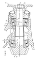
- A differential gear, in which a pinion gear-side portion (free end portion) of a pinion shaft is supported on an inner peripheral surface of a case by this double row rolling bearing, will be described with reference to
Fig. 11 . - The
differential gear 1 includes thedifferential case 2. Thedifferential case 2 comprises afront case 3 and a rear case 4, and the twocases 3 and 4 are joined together by bolt/nut arrangements 2a. - Bearing-mounting
annular walls front case 3. Thedifferential case 2 contains a differentialspeed change mechanism 5 interlocking right and left wheels in a differential manner, and thepinion shaft 7 having apinion gear 6. - The
pinion gear 6 is in mesh with aring gear 8 of the differentialspeed change mechanism 5. - A
shaft portion 9 of thepinion shaft 7 is stepped to increase in diameter toward thepinion gear 6. A pinion gear-side portion of theshaft portion 9 of thepinion shaft 7 is rotatably supported on theannular wall 27A of thefront case 3 through the double row rolling bearing 10. - An anti-pinion-gear-side portion (remote from the pinion gear 6) of the
shaft portion 9 of thepinion shaft 7 is rotatably supported on theannular wall 27B of thefront case 3 through a doublerow rolling bearing 25. - The
front case 3 has anoil circulating passageway 40 formed between its outer wall and theannular wall 27A, and anoil inlet 41 of theoil circulating passageway 40 is open toward thering gear 8, and anoil outlet 42 of theoil circulating passageway 40 is open to a region between theannular walls - A
closure plate 37 is inserted into thefront case 3 through a smaller-diameter opening thereof, and is fitted on theshaft portion 9 of thepinion shaft 7. - A
barrel portion 44 of acompanion flange 43 is spline-fitted on theshaft portion 9, and an end surface of thisbarrel portion 44 is held against theclosure plate 37. Anoil seal 46 is mounted on thebarrel portion 44 of thecompanion flange 43. - A
seal protection cup 47 is attached to the smaller-diameter opening portion of thefront case 3. - A
nut 49 is threaded on a threadedportion 48 of theshaft portion 9, thereby imparting a predetermined preload torows rows 32 and 33 of the double row rolling bearing 25. - In the above construction, the
nut 49 is threaded on the threadedportion 48, so that aninner ring 13 of the double row rolling bearing 10 and aninner ring 14 of the doublerow rolling bearing 25 are held between an end face of thepinion gear 6 and an end surface of thecompanion flange 43 in the axial direction, thereby imparting the predetermined preload to therows rows 32 and 33 of rolling elements of the double row rolling bearing 25 through theclosure plate 37 and aplastic spacer 23. - Here, the double row rolling bearing 10 and the double row rolling bearing 25 are provided respectively on at least two axially-spaced portions, that is, the pinion gear-side portion and the anti-pinion-gear-side portion of the
pinion shaft 7, and jointly form a rolling bearing apparatus supporting thepinion shaft 7 on theannular walls - The conventional double row rolling bearing 10 will now be described with reference to
Fig. 12 . This doublerow rolling bearing 10 is a double row angular contact ball bearing, and comprises anouter ring 11 having a larger-diameter raceway 11a and a smaller-diameter raceway 11b which are arranged in two rows in the axial direction, theinner ring 13 having a larger-diameter raceway 13a and a smaller-diameter raceways 13b which are arranged in two rows in the axial direction and are opposed respectively to the larger-diameter raceway 11a and the smaller-diameter raceway 11b in the radial direction, the larger-diameter row 17 of rolling elements disposed between the larger-diameter raceways diameter row 18 of rolling elements disposed between the smaller-diameter raceways diameter cage 19 holding the larger-diameter row 17 of rolling elements, and a smaller-diameter cage 20 holding the smaller-diameter row 18 of rolling elements. - In this double row rolling bearing 10, the inclinations of contact angles of the larger-diameter and smaller-
diameter rows - Among the bearing parts of the double row rolling bearing 10, the
inner ring 13, therows cages inner ring assembly 21, and thisinner ring assembly 21 is inserted into theouter ring 11 through a larger-diameter opening thereof to be mounted therein. - Namely, the
outer ring 11 is fixed to an inner peripheral surface of theannular wall 27A with its axis disposed horizontally. Theinner ring assembly 21 is fitted on thepinion shaft 7. Thepinion shaft 7 having theinner ring assembly 21 fitted thereon is inserted horizontally into the larger-diameter opening of theouter ring 11, thereby assembling theouter ring 11 and theinner ring assembly 21 together in the horizontal direction. By doing so, the pinion gear-side portion of thepinion shaft 7 can be supported on theannular wall 27A through the double row rolling bearing 10. - However, the double row rolling bearing 10 of the above construction has the following problems.
- These problems will be described with reference to
Figs. 13 and14 . In the drawings, the upward-downward direction is defined as the vertical direction, and the right-left direction is defined as the horizontal direction. Theouter ring 11, thepinion shaft 7 and theinner ring 13 of theinner ring assembly 21 have theirrespective axes 31 coinciding with one another.Fig. 13 shows a condition before theinner ring assembly 21 is mounted in theouter ring 11. Theouter ring 11 is mounted on the inner peripheral surface of theannular wall 27A (that is, the inner peripheral surface of the case) with its axis disposed horizontally. On the other hand, theinner ring assembly 21 is fitted on thepinion shaft 7. The distance from theaxis 31 of theouter ring 11 to a vertically-lower portion of an innerperipheral edge 11c of the larger-diameter opening of theouter ring 11 is represented by D0. - In the
inner ring assembly 21, therows raceways inner ring 13, respectively, and are held by thecages - In this condition, any load, that is, any external force, acts on the
rows row 17 of rolling elements and theraceway 13a of theinner ring 13, and also a radial clearance exists between therow 18 of rolling elements and theraceway 13b of theinner ring 13. Therefore, each of therolling element rows - Namely, the
rolling element row 17 as well as therolling element row 18 drops downward in an amount corresponding to the radial clearance. As a result, the vertical distance D1 from theaxis 31 to a vertically-lowermost end of the larger-diameter row 17 of rolling elements often becomes larger as compared with the vertical distance D0 from theaxis 31 of theouter ring 31 to the vertically-lower portion of the innerperipheral edge 11c of the larger-diameter opening of theouter ring 11. - In the case where this distance relation is established, the larger-
diameter row 17 of rolling elements are caused to abut against the innerperipheral edge portion 11c of the larger-diameter opening of theouter ring 11 when the pinion'shaft 7 is inserted into theouter ring 11 through the larger-diameter opening thereof as shown inFig. 14 . - The inner
peripheral edge 11c of the larger-diameter opening of theouter ring 11 has a generally right-angled corner-shape, and therefore when the speed of mounting (or inserting) of thepinion shaft 7 into the larger-diameter opening of theouter ring 11 is high, or when this mounting force is high, there is a possibility that the rolling elements forming therolling element row 17 are easily damaged at their surfaces by the innerperipheral edge 11c of the larger-diameter opening of theouter ring 11. - And besides, when those rolling elements of the
rolling element row 17 which have been damaged at their surfaces roll on theraceway 13a of theinner ring 13 at high speed, a large vibration and sound are produced, and also theraceway 13a of theinner ring 13 is subjected to damage such as flaking, etc., which invites a shortened life of the double row rolling bearing 10 at a premature stage. - Patent Literature 1:
JP-A-9-105450 - Patent Literature 2:
JP-A-10-220468 - Patent Literature 3:
JP-A-2004-190728 - Therefore, the problem that this invention is to solve is to provide a construction in which the dropping of the larger-diameter row of rolling elements is limited so as to prevent the rolling elements from abutting against the inner peripheral edge of the larger-diameter opening of the outer ring at the time when the inner ring assembly is inserted into the outer ring through the larger-diameter opening thereof to be mounted in the outer ring.
- According to the present invention, there is provided a double row rolling bearing for supporting a pinion shaft wherein an outer ring is fixed to an inner peripheral surface of a case with its axis disposed horizontally, and an inner ring assembly is fitted on a pinion shaft, and is inserted, together with the pinion shaft, horizontally into the outer ring through a larger-diameter opening of the outer ring, and is mounted in the outer ring; characterized in that the outer ring has a larger-diameter raceway and a smaller-diameter raceway which are formed in two rows on an inner peripheral surface thereof; and the inner ring assembly comprises an inner ring having a larger-diameter raceway and a smaller-diameter raceway which are formed in two rows on an outer peripheral surface thereof and are opposed respectively to the larger-diameter and smaller-diameter raceways of the outer ring in a radial direction, a larger-diameter row of rolling elements disposed between the larger-diameter raceways, a smaller-diameter row of rolling elements disposed between the smaller-diameter raceways, a larger-diameter cage holding the larger-diameter row of rolling elements, and a smaller-diameter cage holding the smaller-diameter row of rolling elements; and the larger-diameter cage has a flange-like drop limitation portion extending radially inwardly from an axially-inner end portion thereof, and the drop limitation portion prevents the larger-diameter row of rolling elements from dropping in an amount exceeding a predetermined value.
- The double row rolling bearing may be provided at the pinion gear-side portion of the pinion shaft or may be provided at each of the pinion gear-side and anti-pinion-gear-side portions of the pinion shaft.
- In the invention, there is provided the drop limitation portion, and therefore the inner ring assembly can be inserted into the outer ring through the larger-diameter opening thereof to be mounted therein without causing the larger-diameter row of rolling elements to abut against an inner peripheral edge of the larger-diameter opening of the outer ring.
- As a result, in the above mounting operation, the rolling elements will not be damaged by the inner peripheral edge of the larger-diameter opening of the outer ring, and therefore a large rolling sound will not be generated, and also a larger-diameter raceway of the inner ring will not be subjected to damage such as flaking, etc., thereby achieving a long life of the double row rolling bearing.
- According to another aspect of the invention, there is provided a rolling bearing apparatus wherein a pinion shaft having a pinion gear fixed to its free end portion is supported on an inner peripheral surface of a case of a differential gear, a transfer apparatus or the like of an automobile by at least two bearings disposed respectively at a pinion gear-side portion and an anti-pinion-gear-side portion of the pinion shaft which are spaced from each other in an axial direction;
characterized in that the pinion gear-side bearing is the above-mentioned double row rolling bearing, and the outer ring of the double row rolling bearing is fixed to the inner peripheral surface of the case with its larger-diameter opening directed toward the pinion gear, and the inner ring assembly is inserted into the outer ring through the larger-diameter opening thereof to be mounted in the outer ring. - In the present invention, the outer ring is fixed to the inner peripheral surface of the case with its axis disposed horizontally, and the inner ring assembly is fitted on the pinion shaft, and is inserted, together with the pinion shaft, horizontally into the outer ring through the larger-diameter opening of the outer ring, and is mounted in the outer ring. In this mounting operation, the dropping of the larger-diameter row of rolling elements downward in the vertical direction is limited by the drop limitation portion, so that the inner ring assembly can be mounted in the outer ring without causing the rolling elements to abut against the inner peripheral edge of the larger-diameter opening of the outer ring.
-
-
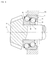
Fig. 1 is a cross-sectional view of a preferred embodiment of a double row rolling bearing of the present invention. -
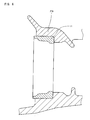
Fig. 2 is a cross-sectional view showing a condition in which an inner ring assembly of the double row rolling bearing is fitted on a pinion shaft, and an outer ring of the double row rolling bearing is fixed to an annular wall. -
Fig. 3 is a cross-sectional view showing a condition before the inner ring assembly is mounted in the outer ring. -
Fig. 4 is a cross-sectional view showing the process of mounting the inner ring assembly in the outer ring. -
Fig. 5 is a cross-sectional view showing a condition in which the inner ring assembly is mounted in the outer ring. -
Fig. 6 is a view showing a step of a method of mounting a preferred embodiment of a rolling bearing apparatus of the invention. -
Fig. 7 is a view showing the next step of the method of mounting the rolling bearing apparatus of the embodiment. -
Fig. 8 is a view showing the next step of the method of mounting the rolling bearing apparatus of the embodiment. -
Fig. 9 is a view showing the next step of the method of mounting the rolling bearing apparatus of the embodiment. -
Fig. 10 a view showing a final step of the method of mounting the rolling bearing apparatus of the embodiment. -
Fig. 11 is a cross-sectional view of a differential gear incorporating conventional double row rolling bearings therein. -
Fig. 12 is a cross-sectional view of the conventional double row rolling bearing. -
Fig. 13 is a cross-sectional view showing a condition before an inner ring assembly is mounted in an outer ring. -
Fig. 14 is a cross-sectional view showing the process of mounting the inner ring assembly in the outer ring. - A preferred embodiment of a double row rolling bearing of the present invention will now be described with reference to the accompanying drawings. In
Fig. 1 , those portions similar to those of the above-mentioned conventional example will be designated by identical reference numerals, respectively, and description thereof will be omitted. - In the double
row rolling bearing 10 of this embodiment, anouter ring 11 is fixed to an inner peripheral surface of anannular wall 27A with its axis disposed horizontally. Aninner ring assembly 21 is fitted on apinion shaft 7, and is inserted horizontally, together with thepinion shaft 7, into a larger-diameter opening of theouter ring 11, and is mounted in theouter ring 11. - In this double
row rolling bearing 10, an axially-inner end of a larger-diameter cage 19 of theinner ring assembly 21 is extended radially inwardly to form an annular flange portion serving as adrop limitation portion 30 . In the process of mounting theinner ring assembly 21 in theouter ring 11, this flange portion (the drop limitation portion 30) is caused to abut against an outer peripheral surface of theinner ring 13 to limit the dropping of the larger-diameter cage 19 downward in a vertical direction, thereby preventing a radial clearance at a vertically-upper side of a larger-diameter row 17 of rolling elements from becoming smaller than a predetermined value. Thisdrop limitation portion 30 may be formed integrally with the larger-diameter cage 19 or may be formed separately from thecage 19. A generally uniform clearance G1 exists between an innerperipheral surface 35 of thedrop limitation portion 30 and the outerperipheral surface 33 of theinner ring 13 in the vertical direction. - The
drop limitation portion 30 will be described with reference toFig. 2. Fig. 2 shows a condition in which theinner ring assembly 21 is merely fitted on thepinion shaft 7, and is not yet mounted in theouter ring 11. For better understanding of the drop limitation effect by thedrop limitation portion 30, an imaginary line indicates a dropped condition obtained when thedrop limitation portion 30 is not provided. - A smaller-
diameter cage 20 of theinner ring assembly 21 is not provided with suchdrop limitation portion 30, and therefore thiscage 20, together with a smaller-diameter row 18 of rolling elements, drop downward in the vertical direction by an amount equal to a radial clearance, and the radial clearance is eliminated at a vertically-upper side of the smaller-diameter row 18 of rolling elements, so that the radial clearance at a vertically-lower side increases. - On the other hand, although the larger-
diameter cage 19 of theinner ring assembly 21 also drops in the vertical direction, the inner peripheral surface of the vertically-upper portion of thedrop limitation portion 30 of thecage 19 abuts against the outer peripheral surface of the vertically-upper portion of theinner ring 13. Therefore, the amount of dropping of the larger-diameter cage 19 downward in the vertical direction is reduced by a limitation length (i.e., a height or radial dimension) of thedrop limitation portion 30 as compared with the case where thedrop limitation portion 30 is not provided as indicated by the imaginary line. - The limitation length of the
drop limitation portion 30 is so determined as to satisfy a formula, D1 ≤ D0, where D0 represents the distance (first distance) from theaxis 31 of theouter ring 11 to a vertically-lower portion of an innerperipheral edge 11c of the larger-diameter opening of theouter ring 11, and D1 represents the distance (second distance) from theaxis 31 to a vertically-lower end of the larger-diameter row 17 of rolling elements. - By thus determining the limitation length, the
inner ring assembly 21 can be inserted horizontally into theouter ring 11 through the larger-diameter opening thereof to be mounted in theouter ring 11 without causing the larger-diameter row 17 of rolling elements to abut against the innerperipheral edge 11c of the larger-diameter opening of theouter ring 11 at their vertically-lower portions. - The limitation length of the
drop limitation portion 30 and the above formula will be described with reference toFigs. 3 to 5 in connection with the description of the process of mounting the inner ring assembly 21 (fitted on the pinion shaft 7) in theouter ring 11 through the larger-diameter opening thereof. - As shown in
Fig. 3 , theinner ring assembly 21 is fitted on thepinion shaft 7. Theouter ring 11 is fixed to the inner peripheral surface of theannular wall 27A. Theaxes 31 of theouter ring 11, thepinion shaft 7 and theinner ring 13 of theinner ring assembly 21 coincide with one another in the horizontal direction. - As described above, the length of the
drop limitation portion 30 is so determined as to satisfy the formula, D1 ≤ D0, where D0 represents the distance (first distance) from theaxis 31 of theouter ring 11 to the vertically-lower portion of the innerperipheral edge 11c of the larger-diameter opening of theouter ring 11, and D1 represents the distance (second distance) from theaxis 31 to the vertically-lowermost end of the larger-diameter row 17 of rolling elements. Therefore, even when the larger-diameter cage 19 is moved downward in the vertical direction because of its deadweight and the deadweight of therow 17 of rolling elements, this movement is limited by thedrop limitation portion 30 designed to satisfy the formula, D1 ≤ D0. Incidentally, in the case where thedrop limitation portion 30 is not provided, the larger-diameter cage 19 drops in a larger amount as indicated in an imaginary line, so that the distance from theaxis 31 to the vertically-lowermost end of the larger-diameter row 17 of rolling elements is represented by D1' (> D0). - As a result, when the
inner ring assembly 21 is inserted into the larger-diameter opening of theouter ring 11 as shown inFig. 4 , the vertically-lowermost end of the larger-diameter row 17 of rolling elements will not abut against the vertically-lower portion of the innerperipheral edge 11c of the larger-diameter opening of theouter ring 11, and can be mounted onto a larger-diameter raceway 11a of theouter ring 11. As a result, theinner ring assembly 21 can be mounted in theouter ring 11 as shown inFig. 5 . On the other hand, in the case where thedrop limitation portion 30 is not provided, the distance from theaxis 31 to the vertically-lowermost end of the larger-diameter row 17 of rolling elements does not satisfy the above formula, and therefore the vertically-lowermost end of the larger-diameter row 17 of rolling elements are brought into abutting engagement with theinner peripheral.edge 11c of the larger-diameter opening of theouter ring 11 as described above for the conventional construction. - As described above, in this embodiment, the length of the
drop limitation portion 30 formed at the inner peripheral portion of the larger-diameter cage 19 is so determined that when theinner ring assembly 21 is inserted into the larger-diameter opening of theouter ring 11, the vertically-lowermost end of the larger-diameter row 17 of rolling elements will not be brought into abutting engagement with the vertically-lower portion of the innerperipheral edge 11c of the larger-diameter opening of theouter ring 11. Therefore, theinner ring assembly 21 can be inserted into the larger-diameter opening of theouter ring 11 without causing the larger-diameter row 17 of rolling elements to abut against the innerperipheral edge 11c of the larger-diameter opening of theouter ring 11. - As a result, in this embodiment, the larger-
diameter row 17 of rolling elements, as well as the smaller-diameter row 18 of rolling elements, will not be damaged by the innerperipheral edge 11c of the larger-diameter opening of theouter ring 11 during the above mounting operation. As a result, a large rolling sound will not be generated, and also a larger-diameter raceway 13a of theinner ring 13 will not be subjected to damage such as flaking, etc. - Here, the showing of the whole of a differential gear incorporating the double row rolling bearing of this embodiment therein is omitted. In the double
row rolling bearing 10 incorporated in the differential gear, thedrop limitation portion 30 of the larger-diameter cage 19 is held out of contact with the outer peripheral surface of theinner ring 13, and therefore thisdrop limitation portion 30 will not adversely affect the function of the differential gear. - Next, a method of mounting a preferred embodiment of a rolling bearing apparatus of the invention will be described with reference to
Figs. 6 to 10 . An anti-pinion-gear-side doublerow rolling bearing 25 is a double row angular contact ball bearing, and comprises anouter ring 12 having a larger-diameter raceway 12a and a smaller-diameter raceway 12b which are arranged in two tow in the axial direction, aninner ring 14 having a larger-diameter raceway 14a and a smaller-diameter raceway 14b which are arranged in two rows in the axial direction and are opposed respectively to the larger-diameter raceway 12a and the smaller-diameter raceway 12b in the radial direction, a larger-diameter row 32 of rolling elements disposed between the larger-diameter raceways diameter row 33 of rolling elements disposed between the smaller-diameter raceways diameter cage 34 holding the larger-diameter row 32 of rolling elements, and a smaller-diameter cage 35 holding the smaller-diameter row 33 of rolling elements. - In the double
row rolling bearing 25, theinner ring 14, therows 32 and 33 of rolling elements and thecages inner ring assembly 23, and thisinner ring assembly 23 is inserted into theouter ring 12 through a larger-diameter opening thereof to be mounted in theouter ring 12. In the doublerow rolling bearing 25, the inclinations of contact angles of the larger-diameter and smaller-diameter rows 32 and 33 of rolling elements for the respective raceways (12a and 14a) and (12b and 14b) are in the same direction. - Namely, the double
row rolling bearings outer ring 11 of the doublerow rolling bearing 10 and a back face of theouter ring 12 of the doublerow rolling bearing 25 are caused to abut respectively against radially inwardly-directed step portions ofannular walls inner ring 13 of the doublerow rolling bearing 10 is caused to abut against an inner end face of apinion gear 6, and a back face of theinner ring 14 of the doublerow rolling bearing 25 is caused to abut against an inner end face of acompanion flange 43, and further aspacer 7 is held between opposed front faces of the twoinner rings bearings nut 49 is tightened, thereby setting the preload. - First, as shown in
Fig. 6 , the outer ring (pinion gear-side outer ring) 11 of the pinion gear-side doublerow rolling bearing 10 is fixed to theannular wall 27A (pinion gear-side inner peripheral surface of the case) with its larger-diameter opening directed toward the pinion gear 6 (First Step). - Then, as shown in
Fig. 7 , the outer ring (anti-pinion-gear-side outer ring) 12 of the anti-pinion-gear-side doublerow rolling bearing 25 is fixed to theannular wall 27B (anti-pinion-gear-side inner peripheral surface of the case) with its larger-diameter opening directed away from the pinion gear 6 (Second Step). - Then, as shown in
Fig. 8 , the inner ring assembly (pinion gear-side inner ring assembly) 21 of the pinion gear-side doublerow rolling bearing 10 is fitted on a pinion gear-side portion of thepinion shaft 7 with the smaller-diameter end of theinner ring 13 directed toward the larger-diameter opening of the pinion gear-side outer ring 11 (Third Step, seeFig. 3 ). - Then, as shown in
Fig. 9 , thepinion shaft 7 is passed through the pinion gear-sideouter ring 11 from the pinion gear-side, and is further passed through the anti-pinion-gear-sideouter ring 12, thereby mounting the pinion gear-sideinner ring 13 in the pinion gear-side outer ring 11 (Fourth Step, seeFigs. 4 and5 ). - Finally, as shown in
Fig. 10 , the inner ring assembly (anti-pinion-gear-side inner ring assembly) 23 of the anti-pinion-gear-side doublerow rolling bearing 25 is mounted in the anti-pinion-gear-sideouter ring 12 from the anti-pinion-gear side of the pinion shaft 7 (Fifth Step).. - Thus, the mounting of the rolling bearing apparatus of this embodiment in the differential gear is completed.
Claims (4)
- A double row rolling bearing for supporting a pinion shaft, wherein an outer ring is fixed to an inner peripheral surface of a case with its axis disposed horizontally, and an inner ring assembly is fitted on a pinion shaft, and is inserted, together with the pinion shaft, horizontally into the outer ring through a larger-diameter opening of the outer ring, and is mounted in the outer ring; characterized in that:the outer ring has a larger-diameter raceway and a smaller-diameter raceway which are formed in two rows on an inner peripheral surface thereof; andthe inner ring assembly comprises an inner ring having a larger-diameter raceway and a smaller-diameter raceway which are formed in two rows on an outer peripheral surface thereof and are opposed respectively to the larger-diameter and smaller-diameter raceways of the outer ring in a radial direction, a larger-diameter row of rolling elements disposed between the larger-diameter raceways, a smaller-diameter row of rolling elements disposed between the smaller-diameter raceways, a larger-diameter cage holding the larger-diameter row of rolling elements, and a smaller-diameter cage holding the smaller-diameter row of rolling elements; andthe larger-diameter cage has a flange-like drop limitation portion extending radially inwardly from an axially-inner end portion thereof, and the drop limitation portion prevents the larger-diameter row of rolling elements from dropping in an amount exceeding a predetermined value.
- A rolling bearing apparatus wherein a pinion shaft having a pinion gear fixed to its free end portion is supported on an inner peripheral surface of a case of a differential gear, a transfer apparatus or the like of an automobile by at least two bearings disposed respectively at a pinion gear-side portion and an anti-pinion-gear-side portion of the pinion shaft which are spaced from each other in an axial direction;
characterized in that the pinion gear-side bearing is a double row rolling bearing as defined in claim 1, and the outer ring of the double row rolling bearing is fixed to the inner peripheral surface of the case with its larger-diameter opening directed toward the pinion gear, and at the time when the inner ring assembly is inserted into the outer ring through the larger-diameter opening thereof to be mounted in the outer ring, an inner peripheral surface of a vertically-upper portion of the drop limitation portion abuts against the outer peripheral surface of the inner ring. - A rolling bearing apparatus wherein a pinion shaft having a pinion gear fixed to its free end portion is supported on an inner peripheral surface of a case of a differential gear, a transfer apparatus or the like of an automobile by at least two bearings disposed respectively at a pinion gear-side portion and an anti-pinion-gear-side portion of the pinion shaft which are spaced from each other in an axial direction; characterized in that the anti-pinion-gear-side bearing is a double row rolling bearing as defined in claim 1, and the outer ring of the double row rolling bearing is fixed to the inner peripheral surface of the case with its larger-diameter opening directed away from the pinion gear, and at the time when the inner ring assembly is inserted into the outer ring through the larger-diameter opening thereof to be mounted in the outer ring, an inner peripheral surface of a vertically-upper portion of the drop limitation portion abuts against the outer peripheral surface of the inner ring.
- A method of mounting a rolling bearing apparatus wherein a pinion shaft having a pinion gear fixed to its free end portion is supported by two bearings disposed respectively on a pinion gear-side inner peripheral surface and an anti-pinion-gear-side inner peripheral surface of a case of a differential gear, a transfer apparatus or the like of an automobile which are spaced from each other in an axial direction, and each of the two bearings is a double row rolling bearing as defined in claim 1; characterized in that the method comprises:a first step of fixing the pinion gear-side outer ring of the pinion gear-side double row rolling bearing to the pinion gear-side inner peripheral surface of the case with its larger-diameter opening directed toward the pinion gear;a second step of fixing the anti-pinion-gear-side outer ring of the anti-pinion-gear-side double row rolling bearing to the anti-pinion-gear-side inner peripheral surface of the case with its larger-diameter opening directed away from the pinion gear;a third step of fitting the pinion gear-side inner ring assembly of the pinion gear-side double row rolling bearing on the pinion gear-side portion of the pinion shaft with a smaller-diameter portion of the inner ring directed toward the larger-diameter opening of the pinion gear-side outer ring while an inner peripheral surface of a vertically-upper portion of the drop limitation portion abuts against the outer peripheral surface of the inner ring;a fourth step of passing the pinion shaft through the pinion gear-side outer ring from the pinion gear side and further passing the pinion shaft through the anti-pinion-gear-side outer ring, thereby mounting the pinion gear-side inner ring assembly in the pinion gear-side outer ring; anda fifth step of mounting the anti-pinion-gear-side inner ring assembly of the anti-pinion-gear-side double row rolling bearing in the anti-pinion-gear-side outer ring from the anti-pinion-gear side while an inner peripheral surface of a vertically-upper portion of the drop limitation portion abuts against the outer peripheral surface of the inner ring; and thatafter the first and second steps are carried out in random order, the third to fifth steps are sequentially carried out.
Applications Claiming Priority (2)
| Application Number | Priority Date | Filing Date | Title |
|---|---|---|---|
| JP2006102212A JP4862458B2 (en) | 2006-04-03 | 2006-04-03 | Double-row rolling bearing for pinion shaft support and rolling bearing device provided with the same |
| PCT/JP2007/057418 WO2007116869A1 (en) | 2006-04-03 | 2007-04-02 | Double-row rolling bearing for supporting pinion shaft, and rolling bearing device with the same |
Publications (1)
| Publication Number | Publication Date |
|---|---|
| EP2003351A1 true EP2003351A1 (en) | 2008-12-17 |
Family
ID=38581159
Family Applications (1)
| Application Number | Title | Priority Date | Filing Date |
|---|---|---|---|
| EP07740854A Withdrawn EP2003351A1 (en) | 2006-04-03 | 2007-04-02 | Double-row rolling bearing for supporting pinion shaft, and rolling bearing device with the same |
Country Status (4)
| Country | Link |
|---|---|
| US (1) | US8371759B2 (en) |
| EP (1) | EP2003351A1 (en) |
| JP (1) | JP4862458B2 (en) |
| WO (1) | WO2007116869A1 (en) |
Cited By (1)
| Publication number | Priority date | Publication date | Assignee | Title |
|---|---|---|---|---|
| DE102010062479A1 (en) * | 2010-12-06 | 2012-06-06 | Aktiebolaget Skf | Rolling bearing and cage for a rolling bearing |
Families Citing this family (15)
| Publication number | Priority date | Publication date | Assignee | Title |
|---|---|---|---|---|
| JP5803234B2 (en) * | 2010-04-19 | 2015-11-04 | 日本精工株式会社 | Tandem angular contact ball bearings |
| DE102012214023B3 (en) * | 2012-08-08 | 2014-01-23 | Siemens Aktiengesellschaft | Planetary gear with planet carrier |
| DE102012217385B4 (en) * | 2012-09-26 | 2014-10-09 | Schaeffler Technologies Gmbh & Co. Kg | Pinion shaft bearing |
| JP6427928B2 (en) * | 2014-04-15 | 2018-11-28 | 株式会社ジェイテクト | Double row ball bearing and shaft support device |
| US9382940B2 (en) | 2014-05-12 | 2016-07-05 | Schaeffler Technologies AG & Co. KG | Triple race angular contact bearing |
| US20160327093A1 (en) * | 2015-05-06 | 2016-11-10 | Michael D. Johns | Bearing for use in directional drilling |
| DE102015014087B4 (en) * | 2015-11-03 | 2017-11-09 | Sew-Eurodrive Gmbh & Co Kg | transmission |
| ITUB20159160A1 (en) * | 2015-12-22 | 2017-06-22 | Ge Avio Srl | ASSEMBLY PROCEDURE FOR MOUNTING A VOLVENT BEARING ON A GEAR SHAFT, AND GEAR ASSEMBLY OBTAINABLE THROUGH THIS PROCEDURE |
| US12031581B1 (en) * | 2017-07-10 | 2024-07-09 | Hubbell Incorporated | Bearing assembly for electrical switch |
| CN111288085B (en) * | 2018-12-10 | 2022-02-15 | 上银科技股份有限公司 | Ball cages for ball bearings |
| DE102019123254A1 (en) * | 2019-08-30 | 2020-09-03 | Schaeffler Technologies AG & Co. KG | Angular contact ball bearings, device for positioning balls of the angular contact ball bearing and method for dismantling and assembling the angular contact ball bearing |
| CN113788398A (en) * | 2021-09-10 | 2021-12-14 | 中船重工电机科技股份有限公司 | Vertical shrink-fit large-diameter double-row self-aligning bearing tooling on the motor shaft |
| WO2023076798A2 (en) * | 2021-10-27 | 2023-05-04 | Atieva, Inc. | Lubrication and cooling system for rotatable components |
| JP7798121B2 (en) * | 2022-01-12 | 2026-01-14 | 株式会社ジェイテクト | ball bearing |
| WO2023135669A1 (en) * | 2022-01-12 | 2023-07-20 | 株式会社ジェイテクト | Ball bearing |
Family Cites Families (15)
| Publication number | Priority date | Publication date | Assignee | Title |
|---|---|---|---|---|
| US1325113A (en) * | 1919-12-16 | Ball-bearing | ||
| US1643982A (en) * | 1924-07-11 | 1927-10-04 | New Departure Mfg Co | Bearing |
| US3792625A (en) * | 1971-06-28 | 1974-02-19 | Skf Ind Trading & Dev | Pinion gear transmission |
| US4136916A (en) * | 1977-06-27 | 1979-01-30 | The Timken Company | Unitized single row tapered roller bearing |
| US4722617A (en) * | 1987-07-17 | 1988-02-02 | The Torrington Company | Ball bearing assembly |
| JPH09105450A (en) | 1996-07-15 | 1997-04-22 | Nippon Seiko Kk | Lubricating device for differential bearings |
| JPH10220468A (en) | 1997-02-03 | 1998-08-21 | Tochigi Fuji Ind Co Ltd | Bearing holding structure |
| JP3907820B2 (en) * | 1998-03-25 | 2007-04-18 | Ntn株式会社 | Angular contact ball bearings |
| US6386764B1 (en) * | 2000-09-07 | 2002-05-14 | The Timken Company | Bearing unitized for handling |
| JP2003314541A (en) * | 2002-04-19 | 2003-11-06 | Koyo Seiko Co Ltd | Double row rolling bearing |
| DE10239742B4 (en) * | 2002-05-10 | 2011-07-28 | Schaeffler Technologies GmbH & Co. KG, 91074 | Single-sided double angular contact ball bearings |
| US7059777B2 (en) * | 2002-09-30 | 2006-06-13 | Koyo Seiko Co., Ltd. | Assembly for ball bearing with double raceway and method of manufacturing ball bearing with double raceway |
| JP4517672B2 (en) * | 2004-02-20 | 2010-08-04 | 株式会社ジェイテクト | Bearing device for pinion shaft support |
| JP2005233406A (en) * | 2004-02-23 | 2005-09-02 | Koyo Seiko Co Ltd | Double-row slant contact ball bearing and its preloading method |
| DE102004013804A1 (en) * | 2004-03-20 | 2005-10-06 | Fag Kugelfischer Ag | Cage for angular contact ball bearings |
-
2006
- 2006-04-03 JP JP2006102212A patent/JP4862458B2/en not_active Expired - Fee Related
-
2007
- 2007-04-02 EP EP07740854A patent/EP2003351A1/en not_active Withdrawn
- 2007-04-02 US US12/225,923 patent/US8371759B2/en not_active Expired - Fee Related
- 2007-04-02 WO PCT/JP2007/057418 patent/WO2007116869A1/en not_active Ceased
Non-Patent Citations (1)
| Title |
|---|
| See references of WO2007116869A1 * |
Cited By (3)
| Publication number | Priority date | Publication date | Assignee | Title |
|---|---|---|---|---|
| DE102010062479A1 (en) * | 2010-12-06 | 2012-06-06 | Aktiebolaget Skf | Rolling bearing and cage for a rolling bearing |
| US8864386B2 (en) | 2010-12-06 | 2014-10-21 | Aktiebolaget Skf | Roller bearing and cage for a roller bearing |
| DE102010062479B4 (en) * | 2010-12-06 | 2016-01-14 | Aktiebolaget Skf | Rolling bearing and cage for a rolling bearing |
Also Published As
| Publication number | Publication date |
|---|---|
| US20100202721A1 (en) | 2010-08-12 |
| WO2007116869A1 (en) | 2007-10-18 |
| JP2007278324A (en) | 2007-10-25 |
| US8371759B2 (en) | 2013-02-12 |
| JP4862458B2 (en) | 2012-01-25 |
Similar Documents
| Publication | Publication Date | Title |
|---|---|---|
| US8371759B2 (en) | Double row rolling bearing for supporting pinion shaft and rolling bearing apparatus provided with the same | |
| EP1840391B1 (en) | Rolling bearing device with a double row rolling contact bearing for supporting a pinion shaft | |
| EP1498621B1 (en) | Pinion shaft with supporting bearing device therefor | |
| EP2615320B1 (en) | A bearing adjuster assembly | |
| JP5366665B2 (en) | Wheel bearing device | |
| WO2003040578A1 (en) | Bearing device for supporting pinion shaft | |
| WO2010147135A1 (en) | Wheel bearing | |
| EP1777079A1 (en) | Wheel drive unit | |
| US7597482B2 (en) | Skew contact double row ball bearing and bearing device for supporting pinion shaft | |
| EP2706269A1 (en) | Rotating machine with pulley and built-in one-way clutch | |
| US7635226B2 (en) | Bearing apparatus for a wheel of vehicle | |
| JP2011027130A (en) | Bearing device for wheel | |
| US7909515B2 (en) | Double row ball bearing and differential gear device | |
| JP4986116B2 (en) | Wheel bearing device | |
| US7690449B2 (en) | Output yoke shaft and assembly | |
| JP5187877B2 (en) | Wheel bearing device | |
| EP2587078A1 (en) | Wheel bearing device | |
| US11193573B1 (en) | Differential pinion bearing assembly | |
| EP1889734B1 (en) | Axle bearing apparatus and method of producing hub shaft for driving wheel bearing apparatus | |
| JP4868891B2 (en) | Wheel bearing device | |
| JP4998980B2 (en) | Wheel bearing device | |
| JP4936739B2 (en) | Wheel bearing device | |
| JP2007218290A (en) | Wheel bearing device | |
| WO2012043706A1 (en) | Drive wheel bearing unit and method for manufacturing same | |
| JP2008045674A (en) | Wheel bearing device |
Legal Events
| Date | Code | Title | Description |
|---|---|---|---|
| PUAI | Public reference made under article 153(3) epc to a published international application that has entered the european phase |
Free format text: ORIGINAL CODE: 0009012 |
|
| 17P | Request for examination filed |
Effective date: 20081002 |
|
| AK | Designated contracting states |
Kind code of ref document: A1 Designated state(s): DE FR |
|
| DAX | Request for extension of the european patent (deleted) | ||
| RBV | Designated contracting states (corrected) |
Designated state(s): DE FR |
|
| STAA | Information on the status of an ep patent application or granted ep patent |
Free format text: STATUS: THE APPLICATION HAS BEEN WITHDRAWN |
|
| 18W | Application withdrawn |
Effective date: 20140512 |