EP2003304A1 - Piston with a piston bowl for a combustion engine and method for fuel-mixture generation using an injection device and such a piston - Google Patents
Piston with a piston bowl for a combustion engine and method for fuel-mixture generation using an injection device and such a piston Download PDFInfo
- Publication number
- EP2003304A1 EP2003304A1 EP07110323A EP07110323A EP2003304A1 EP 2003304 A1 EP2003304 A1 EP 2003304A1 EP 07110323 A EP07110323 A EP 07110323A EP 07110323 A EP07110323 A EP 07110323A EP 2003304 A1 EP2003304 A1 EP 2003304A1
- Authority
- EP
- European Patent Office
- Prior art keywords
- piston
- fuel
- trough
- convex portion
- injection
- Prior art date
- Legal status (The legal status is an assumption and is not a legal conclusion. Google has not performed a legal analysis and makes no representation as to the accuracy of the status listed.)
- Granted
Links
Images


Classifications
-
- F—MECHANICAL ENGINEERING; LIGHTING; HEATING; WEAPONS; BLASTING
- F02—COMBUSTION ENGINES; HOT-GAS OR COMBUSTION-PRODUCT ENGINE PLANTS
- F02B—INTERNAL-COMBUSTION PISTON ENGINES; COMBUSTION ENGINES IN GENERAL
- F02B23/00—Other engines characterised by special shape or construction of combustion chambers to improve operation
- F02B23/02—Other engines characterised by special shape or construction of combustion chambers to improve operation with compression ignition
- F02B23/06—Other engines characterised by special shape or construction of combustion chambers to improve operation with compression ignition the combustion space being arranged in working piston
- F02B23/0672—Omega-piston bowl, i.e. the combustion space having a central projection pointing towards the cylinder head and the surrounding wall being inclined towards the cylinder center axis
-
- F—MECHANICAL ENGINEERING; LIGHTING; HEATING; WEAPONS; BLASTING
- F02—COMBUSTION ENGINES; HOT-GAS OR COMBUSTION-PRODUCT ENGINE PLANTS
- F02B—INTERNAL-COMBUSTION PISTON ENGINES; COMBUSTION ENGINES IN GENERAL
- F02B23/00—Other engines characterised by special shape or construction of combustion chambers to improve operation
- F02B23/02—Other engines characterised by special shape or construction of combustion chambers to improve operation with compression ignition
- F02B23/06—Other engines characterised by special shape or construction of combustion chambers to improve operation with compression ignition the combustion space being arranged in working piston
- F02B23/0645—Details related to the fuel injector or the fuel spray
-
- Y—GENERAL TAGGING OF NEW TECHNOLOGICAL DEVELOPMENTS; GENERAL TAGGING OF CROSS-SECTIONAL TECHNOLOGIES SPANNING OVER SEVERAL SECTIONS OF THE IPC; TECHNICAL SUBJECTS COVERED BY FORMER USPC CROSS-REFERENCE ART COLLECTIONS [XRACs] AND DIGESTS
- Y02—TECHNOLOGIES OR APPLICATIONS FOR MITIGATION OR ADAPTATION AGAINST CLIMATE CHANGE
- Y02T—CLIMATE CHANGE MITIGATION TECHNOLOGIES RELATED TO TRANSPORTATION
- Y02T10/00—Road transport of goods or passengers
- Y02T10/10—Internal combustion engine [ICE] based vehicles
- Y02T10/12—Improving ICE efficiencies
Definitions
- the invention relates to a piston having a piston head and a piston recess provided in the piston crown, in particular for an internal combustion engine, which allows operation in two different operating modes, which - during operation of the internal combustion engine - is translationally movable along a piston longitudinal axis and in which the piston recess has an omega-shaped basic shape.
- the invention relates to a method for forming a fuel-air mixture using an injector and a piston of the aforementioned type, wherein at least one injection of fuel is made directly into the combustion chamber of an internal combustion engine by means of the injection device, wherein the combustion chamber the piston crown of the piston and a cylinder tube is mitbe interpersonal.
- the market share of small high-speed diesel engines is growing steadily. The reasons for this are on the one hand in the low fuel consumption and on the other hand in the comparatively good performance of modern diesel engines of the younger generations.
- the low fuel consumption results, among other things, from a high compression ratio and low charge cycle losses due to the quality control of the diesel engine.
- the nitrogen oxides contained in the exhaust can inherently - ie due to the lack of reducing agents - can not be reduced without additional measures.
- selective catalysts - so-called SCR catalysts - are used, in which targeted reducing agents are introduced into the exhaust gas to selectively reduce the nitrogen oxides.
- SCR catalysts - As a reducing agent in addition to ammonia and urea also unburned hydrocarbons are used. The latter is also called HC enrichment.
- the nitrogen oxides can also be counteracted with so-called nitrogen oxide storage catalysts.
- the nitrogen oxides are first collected during a storage phase in the catalytic converter, in order then to be reduced during a regeneration phase by means of a substoichiometric operation (for example ⁇ ⁇ 0.95) of the internal combustion engine.
- Storage catalytic converters require the combustion of a homogeneous mixture to avoid high levels of soot emissions, which is why they are suitable for lean-burn gasoline engines, but especially not for direct-injection diesel engines.
- An internal engine measure known from the prior art for reducing nitrogen oxide emissions consists in reducing the combustion temperatures, in particular the process peak temperatures. As the process temperatures decrease, the formation of nitrogen oxides also decreases.
- Lower process temperatures can be realized for example by the recycling of hot exhaust gas (EGR) and / or intercooling.
- EGR hot exhaust gas
- Another disadvantage of the direct injection diesel engine process is the soot emissions due to the inhomogeneity of the fuel-air mixture.
- regenerable particulate filters are used in the prior art, which filter the soot particles from the exhaust gas and store, these soot particles are intermittently burned in the regeneration of the filter.
- soot To comply with future limits, the formation of soot must already be counteracted during the combustion, which can be achieved by a sufficiently large excess of air and an optimized mixture formation with the greatest possible homogenization.
- the Otto engine method is characterized by a mixture compression, a homogeneous mixture, a spark ignition, and the quantity control, whereas the diesel engine process is characterized by an air compression, an inhomogeneous mixture, auto-ignition and quality control.
- LTC Low Temperature Combustion
- HCCI Homogeneous-Charge Compression Ignition
- CAI-process C ontrolled A uto- gnition I
- the fuel is burned in excess of air - that is, more than stoichiometrically.
- the lean-burn diesel engine has comparatively low nitrogen oxide emissions (NO x ) due to the highly diluted homogenized fuel-air mixture and the associated low combustion temperatures and also virtually no soot emissions due to the lean homogenized mixture.
- the thermal efficiency of the HCCI process is high because the homogenized mixture burns volumetrically, i. H. no diffusion flame propagates through the combustion chamber, but is ignited and burned in the entire combustion chamber almost simultaneously at a constant volume.
- the diesel engine HCCI process also has disadvantages similar to those of the Otto engine HCCI process.
- the main disadvantage of the HCCI method is that this method can not be used in all operating points of an internal combustion engine, so that the - already described above - benefits only in a small area of the engine map (load over speed) can be used.
- an internal combustion engine can not be operated exclusively by the HCCI method, but basically a hybrid drive is required, ie, an internal combustion engine, which allows operation in two different operating modes to the internal combustion engine in the operating points where the HCCI method fails to operate anyway.
- a conventional diesel engine process is used Use in which spreads a self-ignition, a diffusion flame in the combustion chamber.
- the HCCI method can not be used at high loads and high speeds.
- the restrictions in the application of the HCCI method arise in principle from the control of the ignition timing d. H. the auto-ignition and the control of the burning speed d. H. the burning process.
- the auto-ignition and the burning speed are very sensitive to changes in the temperature of the cylinder charge, changes in the air ratio and speed changes.
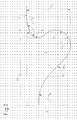
- the piston bowl 104 of a conventional piston 101 has according to FIG. 1 a concave portion 108, which serves to form the omega-shaped basic shape of the piston recess 104, wherein the piston longitudinal axis 102 facing trough surface 105 has two convex Partial regions 107a, 107b, of which a first portion 107a forms the trough edge 106 and a second portion 107b projects into the piston recess 104.
- the two convex portions 107a, 107b are connected to each other via a cylindrical wall portion.
- the fuel according to FIG. 1 injected in such a way that the injection jets 109 are directed to the second convex portion 107b, wherein the individual injection jets 109 split upon impact with the trough surface 105 in a plurality of divergent fuel partial beams, partially accelerated out of the piston recess 104 and partially deflected thereby mixed the fuel is spacious with the air in the combustion chamber, so that a good use of air is ensured.
- a disadvantage of this conventional method for mixture formation is that - arise on the one hand due to the very dynamic distribution of the fuel in the combustion chamber and on the other hand due to the small radius of curvature of the trough edge - turbulence in the fuel-air mixture, especially in the region of the trough edge at the transition into the Crushing zone, which in a few, locally narrow areas of the combustion chamber, the mixture formation progresses so far that local conditions for auto-ignition are present, whereas in many areas of the combustion chamber is still a very inhomogeneous mixture. For this reason, the self-ignition is initiated earlier than is desirable, in particular with regard to a good emission behavior of the internal combustion engine. It would be more advantageous to increase the ignition delay d. H. ignite later and further homogenize the mixture before initiating auto-ignition.
- Another object of the present invention is to provide a method of forming a fuel-air mixture using an injector and such a piston.
- the first sub-task is solved by a piston with piston crown and provided in the piston crown piston recess, in particular for an internal combustion engine, which allows operation in two different operating modes, which - during operation of the internal combustion engine - is translationally movable along a piston longitudinal axis and wherein the piston recess an omega-shaped Has basic shape and which is characterized in that the piston longitudinal axis facing trough surface of the Omega-shaped piston recess has a convex portion which projects into the piston recess and merges while maintaining the direction of curvature and forming a trough edge in the piston crown, said convex portion of a minimum radius of curvature r 2 , with r 2 ⁇ 0.02 d, where d indicates the piston diameter.
- the convex portion of the piston according to the invention has a larger radius of curvature compared to the prior art.
- the minimum radius of curvature r 2 is not less than 0.02 d, where d indicates the piston diameter.
- the emission behavior of the internal combustion engine is improved. Nitrogen oxide emissions and soot emissions are reduced.
- the field of application of the so-called LTC method can be extended to higher loads and higher speeds, since the auto-ignition is better controllable d. H. easier to control.
- the advantages of the LTC process can thus be used in another area of the engine map, which reduces nitrogen oxide emissions and soot emissions.
- the mixture formation is more spray-guided when using a conventional piston
- the mixture of the fuel with the combustion air is carried wall guided when using a piston according to the invention.
- the fuel is injected into the combustion chamber in such a way that the injection jet is directed in a targeted manner to a wall delimiting the combustion chamber, preferably into the depression provided in the piston crown.
- the fuel jet is to be split and deflected by the impact in several partial beams, so that the largest possible area of the combustion chamber is detected by the fuel jets. Ie. the combustion chamber bounding walls are used specifically for mixture formation.
- the mixture transport essentially takes place by the pulse of the injection jet, wherein the kinetic energy of the injection jet is used.
- the expansion of the treated fuel-air mixture cloud is inherently limited.
- the convex portion will have its minimum radius of curvature r 2 in the middle region and outside of the trough edge.
- This radius of curvature r 2 the more advantageous is the depression geometry with regard to the wall-supported flow guidance.
- the wall-guided mixture preparation according to the invention is supported by the fact that the convex portion merges into the piston bottom while maintaining the direction of curvature and thereby forms the trough edge, wherein a long soft transition in the direction of crushing - to avoid turbulence - proves to be particularly advantageous.
- the convex portion in the region of the trough edge at least partially has a radius of curvature r 1 with 0.13 d ⁇ r 1 ⁇ 0.43 d, preferably with 0.18 d ⁇ r 1 ⁇ 0.38 d, where d Indicates piston diameter.
- the comparatively large radius of curvature of the trough edge prevents the flow from delaminating from the trough surface during the transition from the trough to the piston head and into the pinch zone.
- Embodiments of the piston in which a concave region adjoins the convex portion on the side facing away from the piston crown - for forming the omega-shaped basic shape of the piston recess - are advantageous.
- the direct transition of the convex portion into the concave deeper trough area also supports the wall-guided mixture preparation and counteracts a flow separation.
- Embodiments of the piston in which the depression surface increases in the direction of the piston longitudinal axis while reducing the depression depth are advantageous. This supports the distribution of the injected fuel, especially at high loads d. H. large fuel quantities.
- the rise of the trough directs the flow out of the trough in the direction of the cylinder head, resulting in good air utilization.
- the piston recess has a minimum diameter D 1 having 0.48 d ⁇ D 1 ⁇ 0.64 d, preferably with 12:52, d ⁇ D 1 ⁇ 0.6 d, where d is the piston diameter and the minimum diameter in the range of the convex Subarea is present.
- a large diameter ensures that, even at high loads, ie larger quantities of fuel to be injected, the fuel evaporates as far as possible before impinging on the trough surface.
- the combustion is quieter ie quieter.
- the piston according to the invention has a comparable with conventional piston maximum bowl depth, the trough is preferably less deep in the middle, ie, has a smaller minimum depth (see also FIG. 4 ).
- an injection nozzle is used as the injection device, wherein the injection nozzle is preferably arranged centrally and aligned along the piston longitudinal axis.
- the injection jet is the sum of the fuel jets injected by the injection device or the nozzle openings of the injection nozzle, so that the term "conical injection jet” designates the cone spanned by the fuel jets.
- the LTC process on the one hand, and the traditional diesel engine process, on the other hand, place different demands on the injection.
- the traditional diesel engine process requires a wide injection jet of, for example, 160 ° for better air utilization, so that to prevent oil dilution and to avoid high emissions of unburned hydrocarbons late - near top dead center (TDC) - should be injected.
- TDC top dead center
- a correspondingly narrow d. H. small angle ⁇ would therefore support early injection before TDC and late TDC injection in the HCCI process.
- a narrowed opening angle ⁇ according to the invention does not deteriorate the mixture formation in the traditional diesel engine process at high speeds and high loads. For even if the opening angle ⁇ is smaller and the injection jet does not cover the entire combustion chamber, a rapid mixing of the injected fuel with the compressed gases can be ensured. In particular, the concave portion of the trough ensured even at high loads ie larger amounts of fuel sufficient air utilization, the fuel along the trough surface in the direction of the middle of the trough and in the direction of the cylinder head is transported (see also FIG. 3 ).
- the piston according to the invention is also suitable for late injections in the vicinity of top dead center (TDC), since the injected fuel is distributed relatively quickly in the entire combustion chamber.
- TDC top dead center
- the inventive method for mixture formation allows operation of the internal combustion engine both by the conventional diesel engine method and by an LTC method, so that depending on the respective operating point of the internal combustion engine in the engine map either the LTC method or the traditional diesel engine method can be used.
- mixed forms are also possible in which the fuel injected into the cylinder partly self-ignites as a homogenized charge (LTC process) and partly burned according to the traditional method-controlled by means of a diffusion flame-as an inhomogeneous mixture.
- LTC process homogenized charge
- Embodiments of the method are advantageous in which, as part of a charge exchange, recirculation of exhaust gas (EGR) into the combustion chamber of the internal combustion engine is performed with an EGR rate of up to 65%.
- EGR exhaust gas
- the exhaust gas is preferably returned cooled.
- the LTC process achieves significantly higher EGR rates than conventional diesel engine technology. Even for late injection times can be ensured at low speeds and small amounts of fuel, a high homogenization of the mixture.
- the recirculated exhaust gas reduces the oxygen content, increases the ignition delay and postpones the self-ignition of the diesel fuel. As a result, both the nitrogen oxides and the soot emissions can be lowered simultaneously.
- Embodiments of the method are advantageous in which, as part of a charge exchange in the combustion chamber of the internal combustion engine, a twist is formed with 1.0 ⁇ DZ ⁇ 2.5, preferably with 1.6 d ⁇ DZ ⁇ 2.2.
- the swirl number DZ results from the ratio of the angular velocity of the cylinder inner flow and the angular velocity of the crankshaft.
- the mixture formation is - as in an air-driven combustion process - additionally supported by the movement of the combustion air in the combustion chamber.
- the charge movement promotes the homogenization of the fuel-air mixture.
- a swirl is by definition an air vortex about an imaginary axis, which runs parallel to the piston or cylinder longitudinal axis, in contrast to a tumble, which represents an air vortex whose axis is perpendicular to the piston longitudinal axis.
- Embodiments of the method in which five to ten partial beams are used to form the conical injection jet are advantageous.
- the surface 5 cuts the piston longitudinal axis 2 at a right angle.
- the concave area 8 supports the distribution of the injected fuel, especially at high loads, ie large amounts of fuel.
- the rise of the trough surface 5 or the trough 4 directs the flow out of the trough 4 in the direction of the cylinder head, which leads to good air utilization.
- the concave low lying trough area 8 merges - on the side facing away from the center of the trough - into a convex partial area 7 while changing the direction of curvature.
- This convex portion 7 projects into the piston recess 4 and, while retaining the direction of curvature and forming a trough edge 6, merges into the piston head 3.
- the piston 1 or the trough 4 is characterized in that the convex portion 7 has a comparatively large radius of curvature r 2 or r 1 , whereby a soft ie elongated transition of the trough surface 5 is realized in the piston head 3, which prevents turbulence.
- the directed onto the convex portion 7 injection jet 9 is split when hitting into partial beams, wherein the injected fuel along the trough surface 5 in the trough 4 into and out of the trough 4 out in the direction of crushing zone or transported (see FIG. 3 ).
- the piston bowl 4 has a minimum diameter D 1 in the region of the convex portion 7 and a maximum depth T 1 in the concave region 8.
- the trough 4 and a conventional trough 104 according to the prior art thus have a similarly large maximum depth T 1 and a comparable minimum diameter D 1 (see also FIG. 4).
- FIG. 4 schematically shows in half section along the piston longitudinal axes 2, 102 in FIG. 1 illustrated conventional trough 104 (dashed line) together with the in FIG. 2 illustrated piston recess 4 (solid line).
Landscapes
- Engineering & Computer Science (AREA)
- Chemical & Material Sciences (AREA)
- Combustion & Propulsion (AREA)
- Mechanical Engineering (AREA)
- General Engineering & Computer Science (AREA)
- Combustion Methods Of Internal-Combustion Engines (AREA)
Abstract
Description
Die Erfindung betrifft einen Kolben mit Kolbenboden und im Kolbenboden vorgesehener Kolbenmulde, insbesondere für eine Brennkraftmaschine, welche einen Betrieb in zwei unterschiedlichen Betriebsmodi ermöglicht, der - im Betrieb der Brennkraftmaschine - entlang einer Kolbenlängsachse translatorisch bewegbar ist und bei dem die Kolbenmulde eine Omegaförmige Grundform aufweist.The invention relates to a piston having a piston head and a piston recess provided in the piston crown, in particular for an internal combustion engine, which allows operation in two different operating modes, which - during operation of the internal combustion engine - is translationally movable along a piston longitudinal axis and in which the piston recess has an omega-shaped basic shape.
Des Weiteren betrifft die Erfindung ein Verfahren zur Bildung eines Kraftstoff-Luft-Gemisches unter Verwendung einer Einspritzeinrichtung und eines Kolbens der oben genannten Art, bei dem mittels der Einspritzeinrichtung mindestens eine Einspritzung von Kraftstoff direkt in den Brennraum einer Brennkraftmaschine vorgenommen wird, wobei der Brennraum durch den Kolbenboden des Kolbens und ein Zylinderrohr mitbegrenzt wird.Furthermore, the invention relates to a method for forming a fuel-air mixture using an injector and a piston of the aforementioned type, wherein at least one injection of fuel is made directly into the combustion chamber of an internal combustion engine by means of the injection device, wherein the combustion chamber the piston crown of the piston and a cylinder tube is mitbegrenzt.
Der Marktanteil kleiner schnelllaufender Dieselmotoren wächst stetig. Die Gründe hierfür liegen einerseits in dem niedrigen Kraftstoffverbrauch und andererseits im vergleichsweise guten Leistungsangebot moderner Dieselmotoren der jüngeren Generationen. Der geringe Kraftstoffverbrauch resultiert unter anderem aus einem hohen Verdichtungsverhältnis und geringen Ladungswechselverlusten aufgrund der Qualitätsregelung des Dieselmotors.The market share of small high-speed diesel engines is growing steadily. The reasons for this are on the one hand in the low fuel consumption and on the other hand in the comparatively good performance of modern diesel engines of the younger generations. The low fuel consumption results, among other things, from a high compression ratio and low charge cycle losses due to the quality control of the diesel engine.
Nachteilig an herkömmlichen dieselmotorischen Verfahren sind insbesondere die - aufgrund der prozeßbedingten hohen Temperaturen - hohen Stickoxidemissionen (NOx).Disadvantages of conventional diesel engine processes are, in particular, the high nitrogen oxide emissions (NO x ) due to the process-related high temperatures.
Bei Dieselmotoren, die mit einem Luftüberschuß betrieben werden, insbesondere direkteinspritzenden Dieselmotoren, können die im Abgas befindlichen Stickoxide prinzipbedingt - d. h. aufgrund der fehlenden Reduktionsmittel - nicht ohne zusätzliche Maßnahmen reduziert werden. Zur Reduzierung der Stickoxide werden deshalb selektive Katalysatoren - sogenannte SCR-Katalysatoren - eingesetzt, bei denen gezielt Reduktionsmittel in das Abgas eingebracht werden, um die Stickoxide selektiv zu vermindern. Als Reduktionsmittel kommen neben Ammoniak und Harnstoff auch unverbrannte Kohlenwasserstoffe zum Einsatz. Letzteres wird auch als HC-Anreicherung bezeichnet.In diesel engines, which are operated with an excess of air, especially direct-injection diesel engines, the nitrogen oxides contained in the exhaust can inherently - ie due to the lack of reducing agents - can not be reduced without additional measures. For the reduction of nitrogen oxides therefore selective catalysts - so-called SCR catalysts - are used, in which targeted reducing agents are introduced into the exhaust gas to selectively reduce the nitrogen oxides. As a reducing agent in addition to ammonia and urea also unburned hydrocarbons are used. The latter is also called HC enrichment.
Grundsätzlich kann den Stickoxiden auch mit sogenannten Stickoxidspeicherkatalysatoren entgegengetreten werden. Dabei werden die Stickoxide zunächst während einer Speicherphase im Katalysator gesammelt, um dann während einer Regenerationsphase mittels eines unterstöchiometrischen Betriebs (beispielsweise λ < 0,95) der Brennkraftmaschine reduziert zu werden. Speicherkatalysatoren setzen aber - zur Vermeidung hoher Rußemissionen - die Verbrennung eines homogenen Gemisches voraus, weshalb sie zwar für magerbetriebene Ottomotoren, aber insbesondere nicht für direkteinspritzende Dieselmotoren geeignet sind.In principle, the nitrogen oxides can also be counteracted with so-called nitrogen oxide storage catalysts. The nitrogen oxides are first collected during a storage phase in the catalytic converter, in order then to be reduced during a regeneration phase by means of a substoichiometric operation (for example λ <0.95) of the internal combustion engine. Storage catalytic converters, however, require the combustion of a homogeneous mixture to avoid high levels of soot emissions, which is why they are suitable for lean-burn gasoline engines, but especially not for direct-injection diesel engines.
Auch wenn eine Reduzierung der Stickoxidemissionen mit Hilfe der Abgasnachbehandlung grundsätzlich möglich ist, erfordern die immer strengeren gesetzlichen Grenzwerte bezüglich der Schadstoffemissionen von Kraftfahrzeugen immer voluminösere Abgasnachbehandlungssysteme. Zur Einhaltung zukünftiger Grenzwerte könnte dabei ein Volumen des Abgasnachbehandlungssystems erforderlich werden, das ein Vielfaches des Hubraums der Brennkraftmaschine erreicht.Although a reduction of nitrogen oxide emissions with the aid of exhaust aftertreatment is basically possible, the increasingly stringent statutory limits with regard to the pollutant emissions of motor vehicles require ever more voluminous exhaust aftertreatment systems. To comply with future limits, a volume of the exhaust aftertreatment system could be required, which achieves a multiple of the displacement of the internal combustion engine.
Dies führt nicht nur zu Problemen beim Packaging, sondern auch zu ungünstigen Randbedingungen nach einem Kaltstart der Brennkraftmaschine, da die thermische Trägheit des Abgassystems bedingt durch die größere Masse d. h. das höhere Gewicht zunimmt, so daß sich die Warmlaufphase verlängert. Des weiteren verursacht die größere Menge an Edelmetall zur Beschichtung des Abgasnachbehandlungssystems höhere Kosten.This not only leads to problems in packaging, but also to unfavorable boundary conditions after a cold start of the internal combustion engine, since the thermal inertia of the exhaust system due to the larger mass d. H. the higher weight increases, so that the warm-up phase extends. Furthermore, the larger amount of noble metal for coating the exhaust aftertreatment system causes higher costs.
Das zuvor Gesagte macht deutlich, daß - zur Einhaltung zukünftiger Grenzwerte - der Bildung von Stickoxiden bereits während der Verbrennung entgegen gewirkt werden muß, um die Stickoxid-Rohemissionen (engine-out-emissions) zu reduzieren.The above makes it clear that - to comply with future limits - the formation of nitrogen oxides must already be counteracted during combustion in order to reduce the nitrogen oxide emissions (engine-out emissions).
Eine aus dem Stand der Technik bekannte innermotorische Maßnahme zur Verringerung der Stickoxidemissionen besteht darin, die Verbrennungstemperaturen, insbesondere die Prozeßspitzentemperaturen, zu senken. Mit sinkenden Prozeßtemperaturen nimmt auch die Bildung von Stickoxiden ab.An internal engine measure known from the prior art for reducing nitrogen oxide emissions consists in reducing the combustion temperatures, in particular the process peak temperatures. As the process temperatures decrease, the formation of nitrogen oxides also decreases.
Niedrigere Prozeßtemperaturen können beispielsweise durch die Rückführung heißen Abgases (AGR) und/oder eine Ladeluftkühlung realisiert werden.Lower process temperatures can be realized for example by the recycling of hot exhaust gas (EGR) and / or intercooling.
Ein weiterer Nachteil des direkteinspritzenden dieselmotorischen Verfahrens sind die Rußemissionen infolge der Inhomogenität des Kraftstoff-Luft-Gemisches.Another disadvantage of the direct injection diesel engine process is the soot emissions due to the inhomogeneity of the fuel-air mixture.
Bei herkömmlichen direkteinspritzenden Dieselmotoren wird gegen Ende der Kompressionsphase Kraftstoff in die im Brennraum befindliche Luft eingespritzt. Für die Einspritzung des Kraftstoffes, die Gemischaufbereitung, nämlich die Durchmischung von Luft und Kraftstoff und die Aufbereitung des Kraftstoffes im Rahmen von Vorreaktionen einschließlich der Verdampfung, sowie der Selbstzündung des aufbereiteten Gemisches und der Verbrennung stehen bei kleinen schnelllaufenden Dieselmotoren nur sehr kurze Zeiträume in der Größenordnung von Millisekunden zur Verfügung. Infolgedessen liegt in der Regel während der Zündung und Verbrennung ein sehr inhomogenes Kraftstoff-Luft-Gemisch vor, welches nicht durch ein einheitliches Luftverhältnis charakterisiert ist, sondern sowohl sehr magere Gemischteile als auch sehr fette Gemischteile aufweist.In conventional direct injection diesel engines, at the end of the compression phase, fuel is injected into the air in the combustion chamber. For the injection of fuel, the mixture preparation, namely the mixing of air and fuel and the preparation of the fuel in the context of pre-reactions including evaporation, and the self-ignition of the treated mixture and combustion are in small high-speed diesel engines for only very short periods of the order of milliseconds available. As a result, there is usually a very inhomogeneous fuel-air mixture during ignition and combustion, which is not characterized by a uniform air ratio, but has both very lean mixture parts and very rich mixture parts.
Dabei wird in Bereichen des Gemisches mit einem unterstöchiometrischen lokalen Luftverhältnis (λ < 1) und bei Temperaturen oberhalb 1500°K unter extremen Luftmangel Ruß gebildet.It is formed in areas of the mixture with a substoichiometric local air ratio (λ <1) and at temperatures above 1500 ° K under extreme air shortage soot.
Zur Minimierung der Emission von Rußpartikeln werden nach dem Stand der Technik sogenannte regenerierbare Partikelfilter eingesetzt, die die Rußpartikel aus dem Abgas herausfiltern und speichern, wobei diese Rußpartikel im Rahmen der Regeneration des Filters intermittierend verbrannt werden.To minimize the emission of soot particles so-called regenerable particulate filters are used in the prior art, which filter the soot particles from the exhaust gas and store, these soot particles are intermittently burned in the regeneration of the filter.
In der Regel werden möglichst lange Regenerationsintervalle angestrebt, was zu größeren Filtervolumen und folglich zu ähnlichen Problemen führt wie bereits weiter oben für die Abgasnachbehandlung der Stickoxide ausgeführt wurde.As a rule, the longest possible regeneration intervals are sought, which leads to larger filter volumes and consequently to similar problems as was already carried out above for the exhaust gas aftertreatment of the nitrogen oxides.
Zur Einhaltung zukünftiger Grenzwerte muß der Bildung von Ruß bereits während der Verbrennung entgegen gewirkt werden, was durch einen ausreichend großen Luftüberschuß und eine optimierte Gemischbildung mit einer möglichst weitgehenden Homogenisierung erreicht werden kann.To comply with future limits, the formation of soot must already be counteracted during the combustion, which can be achieved by a sufficiently large excess of air and an optimized mixture formation with the greatest possible homogenization.
Bei herkömmlichen Dieselmotoren lassen sich die Partikelemissionen und die Stickoxidemissionen nicht gleichzeitig durch innermotorische Maßnahmen reduzieren.In conventional diesel engines, the particle emissions and nitrogen oxide emissions can not be reduced simultaneously by internal engine measures.
Mit dem Ziel, der Bildung von Schadstoffen bereits bei der Verbrennung entgegen zu wirken, werden zunehmend neue Brennverfahren entwickelt und untersucht. Häufig sind dies Hybrid-Brennverfahren, die darauf ausgerichtet sind, die Vorteile des dieselmotorischen Verfahrens mit den Vorteilen des ottomotorischen Verfahrens zu verbinden. Dabei konzentrieren sich die Entwicklungsarbeiten in erster Linie auf die wesentlichen Merkmale der beiden Verfahren.With the aim of counteracting the formation of pollutants already during combustion, new combustion processes are being developed and investigated. Often these are hybrid combustion processes designed to combine the advantages of the diesel engine process with the advantages of the Otto engine method. The development work focuses primarily on the essential features of the two processes.
Das ottomotorische Verfahren ist dabei gekennzeichnet durch eine Gemischverdichtung, ein homogenes Gemisch, eine Fremdzündung, sowie die Quantitätsregelung, wohingegen das dieselmotorische Verfahren charakterisiert ist durch eine Luftverdichtung, ein inhomogenes Gemisch, eine Selbstzündung und die Qualitätsregelung.The Otto engine method is characterized by a mixture compression, a homogeneous mixture, a spark ignition, and the quantity control, whereas the diesel engine process is characterized by an air compression, an inhomogeneous mixture, auto-ignition and quality control.
Die Entwicklungsarbeiten konzentrieren sich zunehmend auf die sogenannten LTC-Verfahren (Low Temperature Combustion), da diese Verfahren aufgrund ihrer niedrigen Prozeßtemperaturen geeignet erscheinen, der Entstehung von Stickoxiden schon bei der Verbrennung spürbar entgegenzuwirken und auf diese Weise die Stickoxidemissionen der Brennkraftmaschine zu verringern.The development work is increasingly focused on the so-called LTC (Low Temperature Combustion), since these methods appear suitable due to their low process temperatures, noticeably counteract the formation of nitrogen oxides during combustion and thus reduce the nitrogen oxide emissions of the internal combustion engine.
Ein Hybrid-Brennverfahren, das durch niedrige Prozeßtemperaturen gekennzeichnet ist und ein Beispiel für ein LTC-Verfahren darstellt, ist das sogenannte HCCI-Verfahren. Im Vergleich zu herkömmlichen dieselmotorischen Verfahren erweist sich das HCCI-Verfahren im Hinblick auf die kritischen Schadstoffemissionen, nämlich Ruß und NOx, als wesentlich günstiger. Das HCCI-Verfahren (Homogenous-Charge Compression-Ignition) wird auch als CAI-Verfahren (Controlled Auto-Ignition) bezeichnet und basiert auf einer kontrollierten Selbstzündung des dem Zylinder zugeführten Kraftstoffes.A hybrid combustion process characterized by low process temperatures and exemplifying an LTC process is the so-called HCCI process. In comparison to conventional diesel engine processes, the HCCI process proves to be considerably cheaper with regard to the critical pollutant emissions, namely soot and NO x . The HCCI (Homogeneous-Charge Compression Ignition) is also known as CAI-process (C ontrolled A uto- gnition I) and is based on a controlled auto-ignition of the supplied to the cylinder fuel.
Dabei wird der Kraftstoff unter Luftüberschuß - also überstöchiometrisch - verbrannt. Der im mageren Bereich betriebene Dieselmotor weist aufgrund des stark verdünnten homogenisierten Kraftstoff-Luft-Gemisches und der damit verbundenen niedrigen Verbrennungstemperaturen vergleichsweise geringe Stickoxidemissionen (NOx) auf und ebenfalls infolge des mageren homogenisierten Gemisches nahezu keine Rußemissionen.The fuel is burned in excess of air - that is, more than stoichiometrically. The lean-burn diesel engine has comparatively low nitrogen oxide emissions (NO x ) due to the highly diluted homogenized fuel-air mixture and the associated low combustion temperatures and also virtually no soot emissions due to the lean homogenized mixture.
Der thermische Wirkungsgrad des HCCI-Verfahrens ist hoch, da das homogenisierte Gemisch volumetrisch verbrennt, d. h. sich keine Diffusionsflamme durch den Brennraum fortpflanzt, sondern im gesamten Brennraum nahezu gleichzeitig bei konstantem Volumen gezündet und verbrannt wird.The thermal efficiency of the HCCI process is high because the homogenized mixture burns volumetrically, i. H. no diffusion flame propagates through the combustion chamber, but is ignited and burned in the entire combustion chamber almost simultaneously at a constant volume.
Das HCCI-Verfahren und eine Brennkraftmaschine, die dieses Verfahren zur Verbrennung des Kraftstoffes verwendet, werden in der
Dies liegt insbesondere darin begründet, daß die Eigenschaften von Benzin einerseits und Dieselkraftstoff andererseits doch zu unterschiedlich sind. So ist Dieselkraftstoff im Vergleich zu Benzin leichter entzündbar, weshalb eine sichere Selbstzündung in der Regel gegeben ist und Fehlzündungen und Zündaussetzer beim Dieselmotor eher unerheblich sind. Andererseits ist der Zeitpunkt der Selbstzündung bzw. der Zündverzug schwerer zu steuern, wohingegen Dieselkraftstoff nicht so leicht zu verdampfen ist wie Ottokraftstoff, was hohe Anforderungen an die Gemischaufbereitung stellt.This is due in particular to the fact that the properties of gasoline on the one hand and diesel fuel on the other hand are too different. So diesel fuel is more flammable compared to gasoline, which is why a safe auto-ignition is usually given and misfires and misfires are negligible in the diesel engine. On the other hand, the time of the auto-ignition or the ignition delay is more difficult to control, whereas diesel fuel is not as easy to vaporize as gasoline, which makes high demands on the mixture preparation.
Trotz des sehr günstigen Emissionsverhaltens weist das dieselmotorische HCCI-Verfahren auch Nachteile auf, die denen des ottomotorischen HCCI-Verfahrens ähnlich sind.Despite the very favorable emission behavior, the diesel engine HCCI process also has disadvantages similar to those of the Otto engine HCCI process.
Der wesentliche Nachteil des HCCI-Verfahrens besteht darin, daß dieses Verfahren nicht in sämtlichen Betriebspunkten einer Brennkraftmaschine eingesetzt werden kann, so daß sich die - oben bereits beschriebenen - Vorteile nur in einem kleinen Bereich des Motorkennfeldes (Last über Drehzahl) nutzen lassen.The main disadvantage of the HCCI method is that this method can not be used in all operating points of an internal combustion engine, so that the - already described above - benefits only in a small area of the engine map (load over speed) can be used.
Dies ist auch der Grund dafür, daß nach dem Stand der Technik eine Brennkraftmaschine nicht ausschließlich nach dem HCCI-Verfahren betrieben werden kann, sondern grundsätzlich ein Hybrid-Antrieb erforderlich ist d.h. eine Brennkraftmaschine, welche einen Betrieb in zwei unterschiedlichen Betriebsmodi ermöglicht, um die Brennkraftmaschine in den Betriebspunkten, in denen das HCCI-Verfahren versagt, trotzdem betrieben zu können. Neben dem HCCI-Verfahren kommt dabei ein konventionelles dieselmotorisches Verfahren zum Einsatz, bei dem sich nach der Selbstzündung eine Diffusionsflamme im Brennraum ausbreitet.This is also the reason that in the prior art, an internal combustion engine can not be operated exclusively by the HCCI method, but basically a hybrid drive is required, ie, an internal combustion engine, which allows operation in two different operating modes to the internal combustion engine in the operating points where the HCCI method fails to operate anyway. In addition to the HCCI process, a conventional diesel engine process is used Use in which spreads a self-ignition, a diffusion flame in the combustion chamber.
Das HCCI-Verfahren kann insbesondere nicht bei hohen Lasten und hohen Drehzahlen eingesetzt werden. Die Beschränkungen in der Anwendung des HCCI-Verfahrens ergeben sich dabei grundsätzlich aus der Steuerung des Zündzeitpunktes d. h. der Selbstzündung und der Steuerung der Brenngeschwindigkeit d. h. des Brennverlaufs. Die Selbstzündung und die Brenngeschwindigkeit reagieren sehr empfindlich auf Änderungen in der Temperatur der Zylinderladung, Änderungen im Luftverhältnis und Drehzahländerungen.In particular, the HCCI method can not be used at high loads and high speeds. The restrictions in the application of the HCCI method arise in principle from the control of the ignition timing d. H. the auto-ignition and the control of the burning speed d. H. the burning process. The auto-ignition and the burning speed are very sensitive to changes in the temperature of the cylinder charge, changes in the air ratio and speed changes.
Mit zunehmender Last wird die Selbstzündung infolge des abnehmenden Luftverhältnisses nach früh verschoben d. h. das Kraftstoff-Luftgemisch zündet in der Kompressionsphase zu einem früheren Zeitpunkt, wobei die Umsatzraten bzw. die Brenngeschwindigkeit ebenfalls zunehmen. Infolge der weit vor dem oberen Totpunkt (OT) freigesetzten Verbrennungswärme sinkt der thermische Wirkungsgrad. Wird diesem Effekt durch ein Verschieben des Einspritzzeitpunktes nach spät entgegengewirkt, ist dies nur bedingt zielführend, da hierdurch auch die Gemischaufbereitung, insbesondere die Homogenisierung, nachteilig beeinträchtigt wird.As the load increases, the auto-ignition is postponed early due to the decreasing air ratio d. H. The fuel-air mixture ignites in the compression phase at an earlier time, with the conversion rates and the burning rate also increase. As a result of the heat of combustion released far before top dead center (TDC), the thermal efficiency drops. If this effect is counteracted by shifting the injection time point late, this is only conditionally expedient, since this also adversely affects the mixture preparation, in particular the homogenization.
Mit zunehmender Drehzahl wird die Zeit, die zur Aufbereitung des Kraftstoff-Luftgemisches im Rahmen von Vorreaktionen zur Verfügung gestellt wird, verkürzt, so daß bei hohen Drehzahlen der Schwerpunkt der Verbrennung nach spät verschoben wird, wodurch sich der thermische Wirkungsgrad des Verbrennungsprozesses verschlechtert.With increasing speed, the time that is provided for the preparation of the fuel-air mixture in the context of pre-reactions is shortened, so that at high speeds, the center of gravity of the combustion is delayed, whereby the thermal efficiency of the combustion process deteriorates.
Um den Bereich im Motorenkennfeld, in dem das HCCI-Verfahren angewendet werden kann, hin zu höheren Lasten und Drehzahlen auszudehnen d. h. zu vergrößern, müssen Maßnahmen ergriffen werden, welche eine bessere Steuerung der Selbstzündung und eine verbesserte Homogenisierung des Kraftstoff-Luft-Gemisches auch bei hohen Drehzahlen gestatten. Zielführend können hierbei neue Verfahren zur Gemischbildung und neuartige Kolben bzw. Kolbenformen sein.To extend the range in the engine map where the HCCI process can be used to higher loads and speeds d. H. To increase, measures must be taken, which allow better control of auto-ignition and improved homogenization of the fuel-air mixture even at high speeds. This may be targeted by new methods for mixture formation and novel piston or piston shapes.
Die Kolbenmulde 104 eines herkömmlichen Kolbens 101 hat gemäß
Bei dem herkömmlichen Kolben 101 mit konventioneller Muldenform 104 wird der Kraftstoff gemäß
Die Aufsplittung des Einspritzstrahles in mehrere Teilstrahlen und das Beschleunigen dieser Teilstrahlen aus der Kolbenmulde heraus unter Ausnutzung der kinetischen Energie des eingespritzten Kraftstoffes unterstützt dabei grundsätzlich die Gemischaufbereitung d. h. auch die Homogenisierung des Gemisches im Rahmen eines LTC-Verfahrens.The splitting of the injection jet into a plurality of partial beams and the acceleration of these partial beams out of the piston recess, utilizing the kinetic energy of the injected fuel, fundamentally supports the mixture preparation d. H. also the homogenization of the mixture as part of an LTC process.
Nachteilig an diesem herkömmlichen Verfahren zur Gemischbildung ist aber, daß sich - einerseits infolge der sehr dynamischen Verteilung des Kraftstoffes im Brennraum und andererseits aufgrund des kleinen Krümmungsradius des Muldenrandes - Turbulenzen im Kraftstoff-Luft-Gemisch ergeben, insbesondere im Bereich des Muldenrands beim Übergang in die Quetschzone, wodurch in wenigen, örtlich eng begrenzten Bereichen des Brennraums die Gemischbildung so weit voranschreitet, daß lokal die Bedingungen für eine Selbstzündung vorliegen, wohingegen in weiten Bereichen des Brennraums noch ein sehr inhomogenes Gemisch vorliegt. Aus diesem Grund wird die Selbstzündung früher eingeleitet als dies, insbesondere hinsichtlich eines guten Emissionsverhaltens der Brennkraftmaschine, erwünscht ist. Vorteilhafter wäre es, den Zündverzug zu vergrößern d. h. später zu zünden und das Gemisch vor Einleitung der Selbstzündung weiter zu homogenisieren.A disadvantage of this conventional method for mixture formation, however, is that - arise on the one hand due to the very dynamic distribution of the fuel in the combustion chamber and on the other hand due to the small radius of curvature of the trough edge - turbulence in the fuel-air mixture, especially in the region of the trough edge at the transition into the Crushing zone, which in a few, locally narrow areas of the combustion chamber, the mixture formation progresses so far that local conditions for auto-ignition are present, whereas in many areas of the combustion chamber is still a very inhomogeneous mixture. For this reason, the self-ignition is initiated earlier than is desirable, in particular with regard to a good emission behavior of the internal combustion engine. It would be more advantageous to increase the ignition delay d. H. ignite later and further homogenize the mixture before initiating auto-ignition.
Vor diesem Hintergrund ist es die Aufgabe der vorliegenden Erfindung, einen Kolben gemäß dem Oberbegriff des Anspruches 1 d. h. der gattungsbildenden Art bereitzustellen, mit dem die aus dem Stand der Technik bekannten Probleme überwunden werden und der insbesondere eine verbesserte Steuerung der kontrollierten Selbstzündung ermöglicht, wodurch der Anwendungsbereich von LTC-Verfahren hin zu höheren Drehzahlen und höheren Lasten erweitert wird.Against this background, it is the object of the present invention to provide a piston according to the preamble of claim 1, ie of the generic type, which overcomes the problems known from the prior art and, in particular, enables improved control of controlled auto-ignition. extending the scope from LTC to higher speeds and higher loads.
Eine weitere Teilaufgabe der vorliegenden Erfindung ist es, ein Verfahren zur Bildung eines Kraftstoff-Luft-Gemisches unter Verwendung einer Einspritzeinrichtung und eines derartigen Kolbens aufzuzeigen.Another object of the present invention is to provide a method of forming a fuel-air mixture using an injector and such a piston.
Gelöst wird die erste Teilaufgabe durch einen Kolben mit Kolbenboden und im Kolbenboden vorgesehener Kolbenmulde, insbesondere für eine Brennkraftmaschine, welche einen Betrieb in zwei unterschiedlichen Betriebsmodi ermöglicht, der - im Betrieb der Brennkraftmaschine - entlang einer Kolbenlängsachse translatorisch bewegbar ist und bei dem die Kolbenmulde eine Omegaförmige Grundform aufweist und der dadurch gekennzeichnet ist, daß die der Kolbenlängsachse zugewandte Muldenoberfläche der Omegaförmigen Kolbenmulde einen konvexen Teilbereich aufweist, der in die Kolbenmulde hineinragt und unter Beibehaltung der Krümmungsrichtung und unter Ausbildung eines Muldenrandes in den Kolbenboden übergeht, wobei dieser konvexe Teilbereich einen minimalen Krümmungsradius r2 aufweist mit r2 ≥ 0.02 d, wobei d den Kolbendurchmesser angibt.The first sub-task is solved by a piston with piston crown and provided in the piston crown piston recess, in particular for an internal combustion engine, which allows operation in two different operating modes, which - during operation of the internal combustion engine - is translationally movable along a piston longitudinal axis and wherein the piston recess an omega-shaped Has basic shape and which is characterized in that the piston longitudinal axis facing trough surface of the Omega-shaped piston recess has a convex portion which projects into the piston recess and merges while maintaining the direction of curvature and forming a trough edge in the piston crown, said convex portion of a minimum radius of curvature r 2 , with r 2 ≥ 0.02 d, where d indicates the piston diameter.
Der konvexe Teilbereich des erfindungsgemäßen Kolbens weist einen im Vergleich zum Stand der Technik vergrößerten Krümmungsradius auf. Der minimale Krümmungsradius r2 ist nicht kleiner als 0.02 d, wobei d den Kolbendurchmesser angibt.The convex portion of the piston according to the invention has a larger radius of curvature compared to the prior art. The minimum radius of curvature r 2 is not less than 0.02 d, where d indicates the piston diameter.
Dadurch werden Turbulenzen am Muldenrand beim Verteilen des eingespritzten Kraftstoffes verhindert. Die Gemischbildung verläuft anfangs d. h. zu Beginn der Kraftstoffverteilung bzw. Gemischaufbereitung weniger dynamisch. Der auf den konvexen Teilbereich bzw. Muldenrand gerichtete Einspritzstrahl wird beim Auftreffen in Teilstrahlen aufgespalten, wobei der eingespritzte Kraftstoff entlang der Muldenoberfläche in die Mulde hinein und aus der Mulde heraus in Richtung Quetschzone geführt bzw. transportiert wird.As a result, turbulence is prevented at the trough edge when distributing the injected fuel. The mixture formation is initially d. H. Less dynamic at the beginning of fuel distribution or mixture preparation. The directed onto the convex portion or well edge injection jet is split when hitting into partial beams, wherein the injected fuel along the trough surface into the trough in and out of the trough out in the direction of crushing zone or transported.
Dadurch, daß die Kraftstoff- bzw. Kraftstoff-Luft-Strömung über einen weiten Bereich an der Muldenoberfläche anliegt und eine Ablösung infolge des erfindungsgemäß großen Krümmungsradius verhindert wird, können Turbulenzen und folglich eine verfrühte unkontrollierte Selbstzündung verhindert werden.Characterized in that the fuel or air-fuel flow over a wide range at the well surface and a detachment is prevented due to the inventive large radius of curvature, turbulence and consequently a premature uncontrolled auto-ignition can be prevented.
Zusätzlich wird den Teilen des Kraftstoff-Luft-Gemisches, welche wandgeführt werden, über die Muldenoberfläche Wärme durch Konvektion entzogen, so daß die Gemischaufbereitung in den für die Selbstzündung relevanten Gemischbereichen verlangsamt wird, wodurch eine unerwünschte vorzeitige Selbstzündung verhindert wird.In addition, the parts of the air-fuel mixture, which are wall-guided, heat is removed by convection via the trough surface, so that the mixture preparation is slowed down in the self-ignition relevant mixture areas, whereby unwanted premature autoignition is prevented.
Bei der Verwendung eines erfindungsgemäßen Kolbens wird somit - aufgrund der verbesserten Muldenform d. h. Muldengeometrie - deutlich mehr Zeit für die Gemischaufbereitung bereitgestellt. Infolgedessen liegt zum Zeitpunkt der Selbstzündung ein besser aufbereitetes Gemisch, insbesondere ein besser homogenisiertes Kraftstoff-Luft-Gemisch vor.When using a piston according to the invention is thus - due to the improved trough shape d. H. Well geometry - significantly more time provided for the mixture preparation. As a result, at the time of auto-ignition, there is a better treated mixture, especially a better homogenized fuel-air mixture.
Das Emissionsverhalten der Brennkraftmaschine wird verbessert. Die Stickoxidemissionen und Rußemissionen werden reduziert. Zudem kann das Anwendungsgebiet der sogenannten LTC-Verfahren hin zu höheren Lasten und höheren Drehzahlen ausgedehnt werden, da die Selbstzündung besser steuerbar d. h. leichter zu kontrollieren ist.The emission behavior of the internal combustion engine is improved. Nitrogen oxide emissions and soot emissions are reduced. In addition, the field of application of the so-called LTC method can be extended to higher loads and higher speeds, since the auto-ignition is better controllable d. H. easier to control.
Dadurch wird die erste der Erfindung zugrunde liegende Aufgabe gelöst, nämlich einen Kolben bereitzustellen, der eine verbesserte Steuerung der kontrollierten Selbstzündung ermöglicht und die Anwendung von LTC-Verfahren hin zu höheren Drehzahlen und höheren Lasten ermöglicht. Die Vorteile des LTC-Verfahrens können damit in einem weiteren Bereich des Motorenkennfeldes genutzt werden, wodurch die Stickoxidemissionen und Rußemissionen reduziert werden.This achieves the first object of the invention, namely to provide a piston which allows for improved control of controlled auto-ignition and allows the use of LTC methods for higher speeds and higher loads. The advantages of the LTC process can thus be used in another area of the engine map, which reduces nitrogen oxide emissions and soot emissions.
Während die Gemischbildung bei Verwendung eines herkömmlichen Kolbens eher strahlgeführt ist, erfolgt die Mischung des Kraftstoffes mit der Verbrennungsluft bei Einsatz eines erfindungsgemäßen Kolbens auch wandgeführt.While the mixture formation is more spray-guided when using a conventional piston, the mixture of the fuel with the combustion air is carried wall guided when using a piston according to the invention.
Beim wandgeführten Verfahren wird der Kraftstoff in der Art in den Brennraum eingespritzt, daß der Einspritzstrahl gezielt auf eine den Brennraum begrenzende Wand gerichtet wird, vorzugsweise in die im Kolbenboden vorgesehene Mulde. Der Kraftstoffstrahl soll dabei durch den Aufprall in mehrere Teilstrahlen aufgespalten und umgelenkt werden, so daß ein möglichst großer Bereich des Brennraums von den Kraftstoffstrahlen erfaßt wird. D. h. die den Brennraum begrenzenden Wände werden gezielt zur Gemischbildung genutzt.In the wall-guided method, the fuel is injected into the combustion chamber in such a way that the injection jet is directed in a targeted manner to a wall delimiting the combustion chamber, preferably into the depression provided in the piston crown. The fuel jet is to be split and deflected by the impact in several partial beams, so that the largest possible area of the combustion chamber is detected by the fuel jets. Ie. the combustion chamber bounding walls are used specifically for mixture formation.
Beim strahlgeführten Verfahren erfolgt der Gemischtransport im wesentlichen durch den Impuls des Einspritzstrahls, wobei die kinetische Energie des Einspritzstrahls genutzt wird. Im Vergleich zu dem zuvor beschriebenen wandgeführten Verfahren ist dabei die Ausdehnung der aufbereiteten Kraftstoff-Luft-Gemischwolke prinzipbedingt begrenzt.In the jet-guided process, the mixture transport essentially takes place by the pulse of the injection jet, wherein the kinetic energy of the injection jet is used. Compared to the wall-guided method described above, the expansion of the treated fuel-air mixture cloud is inherently limited.
Eine klare Abgrenzung der beiden Verfahren ist aber nicht möglich. In der Regel verfügen Verfahren zur Gemischbildung über eine wandgeführte und eine strahlgeführte Komponente, wobei häufig eine Komponente dominiert.A clear demarcation of the two procedures is not possible. In general, methods for mixture formation have a wall-guided and a jet-guided component, often dominated by a component.
Weitere Vorteile des erfindungsgemäßen Kolbens werden im Zusammenhang mit den Ausführungsformen gemäß den Unteransprüchen erörtert.Further advantages of the piston according to the invention are discussed in connection with the embodiments according to the subclaims.
Vorteilhaft sind Ausführungsformen des Kolbens, bei denen der konvexe Teilbereich im mittleren Bereich und außerhalb des Muldenrandes einen minimalen Krümmungsradius r2 aufweist mit r2 ≥ 0.025 d, vorzugsweise mit 0.03 d ≤ r2 ≤ 0.09 d, wobei d den Kolbendurchmesser angibt.Advantageously, embodiments of the piston in which the convex portion has a minimum radius of curvature r 2 in the middle region and outside of the trough edge with r 2 ≥ 0.025 d, preferably with 0.03 d ≤ r 2 ≤ 0.09 d, where d indicates the piston diameter.
In der Regel wird der konvexe Teilbereich seinen minimalen Krümmungsradius r2 im mittleren Bereich und außerhalb des Muldenrandes aufweisen. Je größer dieser Krümmungsradius r2 ist, desto vorteilhafter ist die Muldengeometrie im Hinblick auf die wandgestützte Strömungsführung.As a rule, the convex portion will have its minimum radius of curvature r 2 in the middle region and outside of the trough edge. The larger this radius of curvature r 2 , the more advantageous is the depression geometry with regard to the wall-supported flow guidance.
Die wandgeführte Gemischaufbereitung wird erfindungsgemäß dadurch unterstützt, daß der konvexe Teilbereich unter Beibehaltung der Krümmungsrichtung in den Kolbenboden übergeht und dabei den Muldenrand ausbildet, wobei sich ein langgezogener weicher Übergang in Richtung Quetschzone - zur Vermeidung von Turbulenzen - als besonderes vorteilhaft erweist.The wall-guided mixture preparation according to the invention is supported by the fact that the convex portion merges into the piston bottom while maintaining the direction of curvature and thereby forms the trough edge, wherein a long soft transition in the direction of crushing - to avoid turbulence - proves to be particularly advantageous.
Vorteilhaft sind aus diesem Grund auch Ausführungsformen des Kolbens, bei denen der konvexe Teilbereich im Bereich des Muldenrandes zumindest teilweise einen Krümmungsradius r1 aufweist mit 0.13 d ≤ r1 ≤ 0.43 d, vorzugsweise mit 0.18 d ≤ r1 ≤ 0.38 d, wobei d den Kolbendurchmesser angibt. Der vergleichsweise große Krümmungsradius des Muldenrandes verhindert, daß sich die Strömung beim Übergang von der Mulde zum Kolbenboden und in die Quetschzone hinein von der Muldenoberfläche ablöst.Also advantageous for this reason are embodiments of the piston in which the convex portion in the region of the trough edge at least partially has a radius of curvature r 1 with 0.13 d ≤ r 1 ≤ 0.43 d, preferably with 0.18 d ≤ r 1 ≤ 0.38 d, where d Indicates piston diameter. The comparatively large radius of curvature of the trough edge prevents the flow from delaminating from the trough surface during the transition from the trough to the piston head and into the pinch zone.
Vorteilhaft sind Ausführungsformen des Kolbens, bei denen sich an den konvexen Teilbereich auf der dem Kolbenboden abgewandten Seite - zur Ausbildung der Omegaförmigen Grundform der Kolbenmulde - ein konkaver Bereich anschließt. Der direkte Übergang des konvexen Teilbereichs in den konkaven tiefer gelegenen Muldenbereich unterstützt ebenfalls die wandgeführte Gemischaufbereitung und wirkt einer Strömungsablösung entgegen.Embodiments of the piston in which a concave region adjoins the convex portion on the side facing away from the piston crown - for forming the omega-shaped basic shape of the piston recess - are advantageous. The direct transition of the convex portion into the concave deeper trough area also supports the wall-guided mixture preparation and counteracts a flow separation.
Während beim erfindungsgemäßen Kolben der überwiegende Teil des eingespritzten Kraftstoffes umgelenkt und an der Muldenoberfläche entlang geführt wird, prallen bei der herkömmlichen Muldenform - in Abhängigkeit vom momentanen Betriebspunkt - mehr oder weniger große Teile des Einspritzstrahles an der Muldenoberfläche ab, werden aus der Kolbenmulde heraus beschleunigt, also nicht an der Wand umgelenkt und geführt.While in the piston according to the invention, the majority of the injected fuel is deflected and guided along the trough surface, bounce in the conventional trough shape - depending on the current operating point - more or less large parts of the injection jet from the trough surface are accelerated out of the piston recess, So not diverted and guided on the wall.
Vorteilhaft sind dabei Ausführungsformen des Kolbens, bei denen der konkave Bereich im mittleren Bereich zumindest teilweise einen Krümmungsradius r3 aufweist mit 0.05 d ≤ r3 ≤ 0.09 d, vorzugsweise mit 0.06 d ≤ r3 ≤ 0.075 d, wobei d den Kolbendurchmesser angibt.While embodiments of the piston, in which the concave portion in the central region at least partly having a curvature radius r 3 containing 0.05 d ≤ r 3 ≤ 0:09 d, preferably are advantageous At 0.06 d ≤ r 3 ≤ 0.075, where d indicates the piston diameter.
Vorteilhaft sind Ausführungsformen des Kolbens, bei denen die Muldenoberfläche in Richtung Kolbenlängsachse unter Verringerung der Muldentiefe ansteigt. Dies unterstützt die Verteilung des eingespritzten Kraftstoffes insbesondere bei hohen Lasten d. h. großen Kraftstoffmengen. Der Anstieg der Mulde lenkt die Strömung aus der Mulde heraus in Richtung Zylinderkopf, was zu einer guten Luftausnutzung führt.Embodiments of the piston in which the depression surface increases in the direction of the piston longitudinal axis while reducing the depression depth are advantageous. This supports the distribution of the injected fuel, especially at high loads d. H. large fuel quantities. The rise of the trough directs the flow out of the trough in the direction of the cylinder head, resulting in good air utilization.
Vorteilhaft sind Ausführungsformen des Kolbens, bei denen die Kolbenmulde einen minimalen Durchmesser D1 aufweist mit 0.48 d ≤ D1 ≤ 0.64 d, vorzugsweise mit 0.52 d ≤ D1 ≤ 0.6 d, wobei d den Kolbendurchmesser angibt und der minimale Durchmesser im Bereich des konvexen Teilbereichs vorliegt.According to advantageous embodiments of the piston in which the piston recess has a minimum diameter D 1 having 0.48 d ≤ D 1 ≤ 0.64 d, preferably with 12:52, d ≤ D 1 ≤ 0.6 d, where d is the piston diameter and the minimum diameter in the range of the convex Subarea is present.
Je größer der Durchmesser D1 gewählt wird, desto weiter ist der Weg für den Kraftstoff von der Einspritzeinrichtung bis hin zur Muldenoberfläche. Ein großer Durchmesser stellt sicher, daß auch bei hohen Lasten d. h. größeren einzuspritzenden Kraftstoffmengen eine weitestgehende Verdampfung des Kraftstoffes vor dem Auftreffen auf die Muldenoberfläche erfolgt. Zudem ist die Verbrennung geräuschärmer d. h. leiser.The larger the diameter D 1 chosen, the further the path for the fuel from the injector to the well surface. A large diameter ensures that, even at high loads, ie larger quantities of fuel to be injected, the fuel evaporates as far as possible before impinging on the trough surface. In addition, the combustion is quieter ie quieter.
Vorteilhaft sind Ausführungsformen des Kolbens, bei denen die Kolbenmulde eine maximale Tiefe T1 aufweist mit 0.14 d ≤ T1 ≤ 0.24 d, vorzugsweise mit 0.18 d ≤ T1 ≤ 0.2 d, wobei d den Kolbendurchmesser angibtAdvantageously, embodiments of the piston in which the piston recess has a maximum depth T 1 with 0.14 d ≤ T 1 ≤ 0.24 d, preferably with 0.18 d ≤ T 1 ≤ 0.2 d, where d indicates the piston diameter
Damit verfügt der erfindungsgemäße Kolben über eine mit herkömmlichen Kolben vergleichbare maximale Muldentiefe, wobei die Mulde mittig vorzugsweise weniger tief ist d. h. eine geringere minimale Tiefe aufweist (siehe auch
Die zweite der Erfindung zugrundeliegende Teilaufgabe wird gelöst durch ein Verfahren zur Bildung eines Kraftstoff Luft-Gemisches unter Verwendung einer Einspritzeinrichtung und eines Kolbens der zuvor beschriebenen Art, bei dem mittels der Einspritzeinrichtung mindestens eine Einspritzung von Kraftstoff direkt in den Brennraum einer Brennkraftmaschine vorgenommen wird, wobei der Brennraum durch den Kolbenboden des Kolbens und ein Zylinderrohr mitbegrenzt wird, und das dadurch gekennzeichnet ist, daß
- ■ mittels der Einspritzeinrichtung ein kegelförmiger Einspritzstrahl mit einem Öffnungswinkel γ ausgebildet wird mit 135° ≤ γ ≤ 160°, und
- ■ der Einspritzzeitpunkt mindestens einer Einspritzung in der Art gewählt wird, daß der Einspritzstrahl in dem konvexen Teilbereich der Mulde auf die Muldenoberfläche gelenkt wird.
- ■ By means of the injection device, a conical injection jet with an opening angle γ is formed with 135 ° ≤ γ ≤ 160 °, and
- ■ the injection timing of at least one injection is selected in such a way that the injection jet in the convex portion of the trough is directed onto the trough surface.
Vorteilhaft sind Verfahrensvarianten, bei denen der kegelförmige Einspritzstrahl einen Öffnungswinkel γ aufweist mit γ ≤150°, vorzugsweise mit 140° ≤ γ ≤ 150°.Process variants in which the conical injection jet has an opening angle γ with γ ≦ 150 °, preferably with 140 ° ≦ γ ≦ 150 °, are advantageous.
Vorteilhaft sind des weiteren Verfahrensvarianten, bei denen eine Einspritzdüse als Einspritzeinrichtung verwendet wird, wobei die Einspritzdüse vorzugsweise mittig und entlang der Kolbenlängsachse ausgerichtet angeordnet ist.Further advantageous are method variants in which an injection nozzle is used as the injection device, wherein the injection nozzle is preferably arranged centrally and aligned along the piston longitudinal axis.
Im Rahmen der vorliegenden Erfindung wird als Einspritzstrahl die Summe der durch die Einspritzeinrichtung bzw. die Düsenöffnungen der Einspritzdüse eingespritzten Kraftstoffstrahlen bezeichnet, so daß der Begriff "kegelförmiger Einspritzstrahl" den durch die Kraftstoffstrahlen aufgespannten Kegel kennzeichnet.In the context of the present invention, the injection jet is the sum of the fuel jets injected by the injection device or the nozzle openings of the injection nozzle, so that the term "conical injection jet" designates the cone spanned by the fuel jets.
Das bereits für den erfindungsgemäßen Kolben Gesagte gilt auch für das erfindungsgemäße Verfahren.What has already been said for the piston according to the invention also applies to the method according to the invention.
Das LTC-Verfahren einerseits und das traditionelle dieselmotorische Verfahren andererseits stellen unterschiedliche Anforderungen an die Einspritzung. Das traditionelle dieselmotorische Verfahren erfordert zur besseren Luftausnutzung einen weiten Einspritzstrahl von beispielsweise 160°, so daß zur Vermeidung einer Ölverdünnung und zur Vermeidung hoher Emissionen an unverbrannten Kohlenwasserstoffen spät - in der Nähe des oberen Totpunktes (OT) - eingespritzt werden sollte.The LTC process, on the one hand, and the traditional diesel engine process, on the other hand, place different demands on the injection. The traditional diesel engine process requires a wide injection jet of, for example, 160 ° for better air utilization, so that to prevent oil dilution and to avoid high emissions of unburned hydrocarbons late - near top dead center (TDC) - should be injected.
Wird hingegen beim HCCI-Verfahren eine frühe Einspritzung zur Unterstützung der Homogenisierung des Gemisches als sinnvoll erachtet, würde dies zusammen mit einem weiten Einspritzstrahl von beispielsweise 160° dazu führen, daß der eingespritzte Kraftstoff teilweise auf die Zylinderrohrinnenwand trifft, was Nachteile hat, insbesondere eine zunehmende Ölverdünnung, aber auch erhöhte Emissionen an unverbrannten Kohlenwasserstoffen und Ruß.On the other hand, if early injection is considered useful in the HCCI process to aid in the homogenization of the mixture, this, along with a wide injection jet of, for example, 160 ° would cause the injected fuel to partially hit the cylinder tube inner wall, which has disadvantages, especially an increasing one Oil dilution, but also increased emissions of unburned hydrocarbons and soot.
Ein entsprechend eng d. h. klein gewählter Öffnungswinkel γ würde daher eine frühe Einspritzung vor OT bzw. eine späte Einspritzung nach OT im Rahmen des HCCI-Verfahrens unterstützen.A correspondingly narrow d. H. small angle γ would therefore support early injection before TDC and late TDC injection in the HCCI process.
Ein verengter Öffnungswinkel γ verschlechtert erfindungsgemäß auch nicht die Gemischbildung im Rahmen des traditionellen dieselmotorischen Verfahrens bei hohen Drehzahlen und hohen Lasten. Denn selbst wenn der Öffnungswinkel γ kleiner ist und der Einspritzstrahl nicht den gesamten Brennraum erfaßt, kann eine schnelle Durchmischung des eingespritzten Kraftstoffes mit den verdichteten Gasen sichergestellt werden. Insbesondere der konkave Teilbereich der Mulde gewährleistet auch bei hohen Lasten d.h. größeren Kraftstoffmengen eine ausreichende Luftausnutzung, wobei der Kraftstoff entlang der Muldenoberfläche in Richtung Muldenmitte und in Richtung Zylinderkopf transportiert wird (siehe auch
Grundsätzlich eignet sich der erfindungsgemäße Kolben auch für späte Einspritzungen in der Nähe des oberen Totpunktes (OT), da der eingespritzte Kraftstoff vergleichsweise schnell im gesamten Brennraum verteilt wird.In principle, the piston according to the invention is also suitable for late injections in the vicinity of top dead center (TDC), since the injected fuel is distributed relatively quickly in the entire combustion chamber.
Das erfindungsgemäße Verfahren zur Gemischbildung ermöglicht einen Betrieb der Brennkraftmaschine sowohl nach dem herkömmlichen dieselmotorischen Verfahren als auch nach einem LTC-Verfahren, so daß in Abhängigkeit vom jeweiligen Betriebspunkt der Brennkraftmaschine im Motorkennfeld entweder das LTC-Verfahren oder das traditionelle dieselmotorische Verfahren zum Einsatz kommen kann.The inventive method for mixture formation allows operation of the internal combustion engine both by the conventional diesel engine method and by an LTC method, so that depending on the respective operating point of the internal combustion engine in the engine map either the LTC method or the traditional diesel engine method can be used.
Darüber hinaus sind auch Mischformen möglich, bei denen der in den Zylinder eingespritzte Kraftstoff teilweise als homogenisierte Ladung kontrolliert selbst zündet (LTC-Verfahren) und teilweise nach dem traditionellen Verfahren - kontrolliert mittels Diffusionsflamme - als inhomogenes Gemisch verbrannt wird.In addition, mixed forms are also possible in which the fuel injected into the cylinder partly self-ignites as a homogenized charge (LTC process) and partly burned according to the traditional method-controlled by means of a diffusion flame-as an inhomogeneous mixture.
Vorteilhaft sind Ausführungsformen des Verfahrens, bei denen der eingespritzte Kraftstoff vor dem Auftreffen auf die Muldenoberfläche weitestgehend verdampft wird. Dadurch wird verhindert, daß die Muldenoberfläche mit flüssigem Kraftstoff benetzt wird, was die Emission an unverbrannten Kohlenwasserstoffen (HC) und Ruß signifikant erhöhen würde und somit im Hinblick auf eine gutes Emissionsverhalten zu vermeiden ist.Advantageous embodiments of the method in which the injected fuel is largely evaporated before impinging on the well surface. This prevents the trough surface from being wetted with liquid fuel, which would significantly increase the emission of unburned hydrocarbons (HC) and soot and thus be avoidable in terms of good emission behavior.
Vorteilhaft sind Ausführungsformen des Verfahrens, bei denen im Rahmen eines Ladungswechsels eine Rückführung von Abgas (AGR) in den Brennraum der Brennkraftmaschine vorgenommen wird mit einer AGR-Rate bis zu 65%. Dabei wird das Abgas vorzugsweise gekühlt zurückgeführt.Embodiments of the method are advantageous in which, as part of a charge exchange, recirculation of exhaust gas (EGR) into the combustion chamber of the internal combustion engine is performed with an EGR rate of up to 65%. In this case, the exhaust gas is preferably returned cooled.
Die Abgasrückführrate XAGR bestimmt sich dabei wie folgt: ![]()
wobei mAGR die Masse an zurückgeführtem Abgas und mFrischluft die zugeführte - gegebenenfalls durch einen Verdichter geführte und komprimierte - Frischluft bzw. Verbrennungsluft bezeichnet.The exhaust gas recirculation rate X EGR is determined as follows: ![]()
wherein m AGR refers to the mass of recirculated exhaust gas and m fresh air, the supplied - optionally guided by a compressor and compressed - fresh air or combustion air.
Im Rahmen des LTC-Verfahrens werden wesentlich höhere AGR-Raten als beim herkömmlichen dieselmotorischen Verfahren realisiert. Selbst für späte Einspritzzeitpunkte kann bei niedrigen Drehzahlen und kleinen Kraftstoffmengen eine hohe Homogenisierung des Gemisches gewährleistet werden.The LTC process achieves significantly higher EGR rates than conventional diesel engine technology. Even for late injection times can be ensured at low speeds and small amounts of fuel, a high homogenization of the mixture.
Durch das zurückgeführte Abgas wird der Sauerstoffgehalt reduziert, der Zündverzug vergrößert und die Selbstzündung des Dieselkraftstoffes nach spät verschoben. Dadurch können gleichzeitig sowohl die Stickoxide als auch die Rußemissionen gesenkt werden.The recirculated exhaust gas reduces the oxygen content, increases the ignition delay and postpones the self-ignition of the diesel fuel. As a result, both the nitrogen oxides and the soot emissions can be lowered simultaneously.
Vorteilhaft sind Ausführungsformen des Verfahrens, bei denen im Rahmen eines Ladungswechsels im Brennraum der Brennkraftmaschine ein Drall ausgebildet wird mit 1.0 ≤ DZ ≤ 2.5, vorzugsweise mit 1.6 d ≤ DZ ≤ 2.2. Die Drallzahl DZ ergibt sich dabei aus dem Verhältnis der Winkelgeschwindigkeit der Zylinderinnenströmung und der Winkelgeschwindigkeit der Kurbelwelle. Bei dieser Verfahrensvariante wird die Gemischbildung - wie bei einem luftgeführten Brennverfahren - zusätzlich durch die Bewegung der Verbrennungsluft im Brennraum unterstützt.Embodiments of the method are advantageous in which, as part of a charge exchange in the combustion chamber of the internal combustion engine, a twist is formed with 1.0 ≦ DZ ≦ 2.5, preferably with 1.6 d ≦ DZ ≦ 2.2. The swirl number DZ results from the ratio of the angular velocity of the cylinder inner flow and the angular velocity of the crankshaft. In this process variant, the mixture formation is - as in an air-driven combustion process - additionally supported by the movement of the combustion air in the combustion chamber.
Bei luftgeführten Brennverfahren wird versucht, eine Ladungsbewegung im Brennraum beim Ansaugen der Luft zu erzeugen, um auf diese Weise eine gute Durchmischung der angesaugten Luft und des direkt eingespritzten Kraftstoffes zu erzielen. Dabei wird eine möglichst weiträumige Verteilung des Kraftstoffes im gesamten Brennraum angestrebt.In the case of air-guided combustion processes, an attempt is made to generate a charge movement in the combustion chamber when the air is drawn in, in order to achieve good mixing of the intake air and the directly injected fuel. In this case, the widest possible distribution of the fuel throughout the combustion chamber is sought.
Insbesondere bei hohen Drehzahlen, bei denen nur wenig Zeit zur Gemischaufbereitung zur Verfügung steht, und höheren Lasten d. h. größeren, im Brennraum zu verteilenden Kraftstoffmengen fördert die Ladungsbewegung die Homogenisierung des Kraftstoff-Luft-Gemisches.Especially at high speeds, where only little time is available for mixture preparation, and higher loads d. H. larger, to be distributed in the combustion chamber fuel quantities, the charge movement promotes the homogenization of the fuel-air mixture.
Ein Drall ist definitionsgemäß ein Luftwirbel um eine gedachte Achse, welche parallel zur Kolben- bzw. Zylinderlängsachse verläuft, im Gegensatz zu einem Tumble, der einen Luftwirbel darstellt, dessen Achse senkrecht zur Kolbenlängsachse verläuft.A swirl is by definition an air vortex about an imaginary axis, which runs parallel to the piston or cylinder longitudinal axis, in contrast to a tumble, which represents an air vortex whose axis is perpendicular to the piston longitudinal axis.
Vorteilhaft sind Ausführungsformen des Verfahrens, bei denen zur Ausbildung des kegelförmigen Einspritzstrahls fünf bis zehn Teilstrahlen verwendet werden.Embodiments of the method in which five to ten partial beams are used to form the conical injection jet are advantageous.
Im folgenden wird die Erfindung anhand eines Ausführungsbeispieles gemäß den
- Fig.1
- schematisch einen herkömmlichen Kolben mit konventioneller Muldenform im Halbschnitt entlang der Kolbenlängsachse zusammen mit einem Einspritzstrahl und den umgelenkten Teilströmungen,
- Fig. 2
- schematisch die Mulde einer ersten Ausführungsform des Kolbens im Halbschnitt entlang der Kolbenlängsachse,
- Fig. 3
- schematisch die erste Ausführungsform des Kolbens im Halbschnitt entlang der Kolbenlängsachse zusammen mit einem Einspritzstrahl und den umgelenkten Teilströmungen, und
- Fig. 4
- schematisch im Halbschnitt entlang der Kolbenlängsachse die in
Figur 1 dargestellte Kolbenmulde zusammen mit der inFigur 2
-
Figur 1 wurde bereits im Zusammenhang mit dem Stand der Technik beschrieben. -
Figur 2Figur 3
- Fig.1
- schematically shows a conventional piston with conventional trough shape in half section along the piston longitudinal axis together with an injection jet and the deflected partial flows,
- Fig. 2
- FIG. 2 schematically the trough of a first embodiment of the piston in half section along the piston longitudinal axis, FIG.
- Fig. 3
- schematically the first embodiment of the piston in half-section along the piston longitudinal axis together with an injection jet and the deflected partial flows, and
- Fig. 4
- schematically in half section along the piston longitudinal axis in
FIG. 1 illustrated piston recess together with inFIG. 2 represented trough.
-
FIG. 1 has already been described in connection with the prior art. -
FIG. 2 schematically shows the trough 4 of a first embodiment of the piston in half-section along the pistonlongitudinal axis 2. InFIG. 3 are an injection jet 9 and in the trough 4 of the first embodiment of the piston 1 forming flows illustrated.
Wie in den
Der konkave Bereich 8 unterstützt die Verteilung des eingespritzten Kraftstoffes insbesondere bei hohen Lasten d. h. großen Kraftstoffmengen. Der Anstieg der Muldenoberfläche 5 bzw. der Mulde 4 lenkt die Strömung aus der Mulde 4 heraus in Richtung Zylinderkopf, was zu einer guten Luftausnutzung führt.The concave area 8 supports the distribution of the injected fuel, especially at high loads, ie large amounts of fuel. The rise of the
Der konkave tiefgelegene Muldenbereich 8 geht - auf der der Muldenmitte abgewandten Seite - unter Änderung der Krümmungsrichtung in einen konvexen Teilbereich 7 über. Dieser konvexe Teilbereich 7 ragt in die Kolbenmulde 4 hinein und geht unter Beibehaltung der Krümmungsrichtung und unter Ausbildung eines Muldenrandes 6 in den Kolbenboden 3 über.The concave low lying trough area 8 merges - on the side facing away from the center of the trough - into a convex
Der Kolben 1 bzw. die Mulde 4 ist dadurch gekennzeichnet ist, daß der konvexe Teilbereich 7 einen vergleichsweise großen Krümmungsradius r2 bzw. r1 aufweist, wodurch ein weicher d. h. langgezogener Übergang der Muldeoberfläche 5 in den Kolbenboden 3 realisiert wird, was Turbulenzen verhindert.The piston 1 or the trough 4 is characterized in that the
Der auf den konvexen Teilbereich 7 gerichtete Einspritzstrahl 9 wird beim Auftreffen in Teilstrahlen aufgespalten, wobei der eingespritzte Kraftstoff entlang der Muldenoberfläche 5 in die Mulde 4 hinein und aus der Mulde 4 heraus in Richtung Quetschzone geführt bzw. transportiert wird (siehe
Die Kolbenmulde 4 hat einen minimalen Durchmesser D1 im Bereich des konvexen Teilbereichs 7 und eine maximale Tiefe T1 im konkaven Bereich 8. Die Mulde 4 und eine herkömmliche Mulde 104 nach dem Stand der Technik verfügen damit über eine ähnlich große maximale Tiefe T1 und einen vergleichbaren minimalen Durchmesser D1 (siehe auch
- 11
- Kolbenpiston
- 22
- Kolbenlängsachsepiston longitudinal axis
- 33
- Kolbenbodenpiston crown
- 44
- Kolbenmuldepiston bowl
- 55
- Muldenoberflächetrough surface
- 66
- Muldenrandbowl edge
- 77
- konvexer Teilbereichconvex portion
- 88th
- konkaver Bereichconcave area
- 99
- EinspritzstrahlInjection jet
- 101101
- Kolbenpiston
- 102102
- Kolbenlängsachsepiston longitudinal axis
- 103103
- Kolbenbodenpiston crown
- 104104
- Kolbenmuldepiston bowl
- 105105
- Muldenoberflächetrough surface
- 106106
- Muldenrandbowl edge
- 107a107a
- erster konvexer Teilbereichfirst convex portion
- 107b107b
- zweiter konvexer Teilbereichsecond convex portion
- 108108
- konkaver Bereichconcave area
- 109109
- EinspritzstrahlInjection jet
- α1 α 1
- Steigungswinkellead angle
- γγ
- Öffnungswinkel des EinspritzstrahlsOpening angle of the injection jet
- dd
- KolbendurchmesserPiston diameter
- D1 D 1
- minimaler Muldendurchmesserminimal duck diameter
- DZDZ
- Drallzahlswirl number
- OTOT
- oberer TotpunktTop Dead Center
- r1 r 1
- Krümmungsradius des MuldenrandesRadius of curvature of the trough edge
- r2 r 2
- minimaler Krümmungsradius des konvexen Teilbereichsminimum radius of curvature of the convex portion
- r3 r 3
- Krümmungsradius des konkaven BereichsRadius of curvature of the concave area
- r4 r 4
- Krümmungsradius beim Übergang zur KolbenmitteRadius of curvature at the transition to the center of the piston
- T1 T 1
- maximale Muldentiefemaximum bowl depth
- xAGR x AGR
- AbgasrückführrateExhaust gas recirculation rate
Claims (13)
dadurch gekennzeichnet, daß
die der Kolbenlängsachse (2) zugewandte Muldenoberfläche (5) der Omegaförmigen Kolbenmulde (4) einen konvexen Teilbereich (7) aufweist, der in die Kolbenmulde (4) hineinragt und unter Beibehaltung der Krümmungsrichtung und unter Ausbildung eines Muldenrandes (6) in den Kolbenboden (3) übergeht, wobei dieser konvexe Teilbereich (7) einen minimalen Krümmungsradius r2 aufweist mit r2 ≥ 0.02 d, wobei d den Kolbendurchmesser angibt.Piston (1) with piston crown (3) and provided in the piston head (3) piston recess (4), in particular for an internal combustion engine, which allows operation in two different operating modes, the - during operation of the internal combustion engine - along a piston longitudinal axis (2) translationally movable and in which the piston recess (4) has an omega-shaped basic shape,
characterized in that
the piston longitudinal axis (2) facing the trough surface (5) of the Omega-shaped piston recess (4) has a convex portion (7) which projects into the piston recess (4) and while maintaining the direction of curvature and forming a trough edge (6) in the piston head ( 3), wherein this convex portion (7) has a minimum radius of curvature r 2 with r 2 ≥ 0.02 d, where d indicates the piston diameter.
dadurch gekennzeichnet, daß
der konvexe Teilbereich (7) einen minimalen Krümmungsradius r2 aufweist mit r2 ≥ 0.025 d, vorzugsweise mit 0.03 d ≤ r2 ≤ 0.09 d, wobei d den Kolbendurchmesser angibt.Piston (1) according to claim 1,
characterized in that
the convex portion (7) has a minimum radius of curvature r2 with r2 ≥ 0.025 d, preferably with 0.03 d ≤ r2 ≤ 0.09 d, where d indicates the piston diameter.
dadurch gekennzeichnet, daß
der konvexe Teilbereich (7) im Bereich des Muldenrandes (6) zumindest teilweise einen Krümmungsradius r1 aufweist mit 0.13 d ≤ r1 ≤ 0.43 d, vorzugsweise mit 0.18 d ≤ r1 ≤ 0.38 d, wobei d den Kolbendurchmesser angibt.Piston (1) according to claim 1 or 2,
characterized in that
the convex portion (7) in the region of the trough edge (6) at least partially has a radius of curvature r1 with 0.13 d ≤ r1 ≤ 0.43 d, preferably with 0.18 d ≤ r1 ≤ 0.38 d, where d indicates the piston diameter.
dadurch gekennzeichnet, daß
sich an den konvexen Teilbereich (7) auf der dem Kolbenboden (3) abgewandten Seite - zur Ausbildung der Omegaförmigen Grundform der Kolbenmulde (4) - ein konkaver Bereich (8) anschließt.Piston (1) according to one of the preceding claims,
characterized in that
to the convex portion (7) on the piston bottom (3) facing away - to form the omega-shaped basic shape of the piston recess (4) - a concave region (8) connects.
dadurch gekennzeichnet, daß
der konkave Bereich (8) zumindest teilweise einen Krümmungsradius r3 aufweist mit 0.05 d ≤ r3 ≤ 0.09 d, vorzugsweise mit 0.06 d ≤ r3 ≤ 0.075 d, wobei d den Kolbendurchmesser angibt.Piston (1) according to claim 4,
characterized in that
the concave region (8) at least partially has a radius of curvature r3 with 0.05 d ≤ r3 ≤ 0.09 d, preferably with 0.06 d ≤ r3 ≤ 0.075 d, where d indicates the piston diameter.
dadurch gekennzeichnet, daß
die Muldenoberfläche (5) in Richtung Kolbenlängsachse (2) unter Verringerung der Muldentiefe ansteigt.Piston (1) according to one of the preceding claims,
characterized in that
the trough surface (5) in the direction of piston longitudinal axis (2) increases while reducing the bowl depth.
dadurch gekennzeichnet, daß
die Kolbenmulde (4) einen minimalen Durchmesser D1 aufweist mit 0.48 d ≤ D1 ≤ 0.64 d, vorzugsweise mit 0.52 d ≤ D1 ≤ 0.6 d, wobei d den Kolbendurchmesser angibt und der minimale Durchmesser im Bereich des konvexen Teilbereichs (7) vorliegt.Piston (1) according to one of the preceding claims,
characterized in that
the piston recess (4) has a minimum diameter D1 with 0.48 d ≦ D1 ≦ 0.64 d, preferably with 0.52 d ≦ D1 ≦ 0.6 d, where d indicates the piston diameter and the minimum diameter is present in the region of the convex portion (7).
dadurch gekennzeichnet, daß
die Kolbenmulde (4) eine maximale Tiefe T1 aufweist mit 0.14 d ≤ T1 ≤ 0.24 d, vorzugsweise mit 0.18 d ≤ T1 ≤ 0.2 d, wobei d den Kolbendurchmesser angibt.Piston (1) according to one of the preceding claims,
characterized in that
the piston recess (4) has a maximum depth T1 of 0.14 d ≦ T1 ≦ 0.24 d, preferably 0.18 d ≦ T1 ≦ 0.2 d, where d denotes the piston diameter.
dadurch gekennzeichnet, daß
characterized in that
dadurch gekennzeichnet, daß
der eingespritzte Kraftstoff vor dem Auftreffen auf die Muldenoberfläche (5) weitestgehend verdampft wird.Method according to claim 9,
characterized in that
the injected fuel is evaporated as far as possible before impinging on the well surface (5).
dadurch gekennzeichnet, daß
im Rahmen eines Ladungswechsels eine Rückführung von Abgas (AGR) in den Brennraum der Brennkraftmaschine vorgenommen wird mit einer AGR-Rate bis zu 65%.Method according to claim 9 or 10,
characterized in that
in the context of a charge exchange, a recirculation of exhaust gas (EGR) is made in the combustion chamber of the internal combustion engine with an EGR rate up to 65%.
dadurch gekennzeichnet, daß
im Rahmen eines Ladungswechsels im Brennraum der Brennkraftmaschine ein Drall ausgebildet wird mit einer Drallzahl DZ, für die gilt: 1.0 ≤ DZ ≤ 2.5, vorzugsweise mit 1.6 d ≤ DZ ≤ 2.2.Method according to one of claims 9 to 11,
characterized in that
in the course of a change of charge in the combustion chamber of the internal combustion engine, a swirl is formed with a swirl number DZ, for which the following applies: 1.0 ≦ DZ ≦ 2.5, preferably with 1.6 d ≦ DZ ≦ 2.2.
dadurch gekennzeichnet, daß
zur Ausbildung des kegelförmigen Einspritzstrahls fünf bis zehn Teilstrahlen (9) verwendet werden.Method according to one of claims 9 to 12,
characterized in that
be used to form the cone-shaped injection jet five to ten partial beams (9).
Priority Applications (1)
| Application Number | Priority Date | Filing Date | Title |
|---|---|---|---|
| EP07110323.8A EP2003304B1 (en) | 2007-06-15 | 2007-06-15 | Piston with a piston bowl for a combustion engine and method for fuel-mixture generation using an injection device and such a piston |
Applications Claiming Priority (1)
| Application Number | Priority Date | Filing Date | Title |
|---|---|---|---|
| EP07110323.8A EP2003304B1 (en) | 2007-06-15 | 2007-06-15 | Piston with a piston bowl for a combustion engine and method for fuel-mixture generation using an injection device and such a piston |
Publications (2)
| Publication Number | Publication Date |
|---|---|
| EP2003304A1 true EP2003304A1 (en) | 2008-12-17 |
| EP2003304B1 EP2003304B1 (en) | 2013-04-24 |
Family
ID=38669578
Family Applications (1)
| Application Number | Title | Priority Date | Filing Date |
|---|---|---|---|
| EP07110323.8A Expired - Fee Related EP2003304B1 (en) | 2007-06-15 | 2007-06-15 | Piston with a piston bowl for a combustion engine and method for fuel-mixture generation using an injection device and such a piston |
Country Status (1)
| Country | Link |
|---|---|
| EP (1) | EP2003304B1 (en) |
Cited By (2)
| Publication number | Priority date | Publication date | Assignee | Title |
|---|---|---|---|---|
| WO2015177897A1 (en) * | 2014-05-22 | 2015-11-26 | 日産自動車株式会社 | Combustion chamber structure for diesel engine |
| CN115151719A (en) * | 2020-05-19 | 2022-10-04 | 株式会社小松制作所 | Piston for diesel engine and diesel engine |
Citations (4)
| Publication number | Priority date | Publication date | Assignee | Title |
|---|---|---|---|---|
| JP2001227346A (en) * | 2000-02-18 | 2001-08-24 | Honda Motor Co Ltd | Fuel direct infection-type diesel engine |
| US20050066929A1 (en) * | 2003-09-29 | 2005-03-31 | Zhengbai Liu | Combustion chamber with one concave surface and three convex surfaces |
| EP1561924A2 (en) * | 2004-02-06 | 2005-08-10 | General Motors Corporation | Large-bore, medium-speed diesel engine having piston crown bowl with acute re-entrant angle |
| FR2878567A1 (en) * | 2004-11-30 | 2006-06-02 | Renault Sas | Direct injection diesel engine for motor vehicle, has fuel injector projecting fuel jets against lateral surface of combustion chamber to different heights, where one jet is turned back inside chamber relative to other jet |
-
2007
- 2007-06-15 EP EP07110323.8A patent/EP2003304B1/en not_active Expired - Fee Related
Patent Citations (4)
| Publication number | Priority date | Publication date | Assignee | Title |
|---|---|---|---|---|
| JP2001227346A (en) * | 2000-02-18 | 2001-08-24 | Honda Motor Co Ltd | Fuel direct infection-type diesel engine |
| US20050066929A1 (en) * | 2003-09-29 | 2005-03-31 | Zhengbai Liu | Combustion chamber with one concave surface and three convex surfaces |
| EP1561924A2 (en) * | 2004-02-06 | 2005-08-10 | General Motors Corporation | Large-bore, medium-speed diesel engine having piston crown bowl with acute re-entrant angle |
| FR2878567A1 (en) * | 2004-11-30 | 2006-06-02 | Renault Sas | Direct injection diesel engine for motor vehicle, has fuel injector projecting fuel jets against lateral surface of combustion chamber to different heights, where one jet is turned back inside chamber relative to other jet |
Cited By (4)
| Publication number | Priority date | Publication date | Assignee | Title |
|---|---|---|---|---|
| WO2015177897A1 (en) * | 2014-05-22 | 2015-11-26 | 日産自動車株式会社 | Combustion chamber structure for diesel engine |
| CN106414943A (en) * | 2014-05-22 | 2017-02-15 | 日产自动车株式会社 | Combustion chamber structure for diesel engine |
| CN106414943B (en) * | 2014-05-22 | 2019-10-18 | 日产自动车株式会社 | The combustion chamber structure of diesel engine |
| CN115151719A (en) * | 2020-05-19 | 2022-10-04 | 株式会社小松制作所 | Piston for diesel engine and diesel engine |
Also Published As
| Publication number | Publication date |
|---|---|
| EP2003304B1 (en) | 2013-04-24 |
Similar Documents
| Publication | Publication Date | Title |
|---|---|---|
| DE60112678T2 (en) | DIRECT INJECTION OTTOMOTOR | |
| EP1592871B1 (en) | Method for operating an internal combustion engine with direct fuel injection | |
| DE60312941T2 (en) | Ignition controller for a spark-ignition internal combustion engine | |
| EP1537320B1 (en) | Methods for operating a spark-ignition internal combustion engine | |
| EP1409863B1 (en) | Method for increasing an exhaust gas temperature of a spark-ignition, direct injection internal combustion engine | |
| DE19918036B4 (en) | Engine with direct injection into the cylinder and spark ignition | |
| DE102005044544B4 (en) | Method for operating a spark-ignited 4-stroke internal combustion engine | |
| DE102010017575B4 (en) | Method for operating a spark-ignited internal combustion engine and internal combustion engine for carrying out such a method | |
| WO2005033496A1 (en) | Method for operating an internal combustion engine | |
| WO2007031157A1 (en) | Method for operating a spark-ignition internal combustion engine | |
| EP2003303B1 (en) | Piston with a piston bowl for a combustion engine and method for fuel-mixture generation using an injection device and such a piston | |
| EP1703112A1 (en) | Method for heating a catalyst of an internal combustion engine | |
| EP1363010B1 (en) | Method for operating a spark ignition four-stroke internal combustion engine with multiple injection | |
| DE102016212951A1 (en) | Direct-injection spark-ignition internal combustion engine with injection device arranged in the cylinder tube and method for operating such an internal combustion engine | |
| DE102005055367A1 (en) | Internal combustion engine e.g. diesel engine, operating method, involves guiding fuel parts along cavity bottom contour, where fuel is separated from cavity bottom surface or deviated by inclination change of cavity bottom | |
| DE102004017988B4 (en) | Method for operating an internal combustion engine with direct fuel injection | |
| DE102005051740A1 (en) | Combustion chamber of a self-igniting internal combustion engine | |
| EP2003304B1 (en) | Piston with a piston bowl for a combustion engine and method for fuel-mixture generation using an injection device and such a piston | |
| EP1630380B1 (en) | Method to inject fuel directly into the combustion chamber of an engine and system comprising a fuel injector and a piston to carry out the method | |
| WO2016012068A1 (en) | Combustion method | |
| EP1007828A1 (en) | Internal combustion engine and ignition and combustion method in an internal combustion engine | |
| DE19714796A1 (en) | Procedure for igniting lean air/fuel mixture thinned with air or exhaust gas | |
| DE102016212084B4 (en) | Internal combustion engine with injection device arranged in the cylinder tube and method for operating such an internal combustion engine | |
| EP1491740B1 (en) | Method of operating a Diesel engine | |
| EP1630386A1 (en) | Method to operate a hybrid internal combustion engine, which can operate in both HCCI or SI mode, and internal combustion engine to execute this method. |
Legal Events
| Date | Code | Title | Description |
|---|---|---|---|
| PUAI | Public reference made under article 153(3) epc to a published international application that has entered the european phase |
Free format text: ORIGINAL CODE: 0009012 |
|
| AK | Designated contracting states |
Kind code of ref document: A1 Designated state(s): AT BE BG CH CY CZ DE DK EE ES FI FR GB GR HU IE IS IT LI LT LU LV MC MT NL PL PT RO SE SI SK TR |
|
| AX | Request for extension of the european patent |
Extension state: AL BA HR MK RS |
|
| 17P | Request for examination filed |
Effective date: 20090617 |
|
| AKX | Designation fees paid |
Designated state(s): DE FR GB |
|
| GRAP | Despatch of communication of intention to grant a patent |
Free format text: ORIGINAL CODE: EPIDOSNIGR1 |
|
| GRAS | Grant fee paid |
Free format text: ORIGINAL CODE: EPIDOSNIGR3 |
|
| GRAA | (expected) grant |
Free format text: ORIGINAL CODE: 0009210 |
|
| AK | Designated contracting states |
Kind code of ref document: B1 Designated state(s): DE FR GB |
|
| REG | Reference to a national code |
Ref country code: GB Ref legal event code: FG4D Free format text: NOT ENGLISH |
|
| REG | Reference to a national code |
Ref country code: DE Ref legal event code: R096 Ref document number: 502007011648 Country of ref document: DE Effective date: 20130620 |
|
| PLBI | Opposition filed |
Free format text: ORIGINAL CODE: 0009260 |
|
| 26 | Opposition filed |
Opponent name: DEUTZ AG Effective date: 20140121 |
|
| PLAX | Notice of opposition and request to file observation + time limit sent |
Free format text: ORIGINAL CODE: EPIDOSNOBS2 |
|
| REG | Reference to a national code |
Ref country code: DE Ref legal event code: R026 Ref document number: 502007011648 Country of ref document: DE Effective date: 20140121 |
|
| PLBB | Reply of patent proprietor to notice(s) of opposition received |
Free format text: ORIGINAL CODE: EPIDOSNOBS3 |
|
| APBM | Appeal reference recorded |
Free format text: ORIGINAL CODE: EPIDOSNREFNO |
|
| APBP | Date of receipt of notice of appeal recorded |
Free format text: ORIGINAL CODE: EPIDOSNNOA2O |
|
| APAH | Appeal reference modified |
Free format text: ORIGINAL CODE: EPIDOSCREFNO |
|
| APBQ | Date of receipt of statement of grounds of appeal recorded |
Free format text: ORIGINAL CODE: EPIDOSNNOA3O |
|
| APBM | Appeal reference recorded |
Free format text: ORIGINAL CODE: EPIDOSNREFNO |
|
| APBP | Date of receipt of notice of appeal recorded |
Free format text: ORIGINAL CODE: EPIDOSNNOA2O |
|
| REG | Reference to a national code |
Ref country code: FR Ref legal event code: PLFP Year of fee payment: 10 |
|
| APAW | Appeal reference deleted |
Free format text: ORIGINAL CODE: EPIDOSDREFNO |
|
| APAY | Date of receipt of notice of appeal deleted |
Free format text: ORIGINAL CODE: EPIDOSDNOA2O |
|
| APBM | Appeal reference recorded |
Free format text: ORIGINAL CODE: EPIDOSNREFNO |
|
| APBP | Date of receipt of notice of appeal recorded |
Free format text: ORIGINAL CODE: EPIDOSNNOA2O |
|
| REG | Reference to a national code |
Ref country code: FR Ref legal event code: PLFP Year of fee payment: 11 |
|
| REG | Reference to a national code |
Ref country code: FR Ref legal event code: PLFP Year of fee payment: 12 |
|
| APBU | Appeal procedure closed |
Free format text: ORIGINAL CODE: EPIDOSNNOA9O |
|
| PLCK | Communication despatched that opposition was rejected |
Free format text: ORIGINAL CODE: EPIDOSNREJ1 |
|
| STAA | Information on the status of an ep patent application or granted ep patent |
Free format text: STATUS: THE PATENT HAS BEEN GRANTED |
|
| REG | Reference to a national code |
Ref country code: DE Ref legal event code: R100 Ref document number: 502007011648 Country of ref document: DE |
|
| PLBN | Opposition rejected |
Free format text: ORIGINAL CODE: 0009273 |
|
| STAA | Information on the status of an ep patent application or granted ep patent |
Free format text: STATUS: OPPOSITION REJECTED |
|
| 27O | Opposition rejected |
Effective date: 20181014 |
|
| PGFP | Annual fee paid to national office [announced via postgrant information from national office to epo] |
Ref country code: FR Payment date: 20190522 Year of fee payment: 13 |
|
| PGFP | Annual fee paid to national office [announced via postgrant information from national office to epo] |
Ref country code: GB Payment date: 20190524 Year of fee payment: 13 |
|
| PGFP | Annual fee paid to national office [announced via postgrant information from national office to epo] |
Ref country code: DE Payment date: 20200518 Year of fee payment: 14 |
|
| GBPC | Gb: european patent ceased through non-payment of renewal fee |
Effective date: 20200615 |
|
| PG25 | Lapsed in a contracting state [announced via postgrant information from national office to epo] |
Ref country code: GB Free format text: LAPSE BECAUSE OF NON-PAYMENT OF DUE FEES Effective date: 20200615 Ref country code: FR Free format text: LAPSE BECAUSE OF NON-PAYMENT OF DUE FEES Effective date: 20200630 |
|
| REG | Reference to a national code |
Ref country code: DE Ref legal event code: R119 Ref document number: 502007011648 Country of ref document: DE |
|
| PG25 | Lapsed in a contracting state [announced via postgrant information from national office to epo] |
Ref country code: DE Free format text: LAPSE BECAUSE OF NON-PAYMENT OF DUE FEES Effective date: 20220101 |