EP2003288A2 - Guide system for the oscillating pistons of rotary motors or compressors - Google Patents
Guide system for the oscillating pistons of rotary motors or compressors Download PDFInfo
- Publication number
- EP2003288A2 EP2003288A2 EP07704724A EP07704724A EP2003288A2 EP 2003288 A2 EP2003288 A2 EP 2003288A2 EP 07704724 A EP07704724 A EP 07704724A EP 07704724 A EP07704724 A EP 07704724A EP 2003288 A2 EP2003288 A2 EP 2003288A2
- Authority
- EP
- European Patent Office
- Prior art keywords
- crank
- axis
- cranks
- piston
- compressors
- Prior art date
- Legal status (The legal status is an assumption and is not a legal conclusion. Google has not performed a legal analysis and makes no representation as to the accuracy of the status listed.)
- Withdrawn
Links
- 238000005096 rolling process Methods 0.000 claims abstract description 8
- 230000007246 mechanism Effects 0.000 claims description 5
- 230000001360 synchronised effect Effects 0.000 claims 1
- 238000007906 compression Methods 0.000 abstract description 3
- 230000010355 oscillation Effects 0.000 abstract 1
- 238000002485 combustion reaction Methods 0.000 description 5
- 238000005259 measurement Methods 0.000 description 3
- 230000006835 compression Effects 0.000 description 2
- 230000003467 diminishing effect Effects 0.000 description 2
- 238000004880 explosion Methods 0.000 description 2
- 230000001133 acceleration Effects 0.000 description 1
- 230000000295 complement effect Effects 0.000 description 1
- 239000000112 cooling gas Substances 0.000 description 1
- 230000003247 decreasing effect Effects 0.000 description 1
- 230000001419 dependent effect Effects 0.000 description 1
- 230000002349 favourable effect Effects 0.000 description 1
- 239000000314 lubricant Substances 0.000 description 1
- 239000000463 material Substances 0.000 description 1
- 238000005057 refrigeration Methods 0.000 description 1
- 230000003068 static effect Effects 0.000 description 1
Images


Classifications
-
- F—MECHANICAL ENGINEERING; LIGHTING; HEATING; WEAPONS; BLASTING
- F01—MACHINES OR ENGINES IN GENERAL; ENGINE PLANTS IN GENERAL; STEAM ENGINES
- F01C—ROTARY-PISTON OR OSCILLATING-PISTON MACHINES OR ENGINES
- F01C1/00—Rotary-piston machines or engines
- F01C1/30—Rotary-piston machines or engines having the characteristics covered by two or more groups F01C1/02, F01C1/08, F01C1/22, F01C1/24 or having the characteristics covered by one of these groups together with some other type of movement between co-operating members
- F01C1/40—Rotary-piston machines or engines having the characteristics covered by two or more groups F01C1/02, F01C1/08, F01C1/22, F01C1/24 or having the characteristics covered by one of these groups together with some other type of movement between co-operating members having the movement defined in group F01C1/08 or F01C1/22 and having a hinged member
- F01C1/44—Rotary-piston machines or engines having the characteristics covered by two or more groups F01C1/02, F01C1/08, F01C1/22, F01C1/24 or having the characteristics covered by one of these groups together with some other type of movement between co-operating members having the movement defined in group F01C1/08 or F01C1/22 and having a hinged member with vanes hinged to the inner member
-
- F—MECHANICAL ENGINEERING; LIGHTING; HEATING; WEAPONS; BLASTING
- F01—MACHINES OR ENGINES IN GENERAL; ENGINE PLANTS IN GENERAL; STEAM ENGINES
- F01C—ROTARY-PISTON OR OSCILLATING-PISTON MACHINES OR ENGINES
- F01C17/00—Arrangements for drive of co-operating members, e.g. for rotary piston and casing
- F01C17/02—Arrangements for drive of co-operating members, e.g. for rotary piston and casing of toothed-gearing type
-
- F—MECHANICAL ENGINEERING; LIGHTING; HEATING; WEAPONS; BLASTING
- F01—MACHINES OR ENGINES IN GENERAL; ENGINE PLANTS IN GENERAL; STEAM ENGINES
- F01C—ROTARY-PISTON OR OSCILLATING-PISTON MACHINES OR ENGINES
- F01C17/00—Arrangements for drive of co-operating members, e.g. for rotary piston and casing
- F01C17/06—Arrangements for drive of co-operating members, e.g. for rotary piston and casing using cranks, universal joints or similar elements
Definitions
- the present invention describes the improvement of a heat engine that can be designed like a motor, achieving optimal performance, almost completely eliminating mechanical friction and improving the thermodynamic cycle. It involves eliminating the buffing forces that occur between the stator and the pistons, allowing practical functioning and guaranteeing effectiveness, obtaining a compact assembly, without vibrations, of great specific output and low mechanical complexity.
- this design also has the compression ratio of the traditional piston engines, good geometry of the combustion chambers and in addition, it produces 4 times as many explosions per crankshaft turn as the Wankel engine.
- the invention involves calculating a law of motion of the oscillating pistons whose centers turn at the end of some cranks (and whose ends follow a contour, creating variable volumes) and in being able to produce this motion with simple and easily attainable internal mechanisms in practice.
- the absence of these devices would force the stator to drive the pistons.
- the latter when being subjected to large angular accelerations, would need a very large outer couple/torque that would wear the material quickly and would hinder performance.
- the desired goal is to eliminate friction between the piston and the stator of thermodynamic rotary engines composed by cranks and oscillating pistons.
- the system the present invention patent is made up of one or various sets consisting of:
- the present invention aims to achieve that the centers of curvature of the piston ends follow the theoretical contour of the stator, this being obtained by an internal mechanism from the cranks, which means that even in the absence of the stator the piston would be forced to carry on moving in the same way.
- the piston ends do not touch the stator, only the segments protrude until closure takes place. In this way, absence of important friction is guaranteed, which would otherwise occur, given the need to accelerate the pistons angularly due to a lack homogenous pressure on the initial explosion.
- the piston pivots with the first crank which is connected to the crankshaft and also plays the role of the connecting rod of a traditional engine.
- the assembly formed by the two or four pistons given its symmetry, achieves total balance (as opposed to only first order balance obtained in the majority of piston-driven engines), and this noticeably increases the thermodynamic cycle (the zone corresponding to entry stays cooler than that of combustion, the position corresponding to ignition lasts longer, improving combustion, and the combustion chamber is sculpted, giving it a more favorable shape).
- Another interesting characteristic is the reduced size of the assembly, diminishing the size as compared to a conventional engine by nearly 50 %. To all these advantages one must add the great improvement in mechanical performance, on having eliminated inertial friction and the longer-lasting frontal segments in comparison with the Wankel motor, given the more regular shape of the stator (without sign change of the curvature radius for values of g below 1/3 ).
- An angular position of the axis (14) determines the positions of the two cranks, connected to it by means of a double-cardan joint, thus the position of the piston remains fully determined.
- Secondary double crank (3) joined by a secondary axis (4) concentric to the main axis Fig.1 and Fig.2 .
Landscapes
- Engineering & Computer Science (AREA)
- Mechanical Engineering (AREA)
- General Engineering & Computer Science (AREA)
- Compressors, Vaccum Pumps And Other Relevant Systems (AREA)
- Transmission Devices (AREA)
Abstract
Description
- The present invention describes the improvement of a heat engine that can be designed like a motor, achieving optimal performance, almost completely eliminating mechanical friction and improving the thermodynamic cycle. It involves eliminating the buffing forces that occur between the stator and the pistons, allowing practical functioning and guaranteeing effectiveness, obtaining a compact assembly, without vibrations, of great specific output and low mechanical complexity.
- Given its technical characteristics it has a very wide field of application:
- It is of maximum interest in the automotive field, due to its small size and high performance. Specific output, fundamental in automotion, can be considerably improved compared with traditional engines due to lower engine weight, decreased mechanical losses, and better thermodynamic performance. Applying it to static engines, its interest lies in the absence of vibrations, smaller volume and, above all, better performance and reduced wear.
- Due to the absence of friction between piston and cylinder, it is of maximum interest for refrigeration compressors, being able to use cooling gases without lubricants.
- Given the aforementioned reasons and considering its small volume and low weight, it can be used for compressed air engines.
- The Stirling cycle can be applied using two 45° off-set units.
- With the aim of reducing lateral friction between piston and cylinder, throughout history many set-ups have been devised that achieve piston motion without the need to be guided by the cylinders. Such attempts began in the age of the steam engine and complicated kinematic chains were used or exterior slip plates. Other efforts made in this field involve rotary engines, with the Wankel engine being the only one still in use at the moment. This engine unites its high specific output to the total absence of vibrations; however, improved mechanical efficiency is marred by the inherent limitations to its design (limited compression ratio, leak-tightness problems, unfavorable shape of combustion chamber, high regime of the crankshaft...).
- None of these systems has been proven practical for application to automotive engines, which require great specific output, simplicity and mechanical robustness. The present invention is able to palliate these disadvantages and increases specific output considerably (comparing it with a traditional engine). It involves modifying the design described in the patent: "Machine of pivoting revolving pistons" (whose application n° is P0416371, date of application 19730627, main classification F01C1/40). A wear-free piston guide system is implemented, diminishing performance losses due to friction, so that the project becomes viable.
- Added to the advantages of the Wankel, i.e. absence of inertial friction, absence of vibrations and great specific output, this design also has the compression ratio of the traditional piston engines, good geometry of the combustion chambers and in addition, it produces 4 times as many explosions per crankshaft turn as the Wankel engine.
- The invention involves calculating a law of motion of the oscillating pistons whose centers turn at the end of some cranks (and whose ends follow a contour, creating variable volumes) and in being able to produce this motion with simple and easily attainable internal mechanisms in practice. The absence of these devices would force the stator to drive the pistons. The latter, when being subjected to large angular accelerations, would need a very large outer couple/torque that would wear the material quickly and would hinder performance.
- The desired goal is to eliminate friction between the piston and the stator of thermodynamic rotary engines composed by cranks and oscillating pistons.
- The system the present invention patent is made up of one or various sets consisting of:
- 1) A first crank (1), joined to the first axis (2)
Fig.1 and Fig.3 , whose measurement (distance between the axis and crankshaft pin) is designated by: m - 2) A second crankshaft (3) joined to a second axis (4) concentric to the fist axis
Fig.1 and Fig.2 .
The mission of this second crank is to transmit the necessary angular motion to the piston by means of a connecting rod (6) - 3) A piston (5)
Fig.2 whose articulation and centers of curvature of the ends are aligned and whose centers of curvature are 2 m apart being m the measurement of the crank arm on which it pivots (Fig.3 ). - 4) A connecting rod (6) that joins the second crank to the piston (
Fig.1 ) positioned in such a way that the assemblyFig.(3 ) formed by the piston(5), connecting rod(6), second crank (3) and first crank (1) form a deformable or "flexi" rhombus. - 5) The base plate (7)
Fig.3 forms the base upon which the first and second axis pivot and to which the stator and the joints of the complementary axes are fixed. - 6) An oval stator
Fig.7 and Fig. 8 designed such that the centers of curvature of the pistons follow their theoretical contour and the piston segments follow the real contour that is parallel to the theoretical one and separated from it by a value equal to the radius of curvature of the piston ends. - 7) According to the implementation, four oval toothed rolling levers, two of which are located on the concentric axes (2) and (4) of each crankshaft, and the other two, joined together (9)
Fig.4 , rotating upon an axis located at a distance "d" (10)Fig.3 from the crank pins. - 8) According to the implementation, a double-cardan joint
Fig.5 and Fig.6 connecting the coaxial axes of the cranks (4) and (2) (which end in two off-set jaws (12 and 13)) with a third axis (14), being "v" the angle of deviation of the latter with respect to the coaxial axes (4) and (2). - The present invention aims to achieve that the centers of curvature of the piston ends follow the theoretical contour of the stator, this being obtained by an internal mechanism from the cranks, which means that even in the absence of the stator the piston would be forced to carry on moving in the same way. The piston ends do not touch the stator, only the segments protrude until closure takes place. In this way, absence of important friction is guaranteed, which would otherwise occur, given the need to accelerate the pistons angularly due to a lack homogenous pressure on the initial explosion.
- This goal will be achieved as follows:
- The piston pivots with the first crank which is connected to the crankshaft and also plays the role of the connecting rod of a traditional engine.
- In order for the piston to remain fully positioned for a predetermined angle of the first crank, it is necessary, as well as predetermining the position of its axis at the end of the first crank, that its pivoting around this axis is fixed. To this end, it is under pressure to always stay parallel to a second crank, on being joined to it by a connecting rod, such that the assembly of piston, connecting rod, second crank and first crank form a deformable rhombus, and is kept at angle "b", turned by this second crank, being fully defined by the angle "a", turned by the first crank, connected by an external mechanism that produces the following ratio:

- Being g a constant coefficient that is dependent on the chosen mode and that exerts influence on the shape of the stator contour.
- In this way one achieves that the centers of curvature of the piston ends follow a contour defined by y = f(x) :

- Value g determines the degree of roundness of the stator. For the extreme case where g = 0 the stator would be a circle with a radius of =m √ 2 and there would be no possibility of carrying out changes in the volume, which are necessary when making a heat engine. The upper limit would be g = 1 and it would produce a discontinuous stator. In practical applications the common values of g oscillate between 0.2 and 0.5.
- The assembly formed by the two or four pistons, given its symmetry, achieves total balance (as opposed to only first order balance obtained in the majority of piston-driven engines), and this noticeably increases the thermodynamic cycle (the zone corresponding to entry stays cooler than that of combustion, the position corresponding to ignition lasts longer, improving combustion, and the combustion chamber is sculpted, giving it a more favorable shape). Another interesting characteristic is the reduced size of the assembly, diminishing the size as compared to a conventional engine by nearly 50 %. To all these advantages one must add the great improvement in mechanical performance, on having eliminated inertial friction and the longer-lasting frontal segments in comparison with the Wankel motor, given the more regular shape of the stator (without sign change of the curvature radius for values of g below 1/3 ).
- The motion ratio required between the two cranks can be achieved by means of 4 rolling oval levers, two of which are located on the concentric axes of each crank and the other two, joined together, rotating on a parallel axis located at distance d from the axes of the cranks, fulfilling the contour of the oval crank levers the equation, with polar definition, with the radius r in terms of its angle e :

- In this way, an angular position of the set of rotating levers, fixed to each other, which pivot on a parallel axis, determine the position of the two cranks so the position of the piston remains fully determined. (The first crank determines the position of its centre and the second crank its angular position.)
- Another solution to position the two cranks involves relating the movement between both cranks by means of a third axis joined to a double-cardan joint (
Fig.5) and (Fig.6 ) that constitutes two 90° off-set jaws using one of them to connect, via a sprocket, the axis of the first crank and using the other to connect, via an exterior ring or hollow piece, the axis of the second crank, being v the angel of deviation of the third axis with respect to the coaxial axes, fulfilling :
- An angular position of the axis (14) determines the positions of the two cranks, connected to it by means of a double-cardan joint, thus the position of the piston remains fully determined.
-
TECHNICAL CARACTERISTIC STANDARD ENGINE WANKEL PUNDULAR PISTONS WITH GUIDE SYSTEM PUNDULAR PISTONS WITHOUT GUIDE SYSTEM PISTÓN-CILINDER FRICTION BAD VERY GOOD VERY GOOD VERY BAD VIBRATIONS BAD VERY GOOD VERY GOOD VERY GOOD SPECIFIC OUTPUT MEDIUM VERY GOOD VERY GOOD MEDIUM HIGH REGIME MEDIUM HIGH MEDIUM VERY LOW THERMODYNAMIC PERFORMANCE MEDIUM MEDIUM HIGH HIGH WEAR MEDIUM MEDIUM GOOD VERY BAD PERFORMANCE MEDIUM MEDIUM GOOD BAD CONSTRUCTIVE TOLERANCE NORMAL MEDIUM MEDIUM MEDIUM SIZE NORMAL VERY GOOD VERY GOOD GOOD MECHANICAL COMPLEXITY HIGH LOW MEDIUM MEDIUM -
-
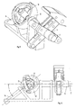
Fig.1 : First crank (1) joined to the first axis (2), second crank (3) joined to the second axis (4) concentric with the first axis and the connecting rod (6). -
Fig.2 : Links shown inFig.1 properly assembled. Base plate (7) upon which the stator will be fixed. -
Fig.3 : Piston (5) whose pivoting and centers of curvature of the ends are aligned and whose centers of curvature are 2 m apart with an arm length of the first crank m. Connecting rod (6) that joins the second crank to the piston. The assembly of piston, connecting rod, second crank and first crank form a deformable rhombusFig. (3 ). -
Fig.4 : Oval rotating levers, two of which are located on the concentric axes (2) and (4) of each crank and the other two, joined together (9) pivoting on an axis (10) -
Fig.5 : Double-cardan joint connecting the first (2) and second (4) coaxial axes with a third axis (14) being "v" the angle of deviation of the latter with respect to the coaxial axes. -
Fig.6 : Elements ofFig.5 and position of angle "v". -
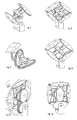
Fig.7 : Drawing of the application referred to. For the stator the particularized coefficient g has been used with a value g = 0,25 -
Fig.8 : View of the elements inFig.7 where one can see the two pairs of gears interlocking. -
Fig.9 : Assembly with two pistons. -
Fig.10 : Assembly with four pistons. -
Fig.11 : Assembly in which the first crank transmits, via two cardan joints arranged in series and 90° off-set, the movement of a conical gear that interlocks with another one joined to the second crank. -
Fig.12 : Assembly with four pistons where the pistons themselves play the role of the connecting rods. -
Fig.13 : Possibility of simultaneously using in parallel oval levers and oval indented gears. -
Fig.14 : Variant ofFig.4 where only two rotating levers are used and two gears. The lower rotation lever is joined to the lower gear. - Main double crank (1) joined by a main axis (2)
Fig.1 and Fig.3 , - Secondary double crank (3) joined by a secondary axis (4) concentric to the main axis
Fig.1 and Fig.2 . - Pistons (5)
Fig.2 whose articulation and centers of curvature of their ends are aligned and whose centers are 2 "m" apart being "m" the measurement of the crank upon whichFig.3 pivots. - Connecting rods (6) that join the secondary crank to the piston
Fig.1 . The assembly of piston, connecting rod, secondary crank and main crank form a deformable rhombusFig.(3 ). - Base plate (7)
Fig.3 to which the stator and axes pivots are fixed. - An oval stator
Fig.7 and 8 designed in such a way that the segments of the piston follow its contour. Oval rotating levers, two of which are located on the concentric axes (2) and (4) of each crank and the other two joined to each other (8). - Four oval rotating levers, two of which are located on the concentric axes (2) and (4) of each crank and the other two, joined to each other (8)
Fig.4 , pivot on an axis positioned at a distance "d" (9)Fig.3 from the crank axes. - Assembly
Fig. 7 and Fig. 8 representing the stator, having chosen the value g = 0.25 for coefficient g.
Claims (13)
- Oscillating-piston guide system for compressors and rotary engines that are made up of pistons whose articulation and centers of curvature of their ends are aligned and whose centers of curvature are at a distance of twice the length of the arm of the first crank upon which they pivot (Fig.3), characterized by that fact that each piston (5) is joined via a connecting rod (6) to a second crank (3), coaxialar with the first crank (1), with these four bodies forming a deformable rhombus, enabling the piston and the second crank to remain always parallel, with the motion of the two cranks being synchronized on being connected by an external mechanism which ensures that the whole assembly only has one degree of freedom and that the piston ends scribe the desired contour without the need to touch the stator.
- Oscillating-piston guide system for compressors and rotary engines according to Claim 1 characterized because the motion ratio between the two cranks is defined because the angle "b" which turns the secondary crank is defined by the angle "a" which turns the primary crank as the aforementioned cranks are connected via a mechanism that produces this ratio:


- Oscillating-piston guide system for compressors and rotary engines according to claim 1 and 2 characterized because the relationship between the movement between the two cranks is achieved by 4 rolling oval levers, (Fig.4), two of which are positioned on the concentric axes of each crank and the other two, joined together and off-set at 90°, pivoting on a parallel axis located at a distance "d" from the axes of the cranks, the contour of the oval crank levers fulfilling the equation in polar definition with the radius r in terms of the angle e :

- Oscillating-piston guide system for compressors and rotary engines according to claim 1 and 2 characterized by the fact that the relationship of the motion between the two cranks is achieved by 4 rolling oval levers, two of which are located on the concentric axes of each crank and the other two, joined together and off-set 90°, turning upon a parallel axis and the latter having a perimeter half that of the former ones scribing the contours in such a way that the oval crank levers are in constant contact two by two and pivoting without slipping produce the motion ratio:

- Oscillating-piston guide system for compressors and rotary engines according to claim 1 and 2 characterized because the motion ration of the two cranks is achieved by 2 rolling oval levers, (Fig.14), one of which is located on the concentric axis of the first crank and the other, rotating with the first, turning upon a parallel axis located at a distance "d" from the axes of the cranks, with the latter being joined to a gear that interlocks with another of the same size joined to the axis of the second crank, the contour of the oval crank levers fulfilling the equation defined in polar definition with radius r in terms of the angle e :

- Oscillating-piston guide system for compressors and rotary engines according to claim 3 or 4 characterized in that the rolling oval levers are constructed with teeth so that they interlock with each other, the rolling circle being the previously mentioned contours and maintaining either part or none of the untoothed thickness (Fig.13).
- Oscillating-piston guide system for compressors and rotary engines according to claims 1 and 2 characterized by the fact that the motion ration between the two cranks is achieved by a third axis joined to a double-cardan joint (Fig.5) and (Fig.6) that consistes of two jaws off-set 90° one of which is used to connect, via a sprocket, the axis of the first crank and using the other to connect, via an exterior ring of hollow component, the axis of the second crank, being v the deviation angle of the third axis with respect to the coaxial axes, fulfilling:

- Oscillating-piston guide system for compressors and rotary engines according to claim 1 and 2 characterized by the fact that the motion ratio between the two cranks is achieved via a cardan joint (Fig.11) which connects the coaxial axis of a crank to an axis whose angle of deviation compared to the former is "v" and that is, in turn, connected by a second joint, off-set 90° with respect to the first, with another axis also deviating at an angle "v" and joined to the axis of the other crank via conical gears with the same number of teeth, with v equal to a :

- Oscillating-piston guide system for compressors and rotary engines according to claim 1 and 2 characterized in that the motion ratio between the two cranks is achieved via a simple cardan joint connecting the coaxial axis of one crank with an axis whose angle of deviation with respect to the former is "v" and that is connected to the axis of the other crank via conical gears with the same number of teeth, being v equal to a:

- Oscillating-piston guide system for compressors and rotary engines according to the previous claims characterized in that it is made with two pistons arranged diametrally (Fig.9), that turn on the ends of one sole first diametral crank and that are connected to a second crank by means of two connecting rods.
- Oscillating-piston guide system for compressors and rotary engines according to claim 9 characterized in that is made with two pistons that turn on the ends of a first double crank and another two pistons (Fig.10) that turn on the ends of the second double crank of the same size as the principal crank with the four pistons connected via connecting rods with the cranks parallel to each other.
- Oscillating-piston guide system for compressors and rotary engines according to claim 10 characterized in that it uses pistons, that are connected to each other, as connecting rods to form a deformable rhombus (Fig.12) and achieve that two piston are parallel to the first crank and the other two are parallel to the second crank.
- Oscillating-piston guide system for compressors and rotary engines according to claim 1 characterized in that the motion ration between the two cranks is achieved via 4 non-circular rotating levers, two of which are placed on the concentric axes of each crank and the other two, joined together, rotate on a parallel axis located at a distance "d" from the axes of the cranks, scribing the contour of the levers such that piston ends scribe any contour of the stator that is desired.
Applications Claiming Priority (2)
| Application Number | Priority Date | Filing Date | Title |
|---|---|---|---|
| ES200600383A ES2285930B1 (en) | 2006-02-17 | 2006-02-17 | GUIDING SYSTEM FOR COMBINING OR ROTATING ENGINES OR ROTATING ENGINES. |
| PCT/ES2007/000010 WO2007093649A1 (en) | 2006-02-17 | 2007-01-11 | Guide system for the oscillating pistons of rotary motors or compressors |
Publications (3)
| Publication Number | Publication Date |
|---|---|
| EP2003288A2 true EP2003288A2 (en) | 2008-12-17 |
| EP2003288A9 EP2003288A9 (en) | 2009-04-15 |
| EP2003288A4 EP2003288A4 (en) | 2015-07-29 |
Family
ID=38371204
Family Applications (1)
| Application Number | Title | Priority Date | Filing Date |
|---|---|---|---|
| EP07704724.9A Withdrawn EP2003288A4 (en) | 2006-02-17 | 2007-01-11 | Guide system for the oscillating pistons of rotary motors or compressors |
Country Status (3)
| Country | Link |
|---|---|
| EP (1) | EP2003288A4 (en) |
| ES (1) | ES2285930B1 (en) |
| WO (1) | WO2007093649A1 (en) |
Families Citing this family (2)
| Publication number | Priority date | Publication date | Assignee | Title |
|---|---|---|---|---|
| FR2938291B1 (en) | 2008-11-12 | 2010-11-12 | Vincent Genissieux | DEFORMABLE LODGE ROTATING MACHINE COMPRISING AN IMPROVED TRANSMISSION MECHANISM. |
| US20150275748A1 (en) * | 2014-03-31 | 2015-10-01 | Gene Underwood | Rotary Compression Engine |
Family Cites Families (8)
| Publication number | Priority date | Publication date | Assignee | Title |
|---|---|---|---|---|
| US716970A (en) * | 1902-05-26 | 1902-12-30 | Edward H Werner | Rotary engine. |
| DE1551115A1 (en) * | 1966-09-29 | 1970-06-11 | Alfred Jordan | Rotary piston internal combustion engine, in particular air-cooled rotary piston engine for the gas-air mixture or air-cooled rotary piston diesel engine |
| US3769946A (en) * | 1969-07-14 | 1973-11-06 | W Scherrer | Rotary engines |
| ES416371A1 (en) * | 1973-06-27 | 1976-05-16 | Martin Artajo | Machine with rotary articulated pistons |
| DE2656751A1 (en) * | 1976-12-15 | 1978-06-22 | Alfred Jordan | ROTATIONAL PISTON ENGINE IN PARTICULAR FOR FUEL-AIR MIXTURE OR DIESEL OIL INJECTION |
| EP0160040A1 (en) * | 1983-10-13 | 1985-11-06 | Hubert Petutschnig | Rotary motor, rotary compressor |
| US7178502B2 (en) * | 2001-06-05 | 2007-02-20 | Paul D. Okulov | Balanced rotary internal combustion engine or cycling volume machine |
| US6899075B2 (en) * | 2002-03-22 | 2005-05-31 | Roxan Saint-Hilaire | Quasiturbine (Qurbine) rotor with central annular support and ventilation |
-
2006
- 2006-02-17 ES ES200600383A patent/ES2285930B1/en not_active Withdrawn - After Issue
-
2007
- 2007-01-11 WO PCT/ES2007/000010 patent/WO2007093649A1/en active Application Filing
- 2007-01-11 EP EP07704724.9A patent/EP2003288A4/en not_active Withdrawn
Non-Patent Citations (1)
| Title |
|---|
| See references of WO2007093649A1 * |
Also Published As
| Publication number | Publication date |
|---|---|
| WO2007093649A1 (en) | 2007-08-23 |
| ES2285930A1 (en) | 2007-11-16 |
| ES2285930B1 (en) | 2008-10-16 |
| EP2003288A9 (en) | 2009-04-15 |
| EP2003288A4 (en) | 2015-07-29 |
Similar Documents
| Publication | Publication Date | Title |
|---|---|---|
| EP2233691B1 (en) | Volume expansion rotary piston machine | |
| US5673665A (en) | Engine with rack gear-type piston rod | |
| US7255086B2 (en) | Rotary internal combustion engine | |
| EP2066889B1 (en) | Improved opposed piston combustion engine | |
| US20100000492A1 (en) | Modified revolving piston internal combustion engine | |
| US4010716A (en) | Rotary engine | |
| CN102191996A (en) | Split-cycle internal combustion engine | |
| US20080159897A1 (en) | Reciprocating Component-Free Kinematic Motion Apparatus for Transforming Pressure Variations of a Fluid Operating in Cyclically Variable Volume Toroidal Chambers into a Mechanical Work on a Rotary Axis and Engine Including Said Apparatus | |
| US5359908A (en) | System for reversibly transforming rotary motion into self-guided rectilinear motion | |
| EP2003288A2 (en) | Guide system for the oscillating pistons of rotary motors or compressors | |
| US5212996A (en) | Crank drive with planetary pivot pin, favourably for piston power engines and machine tools | |
| US8408179B2 (en) | Rotary piston combustion engine | |
| US20060150947A1 (en) | Revolving piston internal combustion engine | |
| US7926462B2 (en) | Kinetic energy generation device | |
| US3304923A (en) | Engine | |
| RU2496998C2 (en) | Rotary-vane ice | |
| GB2516411A (en) | Opposed stepped piston engine with eccentric rod drives and power take-offs | |
| RU2405939C2 (en) | Hinged-piston mechanism | |
| WO2015159083A1 (en) | Opposed piston machine with rectilinear drive mechanisms | |
| US4173439A (en) | Apparatus having expanding and contracting chamber | |
| WO2013013250A2 (en) | Volumetric rotary machine (variants) | |
| US7284513B2 (en) | Internal combustion engine without connecting rod and a method of its construction | |
| US4517932A (en) | Paired beam engines and pumps | |
| US4651685A (en) | Paired beam engines and pumps | |
| RU2348822C2 (en) | Crankshaft-rocker-coupler mechanism |
Legal Events
| Date | Code | Title | Description |
|---|---|---|---|
| PUAI | Public reference made under article 153(3) epc to a published international application that has entered the european phase |
Free format text: ORIGINAL CODE: 0009012 |
|
| 17P | Request for examination filed |
Effective date: 20080805 |
|
| AK | Designated contracting states |
Kind code of ref document: A2 Designated state(s): AT BE BG CH CY CZ DE DK EE ES FI FR GB GR HU IE IS IT LI LT LU LV MC NL PL PT RO SE SI SK TR |
|
| PUAB | Information related to the publication of an a document modified or deleted |
Free format text: ORIGINAL CODE: 0009199EPPU |
|
| DAX | Request for extension of the european patent (deleted) | ||
| RA4 | Supplementary search report drawn up and despatched (corrected) |
Effective date: 20150701 |
|
| RIC1 | Information provided on ipc code assigned before grant |
Ipc: F01C 1/44 20060101AFI20150625BHEP |
|
| STAA | Information on the status of an ep patent application or granted ep patent |
Free format text: STATUS: THE APPLICATION IS DEEMED TO BE WITHDRAWN |
|
| 18D | Application deemed to be withdrawn |
Effective date: 20160128 |