EP2003285B1 - Umbilical deployment system - Google Patents
Umbilical deployment system Download PDFInfo
- Publication number
- EP2003285B1 EP2003285B1 EP08154996A EP08154996A EP2003285B1 EP 2003285 B1 EP2003285 B1 EP 2003285B1 EP 08154996 A EP08154996 A EP 08154996A EP 08154996 A EP08154996 A EP 08154996A EP 2003285 B1 EP2003285 B1 EP 2003285B1
- Authority
- EP
- European Patent Office
- Prior art keywords
- umbilical
- water
- deployment
- bed
- parking unit
- Prior art date
- Legal status (The legal status is an assumption and is not a legal conclusion. Google has not performed a legal analysis and makes no representation as to the accuracy of the status listed.)
- Not-in-force
Links
- 238000009434 installation Methods 0.000 claims description 16
- XLYOFNOQVPJJNP-UHFFFAOYSA-N water Substances O XLYOFNOQVPJJNP-UHFFFAOYSA-N 0.000 claims description 14
- 238000000034 method Methods 0.000 claims description 12
- 238000012544 monitoring process Methods 0.000 claims description 6
- 230000000717 retained effect Effects 0.000 claims description 6
- 238000009826 distribution Methods 0.000 claims description 5
- 230000014759 maintenance of location Effects 0.000 claims 1
- 230000002829 reductive effect Effects 0.000 description 5
- 238000004519 manufacturing process Methods 0.000 description 3
- 238000003860 storage Methods 0.000 description 3
- 239000004215 Carbon black (E152) Substances 0.000 description 2
- 230000000694 effects Effects 0.000 description 2
- 239000012530 fluid Substances 0.000 description 2
- 229930195733 hydrocarbon Natural products 0.000 description 2
- 150000002430 hydrocarbons Chemical class 0.000 description 2
- 230000033001 locomotion Effects 0.000 description 2
- 230000003287 optical effect Effects 0.000 description 2
- 230000003068 static effect Effects 0.000 description 2
- 230000006834 demobilisation Effects 0.000 description 1
- 238000000605 extraction Methods 0.000 description 1
- 230000000135 prohibitive effect Effects 0.000 description 1
- 230000000284 resting effect Effects 0.000 description 1
Images

Classifications
-
- E—FIXED CONSTRUCTIONS
- E21—EARTH OR ROCK DRILLING; MINING
- E21B—EARTH OR ROCK DRILLING; OBTAINING OIL, GAS, WATER, SOLUBLE OR MELTABLE MATERIALS OR A SLURRY OF MINERALS FROM WELLS
- E21B19/00—Handling rods, casings, tubes or the like outside the borehole, e.g. in the derrick; Apparatus for feeding the rods or cables
- E21B19/002—Handling rods, casings, tubes or the like outside the borehole, e.g. in the derrick; Apparatus for feeding the rods or cables specially adapted for underwater drilling
-
- E—FIXED CONSTRUCTIONS
- E21—EARTH OR ROCK DRILLING; MINING
- E21B—EARTH OR ROCK DRILLING; OBTAINING OIL, GAS, WATER, SOLUBLE OR MELTABLE MATERIALS OR A SLURRY OF MINERALS FROM WELLS
- E21B33/00—Sealing or packing boreholes or wells
- E21B33/02—Surface sealing or packing
- E21B33/03—Well heads; Setting-up thereof
- E21B33/035—Well heads; Setting-up thereof specially adapted for underwater installations
- E21B33/0355—Control systems, e.g. hydraulic, pneumatic, electric, acoustic, for submerged well heads
-
- E—FIXED CONSTRUCTIONS
- E21—EARTH OR ROCK DRILLING; MINING
- E21B—EARTH OR ROCK DRILLING; OBTAINING OIL, GAS, WATER, SOLUBLE OR MELTABLE MATERIALS OR A SLURRY OF MINERALS FROM WELLS
- E21B41/00—Equipment or details not covered by groups E21B15/00 - E21B40/00
- E21B41/0007—Equipment or details not covered by groups E21B15/00 - E21B40/00 for underwater installations
-
- E—FIXED CONSTRUCTIONS
- E21—EARTH OR ROCK DRILLING; MINING
- E21B—EARTH OR ROCK DRILLING; OBTAINING OIL, GAS, WATER, SOLUBLE OR MELTABLE MATERIALS OR A SLURRY OF MINERALS FROM WELLS
- E21B43/00—Methods or apparatus for obtaining oil, gas, water, soluble or meltable materials or a slurry of minerals from wells
- E21B43/01—Methods or apparatus for obtaining oil, gas, water, soluble or meltable materials or a slurry of minerals from wells specially adapted for obtaining from underwater installations
-
- F—MECHANICAL ENGINEERING; LIGHTING; HEATING; WEAPONS; BLASTING
- F16—ENGINEERING ELEMENTS AND UNITS; GENERAL MEASURES FOR PRODUCING AND MAINTAINING EFFECTIVE FUNCTIONING OF MACHINES OR INSTALLATIONS; THERMAL INSULATION IN GENERAL
- F16L—PIPES; JOINTS OR FITTINGS FOR PIPES; SUPPORTS FOR PIPES, CABLES OR PROTECTIVE TUBING; MEANS FOR THERMAL INSULATION IN GENERAL
- F16L11/00—Hoses, i.e. flexible pipes
- F16L11/04—Hoses, i.e. flexible pipes made of rubber or flexible plastics
- F16L11/12—Hoses, i.e. flexible pipes made of rubber or flexible plastics with arrangements for particular purposes, e.g. specially profiled, with protecting layer, heated, electrically conducting
Definitions
- This invention relates to a method for providing a back-up umbilical for a well installation, and a back-up umbilical deployment system for a well installation located at the bed of a body of water.
- the well installation may for example be a subsea hydrocarbon extraction well, although such installations may equally be located in bodies of water such as lakes.
- Control, monitoring and powering of a subsea hydrocarbon fluid production well for example is effected from a surface or land-based platform via an umbilical cable which carries the necessary electric / hydraulic power lines and electrical / optical communication lines.
- This umbilical is connected at its lower end to, typically, a subsea control and distribution unit (CDU), with the control signals / power being distributed to the various trees at the well heads on the sea bed as required.
- CDU subsea control and distribution unit
- BUIC Back-Up Intervention Control
- a BUIC system is effectively an insurance policy against failure of the prime controls umbilical, and is typically purchased where the prime umbilical is considered sufficiently vulnerable.
- a BUIC system is designed to be deployed only when a failure in the prime umbilical occurs, and a vessel is used for this deployment. Since the cost of maintaining a vessel to provide this service is prohibitive, most well operators opt for a BUIC system that employs a "vessel of opportunity" with limited facilities. While there is generally assistance from a Remotely Operated Vehicle (ROV) to enable disconnection of the umbilical and connection of the back-up umbilical at the CDU, there is generally no lift assistance available.
- ROV Remotely Operated Vehicle
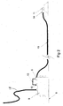
- FIG. 1 A typical deployment of a BUIC system is shown in Fig. 1 .
- a vessel for example a vessel of opportunity, carries a replacement dynamic umbilical 2 stowed on a reel / winch assembly 3.
- the assembly 3 is integrated with a handling / overboarding mechanism used to deploy the umbilical 2.
- EQDP Emergency Quick Disconnect Package
- EQDP Emergency Quick Disconnect Package
- the umbilical 2 may include buoyancy devices 5 to support the umbilical within the water.
- the umbilical 2, and umbilical-mounted half of the EQDP 4 are typically stowed on the reel 3 for handling through the handling / overboarding mechanism.
- the buoyancy devices 5 may also be stowed on the reel 3 if the operator requests this facility, alternatively they may be attached to the umbilical on installation.
- the lower end of the umbilical is connected to a subsea umbilical termination (SUT) 6. This provides connection with a CDU 8 via CDU receptacle 7.
- SUT subsea umbilical termination
- the umbilical 2 To deploy the umbilical 2, it is unwound from the reel 3, through the handling / overboard mechanism and over the side of the vessel 1.
- the umbilical 2 is required to support its own weight, plus that of the SUT 6, through the water column under the prevailing weather, sea and current conditions.
- the umbilical 2 and its termination 6 For connection with the well installation, the umbilical 2 and its termination 6 must be presented directly above and correctly oriented to the receptacle 7. This is often possible in light weather and sea conditions, but is unlikely to be successful in any other sea state, and is a difficult and thus expensive exercise.
- the vessel of opportunity is unlikely to be as stable a platform as a larger installation vessel, and will therefore have greater pitch, heave and roll motions for any given set of weather or sea conditions.
- Such a vessel does not generally have a moonpool facility, which means that overboarding of the umbilical, in the worst case scenario, has to be over the stem of the vessel. This is probably the worst location at which to overboard a dynamic umbilical when trying to position the SUT at installation.
- US-A-6 102 124 discloses a system in which, for workover, a hydraulic umbilical remains connected to a control pod at a well tree and an electrical umbilical from a workover vessel is connected to the control pod.
- a system and method in accordance with the present invention confers many advantages, for example:
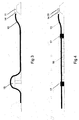
- a system in accordance with the present invention may be installed in a number of ways, depending on the results of a dynamic analysis of the umbilical and the recommendations as to its installed configuration, for example "Lazy Wave”, “Steep Wave” or simple catenary.
- Various installation possibilities are shown in Figs. 2 to 4 .
- FIG. 2 A comparatively simple system to install is shown in Fig. 2 , where a simple catenary is shown to be a viable solution.
- a back-up umbilical 10 is laid out on the seabed 9, which may be carried out at the same time as installation of main umbilical 18, so as to be retained in a static position.
- One end of the umbilical 10 finishes in a recoverable SUT 6, which is connected to CDU 8.
- the CDU 8 has BUIC ports 12 for hydraulic and / or electrical power and electrical and / or optical communications as required, the ports 12 being linked by jumpers 13 to the SUT 6.
- the other end of the umbilical 10 finishes in a connector 14, which forms half of an EQDP.
- Connector 14 is releasably connected to a parking unit 11. Parking unit 11 lies on the seabed due to the combined weight of the parking unit 11 and umbilical 10, resting on or in a predeployed storage base (not shown) and acts to protect the end of umbilical 10.
- an ROV (not shown) takes a lift line from a winch on a surface vessel or platform and attaches it to the connector 14 or parking unit 11. The winch then lifts the connector 14 end of the umbilical 10, together with the parking unit 11, up to the surface platform / vessel, where the umbilical 10 is connected to the BUIC system housed thereon.
- Fig. 3 shows part of an alternative arrangement, used for example where it is determined that a "Lazy Wave" configuration is required.
- deflection means 15 on the seaked 9 in this case a buoyant arch, is used to support a portion of the umbilical 10, to arrange it in a non-linear fashion and thus introduce slack into the umbilical, which decouples vessel motions (and therefore loads) from the SUT interface to the CDU.
- Fig. 4 shows part of an alternative arrangement, in which the umbilical 10 is provided with buoyancy modules 16 positioned as required along its length. These act to reduce the load weight on the EQDP under both static and dynamic heave conditions.
- the buoyancy modules 16 are held to the seabed by tethering to clump weights 17. Weights 17 are detachable from the umbilical 10 by an ROV.
- the buoyancy means shown in Fig. 4 may be used in conjunction with the deflection means of Fig. 3 .
- Confidence in the health of the umbilical can be achieved by incorporating a cross connection system in the parking unit, allowing electrical power and fibre-optic communications to be looped between the multiple paths normally incorporated in the umbilical for monitoring purposes.
Landscapes
- Engineering & Computer Science (AREA)
- Geology (AREA)
- Life Sciences & Earth Sciences (AREA)
- Mining & Mineral Resources (AREA)
- Environmental & Geological Engineering (AREA)
- Fluid Mechanics (AREA)
- Physics & Mathematics (AREA)
- General Life Sciences & Earth Sciences (AREA)
- Geochemistry & Mineralogy (AREA)
- Mechanical Engineering (AREA)
- General Engineering & Computer Science (AREA)
- Other Liquid Machine Or Engine Such As Wave Power Use (AREA)
- Farming Of Fish And Shellfish (AREA)
Description
- This invention relates to a method for providing a back-up umbilical for a well installation, and a back-up umbilical deployment system for a well installation located at the bed of a body of water. The well installation may for example be a subsea hydrocarbon extraction well, although such installations may equally be located in bodies of water such as lakes.
- Control, monitoring and powering of a subsea hydrocarbon fluid production well for example is effected from a surface or land-based platform via an umbilical cable which carries the necessary electric / hydraulic power lines and electrical / optical communication lines. This umbilical is connected at its lower end to, typically, a subsea control and distribution unit (CDU), with the control signals / power being distributed to the various trees at the well heads on the sea bed as required. In the event of a failure of the umbilical a Back-Up Intervention Control (BUIC) system may be employed to replace the services normally provided by the umbilical in order to continue fluid production from the well until the umbilical is repaired. A BUIC system is effectively an insurance policy against failure of the prime controls umbilical, and is typically purchased where the prime umbilical is considered sufficiently vulnerable. A BUIC system is designed to be deployed only when a failure in the prime umbilical occurs, and a vessel is used for this deployment. Since the cost of maintaining a vessel to provide this service is prohibitive, most well operators opt for a BUIC system that employs a "vessel of opportunity" with limited facilities. While there is generally assistance from a Remotely Operated Vehicle (ROV) to enable disconnection of the umbilical and connection of the back-up umbilical at the CDU, there is generally no lift assistance available.
- A typical deployment of a BUIC system is shown in
Fig. 1 . A vessel 1, for example a vessel of opportunity, carries a replacement dynamic umbilical 2 stowed on a reel / winch assembly 3. The assembly 3 is integrated with a handling / overboarding mechanism used to deploy the umbilical 2. Integrated into this system is an Emergency Quick Disconnect Package (EQDP) 4 which permits simple disconnection of the umbilical 2. - Furthermore, the umbilical 2 may include
buoyancy devices 5 to support the umbilical within the water. The umbilical 2, and umbilical-mounted half of the EQDP 4, are typically stowed on the reel 3 for handling through the handling / overboarding mechanism. Thebuoyancy devices 5 may also be stowed on the reel 3 if the operator requests this facility, alternatively they may be attached to the umbilical on installation. The lower end of the umbilical is connected to a subsea umbilical termination (SUT) 6. This provides connection with a CDU 8 via CDUreceptacle 7. - To deploy the umbilical 2, it is unwound from the reel 3, through the handling / overboard mechanism and over the side of the vessel 1. The umbilical 2 is required to support its own weight, plus that of the SUT 6, through the water column under the prevailing weather, sea and current conditions. For connection with the well installation, the
umbilical 2 and itstermination 6 must be presented directly above and correctly oriented to thereceptacle 7. This is often possible in light weather and sea conditions, but is unlikely to be successful in any other sea state, and is a difficult and thus expensive exercise. The vessel of opportunity is unlikely to be as stable a platform as a larger installation vessel, and will therefore have greater pitch, heave and roll motions for any given set of weather or sea conditions. Such a vessel does not generally have a moonpool facility, which means that overboarding of the umbilical, in the worst case scenario, has to be over the stem of the vessel. This is probably the worst location at which to overboard a dynamic umbilical when trying to position the SUT at installation. -
US-A-6 102 124 discloses a system in which, for workover, a hydraulic umbilical remains connected to a control pod at a well tree and an electrical umbilical from a workover vessel is connected to the control pod.. - It is an aim of the present invention to provide a method and system for deploying a back-up umbilical so as to enable a "predeployed" umbilical, which may be installed at the same time as the main production umbilical and is retained within the body of water during the normal operation of the well, so that its operative connection may be effected quickly and easily, without depending on accurate vessel positioning. Potentially, a smaller vessel may also be used to effect connection.
- With such a system, instead of requiring full installation of the umbilical, one end of the umbilical is recovered and lifted up to a connection system on the vessel.
- A system and method in accordance with the present invention confers many advantages, for example:
- no lift assistance is necessary;
- very accurate vessel manoeuvring is not required;
- manpower requirements are reduced;
- weather and sea state conditions are of less influence, this leads in turn to a potentially wider weather / sea state intervention window;
- the mechanical systems within the BUIC system are simplified, as there is no requirement for umbilical stowage on a reel or an overboarding / handling mechanism and only a winch is required;
- reduced mechanical risk to the umbilical and SUT during an intervention;
- the EQDP does not have to be stowed on a reel or handled through an overboarding / handling mechanism;
- reduced size and weight of ship-borne BUICS equipment;
- no buoyancy handling or attachment issues on the vessel. Buoyancy does not have to withstand stowage crushing forces on a reel or winch;
- reduced crane lift capability at mobilisation and demobilisation;
- reduced onshore storage provision as neither an umbilical nor storage reel need be kept onshore;
- greater potential to automate or semi-automate ship-borne mechanical BUICS functions; and
- quicker mobilisation of dockside-stored BUICS equipment.
- The present invention is defined by the accompanying claims.
- The invention will now be described, by way of example, with reference to the accompanying drawings, in which:-
-
Fig. 1 shows a conventional umbilical deployment technique; -
Fig. 2 shows a first embodiment of a pre-deployed umbilical system in accordance with the present invention; -
Fig. 3 shows a second embodiment of a system in accordance with the present invention; and -
Fig. 4 shows a third embodiment of a system in accordance with the present invention. - A system in accordance with the present invention may be installed in a number of ways, depending on the results of a dynamic analysis of the umbilical and the recommendations as to its installed configuration, for example "Lazy Wave", "Steep Wave" or simple catenary. Various installation possibilities are shown in
Figs. 2 to 4 . - A comparatively simple system to install is shown in
Fig. 2 , where a simple catenary is shown to be a viable solution. A back-up umbilical 10 is laid out on theseabed 9, which may be carried out at the same time as installation of main umbilical 18, so as to be retained in a static position. One end of the umbilical 10 finishes in a recoverable SUT 6, which is connected to CDU 8. The CDU 8 hasBUIC ports 12 for hydraulic and / or electrical power and electrical and / or optical communications as required, theports 12 being linked byjumpers 13 to the SUT 6. The other end of the umbilical 10 finishes in aconnector 14, which forms half of an EQDP.Connector 14 is releasably connected to aparking unit 11.Parking unit 11 lies on the seabed due to the combined weight of theparking unit 11 and umbilical 10, resting on or in a predeployed storage base (not shown) and acts to protect the end of umbilical 10. - To effect operative deployment of the umbilical 10, an ROV (not shown) takes a lift line from a winch on a surface vessel or platform and attaches it to the
connector 14 orparking unit 11. The winch then lifts theconnector 14 end of the umbilical 10, together with theparking unit 11, up to the surface platform / vessel, where the umbilical 10 is connected to the BUIC system housed thereon. -
Fig. 3 shows part of an alternative arrangement, used for example where it is determined that a "Lazy Wave" configuration is required. In this embodiment, deflection means 15 on the seaked 9, in this case a buoyant arch, is used to support a portion of the umbilical 10, to arrange it in a non-linear fashion and thus introduce slack into the umbilical, which decouples vessel motions (and therefore loads) from the SUT interface to the CDU. -
Fig. 4 shows part of an alternative arrangement, in which the umbilical 10 is provided withbuoyancy modules 16 positioned as required along its length. These act to reduce the load weight on the EQDP under both static and dynamic heave conditions. Thebuoyancy modules 16 are held to the seabed by tethering to clumpweights 17.Weights 17 are detachable from the umbilical 10 by an ROV. - The above-described embodiments are exemplary only, and various possibilities are possible within the scope of the claims.
- The buoyancy means shown in
Fig. 4 may be used in conjunction with the deflection means ofFig. 3 . - Confidence in the health of the umbilical can be achieved by incorporating a cross connection system in the parking unit, allowing electrical power and fibre-optic communications to be looped between the multiple paths normally incorporated in the umbilical for monitoring purposes.
Claims (17)
- A method for providing a back-up umbilical connection for a well installation, the well installation being located at the bed (9) of a body of water, comprising the steps of:a) providing a back-up umbilical (10) having first and second ends with the first end being connected to a control and distribution unit (8) of the installation, a main umbilical (18) also being connected to the control and distribution unit;b) prior to operative deployment of the back-up umbilical, locating the back-up umbilical such that at least a portion of the back-up umbilical is statically retained within the body of water;c) providing a parking unit (11) on the bed of the body of water; andd) connecting the second end of the back-up umbilical to the parking unit.
- A method according to claim 1, wherein in step b), the portion of the back-up umbilical is retained proximate the bed (9) of the body of water.
- A method according to claim 1 or 2, comprising the step of:e) lifting the second end of the back-up umbilical (10) to a platform at the surface of the body of water.
- A method according to claim 3, wherein step e) is carried out using a remotely operated vehicle.
- A method according to any preceding claim, wherein the back-up umbilical (10) is provided with buoyancy means (16).
- A method according to any preceding claim, comprising the step of providing deflection means (15) to cause the back-up umbilical (10) to be non-linearly arranged during retention.
- A method according to any preceding claim, comprising the step of monitoring the health of the back-up umbilical (10) during detention.
- A method according to claim 7, wherein monitoring is carried out by passing signals through the back-up umbilical (10) via the parking unit (11).
- An umbilical deployment system for a well installation located at the bed (9) of a body of water, comprising a back-up umbilical (10) having first and second ends with the first end being connected to a control and distribution unit (8) of the installation, a main umbilical (18) also being connected to the control and distribution unit, wherein, prior to operative deployment of the back-up umbilical, at least a portion of the back-up umbilical is statically retained within the body of water, the system further comprising a parking unit (11) and the second end of the back-up umbilical (10) being connected to the parking unit prior to operative deployment
- A system according to claim 9, wherein prior to operative deployment, the portion of the back-up umbilical (10) is retained proximate the bed (9) of the body of water.
- A system according to claim 9 or 10, wherein the second end of the back-up umbilical (10) is releasably connected to the parking unit (11).
- A system according to any of claims 9 to 11, comprising deflection means (15) to retain the back-up umbilical (10) in a non-linear configuration prior to deployment.
- A system according to claim 12, wherein the deflection means (15) is on the bed (9) of the body of water.
- A system according to claim 12 or 13, wherein the deflection means (15) comprises a support for raising a portion of the back-up umbilical (10).
- A system according to any of claims 9 to 14, wherein the back-up umbilical (10) is provided with buoyancy means (16).
- A system according to any of claims 9 to 15, comprising means for monitoring the health of the back-up umbilical (10) prior to deployment.
- A system according to claim 16, wherein the monitoring means comprises means for passing signals through the back-up umbilical (10) via the parking unit (11).
Applications Claiming Priority (1)
| Application Number | Priority Date | Filing Date | Title |
|---|---|---|---|
| GB0711569A GB2450149A (en) | 2007-06-15 | 2007-06-15 | A backup umbilical connection for a well installation |
Publications (2)
| Publication Number | Publication Date |
|---|---|
| EP2003285A1 EP2003285A1 (en) | 2008-12-17 |
| EP2003285B1 true EP2003285B1 (en) | 2011-03-23 |
Family
ID=38332142
Family Applications (1)
| Application Number | Title | Priority Date | Filing Date |
|---|---|---|---|
| EP08154996A Not-in-force EP2003285B1 (en) | 2007-06-15 | 2008-04-23 | Umbilical deployment system |
Country Status (6)
| Country | Link |
|---|---|
| US (1) | US8096364B2 (en) |
| EP (1) | EP2003285B1 (en) |
| AU (1) | AU2008202637A1 (en) |
| BR (1) | BRPI0803714A2 (en) |
| DE (1) | DE602008005670D1 (en) |
| GB (1) | GB2450149A (en) |
Families Citing this family (8)
| Publication number | Priority date | Publication date | Assignee | Title |
|---|---|---|---|---|
| GB2478077B (en) * | 2008-02-26 | 2012-02-29 | Zetechtics Ltd | Subsea test apparatus, assembly and method |
| GB2474211B (en) * | 2008-08-13 | 2012-05-02 | Schlumberger Holdings | Umbilical management system and method for subsea well intervention |
| US8281862B2 (en) * | 2010-04-16 | 2012-10-09 | Halliburton Energy Services Inc. | Testing subsea umbilicals |
| US9038726B2 (en) * | 2012-06-12 | 2015-05-26 | Vetco Gray U.K., Limited | Light well intervention umbilical and flying lead management system and related methods |
| CN103883589B (en) * | 2014-03-20 | 2016-08-17 | 中国海洋石油总公司 | The most electro-hydraulic distributor |
| US9784074B1 (en) * | 2016-09-29 | 2017-10-10 | Onesubsea Ip Uk Limited | Extender jumper system and method |
| IT202100016124A1 (en) * | 2021-06-21 | 2022-12-21 | Saipem Spa | INSTALLATION AND METHOD OF INSTALLING DATA AND ELECTRICAL TRANSMISSION LINES ON A STEEL LAZY WAVE RISER (SLWR) |
| CN117328524A (en) * | 2023-11-28 | 2024-01-02 | 湖南千智机器人科技发展有限公司 | Marine engineering tunnel marine organism cleaning method and cleaning system |
Family Cites Families (26)
| Publication number | Priority date | Publication date | Assignee | Title |
|---|---|---|---|---|
| US4650431A (en) * | 1979-03-28 | 1987-03-17 | Amtel, Inc | Quick disconnect storage production terminal |
| EP0251488B1 (en) * | 1986-06-05 | 1991-11-06 | Bechtel Limited | Flexible riser system and method for installing the same |
| US4682913A (en) * | 1986-08-28 | 1987-07-28 | Shell Offshore Inc. | Hydraulic stab connector |
| GB8905364D0 (en) * | 1989-03-09 | 1989-04-19 | Britoil Plc | Offshore oil production system |
| BR9005129A (en) * | 1990-10-12 | 1992-06-30 | Petroleo Brasileiro Sa | SUBMARINE PRODUCTION SYSTEM AND LINES CONNECTION METHOD BETWEEN A MANIFOLD AND ADJACENT SATELLITE POCOS |
| FR2704250B1 (en) * | 1993-04-21 | 1995-06-30 | Coflexip | Method and device for continuously laying and burying a flexible underwater pipe. |
| US5505560A (en) * | 1993-10-26 | 1996-04-09 | Offshore Energie Development Corporation (Oecd) | Fluid transfer system for an offshore moored floating unit |
| US5582252A (en) * | 1994-01-31 | 1996-12-10 | Shell Oil Company | Hydrocarbon transport system |
| NO313500B1 (en) * | 1997-01-15 | 2002-10-14 | Abb Offshore Technology As | Buoyant body and method of using it |
| FR2766869B1 (en) * | 1997-08-01 | 1999-09-03 | Coflexip | DEVICE FOR TRANSFERRING FLUID BETWEEN A SUBSEA GROUND EQUIPMENT AND A SURFACE UNIT |
| AU746792B2 (en) | 1998-07-02 | 2002-05-02 | Fmc Technologies, Inc. | Flying lead workover interface system |
| US6223675B1 (en) * | 1999-09-20 | 2001-05-01 | Coflexip, S.A. | Underwater power and data relay |
| US8171989B2 (en) * | 2000-08-14 | 2012-05-08 | Schlumberger Technology Corporation | Well having a self-contained inter vention system |
| US6588980B2 (en) * | 2001-05-15 | 2003-07-08 | Halliburton Energy Services, Inc. | Underwater cable deployment system and method |
| US7032658B2 (en) * | 2002-01-31 | 2006-04-25 | Smart Drilling And Completion, Inc. | High power umbilicals for electric flowline immersion heating of produced hydrocarbons |
| US20030106714A1 (en) * | 2001-12-12 | 2003-06-12 | Smith Michael Lee | Use of coiled tubing unit systems in sub sea operations |
| US6742594B2 (en) * | 2002-02-06 | 2004-06-01 | Abb Vetco Gray Inc. | Flowline jumper for subsea well |
| NO328839B1 (en) * | 2002-02-28 | 2010-05-25 | Offshore Systems Inc | Method and apparatus for laying wires on the seabed |
| US7194913B2 (en) * | 2002-08-26 | 2007-03-27 | Shell Oil Company | Apparatuses and methods for monitoring stress in steel catenary risers |
| US6776559B1 (en) * | 2002-09-30 | 2004-08-17 | Gulf Fiber Corporation | Method and apparatus for deploying a communications cable below the surface of a body of water |
| US7031658B2 (en) * | 2003-03-07 | 2006-04-18 | Harris Corporation | System and method for single radio retransmission using a half duplex radio |
| GB2401164B (en) | 2003-04-29 | 2006-01-18 | Abb Offshore Systems Ltd | Pipeline protection system |
| US20050276665A1 (en) * | 2003-07-24 | 2005-12-15 | Entralgo Roger D | Remotely operated deployment system and method of use |
| GB2425565B (en) * | 2005-04-26 | 2009-05-20 | Vetco Gray Controls Ltd | Connection device |
| US20070044972A1 (en) * | 2005-09-01 | 2007-03-01 | Roveri Francisco E | Self-supported riser system and method of installing same |
| GB2440337B (en) * | 2006-01-21 | 2011-02-09 | Energy Equipment Corp | Method and apparatus for deploying a tubular |
-
2007
- 2007-06-15 GB GB0711569A patent/GB2450149A/en not_active Withdrawn
-
2008
- 2008-04-23 EP EP08154996A patent/EP2003285B1/en not_active Not-in-force
- 2008-04-23 DE DE602008005670T patent/DE602008005670D1/en active Active
- 2008-06-12 US US12/157,669 patent/US8096364B2/en not_active Expired - Fee Related
- 2008-06-13 AU AU2008202637A patent/AU2008202637A1/en not_active Abandoned
- 2008-06-16 BR BRPI0803714-0A patent/BRPI0803714A2/en not_active IP Right Cessation
Also Published As
| Publication number | Publication date |
|---|---|
| GB0711569D0 (en) | 2007-07-25 |
| US20080308277A1 (en) | 2008-12-18 |
| BRPI0803714A2 (en) | 2009-06-02 |
| US8096364B2 (en) | 2012-01-17 |
| DE602008005670D1 (en) | 2011-05-05 |
| GB2450149A (en) | 2008-12-17 |
| EP2003285A1 (en) | 2008-12-17 |
| AU2008202637A1 (en) | 2009-01-08 |
Similar Documents
| Publication | Publication Date | Title |
|---|---|---|
| EP2003285B1 (en) | Umbilical deployment system | |
| EP2859175B1 (en) | Light well intervention umbilical and flying lead management system and related methods | |
| EP1248723B1 (en) | Multi-rov delivery system and method | |
| RU2405711C1 (en) | Loading system | |
| US4547163A (en) | Oil transfer apparatus | |
| RU2672362C2 (en) | Mounting and dismounting of flexible line | |
| US8316947B2 (en) | System and method for deployment of a subsea well intervention system | |
| EP3350404B1 (en) | Subsea control pod deployment and retrieval systems and methods | |
| AU2014260519A2 (en) | Subsea remotely operated chain tensioning and slacking system | |
| US9976363B2 (en) | Offshore flexible line installation and removal | |
| JP4685525B2 (en) | Cable connecting device and underwater composite structure | |
| EP3008328A1 (en) | Power generating equipment | |
| EP1468215B1 (en) | Method of towing and installing a pipe | |
| WO1997025242A1 (en) | Spacing buoy for flexible risers | |
| AU2017320461B2 (en) | Umbilical method | |
| Sigrist et al. | Experience in float over integrated deck-flexibility of the concept | |
| CA3035716C (en) | Umbilical method | |
| HK40095170A (en) | Inter-array cable for floating platforms | |
| NO346089B1 (en) | Multi vessel method and system for placing an object on a seabed | |
| WO2018044174A1 (en) | Marine installation | |
| GB2463239A (en) | Subsea parking device |
Legal Events
| Date | Code | Title | Description |
|---|---|---|---|
| PUAI | Public reference made under article 153(3) epc to a published international application that has entered the european phase |
Free format text: ORIGINAL CODE: 0009012 |
|
| AK | Designated contracting states |
Kind code of ref document: A1 Designated state(s): AT BE BG CH CY CZ DE DK EE ES FI FR GB GR HR HU IE IS IT LI LT LU LV MC MT NL NO PL PT RO SE SI SK TR |
|
| AX | Request for extension of the european patent |
Extension state: AL BA MK RS |
|
| 17P | Request for examination filed |
Effective date: 20090423 |
|
| 17Q | First examination report despatched |
Effective date: 20090529 |
|
| AKX | Designation fees paid |
Designated state(s): DE FR GB NO |
|
| GRAJ | Information related to disapproval of communication of intention to grant by the applicant or resumption of examination proceedings by the epo deleted |
Free format text: ORIGINAL CODE: EPIDOSDIGR1 |
|
| GRAP | Despatch of communication of intention to grant a patent |
Free format text: ORIGINAL CODE: EPIDOSNIGR1 |
|
| GRAP | Despatch of communication of intention to grant a patent |
Free format text: ORIGINAL CODE: EPIDOSNIGR1 |
|
| GRAS | Grant fee paid |
Free format text: ORIGINAL CODE: EPIDOSNIGR3 |
|
| GRAA | (expected) grant |
Free format text: ORIGINAL CODE: 0009210 |
|
| AK | Designated contracting states |
Kind code of ref document: B1 Designated state(s): DE FR GB NO |
|
| REG | Reference to a national code |
Ref country code: GB Ref legal event code: FG4D |
|
| REF | Corresponds to: |
Ref document number: 602008005670 Country of ref document: DE Date of ref document: 20110505 Kind code of ref document: P |
|
| REG | Reference to a national code |
Ref country code: DE Ref legal event code: R096 Ref document number: 602008005670 Country of ref document: DE Effective date: 20110505 |
|
| REG | Reference to a national code |
Ref country code: NO Ref legal event code: T2 Effective date: 20110323 |
|
| PLBE | No opposition filed within time limit |
Free format text: ORIGINAL CODE: 0009261 |
|
| STAA | Information on the status of an ep patent application or granted ep patent |
Free format text: STATUS: NO OPPOSITION FILED WITHIN TIME LIMIT |
|
| 26N | No opposition filed |
Effective date: 20111227 |
|
| REG | Reference to a national code |
Ref country code: DE Ref legal event code: R097 Ref document number: 602008005670 Country of ref document: DE Effective date: 20111227 |
|
| PGFP | Annual fee paid to national office [announced via postgrant information from national office to epo] |
Ref country code: NO Payment date: 20130429 Year of fee payment: 6 Ref country code: DE Payment date: 20130429 Year of fee payment: 6 Ref country code: GB Payment date: 20130429 Year of fee payment: 6 |
|
| PGFP | Annual fee paid to national office [announced via postgrant information from national office to epo] |
Ref country code: FR Payment date: 20130506 Year of fee payment: 6 |
|
| REG | Reference to a national code |
Ref country code: DE Ref legal event code: R119 Ref document number: 602008005670 Country of ref document: DE |
|
| GBPC | Gb: european patent ceased through non-payment of renewal fee |
Effective date: 20140423 |
|
| REG | Reference to a national code |
Ref country code: DE Ref legal event code: R119 Ref document number: 602008005670 Country of ref document: DE Effective date: 20141101 |
|
| REG | Reference to a national code |
Ref country code: FR Ref legal event code: ST Effective date: 20141231 |
|
| PG25 | Lapsed in a contracting state [announced via postgrant information from national office to epo] |
Ref country code: NO Free format text: LAPSE BECAUSE OF NON-PAYMENT OF DUE FEES Effective date: 20140430 Ref country code: DE Free format text: LAPSE BECAUSE OF NON-PAYMENT OF DUE FEES Effective date: 20141101 Ref country code: GB Free format text: LAPSE BECAUSE OF NON-PAYMENT OF DUE FEES Effective date: 20140423 |
|
| PG25 | Lapsed in a contracting state [announced via postgrant information from national office to epo] |
Ref country code: FR Free format text: LAPSE BECAUSE OF NON-PAYMENT OF DUE FEES Effective date: 20140430 |