EP2003277A2 - Apparatus for controlling the movement of doors, gates and the like - Google Patents
Apparatus for controlling the movement of doors, gates and the like Download PDFInfo
- Publication number
- EP2003277A2 EP2003277A2 EP08102102A EP08102102A EP2003277A2 EP 2003277 A2 EP2003277 A2 EP 2003277A2 EP 08102102 A EP08102102 A EP 08102102A EP 08102102 A EP08102102 A EP 08102102A EP 2003277 A2 EP2003277 A2 EP 2003277A2
- Authority
- EP
- European Patent Office
- Prior art keywords
- leaf
- movement
- calculation module
- signal
- module
- Prior art date
- Legal status (The legal status is an assumption and is not a legal conclusion. Google has not performed a legal analysis and makes no representation as to the accuracy of the status listed.)
- Withdrawn
Links
Images

Classifications
-
- E—FIXED CONSTRUCTIONS
- E05—LOCKS; KEYS; WINDOW OR DOOR FITTINGS; SAFES
- E05F—DEVICES FOR MOVING WINGS INTO OPEN OR CLOSED POSITION; CHECKS FOR WINGS; WING FITTINGS NOT OTHERWISE PROVIDED FOR, CONCERNED WITH THE FUNCTIONING OF THE WING
- E05F15/00—Power-operated mechanisms for wings
- E05F15/40—Safety devices, e.g. detection of obstructions or end positions
- E05F15/42—Detection using safety edges
- E05F15/43—Detection using safety edges responsive to disruption of energy beams, e.g. light or sound
- E05F2015/434—Detection using safety edges responsive to disruption of energy beams, e.g. light or sound with cameras or optical sensors
- E05F2015/435—Detection using safety edges responsive to disruption of energy beams, e.g. light or sound with cameras or optical sensors by interruption of the beam
- E05F2015/436—Detection using safety edges responsive to disruption of energy beams, e.g. light or sound with cameras or optical sensors by interruption of the beam the beam being parallel to the wing edge
-
- E—FIXED CONSTRUCTIONS
- E05—LOCKS; KEYS; WINDOW OR DOOR FITTINGS; SAFES
- E05Y—INDEXING SCHEME ASSOCIATED WITH SUBCLASSES E05D AND E05F, RELATING TO CONSTRUCTION ELEMENTS, ELECTRIC CONTROL, POWER SUPPLY, POWER SIGNAL OR TRANSMISSION, USER INTERFACES, MOUNTING OR COUPLING, DETAILS, ACCESSORIES, AUXILIARY OPERATIONS NOT OTHERWISE PROVIDED FOR, APPLICATION THEREOF
- E05Y2400/00—Electronic control; Electrical power; Power supply; Power or signal transmission; User interfaces
- E05Y2400/10—Electronic control
- E05Y2400/36—Speed control, detection or monitoring
-
- E—FIXED CONSTRUCTIONS
- E05—LOCKS; KEYS; WINDOW OR DOOR FITTINGS; SAFES
- E05Y—INDEXING SCHEME ASSOCIATED WITH SUBCLASSES E05D AND E05F, RELATING TO CONSTRUCTION ELEMENTS, ELECTRIC CONTROL, POWER SUPPLY, POWER SIGNAL OR TRANSMISSION, USER INTERFACES, MOUNTING OR COUPLING, DETAILS, ACCESSORIES, AUXILIARY OPERATIONS NOT OTHERWISE PROVIDED FOR, APPLICATION THEREOF
- E05Y2400/00—Electronic control; Electrical power; Power supply; Power or signal transmission; User interfaces
- E05Y2400/10—Electronic control
- E05Y2400/45—Control modes
- E05Y2400/456—Control modes for programming, e.g. learning or AI [artificial intelligence]
-
- E—FIXED CONSTRUCTIONS
- E05—LOCKS; KEYS; WINDOW OR DOOR FITTINGS; SAFES
- E05Y—INDEXING SCHEME ASSOCIATED WITH SUBCLASSES E05D AND E05F, RELATING TO CONSTRUCTION ELEMENTS, ELECTRIC CONTROL, POWER SUPPLY, POWER SIGNAL OR TRANSMISSION, USER INTERFACES, MOUNTING OR COUPLING, DETAILS, ACCESSORIES, AUXILIARY OPERATIONS NOT OTHERWISE PROVIDED FOR, APPLICATION THEREOF
- E05Y2400/00—Electronic control; Electrical power; Power supply; Power or signal transmission; User interfaces
- E05Y2400/10—Electronic control
- E05Y2400/50—Fault detection
- E05Y2400/514—Fault detection of speed
-
- E—FIXED CONSTRUCTIONS
- E05—LOCKS; KEYS; WINDOW OR DOOR FITTINGS; SAFES
- E05Y—INDEXING SCHEME ASSOCIATED WITH SUBCLASSES E05D AND E05F, RELATING TO CONSTRUCTION ELEMENTS, ELECTRIC CONTROL, POWER SUPPLY, POWER SIGNAL OR TRANSMISSION, USER INTERFACES, MOUNTING OR COUPLING, DETAILS, ACCESSORIES, AUXILIARY OPERATIONS NOT OTHERWISE PROVIDED FOR, APPLICATION THEREOF
- E05Y2400/00—Electronic control; Electrical power; Power supply; Power or signal transmission; User interfaces
- E05Y2400/10—Electronic control
- E05Y2400/52—Safety arrangements associated with the wing motor
- E05Y2400/53—Wing impact prevention or reduction
-
- E—FIXED CONSTRUCTIONS
- E05—LOCKS; KEYS; WINDOW OR DOOR FITTINGS; SAFES
- E05Y—INDEXING SCHEME ASSOCIATED WITH SUBCLASSES E05D AND E05F, RELATING TO CONSTRUCTION ELEMENTS, ELECTRIC CONTROL, POWER SUPPLY, POWER SIGNAL OR TRANSMISSION, USER INTERFACES, MOUNTING OR COUPLING, DETAILS, ACCESSORIES, AUXILIARY OPERATIONS NOT OTHERWISE PROVIDED FOR, APPLICATION THEREOF
- E05Y2600/00—Mounting or coupling arrangements for elements provided for in this subclass
- E05Y2600/40—Mounting location; Visibility of the elements
- E05Y2600/45—Mounting location; Visibility of the elements in or on the fixed frame
-
- E—FIXED CONSTRUCTIONS
- E05—LOCKS; KEYS; WINDOW OR DOOR FITTINGS; SAFES
- E05Y—INDEXING SCHEME ASSOCIATED WITH SUBCLASSES E05D AND E05F, RELATING TO CONSTRUCTION ELEMENTS, ELECTRIC CONTROL, POWER SUPPLY, POWER SIGNAL OR TRANSMISSION, USER INTERFACES, MOUNTING OR COUPLING, DETAILS, ACCESSORIES, AUXILIARY OPERATIONS NOT OTHERWISE PROVIDED FOR, APPLICATION THEREOF
- E05Y2800/00—Details, accessories and auxiliary operations not otherwise provided for
- E05Y2800/15—Applicability
- E05Y2800/17—Universally applicable
- E05Y2800/176—Universally applicable on different wing types, weights or sizes
-
- E—FIXED CONSTRUCTIONS
- E05—LOCKS; KEYS; WINDOW OR DOOR FITTINGS; SAFES
- E05Y—INDEXING SCHEME ASSOCIATED WITH SUBCLASSES E05D AND E05F, RELATING TO CONSTRUCTION ELEMENTS, ELECTRIC CONTROL, POWER SUPPLY, POWER SIGNAL OR TRANSMISSION, USER INTERFACES, MOUNTING OR COUPLING, DETAILS, ACCESSORIES, AUXILIARY OPERATIONS NOT OTHERWISE PROVIDED FOR, APPLICATION THEREOF
- E05Y2900/00—Application of doors, windows, wings or fittings thereof
- E05Y2900/40—Application of doors, windows, wings or fittings thereof for gates
Definitions
- the present invention relates to an apparatus for controlling the movements of doors, gates, and the like.
- the invention in particular applies to the sector where doors and gates are moved in an automatic manner.
- a control unit carries out adjustment of operation of the movement member, both in terms of travel or movement stroke and in terms of speed.
- a solution that is typically utilised for observance of the rules and therefore for restricting damages in case of accidental impacts consists in use of pneumatic ribs mounted along the leaf profile; these pneumatic ribs are able to at least partly absorb, by deformation, the energy generated during the impact and can give rise to a notification signal directed to the control unit in order that movement of the door or gate be immediately stopped.
- the present invention aims at making available an apparatus for controlling the movement of doors, gates and the like that can be easily installed and has a structure of simple manufacture.
- the invention aims at making available an apparatus capable of defining the speed profiles for movement of the door leaf in a simple and reliable manner.
- Another aim of the invention is to provide an apparatus that can be easily adapted for correct operation even on leaves of sizes and weight different from each other.
- an apparatus for controlling the movement of doors, gates and the like in accordance with the present invention has been generally identified by reference numeral 1.
- Apparatus 1 can be applied to any type of automatic door or gate, in which at least one leaf is moved between a closed position and an open position.
- This leaf can be a sliding leaf, swing leaf or tilting leaf.
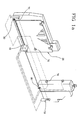
- Fig. 1a shows a gate with a sliding leaf
- Fig. 1b shows a gate with swing leaves.
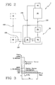
- Apparatus 1 first of all comprises a movement member 10 to move at least one leaf 20 of a door or gate.
- the movement member 10 can be a reduction motor, a direct or alternating current motor, a brush motor or an induction motor.
- the movement member 10 is adjusted through a high-frequency PWM (Pulse Width Modulation) control, so that the produced acoustic noise and disturbances in the supply mains are minimised.
- PWM Pulse Width Modulation
- the movement member 10 is interlocked with a control unit 30, operatively associated with the movement member for adjusting operation of same.
- the control unit 30 is provided with a reception module 31 for receiving a main signal 100 representative at least of the weight P of leaf 20; this information will be used, as better clarified in the following, for adjusting movement of said leaf 20.
- the control unit 30 further comprises a calculation module 32 to determine at least one movement speed V of leaf 20, as a function of the main signal 100.
- the movement speed V is determined by the calculation module 32 in such a manner that this speed V is lower than a predetermined safety threshold; in fact, for safety reasons, the force transmitted by leaf 20 to an obstacle, on occurrence of a possible impact during movement of the leaf 20 itself, is required to be smaller than a predetermined value.
- Fig. 3 shown in Fig. 3 is a typical graph representing the safety requirements that must be observed by apparatus 1 and the leaf 20 moved thereby.
- the force generated by movement of the leaf is divided into two lengths that are consecutive in time.
- the first length of a duration of 0.75 seconds, relates to the maximum dynamic force that can be generated at the impact.
- the second length of a duration of about 4 seconds, relates to the static crushing force.
- the control unit 30 further comprises an operating module 33, operatively associated with the calculation module 32 to generate a command signal 110, intended for the movement member 10 for movement of leaf 20 to the movement speed V established by the calculation module 32.
- the movement speed V of leaf 20 be determined also as a function of a size D of this leaf.
- this size D can be the size perpendicular to the direction of the rotational axis of the leaf itself.
- the reception module 31 is provided to also receive an auxiliary signal 120 representative of said size D of leaf 20, and the calculation module 32 determines the movement speed V also as a function of the auxiliary signal 120.
- a data admitting device 50 can be provided which is adapted to enable an operator to enter at least the weight P of leaf 20.
- the data admitting device 50 is therefore adapted to generate the main signal 100 and preferably also the auxiliary signal 120 and to transmit this/these signal/s to the reception module 31.
- At least the leaf weight P can be determined in an automatic manner.
- apparatus 1 can be provided with a first sensor 40 associated with leaf 20 to detect the weight P of same and generate the main signal 100.
- the operator at least need not carry out the step of manually entering the weight P of leaf 20; this option is particularly advantageous when the leaf weight P is not known a priori and it is not possible to determine it in a quick and simple manner.
- the calculation module 32 establishes a plurality of movement speeds V that must be taken by the leaf along its movement trajectory.
- the calculation module 32 by co-operating with the operating module 33 does not make leaf 20 move at a constant speed along its trajectory but enables it to vary said speed as a function of the position taken.
- Calculation of the varying profile of the speed can be advantageously carried out only once, before leaf 20 is moved, and can then be stored into a suitable memory (not shown).
- apparatus 1 further comprises a second sensor 60 associated with the movement member 10 to detect the operating position of the latter during movement of leaf 20 and generate a corresponding secondary signal 130 representative of this operating position.
- the second sensor 60 detects the operating position of the movement member 10 so that said position can be considered as representative of the position of leaf 20 along the trajectory thereof and therefore a control in real time of the true movement of leaf 20 can be carried out.
- the movement member 10 can be a reduction motor or a motor, typically provided with an output shaft drivable in rotation depending on the received feeding.
- the second sensor 60 can be an encoder, operatively associated with this reduction motor or motor 10 and designed to detect, at each instant, the angular position of the respective output shaft.
- the secondary signal 130 incorporating the operating position of the movement member 10, is sent to the reception module 31 of the control unit 30, so that the calculation module 32 can determine the movement speed V of leaf 10 also as a function of said secondary signal 130.
- apparatus 1 further comprises one or more pairs of auxiliary detectors 70, preferably consisting of photoelectric cells, such positioned as to detect the possible presence of obstacles in the vicinity of the trajectory of leaf 20.
- a pair of mechanical stops 80 can be added; they too are positioned at the ends of the trajectory of leaf 20 so as to ensure that leaf 20, at all events, will not move beyond the positions defined by said stops 80 even in case of faults or malfunctions of the electronic control system.
- apparatus 1 can be also advantageously used for controlling movement of more than one leaf, the control technique described above being applied to each of said leaves.
- the invention achieves important advantages.
- the apparatus in accordance with the invention can be easily installed and has a structure of simple manufacture.
- the apparatus enables the speed profiles for movement of the leaf to be defined in a simple and reliable manner.
Landscapes
- Power-Operated Mechanisms For Wings (AREA)
Abstract
An apparatus for controlling the movement of doors, gates and the like, comprising: a movement member (10) to move at least one leaf (20) of a door or a gate; a control unit (30), operatively associated with said movement member (10) to adjust operation of same. The control unit (30) is provided with: a reception module (31) for receiving a main signal (100) at least representative of a weight (P) of said leaf (20); a calculation module (32) for determining at least one movement speed (V) of said leaf (20) as a function of said main signal (100), said movement speed (V) being lower than a predetermined safety threshold; an operating module (33) operatively associated with said calculation module (32) for generating a command signal (110) intended for said movement member (10), for carrying out movement of said leaf (20) to the movement speed (V) established by said calculation module (32).
Description
- The present invention relates to an apparatus for controlling the movements of doors, gates, and the like. The invention in particular applies to the sector where doors and gates are moved in an automatic manner.
- It is known that different types of movement arrangements are presently available that can be used for opening and closing doors or gates. These arrangements are provided with a movement member such as an electric motor, operatively acting on at least one leaf or wing of the door or gate; by virtue of this movement, the leaf can be guided from an open position to a closed position and vice versa.
- A control unit carries out adjustment of operation of the movement member, both in terms of travel or movement stroke and in terms of speed.
- In this connection, it is to be pointed out that the features of the motion imposed to the door or gate must observe precise safety standards so that, should a person or object be on the door trajectory during movement of same, a possible impact would not cause particular damages.
- In more detail, for safety reasons it is necessary to ensure that, on occurrence of a possible impact, the force applied by the door leaf to the object being submitted to such an impact keeps within limits.
- More specifically, there is considered both the dynamic force produced within a short time interval immediately following the impact and the static crushing force produced in the following time interval in the progress of a more prolonged action of the leaf on the intercepted obstacle.
- A solution that is typically utilised for observance of the rules and therefore for restricting damages in case of accidental impacts, consists in use of pneumatic ribs mounted along the leaf profile; these pneumatic ribs are able to at least partly absorb, by deformation, the energy generated during the impact and can give rise to a notification signal directed to the control unit in order that movement of the door or gate be immediately stopped.
- However, the structure briefly described above is rather complicated and of unimmediate installation.
- It is also to be pointed out that the proposed technical solution is of poor flexibility and adaptability since a pneumatic rib made for a given gate for example, will be hardly suitable for adaptation to a gate having different structural features.
- In addition, typically, in arrangements of known type tests of the experimental type are required to be carried out in order to be able to define the features of the leaf motion a priori as well as the performance to be ensured by the pneumatic ribs.
- These experimental tests consist in intentionally causing impacts between the leaf and a suitably arranged surface and in simultaneously detecting the generated forces.
- Clearly, these installation and adjustment techniques are not only time-consuming and require use of responsible staff, but are also characterised by an intrinsic inaccuracy and lack of full reliability.
- Accordingly, the present invention aims at making available an apparatus for controlling the movement of doors, gates and the like that can be easily installed and has a structure of simple manufacture.
- In particular, the invention aims at making available an apparatus capable of defining the speed profiles for movement of the door leaf in a simple and reliable manner.
- Another aim of the invention is to provide an apparatus that can be easily adapted for correct operation even on leaves of sizes and weight different from each other.
- The foregoing and further aims are substantially achieved by an apparatus for controlling the movement of doors, gates, and the like according to the features recited in the appended claims.
- Further features and advantages will become more apparent from the detailed description of a preferred but not exclusive embodiment of an apparatus in accordance with the invention. This description will be set out hereinafter with reference to the accompanying drawings, given by way of non-limiting example, in which:
-
Figs. 1a and1b diagrammatically show gates with which the apparatus in accordance with the invention is associated; -
Fig. 2 shows a block diagram of an apparatus in accordance with the invention; -
Fig. 3 is a graph representing safety rules that must be observed in the technical sector in which the apparatus in accordance with the invention can be used. - With reference to the drawings, an apparatus for controlling the movement of doors, gates and the like in accordance with the present invention has been generally identified by
reference numeral 1. -
Apparatus 1, as above mentioned, can be applied to any type of automatic door or gate, in which at least one leaf is moved between a closed position and an open position. This leaf can be a sliding leaf, swing leaf or tilting leaf. - By way of example,
Fig. 1a shows a gate with a sliding leaf, whileFig. 1b shows a gate with swing leaves. -
Apparatus 1 first of all comprises amovement member 10 to move at least oneleaf 20 of a door or gate. For instance, themovement member 10 can be a reduction motor, a direct or alternating current motor, a brush motor or an induction motor. - In the preferred embodiment, the
movement member 10 is adjusted through a high-frequency PWM (Pulse Width Modulation) control, so that the produced acoustic noise and disturbances in the supply mains are minimised. - The
movement member 10 is interlocked with acontrol unit 30, operatively associated with the movement member for adjusting operation of same. - The
control unit 30 is provided with areception module 31 for receiving amain signal 100 representative at least of the weight P ofleaf 20; this information will be used, as better clarified in the following, for adjusting movement of saidleaf 20. - The
control unit 30 further comprises acalculation module 32 to determine at least one movement speed V ofleaf 20, as a function of themain signal 100. - The movement speed V is determined by the
calculation module 32 in such a manner that this speed V is lower than a predetermined safety threshold; in fact, for safety reasons, the force transmitted byleaf 20 to an obstacle, on occurrence of a possible impact during movement of theleaf 20 itself, is required to be smaller than a predetermined value. - Therefore, by keeping the movement speed V under a respective threshold, it is possible to make the automation system observe the required safety standards.
- In more detail, shown in
Fig. 3 is a typical graph representing the safety requirements that must be observed byapparatus 1 and theleaf 20 moved thereby. - The force generated by movement of the leaf is divided into two lengths that are consecutive in time. The first length, of a duration of 0.75 seconds, relates to the maximum dynamic force that can be generated at the impact. The second length, of a duration of about 4 seconds, relates to the static crushing force. By suitably determining the movement speed V it is therefore possible to cause the force generated in a hypothetical impact to remain below the specified thresholds.
- The
control unit 30 further comprises anoperating module 33, operatively associated with thecalculation module 32 to generate acommand signal 110, intended for themovement member 10 for movement ofleaf 20 to the movement speed V established by thecalculation module 32. - Should
leaf 20 be of the swing or tilting type, it is advantageously provided that the movement speed V ofleaf 20 be determined also as a function of a size D of this leaf. In particular, this size D can be the size perpendicular to the direction of the rotational axis of the leaf itself. - Therefore, the
reception module 31 is provided to also receive an auxiliary signal 120 representative of said size D ofleaf 20, and thecalculation module 32 determines the movement speed V also as a function of the auxiliary signal 120. - In order to supply the
control unit 30 and in particular thecalculation module 32 with the necessary data for determining the movement speed V, a data admitting device 50 can be provided which is adapted to enable an operator to enter at least the weight P ofleaf 20. - Preferably, through the data admitting device 50 also size D of
leaf 20 that is necessary for calculating the movement speed V can be entered. - The data admitting device 50 is therefore adapted to generate the
main signal 100 and preferably also the auxiliary signal 120 and to transmit this/these signal/s to thereception module 31. - In an alternative embodiment, at least the leaf weight P can be determined in an automatic manner. In fact,
apparatus 1 can be provided with afirst sensor 40 associated withleaf 20 to detect the weight P of same and generate themain signal 100. - In this way, the operator at least need not carry out the step of manually entering the weight P of
leaf 20; this option is particularly advantageous when the leaf weight P is not known a priori and it is not possible to determine it in a quick and simple manner. - Preferably, the
calculation module 32 establishes a plurality of movement speeds V that must be taken by the leaf along its movement trajectory. In other words, thecalculation module 32 by co-operating with theoperating module 33 does not makeleaf 20 move at a constant speed along its trajectory but enables it to vary said speed as a function of the position taken. - Calculation of the varying profile of the speed can be advantageously carried out only once, before
leaf 20 is moved, and can then be stored into a suitable memory (not shown). - Each time the apparatus receives an opening or closing signal, this profile is read by the memory and the respective command signals are sent to the
movement member 10, so thatleaf 20 is moved as intended. - Advantageously,
apparatus 1 further comprises asecond sensor 60 associated with themovement member 10 to detect the operating position of the latter during movement ofleaf 20 and generate a correspondingsecondary signal 130 representative of this operating position. - Practically, the
second sensor 60 detects the operating position of themovement member 10 so that said position can be considered as representative of the position ofleaf 20 along the trajectory thereof and therefore a control in real time of the true movement ofleaf 20 can be carried out. - As mentioned above, the
movement member 10 can be a reduction motor or a motor, typically provided with an output shaft drivable in rotation depending on the received feeding. - Therefore the
second sensor 60 can be an encoder, operatively associated with this reduction motor ormotor 10 and designed to detect, at each instant, the angular position of the respective output shaft. - The
secondary signal 130, incorporating the operating position of themovement member 10, is sent to thereception module 31 of thecontrol unit 30, so that thecalculation module 32 can determine the movement speed V ofleaf 10 also as a function of saidsecondary signal 130. - Advantageously,
apparatus 1 further comprises one or more pairs ofauxiliary detectors 70, preferably consisting of photoelectric cells, such positioned as to detect the possible presence of obstacles in the vicinity of the trajectory ofleaf 20. - In addition, a pair of
mechanical stops 80 can be added; they too are positioned at the ends of the trajectory ofleaf 20 so as to ensure thatleaf 20, at all events, will not move beyond the positions defined bysaid stops 80 even in case of faults or malfunctions of the electronic control system. - While in the present specification reference has been made to a
single leaf 20, it is obvious thatapparatus 1 can be also advantageously used for controlling movement of more than one leaf, the control technique described above being applied to each of said leaves. - The invention achieves important advantages.
- First of all, the apparatus in accordance with the invention can be easily installed and has a structure of simple manufacture. In particular, the apparatus enables the speed profiles for movement of the leaf to be defined in a simple and reliable manner.
- It will be finally recognised that the apparatus of the invention can be readily adapted for correct operation also on leaves of sizes and weight different from each other.
Claims (7)
- An apparatus for controlling the movement of doors, gates and the like, comprising:- a movement member (10) to move at least one leaf (20) of a door or a gate;- a control unit (30), operatively associated with said movement member (10) to adjust operation of same,characterised in that said control unit (30) is provided with:- a reception module (31) for receiving a main signal (100) at least representative of a weight (P) of said leaf (20);- a calculation module (32) for determining at least one movement speed (V) of said leaf (20) as a function of said main signal (100), said movement speed (V) being lower than a predetermined safety threshold;- an operating module (33) operatively associated with said calculation module (32) for generating a command signal (110) intended for said movement member (10), for carrying out movement of said leaf (20) to the movement speed (V) established by said calculation module (32).
- An apparatus as claimed in claim 1, characterised in that said reception module (31) is designed to also receive an auxiliary signal (120) representative of a size (D) of said leaf (20), said calculation module (32) determining said movement speed (V) also as a function of said auxiliary signal (120).
- An apparatus as claimed in claim 1 or 2, characterised in that said calculation module (32) determines a plurality of movement speeds that must be taken by said leaf (20) along the movement trajectory thereof.
- An apparatus as claimed in anyone of the preceding claims, characterised in that said main signal (100) is generated by a data admitting device (50) adapted to enable an operator to enter at least the weight (P) of said leaf (20) and preferably the size (D) of said leaf (20).
- An apparatus as claimed in anyone of claims 1 to 4, characterised in that it further comprises a first sensor (40) associated with said leaf (20) for detecting a weight (P) of the latter and generating said main signal (100).
- An apparatus as claimed in anyone of the preceding claims, characterised in that it further comprises a second sensor (60) associated with said movement member (109 for detecting the operating position of the latter during movement of said leaf (20) and generating a corresponding secondary signal (130) representative of said operating position.
- An apparatus as claimed in claim 6, characterised in that said reception module (31) is designed to receive said secondary signal (120), said calculation module (32) determining said movement speed (V) also as a function of said secondary signal (130).
Applications Claiming Priority (1)
| Application Number | Priority Date | Filing Date | Title |
|---|---|---|---|
| IT000388A ITMI20070388A1 (en) | 2007-02-28 | 2007-02-28 | EQUIPMENT FOR CONTROL OF HANDLING OF GATES AND SIMILAR DOORS |
Publications (1)
| Publication Number | Publication Date |
|---|---|
| EP2003277A2 true EP2003277A2 (en) | 2008-12-17 |
Family
ID=39832251
Family Applications (1)
| Application Number | Title | Priority Date | Filing Date |
|---|---|---|---|
| EP08102102A Withdrawn EP2003277A2 (en) | 2007-02-28 | 2008-02-28 | Apparatus for controlling the movement of doors, gates and the like |
Country Status (2)
| Country | Link |
|---|---|
| EP (1) | EP2003277A2 (en) |
| IT (1) | ITMI20070388A1 (en) |
Cited By (1)
| Publication number | Priority date | Publication date | Assignee | Title |
|---|---|---|---|---|
| US20130002445A1 (en) * | 2011-06-28 | 2013-01-03 | Mark Andrew Stibich | Door Movement Sensors and Use Thereof by Apparatuses |
-
2007
- 2007-02-28 IT IT000388A patent/ITMI20070388A1/en unknown
-
2008
- 2008-02-28 EP EP08102102A patent/EP2003277A2/en not_active Withdrawn
Cited By (5)
| Publication number | Priority date | Publication date | Assignee | Title |
|---|---|---|---|---|
| US20130002445A1 (en) * | 2011-06-28 | 2013-01-03 | Mark Andrew Stibich | Door Movement Sensors and Use Thereof by Apparatuses |
| WO2013003464A1 (en) * | 2011-06-28 | 2013-01-03 | Xenex Healthcare Services, Llc | Door movement sensors and use thereof by apparatuses |
| GB2502009A (en) * | 2011-06-28 | 2013-11-13 | Xenex Healthcare Services Llc | Door movement sensors and use thereof by apparatuses |
| US8872669B2 (en) | 2011-06-28 | 2014-10-28 | Xenex Disinfection Services, Llc | Door movement sensors and use thereof by apparatuses |
| GB2502009B (en) * | 2011-06-28 | 2019-02-13 | Xenex Disinfection Services Llc | Door movement sensors and use thereof by apparatuses |
Also Published As
| Publication number | Publication date |
|---|---|
| ITMI20070388A1 (en) | 2008-09-01 |
Similar Documents
| Publication | Publication Date | Title |
|---|---|---|
| US7127847B2 (en) | Barrier movement control safety method and apparatus | |
| CA2416912C (en) | Vehicle closure anti-pinch assembly having a non-contact sensor | |
| CA2495175C (en) | System and related methods for sensing forces on a movable barrier | |
| US20040160205A1 (en) | Automatic gate operator | |
| US7305290B2 (en) | Controlling device of a regulating device of a motor vehicle | |
| US7109677B1 (en) | Motorized barrier operator system for controlling a barrier after an obstruction detection and related methods | |
| US11365576B2 (en) | Adjustment drive of a motor vehicle and drive unit for an adjustment drive | |
| EP0677475A2 (en) | Apparatus and method for controlling elevator doors | |
| CA2452919A1 (en) | Improved method, system and apparatus for opening doors | |
| EP3235990B1 (en) | Method and system of detecting an obstruction of a passenger door | |
| US7224136B2 (en) | Control apparatus for closure device | |
| US7432676B2 (en) | Barrier movement operator having obstruction detection | |
| US7908061B2 (en) | Opening/closing member control apparatus and method | |
| US6833681B2 (en) | Barrier movement control for mid-travel barrier movement start | |
| KR20180115925A (en) | Apparatus for controlling window of vehicle and method thereof | |
| KR20180115924A (en) | Apparatus for controlling window of vehicle and method thereof | |
| EP2003277A2 (en) | Apparatus for controlling the movement of doors, gates and the like | |
| US8742714B2 (en) | Method and device for tracking the position of a component driven by an electric motor | |
| EP3191670B1 (en) | Control device and operating method for a closure drive, closure drive, and closure thus driven | |
| US11053725B2 (en) | Sliding barrier tracking system | |
| CN206928815U (en) | A kind of new passenger doors anti-pinch device | |
| EP3647523B1 (en) | Overhead door comprising an operating system | |
| EP1475502A1 (en) | Safety device for automatic entry systems | |
| JP2001115734A (en) | Movement obstruction detector for door and door automatic open-close device | |
| CN113404400A (en) | Double-door control method and device for robot bin door |
Legal Events
| Date | Code | Title | Description |
|---|---|---|---|
| PUAI | Public reference made under article 153(3) epc to a published international application that has entered the european phase |
Free format text: ORIGINAL CODE: 0009012 |
|
| AK | Designated contracting states |
Kind code of ref document: A2 Designated state(s): AT BE BG CH CY CZ DE DK EE ES FI FR GB GR HR HU IE IS IT LI LT LU LV MC MT NL NO PL PT RO SE SI SK TR |
|
| AX | Request for extension of the european patent |
Extension state: AL BA MK RS |
|
| STAA | Information on the status of an ep patent application or granted ep patent |
Free format text: STATUS: THE APPLICATION IS DEEMED TO BE WITHDRAWN |
|
| 18D | Application deemed to be withdrawn |
Effective date: 20110901 |