EP2003075A1 - Plant for the controlled-speed pneumatic transport of granular material and conveyance speed control process - Google Patents
Plant for the controlled-speed pneumatic transport of granular material and conveyance speed control process Download PDFInfo
- Publication number
- EP2003075A1 EP2003075A1 EP20080158060 EP08158060A EP2003075A1 EP 2003075 A1 EP2003075 A1 EP 2003075A1 EP 20080158060 EP20080158060 EP 20080158060 EP 08158060 A EP08158060 A EP 08158060A EP 2003075 A1 EP2003075 A1 EP 2003075A1
- Authority
- EP
- European Patent Office
- Prior art keywords
- granular material
- receiver
- depressurization
- rdn
- meter
- Prior art date
- Legal status (The legal status is an assumption and is not a legal conclusion. Google has not performed a legal analysis and makes no representation as to the accuracy of the status listed.)
- Granted
Links
- 239000008187 granular material Substances 0.000 title claims abstract description 118
- 238000000034 method Methods 0.000 title claims description 13
- 230000008569 process Effects 0.000 title claims description 13
- 238000001514 detection method Methods 0.000 claims abstract description 11
- 230000002829 reductive effect Effects 0.000 claims description 26
- 238000004140 cleaning Methods 0.000 claims description 12
- 238000001914 filtration Methods 0.000 claims description 10
- 238000004891 communication Methods 0.000 claims description 8
- 239000012530 fluid Substances 0.000 claims description 7
- 238000011144 upstream manufacturing Methods 0.000 claims description 3
- 238000003780 insertion Methods 0.000 claims description 2
- 230000037431 insertion Effects 0.000 claims description 2
- 241000196324 Embryophyta Species 0.000 description 36
- 239000003570 air Substances 0.000 description 24
- 239000000463 material Substances 0.000 description 19
- 230000009466 transformation Effects 0.000 description 8
- 239000012080 ambient air Substances 0.000 description 4
- 230000000875 corresponding effect Effects 0.000 description 4
- 230000001133 acceleration Effects 0.000 description 3
- 230000007423 decrease Effects 0.000 description 3
- 230000001131 transforming effect Effects 0.000 description 3
- IJGRMHOSHXDMSA-UHFFFAOYSA-N Atomic nitrogen Chemical compound N#N IJGRMHOSHXDMSA-UHFFFAOYSA-N 0.000 description 2
- 241000143637 Eleocharis confervoides Species 0.000 description 2
- 206010039509 Scab Diseases 0.000 description 2
- 230000015572 biosynthetic process Effects 0.000 description 2
- 230000000694 effects Effects 0.000 description 2
- JTJMJGYZQZDUJJ-UHFFFAOYSA-N phencyclidine Chemical compound C1CCCCN1C1(C=2C=CC=CC=2)CCCCC1 JTJMJGYZQZDUJJ-UHFFFAOYSA-N 0.000 description 2
- 239000010409 thin film Substances 0.000 description 2
- 230000008859 change Effects 0.000 description 1
- 230000002301 combined effect Effects 0.000 description 1
- 238000011109 contamination Methods 0.000 description 1
- 230000002596 correlated effect Effects 0.000 description 1
- 239000010408 film Substances 0.000 description 1
- 238000002347 injection Methods 0.000 description 1
- 239000007924 injection Substances 0.000 description 1
- 230000003993 interaction Effects 0.000 description 1
- 230000000670 limiting effect Effects 0.000 description 1
- 238000005259 measurement Methods 0.000 description 1
- 239000002184 metal Substances 0.000 description 1
- 239000000203 mixture Substances 0.000 description 1
- 238000012986 modification Methods 0.000 description 1
- 230000004048 modification Effects 0.000 description 1
- 229910052757 nitrogen Inorganic materials 0.000 description 1
- 230000036961 partial effect Effects 0.000 description 1
- 239000002245 particle Substances 0.000 description 1
- 239000000843 powder Substances 0.000 description 1
- 238000003825 pressing Methods 0.000 description 1
- 230000000135 prohibitive effect Effects 0.000 description 1
- 230000002441 reversible effect Effects 0.000 description 1
- 239000011343 solid material Substances 0.000 description 1
- 238000003856 thermoforming Methods 0.000 description 1
- 238000012546 transfer Methods 0.000 description 1
Images


Classifications
-
- B—PERFORMING OPERATIONS; TRANSPORTING
- B65—CONVEYING; PACKING; STORING; HANDLING THIN OR FILAMENTARY MATERIAL
- B65G—TRANSPORT OR STORAGE DEVICES, e.g. CONVEYORS FOR LOADING OR TIPPING, SHOP CONVEYOR SYSTEMS OR PNEUMATIC TUBE CONVEYORS
- B65G53/00—Conveying materials in bulk through troughs, pipes or tubes by floating the materials or by flow of gas, liquid or foam
- B65G53/04—Conveying materials in bulk pneumatically through pipes or tubes; Air slides
- B65G53/24—Gas suction systems
-
- B—PERFORMING OPERATIONS; TRANSPORTING
- B65—CONVEYING; PACKING; STORING; HANDLING THIN OR FILAMENTARY MATERIAL
- B65G—TRANSPORT OR STORAGE DEVICES, e.g. CONVEYORS FOR LOADING OR TIPPING, SHOP CONVEYOR SYSTEMS OR PNEUMATIC TUBE CONVEYORS
- B65G53/00—Conveying materials in bulk through troughs, pipes or tubes by floating the materials or by flow of gas, liquid or foam
- B65G53/34—Details
- B65G53/40—Feeding or discharging devices
-
- B—PERFORMING OPERATIONS; TRANSPORTING
- B65—CONVEYING; PACKING; STORING; HANDLING THIN OR FILAMENTARY MATERIAL
- B65G—TRANSPORT OR STORAGE DEVICES, e.g. CONVEYORS FOR LOADING OR TIPPING, SHOP CONVEYOR SYSTEMS OR PNEUMATIC TUBE CONVEYORS
- B65G53/00—Conveying materials in bulk through troughs, pipes or tubes by floating the materials or by flow of gas, liquid or foam
- B65G53/34—Details
- B65G53/52—Adaptations of pipes or tubes
-
- B—PERFORMING OPERATIONS; TRANSPORTING
- B65—CONVEYING; PACKING; STORING; HANDLING THIN OR FILAMENTARY MATERIAL
- B65G—TRANSPORT OR STORAGE DEVICES, e.g. CONVEYORS FOR LOADING OR TIPPING, SHOP CONVEYOR SYSTEMS OR PNEUMATIC TUBE CONVEYORS
- B65G53/00—Conveying materials in bulk through troughs, pipes or tubes by floating the materials or by flow of gas, liquid or foam
- B65G53/34—Details
- B65G53/58—Devices for accelerating or decelerating flow of the materials; Use of pressure generators
-
- B—PERFORMING OPERATIONS; TRANSPORTING
- B65—CONVEYING; PACKING; STORING; HANDLING THIN OR FILAMENTARY MATERIAL
- B65G—TRANSPORT OR STORAGE DEVICES, e.g. CONVEYORS FOR LOADING OR TIPPING, SHOP CONVEYOR SYSTEMS OR PNEUMATIC TUBE CONVEYORS
- B65G53/00—Conveying materials in bulk through troughs, pipes or tubes by floating the materials or by flow of gas, liquid or foam
- B65G53/34—Details
- B65G53/66—Use of indicator or control devices, e.g. for controlling gas pressure, for controlling proportions of material and gas, for indicating or preventing jamming of material
-
- Y—GENERAL TAGGING OF NEW TECHNOLOGICAL DEVELOPMENTS; GENERAL TAGGING OF CROSS-SECTIONAL TECHNOLOGIES SPANNING OVER SEVERAL SECTIONS OF THE IPC; TECHNICAL SUBJECTS COVERED BY FORMER USPC CROSS-REFERENCE ART COLLECTIONS [XRACs] AND DIGESTS
- Y10—TECHNICAL SUBJECTS COVERED BY FORMER USPC
- Y10T—TECHNICAL SUBJECTS COVERED BY FORMER US CLASSIFICATION
- Y10T137/00—Fluid handling
- Y10T137/0318—Processes
- Y10T137/0396—Involving pressure control
-
- Y—GENERAL TAGGING OF NEW TECHNOLOGICAL DEVELOPMENTS; GENERAL TAGGING OF CROSS-SECTIONAL TECHNOLOGIES SPANNING OVER SEVERAL SECTIONS OF THE IPC; TECHNICAL SUBJECTS COVERED BY FORMER USPC CROSS-REFERENCE ART COLLECTIONS [XRACs] AND DIGESTS
- Y10—TECHNICAL SUBJECTS COVERED BY FORMER USPC
- Y10T—TECHNICAL SUBJECTS COVERED BY FORMER US CLASSIFICATION
- Y10T137/00—Fluid handling
- Y10T137/8593—Systems
- Y10T137/86187—Plural tanks or compartments connected for serial flow
Definitions
- the present invention regards a plant for the controlled-speed pneumatic transport of granular material, particularly but not exclusively suitable for the transport of granular material made of plastic material, as well as a process related thereto.
- granules or “granular”, it is intended to indicate in the present description and in the claims the small scales, sheets or plates produced by the grinding-crushing of slab, sheet, film and the like plastic material.
- granular material is transported from a storage container to one or more machines designed to use such a material and usually comprising injection or thermoforming presses, by means of a pneumatic conveyance or transport system, preferably operating under reduced pressure.
- the transport system must ensure a minimum flow rate of granular material, thereby ensuring a continuous feed of granular material to the transformation machine or machines.
- a vacuum source e. g. a vacuum pump, arranged to suck air from a container of granular plastic material.
- the granular material is thus driven by the suctioned air along a suction tubing which leads above, and discharges the granular material into, a collection tank, whereas the transport air is suctioned to convey towards the vacuum source.
- a filter is provided between the collection tank of the granular material and the vacuum source to filter the air, which has just separated from the bulk of the granular material, before it reaches the vacuum source.
- An electronic control unit controls the entire cycle. As a matter of fact, it is the atmospheric pressure that pushes the granular material along the tubing towards the vacuum source.
- the air flow created by the vacuum source must flow within a desired speed range, both to prevent the material from being conveyed at overly high speeds deemed “dangerous", and to prevent the stagnation of the granular material if the conveyance speed is not sufficiently high.
- One of the most difficult problems to solve in the reduced pressure transport of granular material within conveyance ducts is that of being suitable for maintaining its transfer speed constant, even with the change of light or section of the ducts and/or configuration (curved, rectilinear) of the tubes along which the conveyance is carried out.
- the speed of a granular material is usually not maintained constant over time.
- the conveyed plastic material granules usually reach very high speeds, even double the optimum speed.
- plastic material granules scrape against the walls, especially at the curved tubing sections, and due to the combined effect both of the centrifugal force and the electrostatic charges and to the friction they tend to adhere to the walls and to form thin film encrustations or deposits on the walls themselves.
- Such deposits after a certain lapse of plant functioning time, are detached from the tubing walls, giving rise to multilayer crusts or scales of materials that are even different from each other, considering that they are usually fed in different cycles through one same tubing.
- the multilayer crusts or scales that are detached from the walls constitute a source of pollution/contamination for the granular materials that are conveyed along the tubing after their detachment from the inner wall of the tubing itself. This phenomenon is called "angel hair" formation in jargon.
- the main object, therefore, of the present invention is that of providing a plant for the reduced pressure transport of granular material along tubing in optimal flow speed or intensity conditions for the specific transported granular material, thus avoiding both the formation of granular material on the walls of the tubing and undesired stagnations of the granular material.
- Another object of the present invention is to provide a plant for the reduced pressure transport of granular material that permits significantly reducing the operating costs with respect to the conventional plants.
- Another object of the present invention is that of providing a process for transporting granular material that provide for adapting the flow speed or intensity to the specific granular material to be conveyed along the transport ducts.
- a plant for the transport of granular material comprising at least one container for at least one granular material to be transported, at least one receiver-meter group designed to receive granular material from said at least one container, at least one conveyance duct of said granular material from said at least one container to said at least one receiver-meter group, depressurization-pressurization means arranged to suction/inject a gaseous medium from/into said at least one container, and at least one vacuum duct between said at least one receiver-meter group and said depressurization-pressurization means, thereby creating a flow of said granular material and said gaseous medium in said at least one conveyance duct or line directed to said at least one receiver-meter group and a flow of gaseous medium between said at least one receiver-meter group and said depressurization-pressurization means, characterized in that it comprises detection means of parameters of said flow located in said at least one vacuum duct or line, adjusting means of the power of said depress
- a conveyance speed control process is provided of a granular material along at least one conveyance line between at least one container of the granular material to be conveyed and at least one receiver-meter group of the same comprising:
- a conventional reduced pressure transport plant of granular material comprises a container 1 of any suitable type containing a specific amount of granular material 1a to be transported, a fluidizing lance member 2 drawing in granular material 1a, e. g. formed by a substantially rigid tube, intended to capture material granules and mix them with air, as will be further described below.
- the lance member 2 is in fluid communication with one end of a tube or hose 3, which can be of both rigid and flexible type and whose other end penetrates in an intermediate portion of a hermetically-sealed receiver-meter device 4 and defines a discharge mouth 3a.
- a small metering hopper 33 is provided equipped with lower discharge mouth that can be opened and closed by a bottom flap 34 supported by a projecting arm 15 in turn pivoted at 35 to the hopper, thereby being arranged to oscillate about a horizontal axis.
- the discharge mouth is illustrated closed in Fig. 2 , while in Fig. 3 it is open, in order to discharge granular material 1a conveyed and collected in the metering hopper 33 into an underlying hopper 13 set to act as a feed storage of plastic granular material 1a for a transformer machine generally indicated with M.
- the rotatable equipment formed by the bottom flap 34 and by the support arm 15 is provided with a counter-weight 20 that encloses a magnet (not shown in the drawings) and an electromagnetic alignment sensor 21.
- a counter-weight 20 that encloses a magnet (not shown in the drawings) and an electromagnetic alignment sensor 21.
- the transport air of the granular material 1a coming from the container 1 is separated from the granular material falling inside the receiver-meter 4 and is suctioned, possibly through a first filter 6, via a mouth 7a placed in the upper head or portion 5 of the receiver-meter 4 and in fluid communication with one end of a rigid or flexible duct 7, whose other end leads to a cyclone filtering group 8.
- the latter is equipped with inner filter 9 with high filtering capacity and traps even small particles dispersed in the air that crosses it.
- a flexible duct 10 departs which is connected to a vacuum source, typically to the suction mouth of a vacuum pump or a blower 11 provided with an electric control panel 14, that expels the air drawn through the ducts 3, 7 and 10 directly into the ambient air, e. g. by means of a duct 12.
- the vacuum pump 11 If the vacuum pump 11 is stopped, the granular material possibly contained in the meter hopper 33, due to the lack of vacuum and the weight of the granular material therein contained, causes the discharge mouth of the hopper 33 to open, so that any granular material is discharged into the underlying hopper 13.
- a plant of the above-described type it is possible to carry out the transport of plastic granular material for distances up to 200 m, even for feeding several machines for the transformation of plastic granular materials, in which case the plant is called a "centralized" transport plant in jargon.
- a centralized reduced pressure transport plant is illustrated in Fig. 4 , where a single suction unit (pump or blower) 11 is provided and a cyclone filtering group 8 is arranged upstream of the suction unit.
- the various receivers-meters 4 of number n for example 28 receivers-meters, are in fluid communication with the filtering group 8 by means of a common duct 70, termed "vacuum line" in jargon.
- the vacuum line 70 can serve a number n of transformation machines M1, M2 togetherMn.
- the receiver-meters 4 are each equipped with an interception valve (not illustrated in the drawings) placed inside its respective head 5, which is drivable by a respective electropneumatic valve VE1, VE2 Vietnamese, VEn, in turn, controlled by a suitable electronic control unit ECU set to control every zone of the plant, in particular energizing at one time one or another receiver-meter 4 according to operating needs.
- This plant type is particularly indicated for conveying granular material over relatively large distances, on the order of 200 m. In this case, it is necessary to employ a very powerful suction unit 11, since the loss loads must be overcome, which are obviously much greater for high distances, keeping in mind that installing several suction units would lead to prohibitive costs.
- the conveyance line L1, L2,...., Ln With every cycle, the conveyance line L1, L2,...., Ln is hit with a pre-established quantity of air and granular material and at the end of every cycle it is completely evacuated of granular material, owing to the presence of an interceptor device, termed "cleaning valve", VP1, VP2 Vietnamese, VPn provided for each receiver-meter 4, so that when the suction unit 11 is stopped, the conveyance line L1, L2,...., Ln is emptied.
- cleaning valve VP1, VP2
- VPn an interceptor device
- the tubing could be contaminated or even obstructed by granules of the previously conveyed material and the suction unit 11 may not be able to create a sufficient suction effect suitable for ensuring both the evacuation of the air and the transport of granular material.
- a typical cleaning valve is illustrated, indicated with VP1 and inserted in the feed duct 3 of a respective receiver-meter 4. It comprises a valve body, in which an air and granular material inlet mouth 40 is obtained, where e. g. a nozzle 41 is provided for a first section of duct 3 in communication with the respective lance member 2.
- An outlet mouth is also provided in the valve body, preferably placed in offset position with respect to the inlet mouth 40, from which a second section of the feed duct 3 departs, directed to the receiver-meter 4.
- a receiving opening is formed in the valve body for a linear actuator device 43 of any suitable type, which is set to control a preferably conical plug element 44, moving it on command of the electronic control unit ECU between a closed position, as shown in Fig. 5 , in which it closes the inlet mouth 40 or the nozzle 41, and an open position far from the mouth 40 or the nozzle 41.
- An ambient air inlet opening 45 is also formed in the valve body, externally provided with a filter 46, whereas within the valve body such opening 45 can be intercepted by the plug element 44 when it is moved into open position by the actuator 43.
- the initial acceleration imparted to the granular material mainly depends on the fact that the granular material at the start finds the second section of tube 3, that directly communicating with the receiver-meter 4, to be completely empty, and as it receives granular material, the load losses of the internal air flow and the friction against the walls increase, and consequently the speed of the suctioned air flow decreases. These factors ensure that the acceleration imparted to the plastic granular material 1a gradually decreases until it reaches the equilibrium speed.
- the linear actuator 43 moves the plug element 44 into closed position against the inlet mouth 40 or the nozzle 41, thus allowing the suction of ambient air through the filter 46 in order to start the cleaning of the tubing.
- the speed of the plastic material granules present in the second section of the duct 3 tends to progressively increase, until complete emptying of the tubing has been obtained, achieving flow intensity values that are even double that of the equilibrium speed.
- the plastic material granules 1a scrape against the walls of the tubes, in particular at the curved sections of the tubes; consequently, a thin film is deposited, especially at rough areas of the material (usually metal) composing the tube, giving rise to the angelhair phenomenon mentioned above.
- a reduced pressure transport plant of granular materials comprises one or more granular material containers or silos 100, from which such material is suctioned by means of one or more suction units 11, e. g. formed by one or more vacuum pumps, and a gaseous medium or fluid, e. g. air or nitrogen, which brings the granular material 1 a therewith.
- suction units 11 e. g. formed by one or more vacuum pumps
- gaseous medium or fluid e. g. air or nitrogen
- the various containers 100 of granular material 1a are in fluid communication by means of a respective duct L1, L2,..., Ln with a respective receiver-meter RD1, RD2,..., RDn, each duct L1,...Ln being interceptable by a respective cleaning valve VP1, VP2,..., VPn.
- each receiver-meter RD1, RD2,..., RDn is connected to a common vacuum line LV, in which an air flow rate meter MP is provided, e. g. comprising a Venturi meter of any suitable type, which is electrically connected with an electronic control unit ECU.
- an air flow rate meter MP is provided, e. g. comprising a Venturi meter of any suitable type, which is electrically connected with an electronic control unit ECU.
- the plant comprises one variator device DV per suction unit 11, which is arranged to vary the power or typically the rotation speed of the electric motor (not shown in the drawings) for actuating the respective suction units.
- Such speed variator device is preferably of electronic type, e. g. a so-called inverter, of any suitable type, which is intended to vary the frequency of the power supply current to the motor of its respective suction unit, and is in turn controllable by the electronic control unit ECU.
- the air flow rate meter MP is designed to send electrical signals to the input of the electronic control unit ECU which are correlated to the air flow rate in the vacuum line LV.
- the electronic control unit ECU processes the signals received in input in order to generate control signals to be sent to the speed variator device(s) (inverter(s)) DV, which correspondingly vary the frequency of the power supply current to the motor of the suction unit(s) 11, 11a.
- the depressurization or vacuum level and consequently the speed of the granular material 1a traveling along the tubes is adjusted as a function of the variations in the transport conditions of the material, which as stated above can vary when passing, for example, from the filling step to the unloading step of the granular material in the various suction lines L1, L2,..., Ln of the granular material 1a.
- the electronic control unit ECU through the inverter(s) DV modulates the rotation speed of the motor, and thus the power of each suction unit 11, thereby producing an initial acceleration ramp of the granular material 1 a as a function of the variation of the depressurization or vacuum level.
- the flow rate meter MP detects the flow rate variation caused by the load losses, which results in the variator device(s) DV (inverter(s)) increasing its rotation speed and thus the power of the respective suction unit 11, 11a. In such a manner, the flow rate decrease is gradually compensated, thus maintaining the granular material 1a movement speed constant over time along the ducts, or thus obtaining, if the circumstances require it, a variable speed progression over time.
- the reverse process occurs.
- the air speed in the reduced pressure tubing increases.
- the flow rate meter MP consequently detects a flow rate variation and sends a corresponding signal to the electronic control unit ECU, which will consequently drive the speed variator device(s) DV.
- a control microprocessor (not shown), e. g. a PLC of any suitable type placed in the electronic control unit ECU, is set to create different transport condition profiles as a function of the type of granular material 1 a to be transported.
- a table is pre-stored, which is none other than a list of a first array of plastic granular materials 1a with their respective characteristic parameters of their respective optimal transport speed profile.
- the operator of the reduced pressure transport plant can store the parameters of possible new granular materials, defined "experimental", through a suitable user interface, e. g.
- the user interface is a graphical interface with objects of "touch-screen" type.
- the suction units 11 and 11 a or possibly further provided suction units, all equipped with a respective inverter DV operate for example in stand-by since they are connected in parallel with each other, and are intended to begin operating in an alternating manner or simultaneously if conditions require it in order to increase the power, i.e. the depressurization level in the vacuum line LV and in the receiver-meters RD1, RD2,..., RDn.
- a reduced pressure transport plant as described above can be used with only one suction unit 11 in order to ensure the feed of granular material 1 a to a single transformation machine or array of transformation machines M1, M2, ..., Mn.
- FIG. 7 Another reduced pressure transport plant of granular material according to the present invention will be described below with reference to Figure 7 , where the same reference numbers are used for indicating components already described with reference to the embodiment of Fig. 6 .
- Such plant provides for the presence of a suction unit 11 equipped with inverter DV.
- one or more auxiliary suction units 11a can be connected in parallel to the suction unit 11, also equipped with inverter DV, similar to that described with reference to the embodiment illustrated in Fig. 6 .
- a reduced pressure storage tank SER of any suitable type, into which the various vacuum lines LV1, LV2,..., LVn converge of the respective receivers-meters RD1, RD2,..., RDn serving a respective transformation machine M1, M2,..., Mn.
- the tank SER is arranged upstream of the suction unit 11.
- a filtering group F is provided downstream of the tank SER, to which the air suctioned by the tank SER is directed in order to be filtered before reaching the suction unit(s) 11, 11 a.
- a differential pressure meter DPS is also provided for of any suitable type, intended to measure the load loss due to the obstruction of the filtering group F and to generate respective electrical signals to be sent to the input of an electronic control unit ECU.
- a feed duct L1, L2, ..., Ln departs that is intended to feed granular material to a respective receiver-meter RD1, RD2, ..., RDn.
- a cleaning line VP1, VP2, ..., VPn and a detection means RS1, RS2, ..., RSn of the speed of the granular material that moves inside the respective feed line, e. g. comprising a sensor known in the state of the art and based on the interaction of the flow of the solid material moving in the feed line with a suitable electromagnetic signal, e. g. low energy microwaves, which send corresponding control signals to the input of the electronic control unit ECU.
- each vacuum line LV1, LV2, ..., LVn the following are provided in series:
- the electronic control unit ECU is designed to process the signals received in its input and to send, if deemed necessary, control signals to one or more of the motorized valves MV1, MV2, ..., MVn, thereby obtaining a desired speed profile for each specific granular material to be fed to the transformation machines M1, M2, ..., Mn, as well as to the speed variator device(s) DV, which modulate the rotation speed and thus the power of the respective suction units 11, 11a, thus always maintaining a desired reduced pressure level or vacuum level in the vacuum storage tank SER.
- the electronic control unit ECU is suitable for diversifying the functioning parameters in the various vacuum lines LV1, LV2, ..., LVn and in its respective receiver-meters RD1, RD2, ..., RDn based on the pre-established movement speed for every type of granular material inside each conveyance line L1, L2, ..., Ln.
- a single pressure meter can be provided, such meter being designed to carry out the measurement of the reduced pressure in the vacuum storage tank SER and to send corresponding control signals to the input of the electronic control unit ECU.
- pressing or pressurizing means can be provided, obtaining entirely similar results.
Landscapes
- Engineering & Computer Science (AREA)
- Mechanical Engineering (AREA)
- Air Transport Of Granular Materials (AREA)
- Processing And Handling Of Plastics And Other Materials For Molding In General (AREA)
- Flow Control (AREA)
Abstract
Description
- The present invention regards a plant for the controlled-speed pneumatic transport of granular material, particularly but not exclusively suitable for the transport of granular material made of plastic material, as well as a process related thereto.
- With the terms "granules" or "granular", it is intended to indicate in the present description and in the claims the small scales, sheets or plates produced by the grinding-crushing of slab, sheet, film and the like plastic material. In the plants for working and/or transforming plastic materials reduced into granules, granular material is transported from a storage container to one or more machines designed to use such a material and usually comprising injection or thermoforming presses, by means of a pneumatic conveyance or transport system, preferably operating under reduced pressure. The transport system must ensure a minimum flow rate of granular material, thereby ensuring a continuous feed of granular material to the transformation machine or machines.
- In reduced-pressure transportation systems of granular material proposed up to now, a vacuum source is provided, e. g. a vacuum pump, arranged to suck air from a container of granular plastic material. The granular material is thus driven by the suctioned air along a suction tubing which leads above, and discharges the granular material into, a collection tank, whereas the transport air is suctioned to convey towards the vacuum source. Between the collection tank of the granular material and the vacuum source, a filter is provided to filter the air, which has just separated from the bulk of the granular material, before it reaches the vacuum source. An electronic control unit controls the entire cycle. As a matter of fact, it is the atmospheric pressure that pushes the granular material along the tubing towards the vacuum source.
- For a correct conveyance of the granular plastic material within the ducts or tubing, the air flow created by the vacuum source must flow within a desired speed range, both to prevent the material from being conveyed at overly high speeds deemed "dangerous", and to prevent the stagnation of the granular material if the conveyance speed is not sufficiently high.
- One of the most difficult problems to solve in the reduced pressure transport of granular material within conveyance ducts is that of being suitable for maintaining its transfer speed constant, even with the change of light or section of the ducts and/or configuration (curved, rectilinear) of the tubes along which the conveyance is carried out.
- In the conventional plants, and in particular along the transport tubing, the speed of a granular material is usually not maintained constant over time. In the various conveyance steps carried out in a conventional reduced-pressure transport plant, the conveyed plastic material granules usually reach very high speeds, even double the optimum speed. When high speeds are reached, plastic material granules scrape against the walls, especially at the curved tubing sections, and due to the combined effect both of the centrifugal force and the electrostatic charges and to the friction they tend to adhere to the walls and to form thin film encrustations or deposits on the walls themselves. Such deposits, after a certain lapse of plant functioning time, are detached from the tubing walls, giving rise to multilayer crusts or scales of materials that are even different from each other, considering that they are usually fed in different cycles through one same tubing. The multilayer crusts or scales that are detached from the walls constitute a source of pollution/contamination for the granular materials that are conveyed along the tubing after their detachment from the inner wall of the tubing itself. This phenomenon is called "angel hair" formation in jargon.
- The main object, therefore, of the present invention is that of providing a plant for the reduced pressure transport of granular material along tubing in optimal flow speed or intensity conditions for the specific transported granular material, thus avoiding both the formation of granular material on the walls of the tubing and undesired stagnations of the granular material.
- Another object of the present invention is to provide a plant for the reduced pressure transport of granular material that permits significantly reducing the operating costs with respect to the conventional plants.
- Another object of the present invention is that of providing a process for transporting granular material that provide for adapting the flow speed or intensity to the specific granular material to be conveyed along the transport ducts.
- According to a first aspect of the present invention, a plant for the transport of granular material comprising at least one container for at least one granular material to be transported, at least one receiver-meter group designed to receive granular material from said at least one container, at least one conveyance duct of said granular material from said at least one container to said at least one receiver-meter group, depressurization-pressurization means arranged to suction/inject a gaseous medium from/into said at least one container, and at least one vacuum duct between said at least one receiver-meter group and said depressurization-pressurization means, thereby creating a flow of said granular material and said gaseous medium in said at least one conveyance duct or line directed to said at least one receiver-meter group and a flow of gaseous medium between said at least one receiver-meter group and said depressurization-pressurization means, characterized in that it comprises detection means of parameters of said flow located in said at least one vacuum duct or line, adjusting means of the power of said depressurization/pressurization means and electronic control means designed to receive in input control signals from said speed detection means and to emit control signals in output for driving said adjusting means.
- According to another aspect of the present invention, a conveyance speed control process is provided of a granular material along at least one conveyance line between at least one container of the granular material to be conveyed and at least one receiver-meter group of the same comprising:
- the application of a depressurization-pressurization to said granular material through at least one conveyance duct extending between said at least one container and said at least one receiver-meter group and through said at least one vacuum line or duct, whereby suctioning/injecting a gaseous medium from/into said at least one container and to create a flow of said granular material and said gaseous medium along said at least one conveyance duct directed to said at least one receiver-meter group and a flow of gaseous medium between said at least one receiver-meter group and depressurization-pressurization means, characterized in that it comprises
- detecting parameters of said gaseous flow in said at least one vacuum line or duct, and
- adjusting said flow by varying the depressurizing-pressurizing power of said depressurization-pressurization means as a function of the detected parameters of said flow.
- Further aspects and advantages of the present invention will be clearer from the following detailed description of several currently preferred embodiments of a reduced-pressure granular material transport plant, illustrated as indicative and non-limiting examples in the accompanying drawings, in which:
-
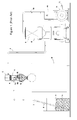
Figure 1 is a schematic front elevation view of a conventional reduced pressure transport plant; -
Figure 2 illustrates an enlarged scale detail of the plant ofFig. 1 in a first operating position; -
Figure 3 shows the detail ofFig. 2 in a second operating position; -
Figure 4 is a diagrammatic view of a centralized reduced-pressure transport plant of granular material from several granular material sources and the same number of transforming machines of the same material; -
Figure 5 shows a partial, schematic view on an enlarged scale of a cleaning device of the granular material conveyance ducts provided in the plant ofFig. 4 ; -
Figure 6 illustrates a centralized reduced pressure transport plant of granular material from several granular material sources and the same number of transforming machines, the plant being provided with a set of cleaning devices as illustratedFig. 5 ; and -
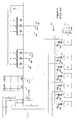
Figure 7 illustrates a schematic view of a further embodiment of a reduced pressure transport plant of granular material according to the present invention. - With reference first to
Figs. 1 to 3 , it will be noted that a conventional reduced pressure transport plant of granular material comprises acontainer 1 of any suitable type containing a specific amount ofgranular material 1a to be transported, a fluidizing lance member 2 drawing ingranular material 1a, e. g. formed by a substantially rigid tube, intended to capture material granules and mix them with air, as will be further described below. The lance member 2 is in fluid communication with one end of a tube or hose 3, which can be of both rigid and flexible type and whose other end penetrates in an intermediate portion of a hermetically-sealed receiver-meter device 4 and defines adischarge mouth 3a. - Within the receiver-
meter device 4, at a lower level than that of thedischarge mouth 3a, asmall metering hopper 33 is provided equipped with lower discharge mouth that can be opened and closed by abottom flap 34 supported by a projectingarm 15 in turn pivoted at 35 to the hopper, thereby being arranged to oscillate about a horizontal axis. The discharge mouth is illustrated closed inFig. 2 , while inFig. 3 it is open, in order to dischargegranular material 1a conveyed and collected in themetering hopper 33 into anunderlying hopper 13 set to act as a feed storage of plasticgranular material 1a for a transformer machine generally indicated with M. - The rotatable equipment formed by the
bottom flap 34 and by thesupport arm 15 is provided with acounter-weight 20 that encloses a magnet (not shown in the drawings) and anelectromagnetic alignment sensor 21. With this structure, when granular material is not present in themetering hopper 33, thebottom flap 34 comes to automatically close the discharge mouth of thehopper 33, due to the presence of thecounterweight 20 and the vacuum, and the magnet enclosed in the counterweight aligns with themagnetic sensor 21, thus generating an electrical signal. Such electrical signal is sent, e. g. by means of electric cable, to a receiving unit, as will be further described below. - The transport air of the
granular material 1a coming from thecontainer 1 is separated from the granular material falling inside the receiver-meter 4 and is suctioned, possibly through a first filter 6, via amouth 7a placed in the upper head orportion 5 of the receiver-meter 4 and in fluid communication with one end of a rigid orflexible duct 7, whose other end leads to acyclone filtering group 8. The latter is equipped with inner filter 9 with high filtering capacity and traps even small particles dispersed in the air that crosses it. - From the
cyclone filtering group 8, aflexible duct 10 departs which is connected to a vacuum source, typically to the suction mouth of a vacuum pump or ablower 11 provided with anelectric control panel 14, that expels the air drawn through theducts duct 12. - If the
vacuum pump 11 is stopped, the granular material possibly contained in themeter hopper 33, due to the lack of vacuum and the weight of the granular material therein contained, causes the discharge mouth of thehopper 33 to open, so that any granular material is discharged into theunderlying hopper 13. - When the magnet associated with the
counterweight 20 is aligned with themagnetic sensor 21, an electric control signal is generated that is sent to theelectric panel 14 of the blower orvacuum pump 11, which is thus actuated, giving rise to a new granular material feed cycle. The cycle is timed and can be varied as a function of the size of the receiver-meter 4, of its distance from thecontainer 1 and/or of the type of granular material to be transported. - With a plant of the above-described type, it is possible to carry out the transport of plastic granular material for distances up to 200 m, even for feeding several machines for the transformation of plastic granular materials, in which case the plant is called a "centralized" transport plant in jargon. One example of a centralized reduced pressure transport plant is illustrated in
Fig. 4 , where a single suction unit (pump or blower) 11 is provided and acyclone filtering group 8 is arranged upstream of the suction unit. The various receivers-meters 4 of number n, for example 28 receivers-meters, are in fluid communication with thefiltering group 8 by means of acommon duct 70, termed "vacuum line" in jargon. In other words, thevacuum line 70 can serve a number n of transformation machines M1, M2.....Mn. Preferably, the receiver-meters 4 are each equipped with an interception valve (not illustrated in the drawings) placed inside itsrespective head 5, which is drivable by a respective electropneumatic valve VE1, VE2....., VEn, in turn, controlled by a suitable electronic control unit ECU set to control every zone of the plant, in particular energizing at one time one or another receiver-meter 4 according to operating needs. This plant type is particularly indicated for conveying granular material over relatively large distances, on the order of 200 m. In this case, it is necessary to employ a verypowerful suction unit 11, since the loss loads must be overcome, which are obviously much greater for high distances, keeping in mind that installing several suction units would lead to prohibitive costs. - With every cycle, the conveyance line L1, L2,...., Ln is hit with a pre-established quantity of air and granular material and at the end of every cycle it is completely evacuated of granular material, owing to the presence of an interceptor device, termed "cleaning valve", VP1, VP2....., VPn provided for each receiver-
meter 4, so that when thesuction unit 11 is stopped, the conveyance line L1, L2,...., Ln is emptied. One such plant is in particular used when one must feed, in subsequent cycles, different granular materials to several machines for the transformation of plastic granular material. - Should the conveyance line L1, L2,...., Ln be not emptied at the beginning of every cycle, the tubing could be contaminated or even obstructed by granules of the previously conveyed material and the
suction unit 11 may not be able to create a sufficient suction effect suitable for ensuring both the evacuation of the air and the transport of granular material. - One of the problems that occurs in conventional reduced pressure transport plants of this type is that the flow speed or intensity of the granules inside the tubes does not remain constant, but varies, up to even doubling, with the variation of the work conditions.
- In
Figure 5 , a typical cleaning valve is illustrated, indicated with VP1 and inserted in the feed duct 3 of a respective receiver-meter 4. It comprises a valve body, in which an air and granularmaterial inlet mouth 40 is obtained, where e. g. anozzle 41 is provided for a first section of duct 3 in communication with the respective lance member 2. An outlet mouth is also provided in the valve body, preferably placed in offset position with respect to theinlet mouth 40, from which a second section of the feed duct 3 departs, directed to the receiver-meter 4. In front of the inlet mouth, but on opposite side thereof, a receiving opening is formed in the valve body for a linear actuator device 43 of any suitable type, which is set to control a preferablyconical plug element 44, moving it on command of the electronic control unit ECU between a closed position, as shown inFig. 5 , in which it closes theinlet mouth 40 or thenozzle 41, and an open position far from themouth 40 or thenozzle 41. - An ambient
air inlet opening 45 is also formed in the valve body, externally provided with afilter 46, whereas within the valve bodysuch opening 45 can be intercepted by theplug element 44 when it is moved into open position by the actuator 43. With this structure of the cleaning valve VP1, when the plug element is moved into closed position of theinlet mouth 40 or of thenozzle 41, only ambient air is suctioned through thefilter 46 and thus through the receiver-meter 4 in order to carry out a cleaning cycle of the tubing. - In a granular material transport cycle, i.e. when the cleaning valve VP1 places the tube section 3 in communication with the lance member 2, with the second section of tube 3 in communication with its respective receiver-
meter 4, due to the reduced pressure created by thesuction unit 11, the granular material is caused to move and accelerate until it reaches a so-called "equilibrium" speed. - The initial acceleration imparted to the granular material mainly depends on the fact that the granular material at the start finds the second section of tube 3, that directly communicating with the receiver-
meter 4, to be completely empty, and as it receives granular material, the load losses of the internal air flow and the friction against the walls increase, and consequently the speed of the suctioned air flow decreases. These factors ensure that the acceleration imparted to the plasticgranular material 1a gradually decreases until it reaches the equilibrium speed. - The same occurs when at the cycle's end the linear actuator 43 moves the
plug element 44 into closed position against theinlet mouth 40 or thenozzle 41, thus allowing the suction of ambient air through thefilter 46 in order to start the cleaning of the tubing. In this step, the speed of the plastic material granules present in the second section of the duct 3 tends to progressively increase, until complete emptying of the tubing has been obtained, achieving flow intensity values that are even double that of the equilibrium speed. At one such speed, theplastic material granules 1a scrape against the walls of the tubes, in particular at the curved sections of the tubes; consequently, a thin film is deposited, especially at rough areas of the material (usually metal) composing the tube, giving rise to the angelhair phenomenon mentioned above. - With reference to the embodiment of the present invention illustrated in
Figure 6 , a reduced pressure transport plant of granular materials comprises one or more granular material containers orsilos 100, from which such material is suctioned by means of one ormore suction units 11, e. g. formed by one or more vacuum pumps, and a gaseous medium or fluid, e. g. air or nitrogen, which brings thegranular material 1 a therewith. - The
various containers 100 ofgranular material 1a are in fluid communication by means of a respective duct L1, L2,..., Ln with a respective receiver-meter RD1, RD2,..., RDn, each duct L1,...Ln being interceptable by a respective cleaning valve VP1, VP2,..., VPn. - The outlet for air from each receiver-meter RD1, RD2,..., RDn is connected to a common vacuum line LV, in which an air flow rate meter MP is provided, e. g. comprising a Venturi meter of any suitable type, which is electrically connected with an electronic control unit ECU.
- Moreover, the plant comprises one variator device DV per
suction unit 11, which is arranged to vary the power or typically the rotation speed of the electric motor (not shown in the drawings) for actuating the respective suction units. Such speed variator device is preferably of electronic type, e. g. a so-called inverter, of any suitable type, which is intended to vary the frequency of the power supply current to the motor of its respective suction unit, and is in turn controllable by the electronic control unit ECU. - The air flow rate meter MP is designed to send electrical signals to the input of the electronic control unit ECU which are correlated to the air flow rate in the vacuum line LV. The electronic control unit ECU processes the signals received in input in order to generate control signals to be sent to the speed variator device(s) (inverter(s)) DV, which correspondingly vary the frequency of the power supply current to the motor of the suction unit(s) 11, 11a. In this manner, the depressurization or vacuum level and consequently the speed of the
granular material 1a traveling along the tubes is adjusted as a function of the variations in the transport conditions of the material, which as stated above can vary when passing, for example, from the filling step to the unloading step of the granular material in the various suction lines L1, L2,..., Ln of thegranular material 1a. - More particularly, since there is a correlation between the parameters formed by flow rate, air speed and the vacuum level inside the tubes, the electronic control unit ECU through the inverter(s) DV modulates the rotation speed of the motor, and thus the power of each
suction unit 11, thereby producing an initial acceleration ramp of thegranular material 1 a as a function of the variation of the depressurization or vacuum level. Subsequently, when an increase occurs of the load losses following the deposit of granular material on the inner surface of the vacuum line LV, the flow rate meter MP detects the flow rate variation caused by the load losses, which results in the variator device(s) DV (inverter(s)) increasing its rotation speed and thus the power of therespective suction unit granular material 1a movement speed constant over time along the ducts, or thus obtaining, if the circumstances require it, a variable speed progression over time. - In the tube cleaning step, on the other hand, the reverse process occurs. Once the feed of
granular material 1a to the respective receiver-meter RD1, RD2,..., RDn is stopped, the air speed in the reduced pressure tubing increases. The flow rate meter MP consequently detects a flow rate variation and sends a corresponding signal to the electronic control unit ECU, which will consequently drive the speed variator device(s) DV. - A control microprocessor (not shown), e. g. a PLC of any suitable type placed in the electronic control unit ECU, is set to create different transport condition profiles as a function of the type of
granular material 1 a to be transported. Typically, in a first storage portion of the control microprocessor, a table is pre-stored, which is none other than a list of a first array of plasticgranular materials 1a with their respective characteristic parameters of their respective optimal transport speed profile. In a second storage portion, the operator of the reduced pressure transport plant can store the parameters of possible new granular materials, defined "experimental", through a suitable user interface, e. g. consisting of a video unit (monitor) and access means to the microprocessor for the data insertion, e. g. a keyboard and/or a mouse. Preferably, the user interface is a graphical interface with objects of "touch-screen" type. - With such device, it is possible to process any
granular material 1 a, feeding it at the most suitable speed, without generating powders, eliminating possible speed peaks, reducing the transport tube wear by the conveyed granular materials, optimizing the various cycles in a completely automatic manner, without risking the obstruction of the transport ducts, adapting the performances and productivity of the plant as a function of the transported granular material and eliminating every impact of the filtering effect on the speed and/or reduced pressure level prevailing during the transport. - According to an advantageous variation of a reduced pressure pneumatic transport plant according to the present invention, the
suction units - A reduced pressure transport plant as described above can be used with only one
suction unit 11 in order to ensure the feed ofgranular material 1 a to a single transformation machine or array of transformation machines M1, M2, ..., Mn. - Another reduced pressure transport plant of granular material according to the present invention will be described below with reference to
Figure 7 , where the same reference numbers are used for indicating components already described with reference to the embodiment ofFig. 6 . Such plant provides for the presence of asuction unit 11 equipped with inverter DV. Advantageously, one or moreauxiliary suction units 11a can be connected in parallel to thesuction unit 11, also equipped with inverter DV, similar to that described with reference to the embodiment illustrated inFig. 6 . - Also provided is a reduced pressure storage tank SER of any suitable type, into which the various vacuum lines LV1, LV2,..., LVn converge of the respective receivers-meters RD1, RD2,..., RDn serving a respective transformation machine M1, M2,..., Mn. The tank SER is arranged upstream of the
suction unit 11. - Preferably, downstream of the tank SER, a filtering group F is provided for, to which the air suctioned by the tank SER is directed in order to be filtered before reaching the suction unit(s) 11, 11 a. Moreover, according to such embodiment a differential pressure meter DPS is also provided for of any suitable type, intended to measure the load loss due to the obstruction of the filtering group F and to generate respective electrical signals to be sent to the input of an electronic control unit ECU.
- Starting from each
container 100 of granular material to be transferred, a feed duct L1, L2, ..., Ln departs that is intended to feed granular material to a respective receiver-meter RD1, RD2, ..., RDn. Provided in series in each conveyance line L1, L2, ..., Ln is both a cleaning line VP1, VP2, ..., VPn and a detection means RS1, RS2, ..., RSn of the speed of the granular material that moves inside the respective feed line, e. g. comprising a sensor known in the state of the art and based on the interaction of the flow of the solid material moving in the feed line with a suitable electromagnetic signal, e. g. low energy microwaves, which send corresponding control signals to the input of the electronic control unit ECU. - In each vacuum line LV1, LV2, ..., LVn, the following are provided in series:
- an air flow rate meter VT1, VT2, ..., VTn, e. g. comprising a Venturi meter of any suitable type,
- a pressure meter PS1, PS2, ..., PSn intended to measure the pressure in the respective vacuum line LV1, LV2, ..., LVn and to send corresponding signals to the input of the electronic control unit ECU, and
- a motorized valve MV1, MV2, ..., MVn of any suitable type arranged to maintain a correct reduced pressure or vacuum level in the respective vacuum line LV1, LV2, ..., LVn as well as in its respective receiver-meter RD1, RD2, ..., RDn.
- The electronic control unit ECU is designed to process the signals received in its input and to send, if deemed necessary, control signals to one or more of the motorized valves MV1, MV2, ..., MVn, thereby obtaining a desired speed profile for each specific granular material to be fed to the transformation machines M1, M2, ..., Mn, as well as to the speed variator device(s) DV, which modulate the rotation speed and thus the power of the
respective suction units - The electronic control unit ECU is suitable for diversifying the functioning parameters in the various vacuum lines LV1, LV2, ..., LVn and in its respective receiver-meters RD1, RD2, ..., RDn based on the pre-established movement speed for every type of granular material inside each conveyance line L1, L2, ..., Ln.
- Of course, also in this embodiment, through a control microprocessor of the electronic control unit ECU, e. g. a PLC, of any suitable type, it is possible to store different transport condition profiles as a function of the material type for every transport line.
- Alternatively, if it is desired to diminish the plant costs, in place of the pressure meters PS1, PS2, ..., PSn a single pressure meter can be provided, such meter being designed to carry out the measurement of the reduced pressure in the vacuum storage tank SER and to send corresponding control signals to the input of the electronic control unit ECU.
- The above-described plant is susceptible to numerous modifications and variations within the protection scope as defined by the claims.
- Thus, in place of suction means of the air or another gaseous fluid, pressing or pressurizing means can be provided, obtaining entirely similar results.
Claims (18)
- A plant for the transport of granular material comprising at least one container (100) for at least one granular material (1a) to be transported, at least one receiver-meter group (RD1, RD2,..., RDn) designed to receive granular material from said at least one container (100), at least one conveyance duct (L1, L2, ..., Ln) of said granular material from said at least one container (100) to said at least one receiver-meter group (RD1, RD2, ..., RDn), depressurization-pressurization means (11, 11a) arranged to suction/inject a gaseous medium from/into said at least one container (100), and at least one vacuum duct (LV; LV1, LV2, ..., LVn) between said at least one receiver-meter group (RD1, RD2, ..., RDn) and said depressurization-pressurization means (11, 11a), thereby creating a flow of said granular material and said gaseous medium in said at least one conveyance duct or line (L1, L2, ..., Ln) directed to said at least one receiver-meter group (RD1, RD2, ..., RDn) and a flow of gaseous medium between said at least one receiver-meter group (RD1, RD2, ..., RDn) and said depressurization-pressurization means, characterized in that it comprises detection means of parameters of said flow (MP; VT1, VT2, ..., VTn) located in said at least one vacuum duct or line (LV; LV1, LV2,..., LVn), adjusting means of the power (DV) of said depressurization/pressurization means and electronic control means (ECU) designed to receive in input control signals from said speed detection means (MP; VT1, VT2, ..., VTn) and to emit control signals in output for driving said adjusting means (DV).
- A plant according to claim 1, characterized in that said depressurization-pressurization means (11, 11a) comprises at least one rotatable component actuated by an electric motor and said power adjusting means (DV) comprise at least one rotation speed variation device of said at least one rotating component of said depressurization-pressurization means (11, 11a).
- A plant according to claim 2, characterized in that said power adjusting means (DV) comprises an inverter, designed to vary the frequency of the power supply current to said electric motor in said depressurization-pressurization means (11, 11a).
- A plant according to any preceding claim, characterized in that said depressurization-pressurization means (11, 11a) comprises at least one vacuum pump or blower.
- A plant according to any preceding claim, characterized in that said detection means of parameters of said flow (MP; VT1, VT2, ..., VTn) comprises direct and/or indirect measuring means of air speed in said at least one vacuum duct or line (LV; LV1, LV2,.... LVn).
- A plant according to claim 5, characterized in that said measuring means comprises at least one flow rate meter (LV; LV1, LV2,..., LVn).
- A plant according to any preceding claim, characterized in that it comprises at least one reduced pressure storage tank (SER) arranged upstream of said at least one suction unit (11, 11 a) and in fluid communication with said at least one vacuum line (LV1, LV2,..., LVn) of said at least one receiver-meter group (RD1, RD2,..., RDn).
- A plant according to claim 7, characterized in that it comprises, downstream of said at least one tank (SER), at least one filtering group (F) through which the air suctioned from said at least one tank (SER) is caused to flow.
- A plant according to claim 8, characterized in that it comprises a differential pressure meter means (DPS) arranged to measure possible load losses due to obstruction of said at least one filtering group (F) and to generate respective electrical signals to be sent to the input of said electronic control means (ECU).
- A plant according to claim 9, characterized in that it comprises in said at least one vacuum line (LV1, LV2, ..., LVn) and in series:- a meter means of the air flow rate (VT1, VT2, ..., VTn),- a pressure meter means (PS1, PS2, ..., PSn) intended to measure the pressure in a respective vacuum line (LV1, LV2, ..., LVn) and to send respective signals to the input of said electronic control means (ECU), and- valve means (MV1, MV2, ..., MVn) arranged to maintain a correct reduced pressure or vacuum level in a respective vacuum line (LV1, LV2, ..., LVn) as well as in a respective receiver-meter (RD1, RD2, ..., RDn).
- A plant according to claim 10, characterized in that said valve means comprises motorized valve means (MV1, MV2, ..., MVn) adjusted by said electronic control means (ECU).
- A plant according to any preceding claim, characterized in that it comprises in each conveyance line (L1, L2,..., Ln), arranged in series, a respective cleaning valve (VP1, VP2, ..., VPn) and a respective detection means (RS1, RS2, ..., RSn) of the speed of the granular material which moves inside its respective conveyance line, said detection means being intended to send a signal to said electronic control means (ECU).
- A plant according to any preceding claim, characterized in that it comprises a user interface comprising a video unit and data insertion means, said user interface being intended to store, in said electronic control means, treatment parameters and characteristics related to the granular material(s) to be treated.
- A plant according to any preceding claim, characterized in that said electronic control means (ECU) comprises a storage portion designed to store characteristic data of the transport speed progression of specific granular materials.
- A control process of the conveyance speed of a granular material along at least one conveyance line between at least one container of the granular material to be conveyed and at least one receiver-meter group (RD1, RD2, ..., RDn) of the same comprising:- the application of a depressurization-pressurization to said granular material through at least one conveyance duct (L1, L2, ..., Ln) extending between said at least one container and said at least one receiver-meter group (RD1, RD2, ..., RDn) and through said at least one vacuum line or duct (LV; LV1, LV2, ..., LVn), whereby suctioning/injecting a gaseous medium from/into said at least one container (100) and to create a flow of said granular material and said gaseous medium along said at least one conveyance duct (L1, L2, ..., Ln) directed to said at least one receiver-meter group (RD1, RD2, ..., RDn) and a flow of gaseous medium between said at least one receiver-meter group (RD1, RD2, ..., RDn) and depressurization-pressurization means (11, 11a), characterized in that it comprises:- detecting parameters of said gaseous flow in said at least one vacuum line or duct (LV; LV1, LV2,..., LVn), and- adjusting said flow by varying the depressurizing-pressurizing power of said depressurization-pressurization means as a function of the detected parameters of said flow.
- A process according to claim 15, characterized in that said step of detecting parameters of said gaseous flow comprises at least one step of detecting the speed of said at least one granular material in a respective conveyance duct (L1, L2, ..., Ln).
- A process according to claim 15 or 16 carried out by means of a plant according to claim 10, characterized in that it comprises an adjusting step of said valve means (MV1, MV2, ..., MVn) designed to maintain a correct reduced pressure or vacuum level in a respective vacuum line (LV1, LV2, ..., LVn).
- A process according to any claims 15 to 17, characterized in that said plant comprises depressurization-pressurization means connected in parallel with each other, said process comprising the steps of:- controlling the alternating or simultaneous actuation of said depressurization-pressurization means as a function of the parameters of said flow detected in said detection step.
Applications Claiming Priority (1)
| Application Number | Priority Date | Filing Date | Title |
|---|---|---|---|
| IT000083A ITVR20070083A1 (en) | 2007-06-12 | 2007-06-12 | PLANT FOR PNEUMATIC TRANSPORT AT CONTROLLED SPEED OF GRANULAR MATERIAL AND PROCEDURE FOR THE CONTROL OF CONVEYANCE SPEED |
Publications (3)
| Publication Number | Publication Date |
|---|---|
| EP2003075A1 true EP2003075A1 (en) | 2008-12-17 |
| EP2003075B1 EP2003075B1 (en) | 2011-01-19 |
| EP2003075B2 EP2003075B2 (en) | 2018-06-20 |
Family
ID=39708399
Family Applications (1)
| Application Number | Title | Priority Date | Filing Date |
|---|---|---|---|
| EP08158060.7A Active EP2003075B2 (en) | 2007-06-12 | 2008-06-11 | Plant for the controlled-speed pneumatic transport of granular material and conveyance speed control process |
Country Status (9)
| Country | Link |
|---|---|
| US (3) | US8360691B2 (en) |
| EP (1) | EP2003075B2 (en) |
| KR (1) | KR101503414B1 (en) |
| CN (1) | CN101323399B (en) |
| AT (1) | ATE495989T2 (en) |
| DE (1) | DE602008004589D1 (en) |
| ES (1) | ES2361817T5 (en) |
| HK (1) | HK1126461A1 (en) |
| IT (1) | ITVR20070083A1 (en) |
Cited By (8)
| Publication number | Priority date | Publication date | Assignee | Title |
|---|---|---|---|---|
| EP2045003A1 (en) * | 2007-09-27 | 2009-04-08 | Mann + Hummel ProTec GmbH | Device for conveying and mixing bulk material |
| EP2239051A1 (en) * | 2009-04-01 | 2010-10-13 | Mann + Hummel GmbH | Processing device for bulk material |
| ITRM20130260A1 (en) * | 2013-05-02 | 2014-11-03 | Novatec S R L | PNEUMATIC TRANSPORT SYSTEM, PARTICULARLY FOR FRAGILE ITEMS |
| ITPD20130142A1 (en) * | 2013-05-22 | 2014-11-23 | Moretto Spa | PNEUMATIC TRANSPORT SYSTEM OF GRANULAR MATERIAL AND METHOD OF CHECKING THAT SYSTEM |
| US9440802B2 (en) | 2007-06-12 | 2016-09-13 | Moretto S.P.A. | Plant for the controlled-speed pneumatic transport of granular material and conveyance speed control process |
| EP3100968A1 (en) * | 2015-06-01 | 2016-12-07 | Xerex Ab | Device and system for pneumatic transport of material |
| US10399797B2 (en) | 2016-08-29 | 2019-09-03 | Shick Solutions, Inc. | Flow control apparatus for carrier fluid |
| WO2019170534A1 (en) * | 2018-03-05 | 2019-09-12 | Windmöller & Hölscher Kg | Suction device for suctioning extrusion material to a storage container of an extrusion device |
Families Citing this family (55)
| Publication number | Priority date | Publication date | Assignee | Title |
|---|---|---|---|---|
| EP2254818A1 (en) * | 2008-01-28 | 2010-12-01 | Johann Haberl | Tubing conduit system, a method for control thereof and the use thereof |
| US7940188B2 (en) * | 2008-02-07 | 2011-05-10 | Veltek Associates, Inc. | Air sampling system having a plurality of air sampling devices with their own flow switches |
| BRPI0909479A2 (en) * | 2008-03-28 | 2015-12-22 | Nippon Catalytic Chem Ind | method for producing a water absorbing resin |
| US9731914B2 (en) * | 2008-11-06 | 2017-08-15 | Michael J. Rasner | Pneumatic convey system with constant velocity pickup |
| AT508720B1 (en) * | 2009-08-20 | 2012-05-15 | Wittmann Kunststoffgeraete | METHOD FOR THE AUTOMATIC LOADING OF A CONVEYOR PIPE WITH BULK GOODS |
| IT1397049B1 (en) * | 2009-12-24 | 2012-12-28 | Wam Spa | LOADING EQUIPMENT FOR A SILO |
| DK2537148T3 (en) * | 2010-02-18 | 2021-09-27 | Veltek Ass Inc | IMPROVED AIR SAMPLING SYSTEM |
| US8591098B2 (en) * | 2010-05-05 | 2013-11-26 | E-Loaders Company, Llc | Apparatus and method for material blending |
| KR100988357B1 (en) * | 2010-07-06 | 2010-10-18 | 주식회사 비티에스이엔지 | A system for transferring powder using venturi ejector |
| US8905681B2 (en) * | 2010-07-26 | 2014-12-09 | Pelletron Corporation | Pneumatic conveying process for particulate materials |
| KR101938153B1 (en) * | 2012-05-03 | 2019-01-14 | 엔박 에이비 | Method of controlling operation of a pneumatic conveying system |
| NL1039764C2 (en) * | 2012-08-17 | 2014-02-18 | J O A Technology Beheer B V | A method of, a control system, a device, a sensor and a computer program product for controlling transport of fibrous material in a transport line of a pneumatic conveying system. |
| JP2014091117A (en) * | 2012-11-07 | 2014-05-19 | Fts:Kk | Transportation system and transportation method of granular body material |
| JP2014091118A (en) * | 2012-11-07 | 2014-05-19 | Fts:Kk | Powder-removing device for granular material, and powder-removing system for crushed material equipped with the same |
| WO2014155655A1 (en) * | 2013-03-29 | 2014-10-02 | 株式会社松井製作所 | Material conveyance device and material conveyance method |
| RU2535821C1 (en) * | 2013-10-31 | 2014-12-20 | Закрытое Акционерное Общество "Твин Трейдинг Компани" | Air vacuum device for transfer of loose materials with high weight concentration |
| US20150321860A1 (en) * | 2014-02-20 | 2015-11-12 | Stephen B. Maguire | Vacuum powered resin loading system without central control |
| US10138075B2 (en) * | 2016-10-06 | 2018-11-27 | Stephen B. Maguire | Tower configuration gravimetric blender |
| US10414083B2 (en) | 2014-02-20 | 2019-09-17 | Novatec, Inc. | Multiple sensor resin delivery optimizing vacuum pump operation |
| US10280015B2 (en) | 2014-02-20 | 2019-05-07 | Stephen B. Maguire | Method for adjustably restricting air flow and apparatus therefor |
| US20160185537A1 (en) * | 2014-02-20 | 2016-06-30 | Novatec, Inc. | Resin delivery method and apparatus using multiple sensors for optimal vacuum pump operation |
| US10144598B2 (en) | 2014-02-20 | 2018-12-04 | Novatec, Inc. | Variable frequency drive combined with flow limiter set for limiting flow to selected level above design choice |
| US10175701B2 (en) | 2014-02-20 | 2019-01-08 | Stephen B. Maguire | Air flow regulator with detector and method for regulating air flow |
| US9937651B2 (en) | 2014-02-20 | 2018-04-10 | Novatec, Inc. | Resin delivery apparatus and method with plural air flow limiters |
| US10179708B2 (en) | 2014-02-20 | 2019-01-15 | Maguire Products, Inc. | Granular material delivery system with air flow limiter |
| WO2015157099A1 (en) * | 2014-04-07 | 2015-10-15 | Nordson Corporation | Feed center for dense phase system |
| CA2893065A1 (en) * | 2014-05-29 | 2015-11-29 | Carl D. Celella | Vacuum operated wood pellet handling, filtering and dispensing apparatus, system and methods of use thereof |
| US9939416B2 (en) | 2014-08-28 | 2018-04-10 | Veltek Assoicates, Inc. | Programmable logic controller-based system and user interface for air sampling in controlled environments |
| US9363943B2 (en) | 2014-11-13 | 2016-06-14 | Cnh Industrial America Llc | Self-aligning head bracket system and method |
| US10131506B2 (en) | 2014-12-09 | 2018-11-20 | Maguire Products, Inc. | Selective matrix conveyance apparatus and methods for granular resin material |
| CN104495390B (en) * | 2014-12-10 | 2016-08-24 | 大唐彬长发电有限责任公司 | A kind of delivery pump throttle orifice electrical heat tracing system |
| US10179696B2 (en) | 2015-01-27 | 2019-01-15 | Novatec, Inc. | Variable opening slide gate for regulating material flow into airstream |
| CN107207101A (en) * | 2015-02-12 | 2017-09-26 | 艾普尼公司 | Automatic vacuum activated controllers |
| US10138076B2 (en) * | 2015-02-25 | 2018-11-27 | Stephen B. Maguire | Method for resin delivery including metering introduction of external air to maintain desired vacuum level |
| CA2980115A1 (en) | 2015-03-19 | 2016-09-22 | Ipeg, Inc. | Material delivery system |
| CN104860072A (en) * | 2015-06-03 | 2015-08-26 | 安徽省铜陵县牛山矿业有限责任公司 | Calcium carbonate pneumatic conveying system |
| JP2017024882A (en) * | 2015-07-27 | 2017-02-02 | 株式会社松井製作所 | Feeder for granular powder material |
| US10494200B2 (en) * | 2016-04-25 | 2019-12-03 | Chevron Phillips Chemical Company Lp | Measurement of product pellets flow rate |
| NO343343B1 (en) * | 2016-11-21 | 2019-02-04 | Norsk Hydro As | Apparatus and method for feeding doses of fluidisable materials |
| CN106743673B (en) * | 2017-02-16 | 2019-11-26 | 珠海优特智厨科技有限公司 | A kind of kitchen material-transporting system and kitchen automatic cooking system |
| EP3530599A1 (en) * | 2018-02-27 | 2019-08-28 | Piab Ab | Vacuum conveyor system |
| CA3038323A1 (en) * | 2018-03-28 | 2019-09-28 | Ipeg, Inc. | System and method using telemetry to configure control systems for pneumatic conveying systems |
| CN109625980B (en) * | 2018-12-29 | 2023-03-14 | 西安西热节能技术有限公司 | Pneumatic ash removal system and ash conveying time optimization method |
| AT521693B1 (en) * | 2019-01-11 | 2020-04-15 | Nowe Gmbh | Method for controlling a device for metering granules and metering device for metering granules |
| CN109969794A (en) * | 2019-04-30 | 2019-07-05 | 北京长峰金鼎科技有限公司 | A kind of powder negative-pressure conveying system and method |
| EP3736234B1 (en) * | 2019-05-10 | 2024-07-03 | Coperion GmbH | Conveyor system and method for the pneumatic conveying of plastic granulate |
| US11999577B2 (en) | 2019-11-18 | 2024-06-04 | George Archambault | Methods and systems for managing airflow in conduits and pneumatic tubes |
| PL3882185T3 (en) * | 2020-03-19 | 2024-04-29 | Calderys France Sas | Pumping apparatus |
| US11365071B2 (en) * | 2020-04-28 | 2022-06-21 | IPEG, Inc | Automatic tuning system for pneumatic material conveying systems |
| US11565892B2 (en) | 2020-07-08 | 2023-01-31 | Trans-Vac Systems LLC | Methods and systems for operation of a vacuum transport system |
| CN111957269A (en) * | 2020-08-04 | 2020-11-20 | 中冶北方(大连)工程技术有限公司 | Movable lime milk preparation system |
| US20230009644A1 (en) * | 2021-07-08 | 2023-01-12 | Industrial Vacuum Transfer Services Usa, Llc | Assemblies and methods for material extraction |
| DE102021118548A1 (en) * | 2021-07-19 | 2023-01-19 | CiTEX Holding GmbH | Suction conveying device and method for suction conveying of bulk material |
| KR102671615B1 (en) * | 2023-08-25 | 2024-06-03 | (주)티에스아이 | Powder supply apparatus |
| CN117183158B (en) * | 2023-11-03 | 2024-01-19 | 贵州天润达科技有限公司 | Polyolefin resin feeding device and feeding method thereof |
Citations (6)
| Publication number | Priority date | Publication date | Assignee | Title |
|---|---|---|---|---|
| GB1428498A (en) * | 1973-07-06 | 1976-03-17 | Waeschle Maschf Gmbh | Method and apparatus for pneumatically conveying material |
| JPS6067325A (en) * | 1983-09-20 | 1985-04-17 | Babcock Hitachi Kk | Granular powder collecting device |
| DE19517793A1 (en) * | 1995-05-15 | 1996-11-21 | Protekno Puzair Oy | Arrangement with a suction device for solids |
| JPH09202448A (en) | 1996-01-25 | 1997-08-05 | Sumitomo Heavy Ind Ltd | Method and equipment for controlling ash-carriage of electric dust collector |
| US5813801A (en) * | 1996-06-28 | 1998-09-29 | Mac Equipment, Inc. | Dense phase particulate conveying system and method with continuous air leakage management |
| FR2812864A1 (en) * | 2000-08-12 | 2002-02-15 | Mann & Hummel Pro Tee Gmbh | DEVICE FOR TRANSFERRING BULK PRODUCTS |
Family Cites Families (24)
| Publication number | Priority date | Publication date | Assignee | Title |
|---|---|---|---|---|
| US3870375A (en) * | 1971-11-02 | 1975-03-11 | Nordson Corp | Powder spray system |
| US4318643A (en) * | 1979-12-28 | 1982-03-09 | Ab Svenska Flaktfabriken | Apparatus for conveying waste materials by suction |
| JPS57207826A (en) * | 1981-06-17 | 1982-12-20 | Hideo Nagasaka | Measuring device for flow rate of pulverulent body |
| US4718795A (en) * | 1982-02-18 | 1988-01-12 | Acf Industries, Incorporated | Unloading outlet assembly |
| CA1202343A (en) * | 1982-08-17 | 1986-03-25 | Thomas G. Smith | Automatic pneumatic feeder |
| US4464184A (en) * | 1982-11-22 | 1984-08-07 | United States Steel Corporation | Apparatus and method for the control of the precoating of an effluent filtration baghouse utilizing clean side pressure measurement |
| US4770611A (en) * | 1986-05-07 | 1988-09-13 | The Young Industries, Inc. | Product pump assembly |
| US4907892A (en) * | 1989-02-02 | 1990-03-13 | Fuller Company | Method and apparatus for filling, blending and withdrawing solid particulate material from a vessel |
| US6036407A (en) * | 1997-09-03 | 2000-03-14 | Exxon Chemical Patents Inc. | Solids conveying system for compacted, friable solids that can not be pushed or compressed |
| SE510507C2 (en) * | 1998-01-09 | 1999-05-31 | Paer Wellmar | Method and plant for pneumatic transport of solid particles |
| DE19912277A1 (en) * | 1999-03-18 | 2000-09-21 | Mann & Hummel Protec Gmbh | Device for conveying plastic granulate |
| DE29914892U1 (en) † | 1999-08-25 | 1999-12-30 | Siemens AG, 80333 München | Control device for volume flow control, in particular of a blower |
| DE10113249A1 (en) | 2001-03-19 | 2002-10-02 | Siemens Ag | Pressure generator for flowing media |
| US20050039816A1 (en) * | 2003-06-20 | 2005-02-24 | Maguire Stephen B. | Vacuum powered method and apparatus for wirelessly handling and conveying granular material |
| US7228990B2 (en) * | 2003-12-15 | 2007-06-12 | Polymer Group, Inc. | Unitized fibrous construct dispensing system |
| DE102005003620A1 (en) * | 2005-01-26 | 2006-08-03 | Lanxess Deutschland Gmbh | Method and device for pneumatic conveying of poorly flowing bulk material |
| GB0523338D0 (en) * | 2005-11-16 | 2005-12-28 | Inbulk Technologies Ltd | Vacuum conveying velocity control device |
| ES2340001T3 (en) * | 2005-11-21 | 2010-05-27 | Mannkind Corporation | APPARATUS AND PROCEDURE FOR DISPENSATION AND DUST DETECTION. |
| US8113745B2 (en) * | 2006-05-31 | 2012-02-14 | Sintokogio, Ltd. | Pressure tank, an device for feeding powder to a conveying pipe, and its feeding method, and method for determining feeding intervals of powder to the conveying pipe |
| ITVR20070083A1 (en) | 2007-06-12 | 2008-12-13 | Moretto Spa | PLANT FOR PNEUMATIC TRANSPORT AT CONTROLLED SPEED OF GRANULAR MATERIAL AND PROCEDURE FOR THE CONTROL OF CONVEYANCE SPEED |
| KR101577593B1 (en) * | 2008-05-26 | 2015-12-15 | 가부시키가이샤 후지와라테크노아트 | Method for sterilization of powdery or granular substances and apparatus for the sterilization by the method |
| IT1391389B1 (en) * | 2008-10-06 | 2011-12-13 | Bazzica Engineering Di Carlo Bazzica & C S A S | METHOD FOR COLOR CHANGING IN A MOLDING MACHINE OF EXPANDED PLASTIC MATERIAL AND IMPLEMENTING MOLDING MACHINE |
| US8430605B2 (en) * | 2009-01-21 | 2013-04-30 | Jeffrey Dietterich | Pneumatic conveyance system including waste airflow electrical power generation |
| US8591098B2 (en) * | 2010-05-05 | 2013-11-26 | E-Loaders Company, Llc | Apparatus and method for material blending |
-
2007
- 2007-06-12 IT IT000083A patent/ITVR20070083A1/en unknown
-
2008
- 2008-06-11 AT AT08158060T patent/ATE495989T2/en active
- 2008-06-11 EP EP08158060.7A patent/EP2003075B2/en active Active
- 2008-06-11 ES ES08158060.7T patent/ES2361817T5/en active Active
- 2008-06-11 DE DE200860004589 patent/DE602008004589D1/en active Active
- 2008-06-11 KR KR1020080054889A patent/KR101503414B1/en active IP Right Grant
- 2008-06-12 CN CN2008101111970A patent/CN101323399B/en not_active Expired - Fee Related
- 2008-06-12 US US12/155,996 patent/US8360691B2/en active Active
-
2009
- 2009-06-04 HK HK09105033A patent/HK1126461A1/en not_active IP Right Cessation
-
2013
- 2013-01-28 US US13/752,323 patent/US9440802B2/en active Active
- 2013-01-28 US US13/752,299 patent/US20130209180A1/en not_active Abandoned
Patent Citations (6)
| Publication number | Priority date | Publication date | Assignee | Title |
|---|---|---|---|---|
| GB1428498A (en) * | 1973-07-06 | 1976-03-17 | Waeschle Maschf Gmbh | Method and apparatus for pneumatically conveying material |
| JPS6067325A (en) * | 1983-09-20 | 1985-04-17 | Babcock Hitachi Kk | Granular powder collecting device |
| DE19517793A1 (en) * | 1995-05-15 | 1996-11-21 | Protekno Puzair Oy | Arrangement with a suction device for solids |
| JPH09202448A (en) | 1996-01-25 | 1997-08-05 | Sumitomo Heavy Ind Ltd | Method and equipment for controlling ash-carriage of electric dust collector |
| US5813801A (en) * | 1996-06-28 | 1998-09-29 | Mac Equipment, Inc. | Dense phase particulate conveying system and method with continuous air leakage management |
| FR2812864A1 (en) * | 2000-08-12 | 2002-02-15 | Mann & Hummel Pro Tee Gmbh | DEVICE FOR TRANSFERRING BULK PRODUCTS |
Cited By (14)
| Publication number | Priority date | Publication date | Assignee | Title |
|---|---|---|---|---|
| US9440802B2 (en) | 2007-06-12 | 2016-09-13 | Moretto S.P.A. | Plant for the controlled-speed pneumatic transport of granular material and conveyance speed control process |
| EP2045003A1 (en) * | 2007-09-27 | 2009-04-08 | Mann + Hummel ProTec GmbH | Device for conveying and mixing bulk material |
| EP2239051A1 (en) * | 2009-04-01 | 2010-10-13 | Mann + Hummel GmbH | Processing device for bulk material |
| ITRM20130260A1 (en) * | 2013-05-02 | 2014-11-03 | Novatec S R L | PNEUMATIC TRANSPORT SYSTEM, PARTICULARLY FOR FRAGILE ITEMS |
| EP2799375A1 (en) * | 2013-05-02 | 2014-11-05 | Novatec S.r.l. | Pneumatic transportation system, particularly for fragile objects |
| KR20140137323A (en) * | 2013-05-22 | 2014-12-02 | 모레토 에스피에이 | Pneumatic transport system of granular material and control method of such system |
| EP2805902A1 (en) * | 2013-05-22 | 2014-11-26 | MORETTO P.A. S.r.l. | Pneumatic transport system of granular material and control method of such system |
| ITPD20130142A1 (en) * | 2013-05-22 | 2014-11-23 | Moretto Spa | PNEUMATIC TRANSPORT SYSTEM OF GRANULAR MATERIAL AND METHOD OF CHECKING THAT SYSTEM |
| US9637320B2 (en) | 2013-05-22 | 2017-05-02 | Moretto S.P.A. | Pneumatic transport system of granular material and control method of such system |
| EP3100968A1 (en) * | 2015-06-01 | 2016-12-07 | Xerex Ab | Device and system for pneumatic transport of material |
| JP2016222463A (en) * | 2015-06-01 | 2016-12-28 | ゼレックス エイビー | Device for air transport of substance and system |
| US9611106B2 (en) | 2015-06-01 | 2017-04-04 | Xerex Ab | Device and system for pneumatic transport of material |
| US10399797B2 (en) | 2016-08-29 | 2019-09-03 | Shick Solutions, Inc. | Flow control apparatus for carrier fluid |
| WO2019170534A1 (en) * | 2018-03-05 | 2019-09-12 | Windmöller & Hölscher Kg | Suction device for suctioning extrusion material to a storage container of an extrusion device |
Also Published As
| Publication number | Publication date |
|---|---|
| US20130209180A1 (en) | 2013-08-15 |
| EP2003075B1 (en) | 2011-01-19 |
| US20130202370A1 (en) | 2013-08-08 |
| KR101503414B1 (en) | 2015-03-24 |
| ITVR20070083A1 (en) | 2008-12-13 |
| HK1126461A1 (en) | 2009-09-04 |
| KR20080109647A (en) | 2008-12-17 |
| CN101323399B (en) | 2013-04-24 |
| EP2003075B2 (en) | 2018-06-20 |
| US8360691B2 (en) | 2013-01-29 |
| US9440802B2 (en) | 2016-09-13 |
| US20080314461A1 (en) | 2008-12-25 |
| DE602008004589D1 (en) | 2011-03-03 |
| CN101323399A (en) | 2008-12-17 |
| ES2361817T3 (en) | 2011-06-22 |
| ES2361817T5 (en) | 2018-10-25 |
| ATE495989T2 (en) | 2011-02-15 |
Similar Documents
| Publication | Publication Date | Title |
|---|---|---|
| EP2003075B2 (en) | Plant for the controlled-speed pneumatic transport of granular material and conveyance speed control process | |
| CN104176506B (en) | The pneumatic conveyer system of granular materials and the control method of pneumatic conveyer system | |
| CN102209475B (en) | Device and method for feeding cut tobacco from a tobacco delivery unit to a tobacco processing machine | |
| US9387995B2 (en) | Powder supplying device and method for automatically cleaning a powder supplying device | |
| JP5370951B2 (en) | Pneumatic transport method and apparatus for bulk material with poor flow | |
| EP3441147B1 (en) | Powder supplying device for a powder coating installation | |
| JP7033076B2 (en) | Operation method of powder transfer device, powder coating device and powder transfer device for transporting coating powder to powder coater | |
| US20070182031A1 (en) | Method and apparatus for conveying material | |
| TW200934714A (en) | Method and apparatus in pneumatic material conveying system | |
| KR20160078360A (en) | Vacuum-pneumatic device for conveying granular materials having high mass concentration | |
| US20100296880A1 (en) | Pneumatic material conveying system | |
| CN109592332A (en) | A kind of hoisting mechanism for fine materials | |
| CN104066660B (en) | Pneumatic material conveying system and method | |
| CN208448848U (en) | A kind of continuous suction and conveying system of titanium white production miberal powder | |
| US3258296A (en) | Pneumatic material conveyor | |
| JP2008272703A (en) | Method of cleaning inside of piping of pneumatic conveyor and pneumatic conveyor | |
| CN207551398U (en) | A kind of material recycling device of pipeline chain conveyor | |
| US6152310A (en) | Powder supply system and powder supplying unit used in the system | |
| CN209412288U (en) | A kind of titanium valve continuous iron removal device | |
| CN209720993U (en) | A kind of high-purity ammonium chloride closed conveying and dosing device | |
| JP2005280877A (en) | Sucked conveying method and device for powder/granular material | |
| CN118339095A (en) | Method and apparatus for handling material in a pneumatic material conveying system | |
| CN109230639A (en) | Cement entrucking dust-extraction unit |
Legal Events
| Date | Code | Title | Description |
|---|---|---|---|
| PUAI | Public reference made under article 153(3) epc to a published international application that has entered the european phase |
Free format text: ORIGINAL CODE: 0009012 |
|
| AK | Designated contracting states |
Kind code of ref document: A1 Designated state(s): AT BE BG CH CY CZ DE DK EE ES FI FR GB GR HR HU IE IS IT LI LT LU LV MC MT NL NO PL PT RO SE SI SK TR |
|
| AX | Request for extension of the european patent |
Extension state: AL BA MK RS |
|
| 17P | Request for examination filed |
Effective date: 20090615 |
|
| AKX | Designation fees paid |
Designated state(s): AT BE BG CH CY CZ DE DK EE ES FI FR GB GR HR HU IE IS IT LI LT LU LV MC MT NL NO PL PT RO SE SI SK TR |
|
| 17Q | First examination report despatched |
Effective date: 20091005 |
|
| GRAP | Despatch of communication of intention to grant a patent |
Free format text: ORIGINAL CODE: EPIDOSNIGR1 |
|
| GRAS | Grant fee paid |
Free format text: ORIGINAL CODE: EPIDOSNIGR3 |
|
| GRAA | (expected) grant |
Free format text: ORIGINAL CODE: 0009210 |
|
| AK | Designated contracting states |
Kind code of ref document: B1 Designated state(s): AT BE BG CH CY CZ DE DK EE ES FI FR GB GR HR HU IE IS IT LI LT LU LV MC MT NL NO PL PT RO SE SI SK TR |
|
| REG | Reference to a national code |
Ref country code: GB Ref legal event code: FG4D |
|
| REG | Reference to a national code |
Ref country code: CH Ref legal event code: EP |
|
| REG | Reference to a national code |
Ref country code: IE Ref legal event code: FG4D |
|
| REF | Corresponds to: |
Ref document number: 602008004589 Country of ref document: DE Date of ref document: 20110303 Kind code of ref document: P |
|
| REG | Reference to a national code |
Ref country code: DE Ref legal event code: R096 Ref document number: 602008004589 Country of ref document: DE Effective date: 20110303 |
|
| REG | Reference to a national code |
Ref country code: NL Ref legal event code: VDEP Effective date: 20110119 |
|
| REG | Reference to a national code |
Ref country code: ES Ref legal event code: FG2A Ref document number: 2361817 Country of ref document: ES Kind code of ref document: T3 Effective date: 20110622 |
|
| LTIE | Lt: invalidation of european patent or patent extension |
Effective date: 20110119 |
|
| PG25 | Lapsed in a contracting state [announced via postgrant information from national office to epo] |
Ref country code: SE Free format text: LAPSE BECAUSE OF FAILURE TO SUBMIT A TRANSLATION OF THE DESCRIPTION OR TO PAY THE FEE WITHIN THE PRESCRIBED TIME-LIMIT Effective date: 20110119 Ref country code: PT Free format text: LAPSE BECAUSE OF FAILURE TO SUBMIT A TRANSLATION OF THE DESCRIPTION OR TO PAY THE FEE WITHIN THE PRESCRIBED TIME-LIMIT Effective date: 20110519 Ref country code: HR Free format text: LAPSE BECAUSE OF FAILURE TO SUBMIT A TRANSLATION OF THE DESCRIPTION OR TO PAY THE FEE WITHIN THE PRESCRIBED TIME-LIMIT Effective date: 20110119 Ref country code: LT Free format text: LAPSE BECAUSE OF FAILURE TO SUBMIT A TRANSLATION OF THE DESCRIPTION OR TO PAY THE FEE WITHIN THE PRESCRIBED TIME-LIMIT Effective date: 20110119 Ref country code: LV Free format text: LAPSE BECAUSE OF FAILURE TO SUBMIT A TRANSLATION OF THE DESCRIPTION OR TO PAY THE FEE WITHIN THE PRESCRIBED TIME-LIMIT Effective date: 20110119 Ref country code: NO Free format text: LAPSE BECAUSE OF FAILURE TO SUBMIT A TRANSLATION OF THE DESCRIPTION OR TO PAY THE FEE WITHIN THE PRESCRIBED TIME-LIMIT Effective date: 20110419 Ref country code: GR Free format text: LAPSE BECAUSE OF FAILURE TO SUBMIT A TRANSLATION OF THE DESCRIPTION OR TO PAY THE FEE WITHIN THE PRESCRIBED TIME-LIMIT Effective date: 20110420 Ref country code: IS Free format text: LAPSE BECAUSE OF FAILURE TO SUBMIT A TRANSLATION OF THE DESCRIPTION OR TO PAY THE FEE WITHIN THE PRESCRIBED TIME-LIMIT Effective date: 20110519 |
|
| PG25 | Lapsed in a contracting state [announced via postgrant information from national office to epo] |
Ref country code: BE Free format text: LAPSE BECAUSE OF FAILURE TO SUBMIT A TRANSLATION OF THE DESCRIPTION OR TO PAY THE FEE WITHIN THE PRESCRIBED TIME-LIMIT Effective date: 20110119 Ref country code: FI Free format text: LAPSE BECAUSE OF FAILURE TO SUBMIT A TRANSLATION OF THE DESCRIPTION OR TO PAY THE FEE WITHIN THE PRESCRIBED TIME-LIMIT Effective date: 20110119 Ref country code: NL Free format text: LAPSE BECAUSE OF FAILURE TO SUBMIT A TRANSLATION OF THE DESCRIPTION OR TO PAY THE FEE WITHIN THE PRESCRIBED TIME-LIMIT Effective date: 20110119 Ref country code: PL Free format text: LAPSE BECAUSE OF FAILURE TO SUBMIT A TRANSLATION OF THE DESCRIPTION OR TO PAY THE FEE WITHIN THE PRESCRIBED TIME-LIMIT Effective date: 20110119 Ref country code: BG Free format text: LAPSE BECAUSE OF FAILURE TO SUBMIT A TRANSLATION OF THE DESCRIPTION OR TO PAY THE FEE WITHIN THE PRESCRIBED TIME-LIMIT Effective date: 20110419 Ref country code: CY Free format text: LAPSE BECAUSE OF FAILURE TO SUBMIT A TRANSLATION OF THE DESCRIPTION OR TO PAY THE FEE WITHIN THE PRESCRIBED TIME-LIMIT Effective date: 20110119 Ref country code: SI Free format text: LAPSE BECAUSE OF FAILURE TO SUBMIT A TRANSLATION OF THE DESCRIPTION OR TO PAY THE FEE WITHIN THE PRESCRIBED TIME-LIMIT Effective date: 20110119 |
|
| PLBI | Opposition filed |
Free format text: ORIGINAL CODE: 0009260 |
|
| PG25 | Lapsed in a contracting state [announced via postgrant information from national office to epo] |
Ref country code: DK Free format text: LAPSE BECAUSE OF FAILURE TO SUBMIT A TRANSLATION OF THE DESCRIPTION OR TO PAY THE FEE WITHIN THE PRESCRIBED TIME-LIMIT Effective date: 20110119 Ref country code: EE Free format text: LAPSE BECAUSE OF FAILURE TO SUBMIT A TRANSLATION OF THE DESCRIPTION OR TO PAY THE FEE WITHIN THE PRESCRIBED TIME-LIMIT Effective date: 20110119 |
|
| PLAZ | Examination of admissibility of opposition: despatch of communication + time limit |
Free format text: ORIGINAL CODE: EPIDOSNOPE2 |
|
| 26 | Opposition filed |
Opponent name: MOTAN HOLDING GMBH Effective date: 20111017 |
|
| PG25 | Lapsed in a contracting state [announced via postgrant information from national office to epo] |
Ref country code: CZ Free format text: LAPSE BECAUSE OF FAILURE TO SUBMIT A TRANSLATION OF THE DESCRIPTION OR TO PAY THE FEE WITHIN THE PRESCRIBED TIME-LIMIT Effective date: 20110119 Ref country code: RO Free format text: LAPSE BECAUSE OF FAILURE TO SUBMIT A TRANSLATION OF THE DESCRIPTION OR TO PAY THE FEE WITHIN THE PRESCRIBED TIME-LIMIT Effective date: 20110119 Ref country code: SK Free format text: LAPSE BECAUSE OF FAILURE TO SUBMIT A TRANSLATION OF THE DESCRIPTION OR TO PAY THE FEE WITHIN THE PRESCRIBED TIME-LIMIT Effective date: 20110119 |
|
| PLAX | Notice of opposition and request to file observation + time limit sent |
Free format text: ORIGINAL CODE: EPIDOSNOBS2 |
|
| PLBA | Examination of admissibility of opposition: reply received |
Free format text: ORIGINAL CODE: EPIDOSNOPE4 |
|
| PG25 | Lapsed in a contracting state [announced via postgrant information from national office to epo] |
Ref country code: MT Free format text: LAPSE BECAUSE OF FAILURE TO SUBMIT A TRANSLATION OF THE DESCRIPTION OR TO PAY THE FEE WITHIN THE PRESCRIBED TIME-LIMIT Effective date: 20110119 |
|
| REG | Reference to a national code |
Ref country code: DE Ref legal event code: R026 Ref document number: 602008004589 Country of ref document: DE Effective date: 20111017 |
|
| REG | Reference to a national code |
Ref country code: IE Ref legal event code: MM4A |
|
| PLBB | Reply of patent proprietor to notice(s) of opposition received |
Free format text: ORIGINAL CODE: EPIDOSNOBS3 |
|
| PG25 | Lapsed in a contracting state [announced via postgrant information from national office to epo] |
Ref country code: IE Free format text: LAPSE BECAUSE OF NON-PAYMENT OF DUE FEES Effective date: 20110611 |
|
| PLAB | Opposition data, opponent's data or that of the opponent's representative modified |
Free format text: ORIGINAL CODE: 0009299OPPO |
|
| R26 | Opposition filed (corrected) |
Opponent name: MOTAN HOLDING GMBH Effective date: 20111017 |
|
| REG | Reference to a national code |
Ref country code: CH Ref legal event code: PL |
|
| REG | Reference to a national code |
Ref country code: CH Ref legal event code: PL |
|
| GBPC | Gb: european patent ceased through non-payment of renewal fee |
Effective date: 20120611 |
|
| PG25 | Lapsed in a contracting state [announced via postgrant information from national office to epo] |
Ref country code: CH Free format text: LAPSE BECAUSE OF NON-PAYMENT OF DUE FEES Effective date: 20120630 Ref country code: MC Free format text: LAPSE BECAUSE OF NON-PAYMENT OF DUE FEES Effective date: 20110630 Ref country code: LI Free format text: LAPSE BECAUSE OF NON-PAYMENT OF DUE FEES Effective date: 20120630 Ref country code: GB Free format text: LAPSE BECAUSE OF NON-PAYMENT OF DUE FEES Effective date: 20120611 |
|
| PG25 | Lapsed in a contracting state [announced via postgrant information from national office to epo] |
Ref country code: LU Free format text: LAPSE BECAUSE OF NON-PAYMENT OF DUE FEES Effective date: 20110611 |
|
| RDAF | Communication despatched that patent is revoked |
Free format text: ORIGINAL CODE: EPIDOSNREV1 |
|
| APAH | Appeal reference modified |
Free format text: ORIGINAL CODE: EPIDOSCREFNO |
|
| APBM | Appeal reference recorded |
Free format text: ORIGINAL CODE: EPIDOSNREFNO |
|
| APBP | Date of receipt of notice of appeal recorded |
Free format text: ORIGINAL CODE: EPIDOSNNOA2O |
|
| PG25 | Lapsed in a contracting state [announced via postgrant information from national office to epo] |
Ref country code: TR Free format text: LAPSE BECAUSE OF FAILURE TO SUBMIT A TRANSLATION OF THE DESCRIPTION OR TO PAY THE FEE WITHIN THE PRESCRIBED TIME-LIMIT Effective date: 20110119 |
|
| APBQ | Date of receipt of statement of grounds of appeal recorded |
Free format text: ORIGINAL CODE: EPIDOSNNOA3O |
|
| PG25 | Lapsed in a contracting state [announced via postgrant information from national office to epo] |
Ref country code: HU Free format text: LAPSE BECAUSE OF FAILURE TO SUBMIT A TRANSLATION OF THE DESCRIPTION OR TO PAY THE FEE WITHIN THE PRESCRIBED TIME-LIMIT Effective date: 20110119 |
|
| REG | Reference to a national code |
Ref country code: FR Ref legal event code: PLFP Year of fee payment: 9 |
|
| REG | Reference to a national code |
Ref country code: FR Ref legal event code: PLFP Year of fee payment: 10 |
|
| APBU | Appeal procedure closed |
Free format text: ORIGINAL CODE: EPIDOSNNOA9O |
|
| PUAH | Patent maintained in amended form |
Free format text: ORIGINAL CODE: 0009272 |
|
| STAA | Information on the status of an ep patent application or granted ep patent |
Free format text: STATUS: PATENT MAINTAINED AS AMENDED |
|
| 27A | Patent maintained in amended form |
Effective date: 20180620 |
|
| AK | Designated contracting states |
Kind code of ref document: B2 Designated state(s): AT BE BG CH CY CZ DE DK EE ES FI FR GB GR HR HU IE IS IT LI LT LU LV MC MT NL NO PL PT RO SE SI SK TR |
|
| REG | Reference to a national code |
Ref country code: DE Ref legal event code: R102 Ref document number: 602008004589 Country of ref document: DE |
|
| REG | Reference to a national code |
Ref country code: FR Ref legal event code: PLFP Year of fee payment: 11 |
|
| REG | Reference to a national code |
Ref country code: ES Ref legal event code: DC2A Ref document number: 2361817 Country of ref document: ES Kind code of ref document: T5 Effective date: 20181025 |
|
| PGFP | Annual fee paid to national office [announced via postgrant information from national office to epo] |
Ref country code: FI Payment date: 20190612 Year of fee payment: 15 |
|
| PGFP | Annual fee paid to national office [announced via postgrant information from national office to epo] |
Ref country code: AT Payment date: 20210625 Year of fee payment: 14 |
|
| REG | Reference to a national code |
Ref country code: ES Ref legal event code: FD2A Effective date: 20211103 |
|
| PG25 | Lapsed in a contracting state [announced via postgrant information from national office to epo] |
Ref country code: ES Free format text: LAPSE BECAUSE OF NON-PAYMENT OF DUE FEES Effective date: 20200612 |
|
| REG | Reference to a national code |
Ref country code: AT Ref legal event code: UEP Ref document number: 495989 Country of ref document: AT Kind code of ref document: T Effective date: 20180620 |
|
| REG | Reference to a national code |
Ref country code: AT Ref legal event code: MM01 Ref document number: 495989 Country of ref document: AT Kind code of ref document: T Effective date: 20220611 |
|
| PG25 | Lapsed in a contracting state [announced via postgrant information from national office to epo] |
Ref country code: AT Free format text: LAPSE BECAUSE OF NON-PAYMENT OF DUE FEES Effective date: 20220611 |
|
| PGFP | Annual fee paid to national office [announced via postgrant information from national office to epo] |
Ref country code: IT Payment date: 20230627 Year of fee payment: 16 |
|
| PGFP | Annual fee paid to national office [announced via postgrant information from national office to epo] |
Ref country code: DE Payment date: 20240627 Year of fee payment: 17 |
|
| PGFP | Annual fee paid to national office [announced via postgrant information from national office to epo] |
Ref country code: FR Payment date: 20240625 Year of fee payment: 17 |