EP2003055A2 - Blade pitch actuation mechanism - Google Patents
Blade pitch actuation mechanism Download PDFInfo
- Publication number
- EP2003055A2 EP2003055A2 EP08251245A EP08251245A EP2003055A2 EP 2003055 A2 EP2003055 A2 EP 2003055A2 EP 08251245 A EP08251245 A EP 08251245A EP 08251245 A EP08251245 A EP 08251245A EP 2003055 A2 EP2003055 A2 EP 2003055A2
- Authority
- EP
- European Patent Office
- Prior art keywords
- bearing
- bearing support
- actuation mechanism
- support plate
- blade pitch
- Prior art date
- Legal status (The legal status is an assumption and is not a legal conclusion. Google has not performed a legal analysis and makes no representation as to the accuracy of the status listed.)
- Granted
Links
Images



Classifications
-
- B—PERFORMING OPERATIONS; TRANSPORTING
- B64—AIRCRAFT; AVIATION; COSMONAUTICS
- B64C—AEROPLANES; HELICOPTERS
- B64C11/00—Propellers, e.g. of ducted type; Features common to propellers and rotors for rotorcraft
- B64C11/30—Blade pitch-changing mechanisms
-
- B—PERFORMING OPERATIONS; TRANSPORTING
- B64—AIRCRAFT; AVIATION; COSMONAUTICS
- B64C—AEROPLANES; HELICOPTERS
- B64C11/00—Propellers, e.g. of ducted type; Features common to propellers and rotors for rotorcraft
- B64C11/30—Blade pitch-changing mechanisms
- B64C11/38—Blade pitch-changing mechanisms fluid, e.g. hydraulic
Definitions
- the present invention relates to blade pitch actuation mechanisms and in particular to actuator supported bearing assemblies for use in propeller blade pitch actuation mechanisms for turboprop engines.
- Turboprop engines are well suited to large payload capacity cargo planes due their high propulsive efficiency, i.e. their ability to turn power into usable thrust, which results in high fuel efficiency.
- Cargo planes typically require multiple engines to produce the power necessary to propel such large, heavily loaded aircraft.
- Many such multi-engine aircraft utilize opposite rotation turboprop engines, a right-hand (clockwise) rotating engine and a left-hand (counterclockwise) rotating engine on each wing, to reduce the turbulence effect of exit swirl and to reduce torque loads on wing structures.
- a turbine In a turboprop engine, a turbine is used to drive propeller blades for producing thrust.
- a spool comprising a compressor and a turbine is used to sustain a combustion process and produce hot gas for driving a free turbine.
- the free turbine In turn, is used to drive a gearbox that rotates the propeller blades.
- turboprop engines In order to maintain engine efficiency during flight, turboprop engines are operated at a constant, peak-efficiency speed. Changes in engine power output are controlled by fuel flow and propeller blade pitch, which is controlled by a blade pitch actuation mechanism.
- Each propeller blade is typically connected to the blade pitch actuation mechanism through a trunnion pin and bearing assembly interface, which provides the force necessary to counter the rotational torque imparted to the propeller blade by the air stream and rotating forces generated by the mass distribution of the blade.
- the pitch of a propeller blade mounted on a right-hand engine is adjusted in the opposite direction as a blade mounted on a left-hand engine, thus necessitating differences in blade pitch actuation mechanism for left-hand and right-hand engines. It is, nonetheless, desirable to maintain interchangeability of parts for both right-hand and left-hand rotating engines to reduce time and expense in both production and maintenance of the engines.
- the bearing assembly surrounding the trunnion pin which bears the reactive forces, is typically a high-wear component, especially as the size and thrust output of turboprop engines increase.
- the present invention is directed toward a blade pitch actuation mechanism for a plurality of propeller blades supported in a blade hub.
- the blade pitch actuation mechanism comprises a plurality of bearing assemblies, a bearing support plate and a yoke.
- the bearing assemblies receive actuation trunnion pins from the plurality of propeller blades.
- the bearing support plate is connected to and unifies the plurality of bearing assemblies in a ring-like configuration.
- the yoke is connected to the bearing support plate and translates within the hub to adjust the pitch of the plurality of propeller blades.
- FIG. 1 shows a schematic side view of turboprop engine 10 in which blade pitch actuation mechanism 12 of the present invention is used.
- Turboprop engine 10 also includes core engine 14, inlet cowl 16, gearbox 18 and propeller blades 20.
- Inlet air A I enters turboprop engine 10 through inlet cowl 16 so that it can be used to sustain a combustion process within core engine 14.
- Core engine 14 includes compressor 22, combustor section 24, core turbine 26 and free turbine 28.
- Inlet air A I is compressed by compressor 22 to supply a high-density mass of air to combustor section 24.
- the mass of air is mixed with a fuel from injectors 30, whereby a combustion process is carried out to supply high-energy gas for turning core turbine 26 and free turbine 28.
- Inlet air A I in the form of the high-energy gas, is thereafter routed out of core engine 14 and turboprop engine 10 at exit duct 32.
- Core turbine 26 turns compressor 22 through shaft 34 to sustain the supply of pressurized air to combustor section 24.
- Free turbine 28 is not, however, connected with compressor 22 and is therefore free to rotate at speeds dictated by the propellers.
- the speed and pitch of propeller blades 20 can be adjusted to control the propulsive power generated by turboprop engine 10.
- Shaft 36 extends from free turbine 28, through core engine 14 and inlet cowl 16 to gearbox 18.
- Gearbox 18 is supported within inlet cowl 16 by shaft sleeve 38 and support strut 40. Gearbox 18 reduces the rotational speed of shaft 36 from the high speeds imparted by free turbine 28 to the lower speeds necessary for rotating large-sized propeller blades 20. Gearbox 18 is also configured to produce either left-hand or right-hand rotation of propeller blades 20.
- Output shaft 42 of gearbox 18 is connected to propeller hub 44, which drives propeller blades 20.
- Blade pitch actuation mechanism 12 is situated within hub 44 and is connected to inner diameter pitch actuation trunnion pins of propeller blades 20.
- Blade pitch actuation mechanism 12 provides interchangeable parts configurable for actuating both left-hand and right-hand configured propellers. Actuation mechanism 12 also provides wear resistant bearing assemblies for supporting large propeller blades. Furthermore, actuation mechanism 12 provides a simpler and more easily assembled and repairable actuation system.
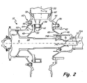
- FIG. 2 shows a cross-sectional view of blade pitch actuation mechanism 12 of FIG. 1 assembled with output shaft 42 and propeller hub 44.
- Blade pitch actuation mechanism 12 includes hydraulic actuator 46 (which comprises yoke 48, aft dome 49, forward dome 50 and hydraulic coupling 51), bearing support plate 52 and bearing assembly 54.
- Output shaft 42 which extends from gearbox 18 ( FIG. 1 ), is connected to propeller hub 44 and aft dome 49 at threaded fasteners 56, which typically comprises a bolt and nut.
- Propeller blade 20 is inserted into socket 58 and seated in bearing 60 such that trunnion pin 61 extends into socket 58.
- propeller blade 20 is free to rotate about axis X, while trunnion pin 61 is free to rotate around axis X.
- Propeller hub 44 is connected with forward dome 50 at threaded fastener 62, which also typically comprises a bolt and nut.
- Shaft 42, hub 44, aft dome 49 and forward dome 50 comprise annular bodies that are disposed concentrically around axis Y.
- Hub 44 is driven to rotate about axis Y by core engine 14, thus causing hub 44, aft dome 49 and forward dome 50 to also rotate about axis Y. Accordingly, propeller blade 20 is rotated about axis Y to react with the bypass air A B .
- Yoke 48 is disposed within hub 44 between forward dome 50 and aft dome 49.
- Flange 64 of yoke 48 is connected to bearing assembly 54, which is connected to bearing support plate 52 at threaded fastener 66, which typically comprises a bolt and nut or threaded hole.
- Bearing assembly 54 includes a bearing which receives trunnion pin 61 of propeller blade 20.
- Yoke 48 and hydraulic coupling 51 divide actuator 46 into first pressure chamber 68 and second pressure chamber 70, which are filled with hydraulic fluid such that they have pressures P1 and P2, respectively.
- pressures P1 and P2 are controlled by controlling the flow of hydraulic fluids into and out of chambers 68 and 70 through passage 72 or passage 72A. Seals 74A and 74B prevent hydraulic fluid from entering hub 44, while seal 74C seals between first pressure chamber 68 and second pressure chamber 70.
- yoke 48 translates along axis Y. Accordingly, feathering, unfeathering, speed governing, synchrophasing and beta control of propeller blades 20 is controlled.
- flange 64 actuates the rotation of trunnion pin 61 around axis X, thereby changing the pitch of propeller blade 20 as propeller blade 20 rotates about axis X in bearing 60.
- the rotation of trunnion pin 61 about axis X causes a rotation of yoke 48 about axis Y.
- Bearing assembly 54 is the final linkage between propeller blade 20 and actuation mechanism 12.
- bearing support plate 52 can be mounted within actuator 46 to provide a template for mounting bearing assembly 54 in either left-hand or right-hand configured engines.
- Bearing assembly 54 is also the transition point between trunnion pin 61, which tends to rotate about axis X as propeller blade 20 interacts with the bypass air A B , and flange 64 which tends to translate along axis Y as yoke 48 is actuated by valve 72.
- bearing assembly 54 is configured with means to reduce wear from and to transfer the forces applied by trunnion pin 61.
- bearing assembly 54 and bearing support plate 52 provide an easily assembled system for assembly and actuation of propeller blade 20.
- a plurality of bearing assemblies 54 are mounted in a unified pattern to bearing support plate 52 for receiving propeller blades 20.
- yoke 48 can be removed from hub 44 bringing along with it bearing assemblies 54.
- yoke 48 can be removed from hub 44 leaving bearing assemblies 54 connected with trunnion pins 61 and unified in assembly to bearing support plate 52.
- yoke 48 can be pre-assembled with bearing assemblies 54 mounted on bearing support plate 52 in the proper position such that upon insertion into hub 44 propeller blades 20 are readily inserted into sockets 58 with bearing assemblies 54 aligned for receiving trunnion pins 61.
- bearing assemblies 54 can be pre-assembled with trunnion pins 61 and then, after insertion of propeller blades 20 into sockets 58, assembled with bearing support plate 52.
- blade pitch actuation mechanism 12 is readily assembled or disassembled into sub-assemblies to facilitate maintenance or repair. For example, a hydraulic failure in actuator 46 can be addressed without the need for removing propeller blades 20 and bearing assemblies 54.
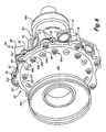
- FIG. 3 shows a perspective back view of one sub-assembly arrangement of actuation mechanism 12 that facilitates simplified assembly of a turboprop propeller assembly.
- Yoke 48 and hydraulic coupling 51 of actuator 46 are assembled with bearing support plate 52 and a plurality of bearing assemblies 54.
- Each bearing assembly 54 includes bearing 75, comprising slider block 76, outer race 77 and ball 78, and bearing support 80, which includes flanges 81.
- FIG. 3 shows bearing support plate 52 mounted to flange 64 of yoke 48 in a right-hand configuration such that bearing assemblies 54 receive trunnion pins 61 of right-hand configured propeller blades 20.
- bearing assemblies 54 receive trunnion pins 61 such that actuation of yoke 48 induces the proper rotation of propeller blades 20 within sockets 58 for a right-hand configured engine.
- bearing assemblies 54 are mountable to bearing support plate 52 in a left-hand configuration.
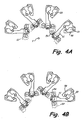
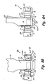
- FIG. 4A shows a front view of a simplified schematic of a plurality of propeller blades 20 mounted within sockets 58 of hub 44 and a plurality of trunnion pins 61 mounted within bearing assemblies 54 in a right-hand configuration.
- FIG. 4B shows a front view of a simplified schematic of a plurality of propeller blades 20 mounted within hubs 44 and a plurality of trunnion pins 61 mounted within bearing assemblies 54 in a left-hand configuration.
- Bearing assemblies 54 are mounted to support plate 52 (shown in phantom and oversized for clarity) such that they travel along axis Y when yoke 48 is actuated. Hubs 44 are, however, maintained stationary relative to axial movement along axis Y.
- Trunnion pins 61 are rotatable within bearing assemblies 54, and propeller blades 20 are rotatable within sockets 58. Thus, traversing of bearing assemblies along axis Y causes a rotation of propeller blades 20 within sockets 58.
- Trunnion pins 61 are connected with propeller blades 20 on opposite sides of sockets 58 for left-hand and right-hand configurations. As viewed from the front, trunnion pins 61 are connected to blades 20 on the left side of sockets 58 in FIG. 4A , and trunnion pins 61 are connected to blades 20 on the right side of sockets 58 in FIG. 4B . Accordingly, as can be seen in FIG. 4A , a movement of bearing assemblies 54 in the forward direction along axis Y (out of the plane of FIG.
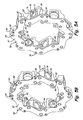
- FIG. 5A shows a perspective view of bearing assemblies 54 mounted to bearing support plate 52 of FIG. 3 in a right-hand configuration.
- FIG. 5B shows a perspective view of bearing assemblies 54 mounted to bearing support plate 52 of FIG. 3 in a left-hand configuration.
- Bearing support plate 52 includes ring shaped body 82, inner diameter 84, outer diameter 86, outer diameter flange 90, inner diameter holes 92 and outer diameter holes 94.
- Bearing assembly 54 includes slider block 76, outer race 77, ball 78 and bearing support 80, which includes flanges 81.
- FIG. 5B shows bearing support plate 52 of FIG. 5A rotated one hundred eighty degrees with respect to its fore and aft axis.
- bearing assemblies 54 can be mounted to bearing support plate in two configurations to receive trunnion pins 61 of propeller blades 20 arranged in left and right hand configurations.
- Ring-like shaped body 82 is shaped to follow the general contour of bearing assemblies 54.
- Bearing support 80 of bearing assemblies 54 are aligned to be generally perpendicular to the axis of trunnion pins 61 (as seen in FIGS. 4A and 4B ), which extend through and are allowed to rotate within ball 78.
- Inner diameter 84 and outer diameter 86 comprise multi-faceted surfaces that track the arrangement of bearing assemblies 54 in right-hand or left-hand arrangements.
- Body 82 thus only includes as little material as necessary to provide a buffer between bearing assemblies 54 and flange 64 of yoke 48, and to link each bearing assembly with one another.
- body 82 comprises a sacrificial layer between bearing assemblies 54 and yoke 48 that can be easily and inexpensively replaced, rather than replacing more costly components.
- Bearing support plate 82 provides temporary support of bearings support assemblies 54 prior to assembly of hydraulic actuator 46.
- Outer diameter holes 94 are arranged along the outer diameter 86 of body 82, and inner diameter holes 92 are arranged around inner diameter 84 of body 82.
- inner and outer diameter holes 92 and 94 align with holes in bearing supports 80.
- threaded fasteners 66 FIGS. 2 and 3
- bearing assemblies 54 are also directly secured to bearing support plate 52 to facilitate assembly and disassembly of blade pitch actuation mechanism 12.
- Bearing support plate 52 includes flanges 90 that align with flanges 81 of bearing support 80.
- Flanges 81 and flanges 90 include holes for receiving threaded fasteners 96, or some other such fastener.
- bearing assemblies 54 are securable to bearing support plate 52 such that yoke 48 can be inserted into hub 44 with bearing assemblies aligned for receiving trunnion pins 61.
- yoke 48 can be removed from within hub 44, while leaving bearing assemblies 54 secured to bearing support plate 52 and suspended on trunnion pins 61.
- Yoke 48 includes a bolt hole pattern that permits coupling with bearing support plate 52 in either the left-hand and right-hand configuration.
- FIG. 6 shows a perspective front view of blade pitch actuation mechanism 12 of FIG. 3 having bearing assembly yoke 48 with right-hand mounting holes 98A and left-hand mounting holes 98B.
- Yoke 48 includes outer diameter flange 64, inner diameter (or inboard) mounting holes 98A and 98B, outer diameter (or outboard) mounting holes 99.
- Yoke 48 is a conical forward yoke plate 101 that slopes from the forward end to the aft end of actuator 46 (as seen in FIG. 2 ) such that both forward and reverse loading transferred between trunnion pins 61 and actuator 46 are absorbed. Consequently, the need for an aft yoke plate to absorb forward and reverse loading is eliminated.
- Yoke 48 is connected to bearing support assembly 54 through bearing support plate 52 by threaded fasteners 66 and 104. Threaded fasteners 66 also secure bearing supports 80 of bearing support assemblies 54 to yoke 48. Bearing supports 80 are also independently secured to bearing support 80 through bearing support plate 52 and threaded fasteners 96, which are accommodated by flange 64 at notches 102. Outer diameter mounting holes 99 align with outer diameter holes 94 of bearing support plate 52. Thus, threaded fasteners used in threaded fastener 66 can be inserted through flange 64 and bearing support plate 52 and inserted into threaded holes of bearing support 80 of bearing support assembly 54. Only one set of outer diameter holes is necessary for mating with bearing support 80. Outer diameter holes 94 of bearing support plate 52 are alternatively used when bearing support plate 52 is in either the right-hand or left-hand configuration (e.g. flipped one hundred eighty degrees as shown in FIGS. 5A and 5B ).
- Inner diameter holes 92 shift along inner diameter 84 of body 82 when bearing support plate 52 is flipped from a right-hand to left-hand configuration, though remaining the same radial distance from axis Y. Accordingly, yoke 48 includes both left-hand mounting holes 98A and right-hand mounting holes 98B.
- FIG. 6 shows bearing support plate 52 and bearing assemblies 54 connected with flange 64 in a right-hand configuration. Accordingly, only right-hand mounting holes 98A of the inner diameter mounting holes are used, as is shown with threaded fasteners 104. However, when bearing support plate 52 is mounted to flange 64 in a left-hand configuration, e.g.
- bearing support plate 52 when bearing support plate 52 is flipped over, right-hand mounting holes 98A are not used and left-hand mounting holes 98B are used. As such, threaded fasteners 104 are shifted from holes 98A to holes 98B to align with holes in bearing supports 80. Additionally, when bearing assemblies 54 are locked down by threaded fasteners 66 and 104 with propeller blades 20 inserted into balls 78, yoke 48 assures that propeller blades 20 have a common blade angle through the connection of bearing assemblies 54 with trunnion pins 61. Bearing assemblies 54 also provide a heavy duty, wear resistant connection with trunnion pins 61.
- FIG. 7 shows an exploded view of bearing assembly 54, which comprises bearing support 80 and bearing 75.
- Bearing support includes first side leg 108, second side leg 110, end leg 112, bearing support bushings 114, bearing support pocket 116.
- Bearing 75 includes slider block 76, outer race 77, ball bearing 78, outer diameter lining 120 and ball bearing liner 121.
- Slider block 76 comprises a rectilinear or square outer surface to reduce contact stresses between bearing support 80, bearing support plate 52, and bearing 75.
- Bearing support 80 comprises a "U" shaped or horseshoe shaped bracket that straddles slider block 76.
- bearing support bears reverse loading from trunnion pins 61 and actuator 46, again eliminating the need for an aft yoke plate.
- Rectilinear slider block 76 distributes the loading from trunnion pin 61 to a larger amount of surface area on bearing support 80, as opposed to, for example, a cylindrical type outer race.
- Bearing 75 is inserted into pocket 116 such that bearing support 80 can be secured to bearing support plate 52 with bores 122 in bore portions 118. Bore portions 118 provide additional material flared from side legs 108 and 110 to accommodate threaded fasteners without adding excessive weight to bearing support 80.
- Bushings 114 are inserted into bores such that threaded fasteners 66 and 104 can be secured to support 80 after being inserted through yoke 54 and bearing support plate 52. Bushings 114 transfer rotational shear loads. Threaded fasteners are threaded into bearing support 80 to pre-load bearing support 80 against bearing support plate 52 and yoke 48.
- bearing support 80 is secured to bearing support plate 52 and yoke 48 with threaded fasteners 96 inserted into one of the bores 124 of flanges 81, depending on left or right hand assembly. Bores 124 are also provided with threaded holes to facilitate assembly with bearing support 80.
- bearing support 80 is effectively able to resist loads imparted by bearing 75 from trunnion pin 61. Bearing 75 is thus restrained from moving in five degrees of movement. However, bearing support 80 can be removed from around bearing 75 without the need for removing trunnion pin 61 from bearing 75 since, among other things, no aft yoke plate is present.
- Side legs 108 and 110, end leg 112 and slider block 76 are comprised of a hardened steel material.
- lining 120 is provided along the edges of slider block 76.
- Lining 120 comprises any high-wear material suitable for reducing the friction between bearing support 80 and slider block 76.
- Lining 120 can be secured to slider block 76, or alternatively, to pocket 116, in any suitable manner, such as with an adhesive, an epoxy or some other such bonding material.
- linings 118 and 120 are comprised of self-lubricating materials. Accordingly, the wear-life of bearing support 80 and slider block 76 are increased, and lining 120 can be easily and inexpensively replaced. Lining 120 also absorbs small dithering motions applied to bearing assembly 54 during operation of actuation mechanism 12 or from loading on propeller blades 20.
- FIG. 8A shows section A - A of FIG. 3 extending through bearing assembly 54 in the tangential direction.
- FIG. 8B shows section B - B of FIG. 3 extending through bearing assembly 54 in the axial direction.
- Slider block 76 is inserted into bearing support 80 such that bearing 75 can be connected to bearing support plate 52 and yoke 48.
- Slider block 76 includes a square-like or rectilinear outer diameter that inserts into a similarly shaped inner diameter within bearing support 80.
- Clearances 129 are provided between slider block 76 and bearing support 80 to accommodate machining and assembly tolerances. Clearances 129 are sized such that bearing assemblies can be easily assembled, but maintain tight linkage with trunnion pins 61.
- Slider block 76 includes a cylindrical or circular inner diameter for mating with outer race 77.
- Outer race 77 comprises a cylindrical or circular outer diameter that rides within the inner diameter of slider block 76.
- the inner diameter of outer race 77 comprises a spherical race that receives the spherical outer diameter of ball 78.
- Ball 78 includes a cylindrical or circular inner diameter bore with lining 121, similar to that of lining 120, to reduce friction and wear of pin 61 and for receiving trunnion pin 61.
- Outer race 77 includes lining 130, similar to that of lining 120, to reduce friction against and wear of ball 78 and to absorb dithering movements.
- Trunnion pin 61 includes bumper 132, which provides a sleeve of buffer material between trunnion pin 61 and the circular inner diameter of ball 78.
- Sleeve 132 comprises a material such as a hardened steel for wear resistance.
- Bumper 132A is a trunnion pin tip that is non-metallic, such as a hardened rubber, to provide a buffer to avoid damaging surfaces of bearing 75 during assembly, thus reducing the potential for creating burs or other friction increasing blemishes.
- the blade pitch actuation mechanism of the present invention provides a bearing mounting plate for mounting bearing assemblies to an actuator in either a left-hand or a right-hand configuration. Additionally, the bearing assemblies include wear linings and bumpers to increase the service life of the actuation mechanism. The bearing assemblies and the bearing support plate permit easy maintenance and assembly of the blade pitch actuation mechanism of the present invention.
Landscapes
- Engineering & Computer Science (AREA)
- Aviation & Aerospace Engineering (AREA)
- Structures Of Non-Positive Displacement Pumps (AREA)
- Support Of The Bearing (AREA)
Abstract
Description
- The present invention relates to blade pitch actuation mechanisms and in particular to actuator supported bearing assemblies for use in propeller blade pitch actuation mechanisms for turboprop engines.
- Turboprop engines are well suited to large payload capacity cargo planes due their high propulsive efficiency, i.e. their ability to turn power into usable thrust, which results in high fuel efficiency. Cargo planes typically require multiple engines to produce the power necessary to propel such large, heavily loaded aircraft. Many such multi-engine aircraft utilize opposite rotation turboprop engines, a right-hand (clockwise) rotating engine and a left-hand (counterclockwise) rotating engine on each wing, to reduce the turbulence effect of exit swirl and to reduce torque loads on wing structures.
- In a turboprop engine, a turbine is used to drive propeller blades for producing thrust. In a typical configuration, a spool comprising a compressor and a turbine is used to sustain a combustion process and produce hot gas for driving a free turbine. The free turbine, in turn, is used to drive a gearbox that rotates the propeller blades. In order to maintain engine efficiency during flight, turboprop engines are operated at a constant, peak-efficiency speed. Changes in engine power output are controlled by fuel flow and propeller blade pitch, which is controlled by a blade pitch actuation mechanism. Each propeller blade is typically connected to the blade pitch actuation mechanism through a trunnion pin and bearing assembly interface, which provides the force necessary to counter the rotational torque imparted to the propeller blade by the air stream and rotating forces generated by the mass distribution of the blade. The pitch of a propeller blade mounted on a right-hand engine is adjusted in the opposite direction as a blade mounted on a left-hand engine, thus necessitating differences in blade pitch actuation mechanism for left-hand and right-hand engines. It is, nonetheless, desirable to maintain interchangeability of parts for both right-hand and left-hand rotating engines to reduce time and expense in both production and maintenance of the engines. Additionally, the increased twisting moment about the pitch change axis of large propeller blades is translated to the blade pitch actuation mechanism. Thus, the bearing assembly surrounding the trunnion pin, which bears the reactive forces, is typically a high-wear component, especially as the size and thrust output of turboprop engines increase.
- There is, therefore, a need to increase the interchangeability of blade pitch actuation mechanisms for left-hand and right-hand configured engines. Additionally, there is a need for a wear-resistant and heavy-duty bearing assembly, as well as for a blade pitch actuation mechanism that permits easy maintenance and assembly.
- The present invention is directed toward a blade pitch actuation mechanism for a plurality of propeller blades supported in a blade hub. The blade pitch actuation mechanism comprises a plurality of bearing assemblies, a bearing support plate and a yoke. The bearing assemblies receive actuation trunnion pins from the plurality of propeller blades. The bearing support plate is connected to and unifies the plurality of bearing assemblies in a ring-like configuration. The yoke is connected to the bearing support plate and translates within the hub to adjust the pitch of the plurality of propeller blades.
- Certain preferred embodiments will now be described by way of example only and with reference to the accompanying drawings.
-
-
FIG. 1 shows a schematic view of a turboprop engine in which the blade pitch actuation mechanism of the present invention is used. -
FIG. 2 shows a cross-sectional view of a hydraulic actuation mechanism having the blade pitch actuation mechanism ofFIG. 1 . -
FIG. 3 shows a perspective back view of the blade pitch actuation mechanism ofFIG. 2 having a plurality of bearing assemblies connected to a bearing support plate. -
FIG. 4A shows a front view of a plurality of bearing assemblies mounted to the bearing support plate ofFIG. 3 in a right-hand configuration. -
FIG. 4B shows a front view of a plurality of bearing assemblies mounted to the bearing support plate ofFIG. 3 in a left-hand configuration. -
FIG. 5A shows a perspective view of the bearing assemblies ofFIG. 3 mounted to the bearing support plate in a right-hand configuration. -
FIG. 5B shows a perspective view of the bearing assemblies ofFIG. 3 mounted to the bearing support plate in a left-hand configuration. -
FIG. 6 shows a perspective front view of the blade pitch actuation mechanism ofFIG. 3 having a bearing assembly yoke with left-hand and right-hand mounting bores. -
FIG. 7 shows an exploded view of a bearing assembly comprising a bearing and a bearing support. -
FIG. 8A shows a cross section extending through a bearing assembly ofFIG. 3 in the tangential direction. -
FIG. 8B shows a cross section extending through a bearing assembly ofFIG. 3 in the axial direction. -
FIG. 1 shows a schematic side view ofturboprop engine 10 in which bladepitch actuation mechanism 12 of the present invention is used. Although the invention is hereinafter described with respect to a turboprop propeller system, the invention is also applicable to other systems such as tilt rotor and tilt wing systems. Turbopropengine 10 also includescore engine 14,inlet cowl 16,gearbox 18 andpropeller blades 20. Inlet air AI entersturboprop engine 10 throughinlet cowl 16 so that it can be used to sustain a combustion process withincore engine 14.Core engine 14 includescompressor 22,combustor section 24,core turbine 26 andfree turbine 28. Inlet air AI is compressed bycompressor 22 to supply a high-density mass of air tocombustor section 24. The mass of air is mixed with a fuel from injectors 30, whereby a combustion process is carried out to supply high-energy gas for turningcore turbine 26 andfree turbine 28. Inlet air AI, in the form of the high-energy gas, is thereafter routed out ofcore engine 14 andturboprop engine 10 atexit duct 32.Core turbine 26 turnscompressor 22 throughshaft 34 to sustain the supply of pressurized air tocombustor section 24.Free turbine 28 is not, however, connected withcompressor 22 and is therefore free to rotate at speeds dictated by the propellers. Throughshaft 36,free turbine 28 rotatespropeller blades 20 to react with bypass air AB to produce thrust. Thus, together with bladepitch actuation mechanism 12, the speed and pitch ofpropeller blades 20 can be adjusted to control the propulsive power generated byturboprop engine 10. - Shaft 36 extends from
free turbine 28, throughcore engine 14 andinlet cowl 16 togearbox 18. Gearbox 18 is supported withininlet cowl 16 byshaft sleeve 38 and supportstrut 40. Gearbox 18 reduces the rotational speed ofshaft 36 from the high speeds imparted byfree turbine 28 to the lower speeds necessary for rotating large-sizedpropeller blades 20. Gearbox 18 is also configured to produce either left-hand or right-hand rotation ofpropeller blades 20.Output shaft 42 ofgearbox 18 is connected topropeller hub 44, which drivespropeller blades 20. Bladepitch actuation mechanism 12 is situated withinhub 44 and is connected to inner diameter pitch actuation trunnion pins ofpropeller blades 20. Thus, in conjunction with a hydraulic actuator, the pitch ofpropeller blades 20 is adjusted to obtain the desired thrust output ofturboprop engine 10. Bladepitch actuation mechanism 12 provides interchangeable parts configurable for actuating both left-hand and right-hand configured propellers.Actuation mechanism 12 also provides wear resistant bearing assemblies for supporting large propeller blades. Furthermore,actuation mechanism 12 provides a simpler and more easily assembled and repairable actuation system. -
FIG. 2 shows a cross-sectional view of bladepitch actuation mechanism 12 ofFIG. 1 assembled withoutput shaft 42 andpropeller hub 44. Bladepitch actuation mechanism 12 includes hydraulic actuator 46 (which comprisesyoke 48,aft dome 49,forward dome 50 and hydraulic coupling 51), bearingsupport plate 52 and bearingassembly 54.Output shaft 42, which extends from gearbox 18 (FIG. 1 ), is connected topropeller hub 44 andaft dome 49 at threadedfasteners 56, which typically comprises a bolt and nut.Propeller blade 20 is inserted intosocket 58 and seated in bearing 60 such thattrunnion pin 61 extends intosocket 58. Thus,propeller blade 20 is free to rotate about axis X, whiletrunnion pin 61 is free to rotate around axis X.Propeller hub 44 is connected withforward dome 50 at threadedfastener 62, which also typically comprises a bolt and nut.Shaft 42,hub 44,aft dome 49 andforward dome 50 comprise annular bodies that are disposed concentrically around axis Y.Hub 44 is driven to rotate about axis Y bycore engine 14, thus causinghub 44,aft dome 49 andforward dome 50 to also rotate about axis Y. Accordingly,propeller blade 20 is rotated about axis Y to react with the bypass air AB. Yoke 48 is disposed withinhub 44 betweenforward dome 50 andaft dome 49.Flange 64 ofyoke 48 is connected to bearingassembly 54, which is connected to bearingsupport plate 52 at threadedfastener 66, which typically comprises a bolt and nut or threaded hole. Bearingassembly 54 includes a bearing which receivestrunnion pin 61 ofpropeller blade 20. -
Yoke 48 andhydraulic coupling 51 divide actuator 46 intofirst pressure chamber 68 andsecond pressure chamber 70, which are filled with hydraulic fluid such that they have pressures P1 and P2, respectively. Although simplified greatly for the purposes of this application, pressures P1 and P2 are controlled by controlling the flow of hydraulic fluids into and out ofchambers passage 72 orpassage 72A.Seals hub 44, whileseal 74C seals betweenfirst pressure chamber 68 andsecond pressure chamber 70. Thus, as pressures P1 and P2 are adjusted byvalve 72,yoke 48 translates along axis Y. Accordingly, feathering, unfeathering, speed governing, synchrophasing and beta control ofpropeller blades 20 is controlled. Asyoke 48 translates along axis Y,flange 64 actuates the rotation oftrunnion pin 61 around axis X, thereby changing the pitch ofpropeller blade 20 aspropeller blade 20 rotates about axis X in bearing 60. The rotation oftrunnion pin 61 about axis X causes a rotation ofyoke 48 about axis Y. - Bearing
assembly 54 is the final linkage betweenpropeller blade 20 andactuation mechanism 12. Thus, bearingsupport plate 52 can be mounted within actuator 46 to provide a template for mountingbearing assembly 54 in either left-hand or right-hand configured engines. Bearingassembly 54 is also the transition point betweentrunnion pin 61, which tends to rotate about axis X aspropeller blade 20 interacts with the bypass air AB, andflange 64 which tends to translate along axis Y asyoke 48 is actuated byvalve 72. Thus, bearingassembly 54 is configured with means to reduce wear from and to transfer the forces applied bytrunnion pin 61. - Together, bearing
assembly 54 and bearingsupport plate 52 provide an easily assembled system for assembly and actuation ofpropeller blade 20. For example, a plurality of bearingassemblies 54 are mounted in a unified pattern to bearingsupport plate 52 for receivingpropeller blades 20. As such, during disassembly, afterpropeller blades 20 are removed fromsockets 58 anddome 50 is removed fromhub 44,yoke 48 can be removed fromhub 44 bringing along with it bearingassemblies 54. Alternatively,yoke 48 can be removed fromhub 44 leavingbearing assemblies 54 connected with trunnion pins 61 and unified in assembly to bearingsupport plate 52. During assembly,yoke 48 can be pre-assembled with bearingassemblies 54 mounted on bearingsupport plate 52 in the proper position such that upon insertion intohub 44propeller blades 20 are readily inserted intosockets 58 with bearingassemblies 54 aligned for receiving trunnion pins 61. Alternatively, bearingassemblies 54 can be pre-assembled with trunnion pins 61 and then, after insertion ofpropeller blades 20 intosockets 58, assembled with bearingsupport plate 52. Thus, bladepitch actuation mechanism 12 is readily assembled or disassembled into sub-assemblies to facilitate maintenance or repair. For example, a hydraulic failure in actuator 46 can be addressed without the need for removingpropeller blades 20 andbearing assemblies 54. -
FIG. 3 shows a perspective back view of one sub-assembly arrangement ofactuation mechanism 12 that facilitates simplified assembly of a turboprop propeller assembly.Yoke 48 andhydraulic coupling 51 of actuator 46 are assembled with bearingsupport plate 52 and a plurality of bearingassemblies 54. Each bearingassembly 54, includes bearing 75, comprisingslider block 76,outer race 77 andball 78, and bearingsupport 80, which includesflanges 81.FIG. 3 shows bearingsupport plate 52 mounted to flange 64 ofyoke 48 in a right-hand configuration such that bearingassemblies 54 receivetrunnion pins 61 of right-hand configuredpropeller blades 20. More particularly, bearingassemblies 54 receivetrunnion pins 61 such that actuation ofyoke 48 induces the proper rotation ofpropeller blades 20 withinsockets 58 for a right-hand configured engine. However, bearingassemblies 54 are mountable to bearingsupport plate 52 in a left-hand configuration. -
FIG. 4A shows a front view of a simplified schematic of a plurality ofpropeller blades 20 mounted withinsockets 58 ofhub 44 and a plurality of trunnion pins 61 mounted within bearingassemblies 54 in a right-hand configuration.FIG. 4B shows a front view of a simplified schematic of a plurality ofpropeller blades 20 mounted withinhubs 44 and a plurality of trunnion pins 61 mounted within bearingassemblies 54 in a left-hand configuration.Bearing assemblies 54 are mounted to support plate 52 (shown in phantom and oversized for clarity) such that they travel along axis Y whenyoke 48 is actuated.Hubs 44 are, however, maintained stationary relative to axial movement along axis Y. Trunnion pins 61 are rotatable within bearingassemblies 54, andpropeller blades 20 are rotatable withinsockets 58. Thus, traversing of bearing assemblies along axis Y causes a rotation ofpropeller blades 20 withinsockets 58. - Trunnion pins 61 are connected with
propeller blades 20 on opposite sides ofsockets 58 for left-hand and right-hand configurations. As viewed from the front, trunnion pins 61 are connected toblades 20 on the left side ofsockets 58 inFIG. 4A , and trunnion pins 61 are connected toblades 20 on the right side ofsockets 58 inFIG. 4B . Accordingly, as can be seen inFIG. 4A , a movement of bearingassemblies 54 in the forward direction along axis Y (out of the plane ofFIG. 4A ), causes rotation ofpropeller blades 20 in a first direction (clockwise if viewed from the blade tip to the hub along axis X) for right-hand configured propeller blades. Conversely, as can be seen inFIG. 4B , a movement of bearingassemblies 54 in the forward direction along axis Y (out of the plane ofFIG. 4A ), causes rotation ofpropeller blades 20 in a second direction (counter-clockwise if viewed from the blade tip to the hub along axis X) for left-hand configured propeller blades. In order to achieve this configuration with the desired pitch actuation, it is necessary for bearingassemblies 54 to be canted with respect to axis Y in different directions. Bearingsupport plate 52 accommodates both configurations thus requiring manufacture of only a single component and thereby reducing manufacturing and maintenance costs. -
FIG. 5A shows a perspective view of bearingassemblies 54 mounted to bearingsupport plate 52 ofFIG. 3 in a right-hand configuration.FIG. 5B shows a perspective view of bearingassemblies 54 mounted to bearingsupport plate 52 ofFIG. 3 in a left-hand configuration. Bearingsupport plate 52 includes ring shapedbody 82,inner diameter 84,outer diameter 86,outer diameter flange 90, inner diameter holes 92 and outer diameter holes 94. Bearingassembly 54 includesslider block 76,outer race 77,ball 78 and bearingsupport 80, which includesflanges 81.FIG. 5B shows bearingsupport plate 52 ofFIG. 5A rotated one hundred eighty degrees with respect to its fore and aft axis. Accordingly, inner diameter holes 92 and outer diameter holes 94, as well as inner diameter flange 88 andouter diameter flange 90, realign from a right-handed configuration to a left-handed configuration. Thus, bearingassemblies 54 can be mounted to bearing support plate in two configurations to receivetrunnion pins 61 ofpropeller blades 20 arranged in left and right hand configurations. - Ring-like
shaped body 82 is shaped to follow the general contour of bearingassemblies 54. Bearingsupport 80 of bearingassemblies 54 are aligned to be generally perpendicular to the axis of trunnion pins 61 (as seen inFIGS. 4A and 4B ), which extend through and are allowed to rotate withinball 78.Inner diameter 84 andouter diameter 86 comprise multi-faceted surfaces that track the arrangement of bearingassemblies 54 in right-hand or left-hand arrangements.Body 82 thus only includes as little material as necessary to provide a buffer between bearingassemblies 54 andflange 64 ofyoke 48, and to link each bearing assembly with one another. Accordingly,body 82 comprises a sacrificial layer between bearingassemblies 54 andyoke 48 that can be easily and inexpensively replaced, rather than replacing more costly components. Bearingsupport plate 82 provides temporary support of bearings supportassemblies 54 prior to assembly of hydraulic actuator 46. Outer diameter holes 94 are arranged along theouter diameter 86 ofbody 82, and inner diameter holes 92 are arranged aroundinner diameter 84 ofbody 82. As such, inner and outer diameter holes 92 and 94 align with holes in bearing supports 80. Thus, threaded fasteners 66 (FIGS. 2 and3 ) are used to clamp bearing assembles 54 to flange 64 through bearingsupport plate 52. However, bearingassemblies 54 are also directly secured to bearingsupport plate 52 to facilitate assembly and disassembly of bladepitch actuation mechanism 12. - Bearing
support plate 52 includesflanges 90 that align withflanges 81 of bearingsupport 80.Flanges 81 andflanges 90 include holes for receiving threadedfasteners 96, or some other such fastener. Thus, bearingassemblies 54 are securable to bearingsupport plate 52 such thatyoke 48 can be inserted intohub 44 with bearing assemblies aligned for receiving trunnion pins 61. Conversely,yoke 48 can be removed from withinhub 44, while leavingbearing assemblies 54 secured to bearingsupport plate 52 and suspended on trunnion pins 61.Yoke 48 includes a bolt hole pattern that permits coupling with bearingsupport plate 52 in either the left-hand and right-hand configuration. -
FIG. 6 shows a perspective front view of bladepitch actuation mechanism 12 ofFIG. 3 havingbearing assembly yoke 48 with right-hand mounting holes 98A and left-hand mounting holes 98B.Yoke 48 includesouter diameter flange 64, inner diameter (or inboard) mountingholes Yoke 48 is a conicalforward yoke plate 101 that slopes from the forward end to the aft end of actuator 46 (as seen inFIG. 2 ) such that both forward and reverse loading transferred between trunnion pins 61 and actuator 46 are absorbed. Consequently, the need for an aft yoke plate to absorb forward and reverse loading is eliminated. -
Yoke 48 is connected to bearingsupport assembly 54 through bearingsupport plate 52 by threadedfasteners fasteners 66 also secure bearing supports 80 of bearingsupport assemblies 54 toyoke 48. Bearing supports 80 are also independently secured to bearingsupport 80 through bearingsupport plate 52 and threadedfasteners 96, which are accommodated byflange 64 atnotches 102. Outerdiameter mounting holes 99 align with outer diameter holes 94 of bearingsupport plate 52. Thus, threaded fasteners used in threadedfastener 66 can be inserted throughflange 64 and bearingsupport plate 52 and inserted into threaded holes of bearingsupport 80 of bearingsupport assembly 54. Only one set of outer diameter holes is necessary for mating with bearingsupport 80. Outer diameter holes 94 of bearingsupport plate 52 are alternatively used when bearingsupport plate 52 is in either the right-hand or left-hand configuration (e.g. flipped one hundred eighty degrees as shown inFIGS. 5A and 5B ). - Inner diameter holes 92 shift along
inner diameter 84 ofbody 82 when bearingsupport plate 52 is flipped from a right-hand to left-hand configuration, though remaining the same radial distance from axis Y. Accordingly,yoke 48 includes both left-hand mounting holes 98A and right-hand mounting holes 98B.FIG. 6 shows bearingsupport plate 52 andbearing assemblies 54 connected withflange 64 in a right-hand configuration. Accordingly, only right-hand mounting holes 98A of the inner diameter mounting holes are used, as is shown with threadedfasteners 104. However, when bearingsupport plate 52 is mounted toflange 64 in a left-hand configuration, e.g. when bearingsupport plate 52 is flipped over, right-hand mounting holes 98A are not used and left-hand mounting holes 98B are used. As such, threadedfasteners 104 are shifted fromholes 98A toholes 98B to align with holes in bearing supports 80. Additionally, when bearingassemblies 54 are locked down by threadedfasteners propeller blades 20 inserted intoballs 78,yoke 48 assures thatpropeller blades 20 have a common blade angle through the connection of bearingassemblies 54 with trunnion pins 61.Bearing assemblies 54 also provide a heavy duty, wear resistant connection with trunnion pins 61. -
FIG. 7 shows an exploded view of bearingassembly 54, which comprises bearingsupport 80 andbearing 75. Bearing support includesfirst side leg 108,second side leg 110,end leg 112, bearingsupport bushings 114, bearingsupport pocket 116.Bearing 75 includesslider block 76,outer race 77,ball bearing 78, outer diameter lining 120 andball bearing liner 121.Slider block 76 comprises a rectilinear or square outer surface to reduce contact stresses between bearingsupport 80, bearingsupport plate 52, andbearing 75. Bearingsupport 80 comprises a "U" shaped or horseshoe shaped bracket that straddlesslider block 76. Thus, bearing support bears reverse loading from trunnion pins 61 and actuator 46, again eliminating the need for an aft yoke plate.Rectilinear slider block 76 distributes the loading fromtrunnion pin 61 to a larger amount of surface area on bearingsupport 80, as opposed to, for example, a cylindrical type outer race. -
Bearing 75 is inserted intopocket 116 such that bearingsupport 80 can be secured to bearingsupport plate 52 withbores 122 inbore portions 118.Bore portions 118 provide additional material flared fromside legs support 80.Bushings 114 are inserted into bores such that threadedfasteners yoke 54 and bearingsupport plate 52.Bushings 114 transfer rotational shear loads. Threaded fasteners are threaded into bearingsupport 80 to pre-loadbearing support 80 against bearingsupport plate 52 andyoke 48. Thus, when forces from trunnion pins 61 attempt to separate bearingsupport 80 andsupport plate 52, the pre-load maintains the proper interface between bearingsupport 80 andsupport plate 52 to avoid tipping ofbearing 75.Bushings 114 also reduce wear on front surface of bearingsupport 80. Additionally, the portion ofbushings 114 that extend beyond bearingsupport 80 can be fitted intobores support plate 52 to locate bearingsupport 80 with respect to bearingsupport plate 52, thus maintaining tight tolerances and accommodating machining and assembly tolerances. Alternatively, bearingsupport 80 is secured to bearingsupport plate 52 andyoke 48 with threadedfasteners 96 inserted into one of thebores 124 offlanges 81, depending on left or right hand assembly.Bores 124 are also provided with threaded holes to facilitate assembly with bearingsupport 80. - When in
pocket 116, bearing 75 is effectively trapped between bearingsupport plate 52,side legs end leg 112.Top ridge 126 andbottom ridge 128 ofpocket 116 restrict motion of bearing 75 along the axis of trunnion pins 61, along axis X ofFIG. 2 . Bearingsupport plate 52 andend leg 112 restrict axial movement of bearing 75 along axis Y ofFIG. 2 .Side leg 108 andside leg 110 restrict side to side movement of bearing 108, movement tangent to axis Y inFIG. 2 . Thus, bearingsupport 80 is effectively able to resist loads imparted by bearing 75 fromtrunnion pin 61.Bearing 75 is thus restrained from moving in five degrees of movement. However, bearingsupport 80 can be removed from around bearing 75 without the need for removingtrunnion pin 61 from bearing 75 since, among other things, no aft yoke plate is present. -
Side legs end leg 112 andslider block 76 are comprised of a hardened steel material. In order to reduce friction and wear between bearingsupport 80 andslider block 76 of bearing 75, lining 120 is provided along the edges ofslider block 76. Lining 120 comprises any high-wear material suitable for reducing the friction between bearingsupport 80 andslider block 76. Lining 120 can be secured toslider block 76, or alternatively, to pocket 116, in any suitable manner, such as with an adhesive, an epoxy or some other such bonding material. In other embodiments,linings support 80 andslider block 76 are increased, and lining 120 can be easily and inexpensively replaced. Lining 120 also absorbs small dithering motions applied to bearingassembly 54 during operation ofactuation mechanism 12 or from loading onpropeller blades 20. -
FIG. 8A shows section A - A ofFIG. 3 extending through bearingassembly 54 in the tangential direction.FIG. 8B shows section B - B ofFIG. 3 extending through bearingassembly 54 in the axial direction.Slider block 76 is inserted into bearingsupport 80 such that bearing 75 can be connected to bearingsupport plate 52 andyoke 48.Slider block 76 includes a square-like or rectilinear outer diameter that inserts into a similarly shaped inner diameter within bearingsupport 80.Clearances 129 are provided betweenslider block 76 and bearingsupport 80 to accommodate machining and assembly tolerances.Clearances 129 are sized such that bearing assemblies can be easily assembled, but maintain tight linkage with trunnion pins 61.Slider block 76 includes a cylindrical or circular inner diameter for mating withouter race 77. -
Outer race 77 comprises a cylindrical or circular outer diameter that rides within the inner diameter ofslider block 76. The inner diameter ofouter race 77 comprises a spherical race that receives the spherical outer diameter ofball 78.Ball 78 includes a cylindrical or circular inner diameter bore with lining 121, similar to that of lining 120, to reduce friction and wear ofpin 61 and for receivingtrunnion pin 61.Outer race 77 includes lining 130, similar to that of lining 120, to reduce friction against and wear ofball 78 and to absorb dithering movements.Trunnion pin 61 includesbumper 132, which provides a sleeve of buffer material betweentrunnion pin 61 and the circular inner diameter ofball 78.Sleeve 132 comprises a material such as a hardened steel for wear resistance.Bumper 132A is a trunnion pin tip that is non-metallic, such as a hardened rubber, to provide a buffer to avoid damaging surfaces of bearing 75 during assembly, thus reducing the potential for creating burs or other friction increasing blemishes. - Therefore, the blade pitch actuation mechanism of the present invention provides a bearing mounting plate for mounting bearing assemblies to an actuator in either a left-hand or a right-hand configuration. Additionally, the bearing assemblies include wear linings and bumpers to increase the service life of the actuation mechanism. The bearing assemblies and the bearing support plate permit easy maintenance and assembly of the blade pitch actuation mechanism of the present invention.
- Although the present invention has been described with reference to preferred embodiments, workers skilled in the art will recognize that changes may be made in form and detail without departing from the scope of the invention which is defined by the following claims and their equivalents.
Claims (33)
- A blade pitch actuation mechanism (12) for a plurality of propeller blades (20) supported in a blade hub (44), the actuation mechanism (12) comprising:a plurality of bearing assemblies (54) for receiving a plurality of actuation trunnion pins (61) from the plurality of propeller blades (20);a bearing support plate (52) connected to the plurality of bearing assemblies (54) and unifying the plurality of bearing assemblies in a ring-like configuration; anda yoke (48) connected to the bearing support plate (52) and for translating within the blade hub (44) to adjust the pitch of the plurality of propeller blades (20).
- The blade pitch actuation mechanism (12) of claim 1 wherein the yoke (48) translates within a hydraulic actuator (46) disposed within the blade hub (44).
- The blade pitch actuation mechanism (12) of claim 1 or 2 wherein each of the bearing assemblies (54) comprising the plurality of bearing assemblies comprises:a bearing (75) comprising:a slider block (76) comprising:a rectilinear outer diameter; anda circular inner diameter; anda ball (78) comprising:an outer diameter for rotation in the circular inner diameter of the slider block (76) ; andan inner diameter for receiving an actuation trunnion pin (61);anda bearing support (80) for trapping the bearing (75) between the bearing support and the bearing support plate (52).
- The blade pitch actuation mechanism (12) of claim 3 wherein the bearing support (80) comprises a U-shaped structure.
- The blade pitch actuation mechanism (12) of claim 3 or 4 wherein each bearing assembly (54) further comprises wear material (120) positioned between outer diameter surfaces of the slider block (76) and inner diameter surfaces of the bearing support (80).
- The blade pitch actuation mechanism (12) of claim 3, 4 or 5 further comprising a replaceable sleeve (132) positioned within the inner diameter of the ball (78) and for receiving an actuation trunnion pin from the plurality of propeller blades (20).
- The blade pitch actuation mechanism (12) of any of claims 3 to 6, wherein each bearing support (80) includes clearance space between the outer diameter of the slider block (76), the bearing support plate (52), and the bearing support (80).
- The blade pitch actuation mechanism (12) of any of claims 3 to 6 wherein the three-sided bearing support (80) includes:first and second sides (108, 110) secured to the bearing support plate (52); anda third side (112) positioned between the first and second sides.
- The blade pitch actuation mechanism (12) of any preceding claim wherein the bearing support plate (52) includes a bolt hole (92, 96) for each bearing assembly (54) that are arranged such that the plurality of bearing assemblies (54) can be mounted to the bearing support plate (52) in a left-hand or a right-hand configuration.
- The blade pitch actuation mechanism (12) of claim 9 wherein the yoke (48) includes:a plurality of outer diameter bolt holes (99) for aligning with bolt holes (122) of the plurality of bearing assemblies (54) in both the left-hand and right-hand configuration;a first plurality of inner diameter bolt holes (98B) for aligning with bolt holes (122) of the plurality of bearing assemblies (54) in the left-hand configuration; anda second plurality of inner diameter bolt holes (98A) for aligning with bolt holes (122) of the plurality of bearing assemblies (54) in the right-hand configuration.
- The blade pitch actuation mechanism (12) of claim 9 or 10 wherein the bearing support plate (52) comprises a ring-like shape having multi-faceted inner and outer diameters (84, 86) that track the arrangement of the plurality of bearing assemblies (54) in either the left-hand or right-hand configuration.
- The blade pitch actuation mechanism (12) of claim 11 wherein:the bearing support plate (52) further includes a plurality of first bolt-hole flanges (90); andeach of the bearing assemblies (54) further includes a second bolt-hole flange (81) for aligning with one of the plurality of first bolt-hole flanges (90) such that each bearing assembly (54) is securable to the bearing support plate (52) outside the ring-like shape of the bearing support plate (52).
- The blade pitch actuation mechanism (12) of claim 12 wherein the plurality of first bolt-hole flanges (90) extend from the outer diameters of the bearing support plate (52).
- The blade pitch actuation mechanism (12) of any preceding claim wherein the yoke (48) comprises a forward yoke plate (101) having a profile sloped from the forward edge to the aft edge.
- A blade pitch actuation mechanism (12) comprising:a bearing (75) comprising:a rectilinear slider block (76); andan inner diameter ball (78) riding in the slider block (76) and for receiving a trunnion pin (61) from a propeller blade (20);a three-sided bearing retainer (80) for surrounding the rectilinear outer race (77); anda bearing support plate (52) connected to the three-sided bearing retainer (80) for trapping the rectilinear slider block (76) within the three-sided retainer (80).
- The blade pitch actuation mechanism (12) of claim 15 wherein the bearing support plate (52) is configured for mounting to a yoke (48) of a propeller blade actuator such that the bearing support plate (52) provides a buffer between the yoke (48), the three-sided bearing retainer (80) and the rectilinear slider block (76).
- The blade pitch actuation mechanism (12) of claim 15 or 16 wherein the three-sided bearing support (80) includes bore portions (122) for receiving means for mounting the three-sided bearing retainer (80) to the yoke (48).
- The blade pitch actuation mechanism (12) of claim 17 wherein the bore portions (122) include bore bushings (114) for receiving the mounting means and for aligning the bearing support plate (52).
- The blade pitch actuation mechanism (12) of any of claims 15 to 19 further comprising wear material (120) positioned between the rectilinear slider block (76) and the three-sided bearing retainer (80) and the bearing support plate (52).
- The blade pitch actuation mechanism (12) of any of claims 15 to 19 further comprising a bumper (132) positioned at the end of the trunnion pin (61) to protect a liner (121) within the ball inner diameter.
- The blade pitch actuation mechanism (12) of any of claims 15 to 20 further comprising an outer race (77) between the slider block (76) and the ball (78), and wear material (130) positioned between the outer race (77) and the inner diameter ball (78).
- The blade pitch actuation mechanism (12) of any of claims 15 to 21 wherein the three-sided bearing retainer (80) includes a pocket such that movement of the rectilinear slider block (75) is restrained in five degrees of movement.
- The blade pitch actuation mechanism (12) of any of claims 15 to 22 wherein a perimeter provided by the three-sided bearing support (80) and the bearing support plate (52) is larger than an outer diameter of the rectilinear slider block (75).
- The blade pitch actuation mechanism (12) of any of claims 15 to 23 wherein the bearing support plate (52) further comprises:a body having a ring-like geometry;multi-faceted inner and outer diameters (84, 86) that track an arrangement of the plurality of bearing assemblies (54) in either the left-hand or right-hand configuration; anda set of bolt holes (92, 94) for each bearing assembly (54) between the multi-faceted inner and outer diameters (84, 86) that are arranged such that the plurality of bearing assemblies (54) can be mounted to the bearing support plate (52) in a left-hand or a right-hand configuration
- The blade pitch actuation mechanism (12) of claim 24 wherein:the bearing support plate (52) further includes a first bolt-hole flange (90) extending beyond the perimeter of the body; andthe three-sided bearing retainer (80) further includes a second bolt-hole flange (81) aligned with the first bolt-hole flange (90).
- A blade pitch actuation mechanism (12) comprising:a plurality of bearing assemblies (54) for receiving a plurality of actuation pin trunnions (61) from a plurality of propeller blades (20); anda bearing support plate (52) configured for jointly connecting the plurality of bearing assemblies (54) in either a left-hand or a right-hand orientation, the bearing support plate (52) comprising:a body having a ring-like geometry;multi-faceted inner and outer diameters (84, 84) that track the arrangement of the plurality of bearing assemblies (154) in either the left-hand or right-hand orientation; anda set of bolt holes (92, 94) for each bearing assembly (54) that are positioned between the multi-faceted inner and outer diameters (84, 86) that are arranged such that the plurality of bearing assemblies (54) can be mounted to the bearing support plate (52) in either the left-hand or a right-hand orientation.
- The blade pitch actuation mechanism (12) of claim 26 and further comprising a yoke (48) for translating within the blade pitch actuation mechanism (12) to adjust the axial position of the plurality of bearing assemblies (54), the yoke (48) comprising a set of bolt holes (98a, 98b, 99) for receiving the plurality of bearing assemblies (54) in either the left-hand or right-hand orientation.
- The blade pitch actuation mechanism (12) of claim 27 wherein the yoke (48) includes a forward yoke plate (101) having a profile slanted from the leading edge to the trailing edge for bearing forward and reverse loads of the bearing during translation within a hub (44).
- The blade pitch actuation mechanism (12) of claim 27 or 28 wherein the bearing support plate (54) provides a buffer between the yoke (48), the three-sided bearing retainer (80) and the plurality of bearing assemblies (54).
- The blade pitch actuation mechanism (12) of claim 27, 28 or 29 wherein the set of bolt holes (98A, 98B, 99) comprises:a set of outer diameter bolt holes (99) for aligning with bolt holes (122) of the plurality of bearing assemblies (54) in both the left-hand and right-hand orientation;a first set of inner diameter bolt holes (98B) for aligning with bolt holes (122) of the plurality of bearing assemblies (54) in the left-hand orientation; anda second set of inner diameter bolt holes (98A) for aligning with bolt holes (122) of the plurality of bearing assemblies (54) in the right-hand orientation.
- The blade pitch actuation mechanism (12) of any of claims 26 to 30 wherein:the bearing support plate (52) further includes a plurality of first bolt-hole flanges (90) extending outside the ring-like geometry of the body; andeach of the bearing assemblies (54) further includes a second bolt-hole flange (81) for aligning with one of the plurality of first bolt-hole flanges (90) such that each bearing assembly (54) is securable to the bearing support plate (52).
- The blade pitch actuation mechanism (12) of claim 31 wherein the plurality of first bolt-hole flanges (90) extend from the outer diameters of the bearing support plate (54).
- The blade pitch actuation mechanism (12) of any of claims 26 to 32 further comprising bushings (114) positioned within the plurality of bearing assemblies (54) aligned with bores (92) in the bearing support plate (52).
Applications Claiming Priority (1)
| Application Number | Priority Date | Filing Date | Title |
|---|---|---|---|
| US11/811,491 US7976279B2 (en) | 2007-06-11 | 2007-06-11 | Blade pitch actuation mechanism |
Publications (3)
| Publication Number | Publication Date |
|---|---|
| EP2003055A2 true EP2003055A2 (en) | 2008-12-17 |
| EP2003055A3 EP2003055A3 (en) | 2012-05-30 |
| EP2003055B1 EP2003055B1 (en) | 2014-01-08 |
Family
ID=39798174
Family Applications (1)
| Application Number | Title | Priority Date | Filing Date |
|---|---|---|---|
| EP08251245.0A Active EP2003055B1 (en) | 2007-06-11 | 2008-03-31 | Blade pitch actuation mechanism |
Country Status (3)
| Country | Link |
|---|---|
| US (1) | US7976279B2 (en) |
| EP (1) | EP2003055B1 (en) |
| ES (1) | ES2445188T3 (en) |
Cited By (2)
| Publication number | Priority date | Publication date | Assignee | Title |
|---|---|---|---|---|
| GB2461801A (en) * | 2008-07-14 | 2010-01-20 | Hamilton Sundstrand Corp | Integrated actuator for a propeller system |
| EP3219609A1 (en) * | 2016-03-18 | 2017-09-20 | Hamilton Sundstrand Corporation | Propeller pitch change actuation system |
Families Citing this family (9)
| Publication number | Priority date | Publication date | Assignee | Title |
|---|---|---|---|---|
| US8439640B2 (en) * | 2008-07-15 | 2013-05-14 | Hamilton Sundstrand Corporation | Propeller blade pitch control system |
| EP2386756A4 (en) * | 2008-12-19 | 2013-06-26 | Mitsubishi Heavy Ind Ltd | Pitch drive apparatus for wind power generating apparatus and wind power generating apparatus |
| US9120559B2 (en) | 2012-04-18 | 2015-09-01 | Hamilton Sundstrand Corporation | Propeller blade pitch actuation system |
| PL226825B1 (en) | 2015-09-07 | 2017-09-29 | Gen Electric | Method and system for an airscrew pitch adjustment |
| US10221706B2 (en) | 2015-11-17 | 2019-03-05 | General Electric Company | Variable pitch fan actuator |
| EP3241743B1 (en) * | 2016-05-02 | 2018-12-26 | Ratier-Figeac SAS | Blade pitch control |
| CN106838262A (en) * | 2016-11-30 | 2017-06-13 | 无锡明珠增压器制造有限公司 | The transmission mechanism of propeller pump dynamograph |
| CN109278985B (en) * | 2018-11-20 | 2023-09-29 | 西安君晖航空科技有限公司 | A pitch device and its installation method |
| US12565855B1 (en) | 2025-02-14 | 2026-03-03 | General Electric Company | Gas turbine engine |
Citations (1)
| Publication number | Priority date | Publication date | Assignee | Title |
|---|---|---|---|---|
| EP1775213A2 (en) | 2005-10-12 | 2007-04-18 | Hamilton Sundstrand Corporation | Propeller pitch change system |
Family Cites Families (10)
| Publication number | Priority date | Publication date | Assignee | Title |
|---|---|---|---|---|
| US4817382A (en) * | 1985-12-31 | 1989-04-04 | The Boeing Company | Turboprop propulsion apparatus |
| US4738591A (en) * | 1986-09-09 | 1988-04-19 | General Electric Company | Blade pitch varying mechanism |
| DE3710321C1 (en) * | 1987-03-28 | 1988-06-01 | Mtu Muenchen Gmbh | Fan blade, especially for prop fan engines |
| US5364231A (en) * | 1992-12-22 | 1994-11-15 | Alliedsignal Inc. | Full authority propeller pitch control |
| US5961067A (en) * | 1996-09-10 | 1999-10-05 | Allison Engine Company | Method for reducing turboprop noise |
| US6015264A (en) * | 1997-08-15 | 2000-01-18 | United Technologies Corporation | Preloaded retention assembly for aircraft propeller blade retention |
| US5836743A (en) * | 1997-10-22 | 1998-11-17 | United Technologies Corporation | Variable pitch counterweighted propeller system with releasable hydraulic pitchlock |
| US6077040A (en) * | 1998-05-01 | 2000-06-20 | United Technologies Corporation | Control system for blades for a variable pitch propeller |
| US6280142B1 (en) * | 1999-12-20 | 2001-08-28 | United Technologies Corporation | Pressure relief device for a propeller hub |
| US6514044B2 (en) * | 2000-12-21 | 2003-02-04 | Hamilton Sundstrand Corporation | Offset crowned roller assembly for variable pitch propellers |
-
2007
- 2007-06-11 US US11/811,491 patent/US7976279B2/en active Active
-
2008
- 2008-03-31 EP EP08251245.0A patent/EP2003055B1/en active Active
- 2008-03-31 ES ES08251245.0T patent/ES2445188T3/en active Active
Patent Citations (1)
| Publication number | Priority date | Publication date | Assignee | Title |
|---|---|---|---|---|
| EP1775213A2 (en) | 2005-10-12 | 2007-04-18 | Hamilton Sundstrand Corporation | Propeller pitch change system |
Cited By (5)
| Publication number | Priority date | Publication date | Assignee | Title |
|---|---|---|---|---|
| GB2461801A (en) * | 2008-07-14 | 2010-01-20 | Hamilton Sundstrand Corp | Integrated actuator for a propeller system |
| GB2461801B (en) * | 2008-07-14 | 2010-11-10 | Hamilton Sundstrand Corp | Integrated actuator for a propeller system |
| US8133027B2 (en) | 2008-07-14 | 2012-03-13 | Hamilton Sundstrand Corporation | Integrated actuator for a propeller system |
| EP3219609A1 (en) * | 2016-03-18 | 2017-09-20 | Hamilton Sundstrand Corporation | Propeller pitch change actuation system |
| US10077103B2 (en) | 2016-03-18 | 2018-09-18 | Hamilton Sundstrand Corporation | Propeller pitch change actuation system |
Also Published As
| Publication number | Publication date |
|---|---|
| EP2003055B1 (en) | 2014-01-08 |
| ES2445188T3 (en) | 2014-02-28 |
| EP2003055A3 (en) | 2012-05-30 |
| US20100021304A1 (en) | 2010-01-28 |
| US7976279B2 (en) | 2011-07-12 |
Similar Documents
| Publication | Publication Date | Title |
|---|---|---|
| EP2003055B1 (en) | Blade pitch actuation mechanism | |
| US9849970B2 (en) | Turbo engine with propeller(s) for an aircraft with a system for changing the pitch of the propeller | |
| US12110846B2 (en) | Mechanically-distributed propulsion drivetrain and architecture | |
| CN118382580A (en) | Turbine module equipped with pitch-variable blades and oil delivery means | |
| EP2538036B1 (en) | Integral bearing support and centering spring assembly for a gas turbine engine | |
| US7296969B2 (en) | Propeller pitch change system | |
| US10766603B2 (en) | Pitch-change system equipped with means for adjusting blade pitch and corresponding turbine engine | |
| US10604235B2 (en) | Pitch change module for turbine engine and corresponding turbine engine | |
| US11149741B2 (en) | Variable pitch fan for a gas turbine engine | |
| EP0092345B1 (en) | Vectorable nozzles for turbomachines | |
| US11725592B2 (en) | Aeronautical propulsion system having a low leakage flow rate and improved propulsion efficiency | |
| EP2525046B1 (en) | Propulsion engine | |
| US12358635B2 (en) | Inlet assembly | |
| JP2016130509A (en) | Thrust generating device | |
| WO2015105202A1 (en) | Thrust generation device | |
| CN116745206B (en) | Variable pitch fan | |
| US12202596B2 (en) | Aerodynamic rotary interface | |
| JPWO2015105202A1 (en) | Thrust generator | |
| CN222010812U (en) | A piston engine brake device for unmanned aerial vehicle | |
| JP2024015642A (en) | Thrust generation device |
Legal Events
| Date | Code | Title | Description |
|---|---|---|---|
| PUAI | Public reference made under article 153(3) epc to a published international application that has entered the european phase |
Free format text: ORIGINAL CODE: 0009012 |
|
| AK | Designated contracting states |
Kind code of ref document: A2 Designated state(s): AT BE BG CH CY CZ DE DK EE ES FI FR GB GR HR HU IE IS IT LI LT LU LV MC MT NL NO PL PT RO SE SI SK TR |
|
| AX | Request for extension of the european patent |
Extension state: AL BA MK RS |
|
| PUAL | Search report despatched |
Free format text: ORIGINAL CODE: 0009013 |
|
| AK | Designated contracting states |
Kind code of ref document: A3 Designated state(s): AT BE BG CH CY CZ DE DK EE ES FI FR GB GR HR HU IE IS IT LI LT LU LV MC MT NL NO PL PT RO SE SI SK TR |
|
| AX | Request for extension of the european patent |
Extension state: AL BA MK RS |
|
| RIC1 | Information provided on ipc code assigned before grant |
Ipc: B64C 11/38 20060101ALI20120425BHEP Ipc: B64C 11/30 20060101AFI20120425BHEP |
|
| 17P | Request for examination filed |
Effective date: 20121130 |
|
| AKX | Designation fees paid |
Designated state(s): DE ES FR GB IT |
|
| GRAP | Despatch of communication of intention to grant a patent |
Free format text: ORIGINAL CODE: EPIDOSNIGR1 |
|
| INTG | Intention to grant announced |
Effective date: 20130409 |
|
| RIN1 | Information on inventor provided before grant (corrected) |
Inventor name: RAES, MARK Inventor name: CARVALHO, PAUL A. |
|
| GRAP | Despatch of communication of intention to grant a patent |
Free format text: ORIGINAL CODE: EPIDOSNIGR1 |
|
| INTG | Intention to grant announced |
Effective date: 20130531 |
|
| GRAS | Grant fee paid |
Free format text: ORIGINAL CODE: EPIDOSNIGR3 |
|
| GRAA | (expected) grant |
Free format text: ORIGINAL CODE: 0009210 |
|
| AK | Designated contracting states |
Kind code of ref document: B1 Designated state(s): DE ES FR GB IT |
|
| REG | Reference to a national code |
Ref country code: GB Ref legal event code: FG4D |
|
| REG | Reference to a national code |
Ref country code: DE Ref legal event code: R096 Ref document number: 602008029743 Country of ref document: DE Effective date: 20140220 |
|
| REG | Reference to a national code |
Ref country code: ES Ref legal event code: FG2A Ref document number: 2445188 Country of ref document: ES Kind code of ref document: T3 Effective date: 20140228 |
|
| REG | Reference to a national code |
Ref country code: DE Ref legal event code: R097 Ref document number: 602008029743 Country of ref document: DE |
|
| PLBE | No opposition filed within time limit |
Free format text: ORIGINAL CODE: 0009261 |
|
| STAA | Information on the status of an ep patent application or granted ep patent |
Free format text: STATUS: NO OPPOSITION FILED WITHIN TIME LIMIT |
|
| 26N | No opposition filed |
Effective date: 20141009 |
|
| REG | Reference to a national code |
Ref country code: DE Ref legal event code: R097 Ref document number: 602008029743 Country of ref document: DE Effective date: 20141009 |
|
| REG | Reference to a national code |
Ref country code: FR Ref legal event code: PLFP Year of fee payment: 9 |
|
| REG | Reference to a national code |
Ref country code: FR Ref legal event code: PLFP Year of fee payment: 10 |
|
| REG | Reference to a national code |
Ref country code: DE Ref legal event code: R082 Ref document number: 602008029743 Country of ref document: DE Representative=s name: SCHMITT-NILSON SCHRAUD WAIBEL WOHLFROM PATENTA, DE |
|
| REG | Reference to a national code |
Ref country code: FR Ref legal event code: PLFP Year of fee payment: 11 |
|
| P01 | Opt-out of the competence of the unified patent court (upc) registered |
Effective date: 20230522 |
|
| PGFP | Annual fee paid to national office [announced via postgrant information from national office to epo] |
Ref country code: ES Payment date: 20250401 Year of fee payment: 18 |
|
| PGFP | Annual fee paid to national office [announced via postgrant information from national office to epo] |
Ref country code: GB Payment date: 20260220 Year of fee payment: 19 |
|
| PGFP | Annual fee paid to national office [announced via postgrant information from national office to epo] |
Ref country code: DE Payment date: 20260219 Year of fee payment: 19 |
|
| PGFP | Annual fee paid to national office [announced via postgrant information from national office to epo] |
Ref country code: IT Payment date: 20260219 Year of fee payment: 19 |
|
| PGFP | Annual fee paid to national office [announced via postgrant information from national office to epo] |
Ref country code: FR Payment date: 20260220 Year of fee payment: 19 |