EP2002937A1 - Profile lifter for a nailer - Google Patents
Profile lifter for a nailer Download PDFInfo
- Publication number
- EP2002937A1 EP2002937A1 EP08158067A EP08158067A EP2002937A1 EP 2002937 A1 EP2002937 A1 EP 2002937A1 EP 08158067 A EP08158067 A EP 08158067A EP 08158067 A EP08158067 A EP 08158067A EP 2002937 A1 EP2002937 A1 EP 2002937A1
- Authority
- EP
- European Patent Office
- Prior art keywords
- driver
- flywheel
- frame
- driving tool
- pinch roller
- Prior art date
- Legal status (The legal status is an assumption and is not a legal conclusion. Google has not performed a legal analysis and makes no representation as to the accuracy of the status listed.)
- Granted
Links
Images



Classifications
-
- B—PERFORMING OPERATIONS; TRANSPORTING
- B25—HAND TOOLS; PORTABLE POWER-DRIVEN TOOLS; MANIPULATORS
- B25C—HAND-HELD NAILING OR STAPLING TOOLS; MANUALLY OPERATED PORTABLE STAPLING TOOLS
- B25C1/00—Hand-held nailing tools; Nail feeding devices
- B25C1/06—Hand-held nailing tools; Nail feeding devices operated by electric power
Definitions
- the present invention generally relates to driving tools, such as nailers. More particularly to a driving tool having a driver that is selectively translated by a rotating flywheel and a method for operating a driving tool.
- U.S. Patent No. 7,204,403 B2 discloses a driving tool having a driver that is selectively translated by a rotating flywheel.
- a pair of resilient return cords biases the driver into a returned position relative to a structural backbone or frame.
- the upper bumper assembly is configured to abut a contoured end face of the driver; the shapes of the contoured end face and an abutting surface of the upper bumper assembly cooperate to impede movement of the end of the driver associated with the contoured end face in a direction toward the flywheel.
- the present teachings provide a driving tool that includes a frame, a motor assembly and a resilient member.
- the motor assembly is coupled to the frame and includes an electric motor, a flywheel driven by the electric motor, a pinch roller and a driver disposed between the flywheel and the pinch roller.
- the pinch roller is selectively movable from a first position to a second position to drive the driver into engagement with the flywheel.
- the driver is movable between a returned position and an extended position.
- the resilient member is coupled to the frame and biases the driver away from the flywheel to reduce or eliminate contact between the flywheel and the driver when the flywheel is at rest, the driver is in the returned position and the pinch roller is in the first position.
- the present teachings provide a method of operating a driver.
- the method can include: providing a driver that includes a frame and a motor assembly, the motor assembly being coupled to the frame and including an electric motor, a flywheel driven by the electric motor, a pinch roller and a driver disposed between the flywheel and the pinch roller, the pinch roller being selectively movable from a first position to a second position to drive the driver into engagement with the flywheel, the driver being movable between a returned position and an extended position; and supporting the driver on opposite lateral side of the flywheel when the flywheel is at rest, the driver is in the returned position and the pinch roller is in the first position.
- the present teachings provide a driving tool that includes a frame, a motor assembly and a support.
- the motor assembly is coupled to the frame and includes a flywheel and a driver.
- the flywheel is rotatable about a rotational axis.
- the driver is selectively translated by the flywheel from a returned position to an extended position.
- the support is coupled to the frame and includes at least one movable portion that contacts the driver when the driver is in the returned position and the flywheel is at rest, the at least one movable portion urging the driver in a direction away from the flywheel.
- the support preferably includes a support body and the at least one movable portion of the support preferably is resiliently coupled to the support body.
- the support body is clipped to the frame.
- the at least one movable portion may include a spring, for example a leaf spring.
- the support includes a first portion on a first lateral side of the flywheel and a second portion on a second lateral side of the flywheel.
- the support is generally U-shaped.
- a driving tool constructed in accordance with the teachings of the present invention is generally indicated by reference numeral 10.
- the fastening tool 10 can include a housing assembly 12, a backbone or frame 14, a backbone cover 16, a drive motor assembly 18, a control unit 20, a nosepiece assembly 22, a magazine assembly 24, a battery pack 26 and a support 28 ( Fig. 5 ). While the fastening tool 10 is illustrated as being electrically powered by a suitable power source, such as the battery pack 26, those skilled in the art will appreciate that the invention, in its broader aspects, may be constructed somewhat differently and that aspects of the present invention may have applicability to pneumatically powered fastening tools.
- the drive motor assembly 18 may also be employed in various other mechanisms that utilize reciprocating motion, including rotary hammers, hole forming tools, such as punches, and riveting tools, such as those that install deformation rivets.
- the housing assembly 12, the frame 14, the backbone cover 16, the drive motor assembly 18, the control unit 20, the nosepiece assembly 22, the magazine assembly 24 and the battery pack 26 can be constructed in a manner which is described in U.S. Patent Application No. 11/095,723 entitled “Method For Controlling A Power Driver” and U.S. Patent Application No. 11/095,696 entitled “Activation Arm Configuration For A Power Tool", the disclosures of which are hereby incorporated by reference as if fully set forth in detail herein.
- the housing 12 can shroud all or portions of the frame 14, the drive motor assembly 18 and the control unit 20.
- the frame 14 can serve as a structure or foundation to which the backbone cover 16, the drive motor assembly 18 the control unit 20 and the nosepiece assembly 22 can be coupled.
- the drive motor assembly 18 can include a power source 30, a driver 32, a follower assembly 34, which can include a follower 50, such as a roller, and a return mechanism 36.
- the power source 30 can include a motor 40, a flywheel 42 and an actuator 44.
- the flywheel 42 can be driven by the motor 40 for example via a motor pulley 254, which can be coupled for rotation with an output member of the motor 40, a flywheel pulley 300, which can be rotatably coupled to the flywheel 42, and a belt 280 that can transmit rotary power from the motor pulley 254 to the flywheel pulley 300.
- the actuator 44 can be employed to move the follower assembly 34 to drive the roller 50 toward the flywheel 42.
- the driver 32 can be disposed between the flywheel 42 and the roller 50 and can include an upper driver member 500 and a driver blade 502.
- the upper driver member 500 can include a body 510 and a pair of projections 512 that extend from the opposite lateral sides of the body 510.
- the body 510 may include a driver profile 520 ( Fig. 7 ), which is configured to engage the exterior surface 350 of the flywheel 42, and a cam profile 522 that is disposed on a side of the body 510 opposite the driver profile 520 ( Fig. 7 ).
- the projections 512 can be employed both as return anchors 630, i.e., points at which the driver 32 is coupled to the return mechanism 36 ( Fig. 2 ), and as bumper tabs 632 that are used to stop downward movement of the driver 32 after a fastener has been installed to a workpiece.
- the return mechanism 36 can include a housing 1050, which can be coupled to the frame 14, and a pair of return cords 1052 that can be engaged to the housing 1050 and the projections 512.
- the return cords 1052 can be resilient to permit the driver 32 to translate between a returned position and an extended position along a translation axis 118; the return cords 1052 can bias the driver 32 toward the returned position.
- the support 28 can include a body portion 1000 and a support portion 1002.
- the body portion 1000 and the support portion 1002 are unitarily formed of spring steel.
- the body portion can be coupled or secured to the frame 14 in any desired manner, such as threaded fasteners (not shown).
- the body portion 1000 can include a span member 1008 that can span the width of the frame 14 at a location forwardly of the flywheel 42 as well as first and second clip structures 1010 and 1012, respectively, that can be removably coupled to the opposite lateral sides of the frame 14.
- the first clip structure 1010 can be coupled to a first side of the span member 1008 and can be a generally C-shaped bracket configured to engage a rail 1014 ( Fig.
- the second clip structure 1012 can include a tab 1016 that can be resiliently coupled to a second, opposite side of the span member 1008.
- the tab 1016 can include an opening 1018 that can receive a projection 1020 formed on the frame 14 when the body portion 1000 is engaged to the frame 14.
- the first clip structure 1010 can be aligned to the rail 1014 ( Fig. 7 ) and the body portion 1000 can be rotated about the rail 1014 ( Fig. 7 ) to cause the tab 1016 to slip over the projection 1020 to align the opening 1018 to the projection 1020.
- the resilient configuration of the tab 1016 secures the body portion 1000 to the frame 14, while the opening 1018 and the first clip structure 1010 cooperate with the projection 1020 and the rail 1014 ( Fig. 7 ), respectively, to prevent the body portion 1000 from slipping off the frame 14.
- the support portion 1002 can be coupled to the body portion 1000 and can be configured in any desired manner to support the body 510 of the driver 32 in an area proximate a location at which the driver 32 and the flywheel 42 contact one another when energy is transmitted from the flywheel 42 to the driver 32 to propel the driver 32 along the translation axis 118 ( Fig. 3 ).
- the support portion 1002 can comprise first and second arms 1024 and 1026, respectively, that are disposed on opposite lateral sides of the flywheel 42.
- first and second arms 1024 and 1026 are similarly configured in the example provided and as such, a discussion of the first arm 1024 will suffice for both. It will be appreciated that elements of the second arm 1026 will be designated by the reference numerals used in the discussion of corresponding elements of the first arm 1024.
- the first arm 1024 can include a proximal end 1030, which can be coupled to the body portion 1000, and a support member 1032 that can be configured to engage a lower surface of the driver 32, such as a lower surface of the projections 512.
- the support member 1032 is formed on a distal, unsupported cantilevered end 1034 of the first arm 1024 and an intermediate portion 1036 of the first arm 1024, which extends upwardly and away from the body portion 1000 with increasing distance away from the body portion 1000, couples the proximal and distal ends 1030 and 1034 to one another.
- the distal end 1034 can have an arcuate upper surface 1038 that can curve downwardly.
- the support member 1032 could be configured otherwise, however, e.g., supported on two sides, and that the support member 1032 need only be movable away from the driver 32 and toward the frame 14 when the tool 10 is to be actuated.
- the first and second arms 1024 and 1026 can be disposed on opposite lateral sides of the flywheel and cooperate to define a generally U-shaped aperture 1040 that permits the support 28 to fit about the flywheel 42 on a side of the flywheel 42 opposite the motor 40.
- the body portion 1000 can cover a space 1044 between the flywheel 42 and the frame 14.
- the support portion 1002 can contact an underside 1050 of the driver (e.g., at the projections 512) and can urge the driver 32 away from the exterior surface 350 of the flywheel 42 when the flywheel 42 is at rest, the driver 32 is in the returned position and the follower 50 is in the first position (shown in Fig. 7 ).
- the support portion 1002 maintains the driver profile 520 in a condition spaced apart from the exterior surface 350 of the flywheel 42 when the flywheel 42 is at rest, the driver 32 is in the returned position and the follower 50 is in the first position.
- the support 28 can reduce or eliminate contact between the driver 32 and the flywheel 42 when the tool 10 is in a de-actuated condition.
- the motor 40 ( Fig. 2 ) can drive the flywheel 42 and the actuator 44 ( Fig. 2 ) can move the follower assembly 34 to cause the follower 50 to urge the driver 32 downwardly into engagement with the rotating flywheel 42 to transfer energy from the flywheel 42 to the driver 32.
- the first and second arms 1024 and 1026 are movable (e.g., resiliently movable in the example provided), they move downwardly toward the frame 14 with the driver 32 as the follower 50 pushes the driver 32 downwardly.
- the return cords 1052 will bias the driver 32 toward the returned position.
- the angled configuration of the intermediate portion 1036 of the first and second arms 1024 and 1026 can assist in guiding the driver (i.e., through contact with the driver 32) as the driver 32 travels to the returned position so as to reduce or eliminate contact between the flywheel 42 and the driver 32.
Landscapes
- Engineering & Computer Science (AREA)
- Mechanical Engineering (AREA)
- Portable Nailing Machines And Staplers (AREA)
Abstract
Description
- The present invention generally relates to driving tools, such as nailers. More particularly to a driving tool having a driver that is selectively translated by a rotating flywheel and a method for operating a driving tool.
-
U.S. Patent No. 7,204,403 B2 discloses a driving tool having a driver that is selectively translated by a rotating flywheel. A pair of resilient return cords biases the driver into a returned position relative to a structural backbone or frame. The upper bumper assembly is configured to abut a contoured end face of the driver; the shapes of the contoured end face and an abutting surface of the upper bumper assembly cooperate to impede movement of the end of the driver associated with the contoured end face in a direction toward the flywheel. - In one form, the present teachings provide a driving tool that includes a frame, a motor assembly and a resilient member. The motor assembly is coupled to the frame and includes an electric motor, a flywheel driven by the electric motor, a pinch roller and a driver disposed between the flywheel and the pinch roller. The pinch roller is selectively movable from a first position to a second position to drive the driver into engagement with the flywheel. The driver is movable between a returned position and an extended position. The resilient member is coupled to the frame and biases the driver away from the flywheel to reduce or eliminate contact between the flywheel and the driver when the flywheel is at rest, the driver is in the returned position and the pinch roller is in the first position.
- In another form, the present teachings provide a method of operating a driver. The method can include: providing a driver that includes a frame and a motor assembly, the motor assembly being coupled to the frame and including an electric motor, a flywheel driven by the electric motor, a pinch roller and a driver disposed between the flywheel and the pinch roller, the pinch roller being selectively movable from a first position to a second position to drive the driver into engagement with the flywheel, the driver being movable between a returned position and an extended position; and supporting the driver on opposite lateral side of the flywheel when the flywheel is at rest, the driver is in the returned position and the pinch roller is in the first position.
- In yet another form, the present teachings provide a driving tool that includes a frame, a motor assembly and a support. The motor assembly is coupled to the frame and includes a flywheel and a driver. The flywheel is rotatable about a rotational axis. The driver is selectively translated by the flywheel from a returned position to an extended position. The support is coupled to the frame and includes at least one movable portion that contacts the driver when the driver is in the returned position and the flywheel is at rest, the at least one movable portion urging the driver in a direction away from the flywheel.
- The support preferably includes a support body and the at least one movable portion of the support preferably is resiliently coupled to the support body. Preferably the support body is clipped to the frame. Advantageously, the at least one movable portion may include a spring, for example a leaf spring. Preferably the support includes a first portion on a first lateral side of the flywheel and a second portion on a second lateral side of the flywheel. Preferably the support is generally U-shaped.
- Further areas of applicability will become apparent from the description provided herein. It should be understood that the description and specific examples are intended for purposes of illustration only and are not intended to limit the scope of the present disclosure.
- The invention will now be described, by way of example, with reference to the accompanying figures, of which:
-
Figure 1 is a side elevation view of a driving tool constructed in accordance with the teachings of the present disclosure; -
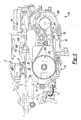
Figures 2 and3 are left and right side elevation views, respectively, of a portion of the driving tool ofFigure 1 , illustrating the frame, the motor assembly and the support in more detail; -
Figure 4 is a top plan view of a portion of the motor assembly illustrating the driver in more detail; -
Figure 5 is a perspective view of the frame, the motor assembly and the support; -
Figure 6 is a perspective view of the support; -
Figure 7 is a lateral section view of a portion of the driving tool ofFigure 1 taken through the rotational axis of the flywheel; and -
Figure 8 is an enlarged portion ofFigure 5 . - With reference to
Figure 1 of the drawings, a driving tool constructed in accordance with the teachings of the present invention is generally indicated byreference numeral 10. Thefastening tool 10 can include ahousing assembly 12, a backbone orframe 14, abackbone cover 16, adrive motor assembly 18, acontrol unit 20, anosepiece assembly 22, amagazine assembly 24, abattery pack 26 and a support 28 (Fig. 5 ). While thefastening tool 10 is illustrated as being electrically powered by a suitable power source, such as thebattery pack 26, those skilled in the art will appreciate that the invention, in its broader aspects, may be constructed somewhat differently and that aspects of the present invention may have applicability to pneumatically powered fastening tools. Furthermore, while aspects of the present invention are described herein and illustrated in the accompanying drawings in the context of a nailer, those of ordinary skill in the art will appreciate that the invention, in its broadest aspects, has further applicability. For example, thedrive motor assembly 18 may also be employed in various other mechanisms that utilize reciprocating motion, including rotary hammers, hole forming tools, such as punches, and riveting tools, such as those that install deformation rivets. - Except as otherwise described herein, the
housing assembly 12, theframe 14, thebackbone cover 16, thedrive motor assembly 18, thecontrol unit 20, thenosepiece assembly 22, themagazine assembly 24 and thebattery pack 26 can be constructed in a manner which is described inU.S. Patent Application No. 11/095,723 entitled "Method For Controlling A Power Driver" andU.S. Patent Application No. 11/095,696 entitled "Activation Arm Configuration For A Power Tool", the disclosures of which are hereby incorporated by reference as if fully set forth in detail herein. Briefly, thehousing 12 can shroud all or portions of theframe 14, thedrive motor assembly 18 and thecontrol unit 20. Theframe 14 can serve as a structure or foundation to which the backbone cover 16, thedrive motor assembly 18 thecontrol unit 20 and thenosepiece assembly 22 can be coupled. - With reference to
Figures 2 and3 , thedrive motor assembly 18 can include apower source 30, adriver 32, afollower assembly 34, which can include afollower 50, such as a roller, and areturn mechanism 36. Thepower source 30 can include amotor 40, aflywheel 42 and anactuator 44. Theflywheel 42 can be driven by themotor 40 for example via amotor pulley 254, which can be coupled for rotation with an output member of themotor 40, aflywheel pulley 300, which can be rotatably coupled to theflywheel 42, and abelt 280 that can transmit rotary power from themotor pulley 254 to theflywheel pulley 300. Theactuator 44 can be employed to move thefollower assembly 34 to drive theroller 50 toward theflywheel 42. - With additional reference to
Figure 4 , thedriver 32 can be disposed between theflywheel 42 and theroller 50 and can include an upper driver member 500 and adriver blade 502. The upper driver member 500 can include abody 510 and a pair ofprojections 512 that extend from the opposite lateral sides of thebody 510. Thebody 510 may include a driver profile 520 (Fig. 7 ), which is configured to engage theexterior surface 350 of theflywheel 42, and acam profile 522 that is disposed on a side of thebody 510 opposite the driver profile 520 (Fig. 7 ). Theprojections 512 can be employed both asreturn anchors 630, i.e., points at which thedriver 32 is coupled to the return mechanism 36 (Fig. 2 ), and asbumper tabs 632 that are used to stop downward movement of thedriver 32 after a fastener has been installed to a workpiece. - Returning to
Figures 2 and3 , thereturn mechanism 36 can include ahousing 1050, which can be coupled to theframe 14, and a pair ofreturn cords 1052 that can be engaged to thehousing 1050 and theprojections 512. Thereturn cords 1052 can be resilient to permit thedriver 32 to translate between a returned position and an extended position along atranslation axis 118; thereturn cords 1052 can bias thedriver 32 toward the returned position. - With reference to
Figures 5 and6 , thesupport 28 can include abody portion 1000 and asupport portion 1002. In the particular embodiment provided, thebody portion 1000 and thesupport portion 1002 are unitarily formed of spring steel. The body portion can be coupled or secured to theframe 14 in any desired manner, such as threaded fasteners (not shown). Thebody portion 1000 can include a span member 1008 that can span the width of theframe 14 at a location forwardly of theflywheel 42 as well as first andsecond clip structures frame 14. Thefirst clip structure 1010 can be coupled to a first side of the span member 1008 and can be a generally C-shaped bracket configured to engage a rail 1014 (Fig. 7 ) formed on a first lateral side of theframe 14. Thesecond clip structure 1012 can include atab 1016 that can be resiliently coupled to a second, opposite side of the span member 1008. Thetab 1016 can include an opening 1018 that can receive aprojection 1020 formed on theframe 14 when thebody portion 1000 is engaged to theframe 14. In this regard, thefirst clip structure 1010 can be aligned to the rail 1014 (Fig. 7 ) and thebody portion 1000 can be rotated about the rail 1014 (Fig. 7 ) to cause thetab 1016 to slip over theprojection 1020 to align the opening 1018 to theprojection 1020. The resilient configuration of thetab 1016 secures thebody portion 1000 to theframe 14, while the opening 1018 and thefirst clip structure 1010 cooperate with theprojection 1020 and the rail 1014 (Fig. 7 ), respectively, to prevent thebody portion 1000 from slipping off theframe 14. - The
support portion 1002 can be coupled to thebody portion 1000 and can be configured in any desired manner to support thebody 510 of thedriver 32 in an area proximate a location at which thedriver 32 and theflywheel 42 contact one another when energy is transmitted from theflywheel 42 to thedriver 32 to propel thedriver 32 along the translation axis 118 (Fig. 3 ). For example, thesupport portion 1002 can comprise first andsecond arms flywheel 42. - The first and
second arms first arm 1024 will suffice for both. It will be appreciated that elements of thesecond arm 1026 will be designated by the reference numerals used in the discussion of corresponding elements of thefirst arm 1024. - The
first arm 1024 can include aproximal end 1030, which can be coupled to thebody portion 1000, and asupport member 1032 that can be configured to engage a lower surface of thedriver 32, such as a lower surface of theprojections 512. In the particular example provided, thesupport member 1032 is formed on a distal, unsupportedcantilevered end 1034 of thefirst arm 1024 and anintermediate portion 1036 of thefirst arm 1024, which extends upwardly and away from thebody portion 1000 with increasing distance away from thebody portion 1000, couples the proximal anddistal ends distal end 1034 can have an arcuateupper surface 1038 that can curve downwardly. It will be appreciated that thesupport member 1032 could be configured otherwise, however, e.g., supported on two sides, and that thesupport member 1032 need only be movable away from thedriver 32 and toward theframe 14 when thetool 10 is to be actuated. The first andsecond arms U-shaped aperture 1040 that permits thesupport 28 to fit about theflywheel 42 on a side of theflywheel 42 opposite themotor 40. - With reference to
Figures 7 and8 , thebody portion 1000 can cover aspace 1044 between theflywheel 42 and theframe 14. Thesupport portion 1002 can contact anunderside 1050 of the driver (e.g., at the projections 512) and can urge thedriver 32 away from theexterior surface 350 of theflywheel 42 when theflywheel 42 is at rest, thedriver 32 is in the returned position and thefollower 50 is in the first position (shown inFig. 7 ). In the particular example illustrated, thesupport portion 1002 maintains thedriver profile 520 in a condition spaced apart from theexterior surface 350 of theflywheel 42 when theflywheel 42 is at rest, thedriver 32 is in the returned position and thefollower 50 is in the first position. - The
support 28 can reduce or eliminate contact between thedriver 32 and theflywheel 42 when thetool 10 is in a de-actuated condition. When thetool 10 is to be activated, the motor 40 (Fig. 2 ) can drive theflywheel 42 and the actuator 44 (Fig. 2 ) can move thefollower assembly 34 to cause thefollower 50 to urge thedriver 32 downwardly into engagement with therotating flywheel 42 to transfer energy from theflywheel 42 to thedriver 32. As the first andsecond arms frame 14 with thedriver 32 as thefollower 50 pushes thedriver 32 downwardly. - After actuation of the
tool 10, thereturn cords 1052 will bias thedriver 32 toward the returned position. The angled configuration of theintermediate portion 1036 of the first andsecond arms driver 32 travels to the returned position so as to reduce or eliminate contact between theflywheel 42 and thedriver 32. - While specific examples have been described in the specification and illustrated in the drawings, it will be understood by those of ordinary skill in the art that various changes may be made and equivalents may be substituted for elements thereof without departing from the scope of the present disclosure as defined in the claims. Furthermore, the mixing and matching of features, elements and/or functions between various examples is expressly contemplated herein so that one of ordinary skill in the art would appreciate from this disclosure that features, elements and/or functions of one example may be incorporated into another example as appropriate, unless described otherwise, above. Moreover, many modifications may be made to adapt a particular situation or material to the teachings of the present disclosure without departing from the essential scope thereof. Therefore, it is intended that the present disclosure not be limited to the particular examples illustrated by the drawings and described in the specification as the best mode presently contemplated for carrying out the teachings of the present disclosure, but that the scope of the present disclosure will include any embodiments falling within the foregoing description and the appended claims.
Claims (13)
- A driving tool comprising:a frame;a motor assembly coupled to the frame, the motor assembly including an electric motor, a flywheel driven by the electric motor, a pinch roller and a driver disposed between the flywheel and the pinch roller, the pinch roller being selectively movable from a first position to a second position to drive the driver into engagement with the flywheel, the driver being movable between a returned position and an extended position; anda resilient member coupled to the frame, the resilient member biasing the driver away from the flywheel to reduce or eliminate contact between the flywheel and the driver when the flywheel is at rest, the driver is in the returned position and the pinch roller is in the first position.
- The driving tool of Claim 1, wherein the resilient member includes a body and at least one arm member, the at least one arm member being coupled to the body at a first end and extending from the body toward the driver.
- The driving tool of Claim 2, wherein the at least one arm member comprises first and second arms that are disposed on opposite lateral sides of the flywheel.
- The driving tool of Claim 2, wherein the driver includes at least one projection and wherein the at least one arm member engages the at least one projection when the driver is in the returned position.
- The driving tool of Claim 1, wherein the driver has a driver body that is configured to engage the flywheel and wherein the resilient member is coupled to the frame forwardly of the flywheel such that at least a portion of the body of the driver passes over a portion of the resilient member when the driver is moved from the returned position to the extended position.
- The driving tool of Claim 5, wherein the portion of the resilient member substantially covers a space between the flywheel and the frame.
- The driving tool of Claim 1, wherein the resilient member includes at least one clip that is removably coupled to the frame.
- The driving tool of Claim 7, wherein the at least one clip includes a C-shaped bracket that engages a rail that is formed on the frame.
- The driving tool of Claim 7, wherein the at least one clip includes a tab having one of a projection and an opening, wherein the frame includes the other one of the projection and the opening and wherein the projection is received into the opening to at least partially secure the resilient member to the frame.
- The driving tool of Claim 1, wherein the driver is spaced apart from the flywheel when the driver is in the returned position.
- A method of operating a driver comprising:providing a driver that includes a frame and a motor assembly, the motor assembly being coupled to the frame and including an electric motor, a flywheel driven by the electric motor, a pinch roller and a driver disposed between the flywheel and the pinch roller, the pinch roller being selectively movable from a first position to a second position to drive the driver into engagement with the flywheel, the driver being movable between a returned position and an extended position; andsupporting the driver on opposite lateral side of the flywheel when the flywheel is at rest, the driver is in the returned position and the pinch roller is in the first position.
- The method of Claim 11, wherein supporting the driver includes resiliently biasing the driver in a direction away from the flywheel.
- The method of Claim 12, wherein supporting the driver includes coupling a pair of cantilevered arm members to the frame.
Applications Claiming Priority (1)
| Application Number | Priority Date | Filing Date | Title |
|---|---|---|---|
| US11/760,982 US7556184B2 (en) | 2007-06-11 | 2007-06-11 | Profile lifter for a nailer |
Publications (2)
| Publication Number | Publication Date |
|---|---|
| EP2002937A1 true EP2002937A1 (en) | 2008-12-17 |
| EP2002937B1 EP2002937B1 (en) | 2010-09-22 |
Family
ID=39564788
Family Applications (1)
| Application Number | Title | Priority Date | Filing Date |
|---|---|---|---|
| EP08158067A Not-in-force EP2002937B1 (en) | 2007-06-11 | 2008-06-11 | Profile lifter for a nailer |
Country Status (5)
| Country | Link |
|---|---|
| US (2) | US7556184B2 (en) |
| EP (1) | EP2002937B1 (en) |
| CN (1) | CN201325040Y (en) |
| AT (1) | ATE482057T1 (en) |
| DE (1) | DE602008002642D1 (en) |
Cited By (1)
| Publication number | Priority date | Publication date | Assignee | Title |
|---|---|---|---|---|
| EP2845689A3 (en) * | 2013-08-01 | 2016-04-13 | Basso Industry Corp. | Electric power tool |
Families Citing this family (18)
| Publication number | Priority date | Publication date | Assignee | Title |
|---|---|---|---|---|
| US9216502B2 (en) | 2008-04-03 | 2015-12-22 | Black & Decker Inc. | Multi-stranded return spring for fastening tool |
| US8534527B2 (en) * | 2008-04-03 | 2013-09-17 | Black & Decker Inc. | Cordless framing nailer |
| TWI385058B (en) * | 2010-04-26 | 2013-02-11 | Basso Ind Corp | Electric nail gun drive device |
| TWI385059B (en) * | 2010-04-27 | 2013-02-11 | Basso Ind Corp | Floating impulse unit of electric nail gun |
| DE102010030098A1 (en) * | 2010-06-15 | 2011-12-15 | Hilti Aktiengesellschaft | driving- |
| US9346158B2 (en) * | 2012-09-20 | 2016-05-24 | Black & Decker Inc. | Magnetic profile lifter |
| US9399281B2 (en) | 2012-09-20 | 2016-07-26 | Black & Decker Inc. | Stall release lever for fastening tool |
| TWI607839B (en) * | 2014-06-05 | 2017-12-11 | Basso Ind Corp | Portable power tool and impact block resetting device |
| US11325235B2 (en) | 2016-06-28 | 2022-05-10 | Black & Decker, Inc. | Push-on support member for fastening tools |
| US11267114B2 (en) | 2016-06-29 | 2022-03-08 | Black & Decker, Inc. | Single-motion magazine retention for fastening tools |
| US11400572B2 (en) | 2016-06-30 | 2022-08-02 | Black & Decker, Inc. | Dry-fire bypass for a fastening tool |
| US11279013B2 (en) * | 2016-06-30 | 2022-03-22 | Black & Decker, Inc. | Driver rebound plate for a fastening tool |
| US10987790B2 (en) | 2016-06-30 | 2021-04-27 | Black & Decker Inc. | Cordless concrete nailer with improved power take-off mechanism |
| US10926385B2 (en) | 2017-02-24 | 2021-02-23 | Black & Decker, Inc. | Contact trip having magnetic filter |
| US10933521B2 (en) | 2018-11-19 | 2021-03-02 | Brahma Industries LLC | Staple gun with self-centering mechanism |
| US11141849B2 (en) | 2018-11-19 | 2021-10-12 | Brahma Industries LLC | Protective shield for use with a staple gun |
| US10967492B2 (en) | 2018-11-19 | 2021-04-06 | Brahma Industries LLC | Staple gun with automatic depth adjustment |
| US11806854B2 (en) | 2019-02-19 | 2023-11-07 | Brahma Industries LLC | Insert for palm stapler, a palm stapler and a method of use thereof |
Citations (5)
| Publication number | Priority date | Publication date | Assignee | Title |
|---|---|---|---|---|
| US4121745A (en) | 1977-06-28 | 1978-10-24 | Senco Products, Inc. | Electro-mechanical impact device |
| EP0209916A2 (en) | 1983-03-17 | 1987-01-28 | Duo-Fast Corporation | Fastener driving tool |
| US20050218178A1 (en) * | 2004-04-02 | 2005-10-06 | Alan Berry | Lock-out for activation arm mechanism in a power tool |
| US7204403B2 (en) | 2004-04-02 | 2007-04-17 | Black & Decker Inc. | Activation arm configuration for a power tool |
| US9572305B2 (en) | 2014-06-10 | 2017-02-21 | National Central University | Phosphor diffusion sheet luminaire for agricultural lighting |
Family Cites Families (189)
| Publication number | Priority date | Publication date | Assignee | Title |
|---|---|---|---|---|
| US997638A (en) * | 1910-08-13 | 1911-07-11 | Eugene Rynearson | Pavement-breaking machine. |
| US1517101A (en) | 1920-08-30 | 1924-11-25 | Splitdorf Electrical Co | Support for electric machines |
| US1715866A (en) * | 1923-08-17 | 1929-06-04 | Firm Neufeldt & Kuhnke Betr Sg | Asynchronous machine with condensers |
| US1482464A (en) * | 1923-10-09 | 1924-02-05 | Harrison D Flegel | Sewing-machine-motor bracket |
| US1611814A (en) | 1924-05-29 | 1926-12-21 | Thomas J Butler | Gun |
| US1647493A (en) | 1924-10-10 | 1927-11-01 | Kenneth S Startup | Power hammer |
| US1600266A (en) | 1925-04-01 | 1926-09-21 | Armstrong Frederick | Clamp for holding knives |
| US1629189A (en) * | 1925-05-04 | 1927-05-17 | Frank L Weaver | Electrical connecter |
| US2320450A (en) * | 1942-07-16 | 1943-06-01 | Ismael Spencer | Belt clip for pistols |
| US2379784A (en) * | 1943-02-06 | 1945-07-03 | Ibm | Gun |
| US2697179A (en) | 1952-03-11 | 1954-12-14 | Singer Mfg Co | Ventilation of dynamoelectric machines |
| US2714209A (en) * | 1952-07-10 | 1955-08-02 | Bostitch Inc | Closure means for staple driveway |
| US2737941A (en) * | 1952-12-13 | 1956-03-13 | Marlo J Carrau | Mechanical gun |
| US2786672A (en) * | 1954-07-15 | 1957-03-26 | Mid States Gummed Paper Co | Tape-feeding mechanism |
| US2869824A (en) * | 1957-03-26 | 1959-01-20 | Raymond Int Inc | Automatic drop weight for boring |
| US3074347A (en) * | 1958-11-21 | 1963-01-22 | Tokheim Corp | Electric drive unit and mounting |
| US3018584A (en) * | 1959-06-05 | 1962-01-30 | Angelo G Passariello | Pinch-spin tops |
| US3194324A (en) * | 1963-03-13 | 1965-07-13 | Signode Corp | Fastener driving tool |
| US3172124A (en) * | 1963-04-01 | 1965-03-09 | Spotnails | Pneumatically operated fastener driving machines |
| US3215324A (en) | 1963-11-29 | 1965-11-02 | Fastener Corp | Fastener driving apparatus |
| DE1302136B (en) | 1964-03-11 | 1970-01-22 | ||
| US3293462A (en) | 1964-07-31 | 1966-12-20 | Spalding A G & Bros Inc | Power unit for toys or the like |
| US3408887A (en) | 1966-11-18 | 1968-11-05 | Standard Pressed Steel Co | Adjustable shoulder bolt for use in a stripper means |
| CH466413A (en) * | 1967-11-28 | 1968-12-15 | Mefina Sa | Device for supporting an electric motor |
| US3500940A (en) * | 1968-08-15 | 1970-03-17 | Sprague & Henwood Inc | Free fall hammer apparatus |
| US3535906A (en) | 1968-09-03 | 1970-10-27 | Dwain K Swick | Cylinder head straightening method |
| DE1943000C3 (en) * | 1969-08-23 | 1973-11-08 | Bukama Gmbh Hannover, 3005 Hemmingenwesterfeld | Feed device for fasteners that are driven in with a hand rodent, especially for nails |
| US3688138A (en) * | 1970-10-06 | 1972-08-29 | Murphy Ind Inc G W | Subframe for a power tool employing two plate-like elements with cut out portions for motor and transmission |
| US3694680A (en) | 1970-10-06 | 1972-09-26 | Murphy Ind Inc G W | Stamped shell sheet metal frame module for a power tool |
| US3700987A (en) | 1971-03-29 | 1972-10-24 | E Systems Inc | Pulse modulation motor control |
| US3817091A (en) * | 1971-05-11 | 1974-06-18 | L Frederick | Pile driver drive cap |
| US3774293A (en) | 1971-09-13 | 1973-11-27 | Signode Corp | Fastener driving tool |
| US3858780A (en) * | 1973-01-08 | 1975-01-07 | Spotnails | Fastener-driving tool |
| US3853257A (en) | 1973-06-18 | 1974-12-10 | Spotnails | Self-clearing nose section for a powered fastener-driving tool |
| US4042036A (en) | 1973-10-04 | 1977-08-16 | Smith James E | Electric impact tool |
| US3957192A (en) * | 1973-11-02 | 1976-05-18 | Joh. Friedrich Behrens Metallwaren-Fabrik | Fastener-driving tool |
| US3848309A (en) | 1973-11-12 | 1974-11-19 | Chrysler Corp | Pulley method of manufacture |
| JPS5077969U (en) | 1973-11-19 | 1975-07-07 | ||
| US3937286A (en) * | 1974-05-13 | 1976-02-10 | Wagner Carl F | Fence post driver |
| US3946486A (en) * | 1974-06-12 | 1976-03-30 | Sperry Rand Corporation | Portable electrical shaver with pivotally mounted motor |
| US4763347A (en) * | 1983-02-02 | 1988-08-09 | General Electric Company | Control system, electronically commutated motor system, blower apparatus and methods |
| NL178473B (en) * | 1974-09-03 | 1985-11-01 | Lely Nv C Van Der | SOIL TILLER. |
| JPS5411577Y2 (en) | 1974-10-25 | 1979-05-24 | ||
| DE2504094C2 (en) | 1975-01-31 | 1985-03-21 | Signode Corp., Glenview, Ill. | Catching device for the percussion piston of a pneumatically operated driving tool |
| US3934778A (en) * | 1975-02-13 | 1976-01-27 | Textron, Inc. | Staple driving device with improved staple jam clearing mechanism |
| DE2510858C2 (en) | 1975-03-12 | 1987-01-08 | Signode Corp., Glenview, Ill. | Device for intercepting the impact piston of a pneumatically operated driving tool |
| US3983429A (en) | 1975-05-08 | 1976-09-28 | Westinghouse Electric Corporation | Adjustable motor base |
| US4204622A (en) * | 1975-05-23 | 1980-05-27 | Cunningham James D | Electric impact tool |
| JPS5639881Y2 (en) | 1976-06-09 | 1981-09-17 | ||
| US4083481A (en) * | 1977-03-10 | 1978-04-11 | Motorola, Inc. | Detachable mounting clip arrangement for miniature portable apparatus or the like |
| JPS5741399Y2 (en) | 1977-03-17 | 1982-09-10 | ||
| US4323127A (en) * | 1977-05-20 | 1982-04-06 | Cunningham James D | Electrically operated impact tool |
| US4129240A (en) | 1977-07-05 | 1978-12-12 | Duo-Fast Corporation | Electric nailer |
| CH626434A5 (en) | 1977-08-02 | 1981-11-13 | Haas Eduard Volkmann | Method and device for storing kinetic energy in a centrifugal mass |
| US4179791A (en) | 1977-12-02 | 1979-12-25 | Ncr Corporation | Variable fit fastener |
| JPS54115485U (en) | 1978-02-01 | 1979-08-13 | ||
| US4206697A (en) * | 1978-02-22 | 1980-06-10 | California Processing Machinery | Method and apparatus for selective pitting of fruits of the drupe type |
| US4189080A (en) * | 1978-02-23 | 1980-02-19 | Senco Products, Inc. | Impact device |
| US4197974A (en) * | 1978-06-12 | 1980-04-15 | Speedfast Corporation | Nailer |
| US4215808A (en) * | 1978-12-22 | 1980-08-05 | Sollberger Roger W | Portable electric fastener driving apparatus |
| US4449681A (en) * | 1979-01-03 | 1984-05-22 | The Boeing Company | Aerodynamically contoured, low drag wing, engine and engine nacelle combination |
| US4298072A (en) | 1979-08-31 | 1981-11-03 | Senco Products, Inc. | Control arrangement for electro-mechanical tool |
| US4290493A (en) | 1979-09-06 | 1981-09-22 | Senco Products, Inc. | Configured impact member for driven flywheel impact device |
| US4292574A (en) | 1980-04-18 | 1981-09-29 | Anatole J. Sipin Company | Personal air sampler with electric motor driven by intermittent full-power pulses under control, between pulses, of motor's back electromotive force |
| US4566619A (en) * | 1980-07-24 | 1986-01-28 | The Kiesel Co. | Pneumatic fastener-driving tool and method |
| DE3047662C2 (en) * | 1980-12-18 | 1985-02-21 | Karl M. Reich Maschinenfabrik GmbH, 7440 Nürtingen | Buffer system for impact devices |
| US4483474A (en) | 1981-01-22 | 1984-11-20 | Signode Corporation | Combustion gas-powered fastener driving tool |
| US4403722A (en) | 1981-01-22 | 1983-09-13 | Signode Corporation | Combustion gas powered fastener driving tool |
| US4389012A (en) * | 1981-04-22 | 1983-06-21 | Duo-Fast Corporation | Fastener tool loading assembly |
| DE3119956C2 (en) * | 1981-05-20 | 1984-11-22 | Joh. Friedrich Behrens AG, 2070 Ahrensburg | Sound-damped driving tool for fasteners |
| DE3125860C2 (en) * | 1981-07-01 | 1983-12-15 | J. Wagner Gmbh, 7990 Friedrichshafen | Electrically operated hand tool |
| US4457462A (en) * | 1981-08-26 | 1984-07-03 | Taormina Umberto C | Tool holder |
| US4480513A (en) | 1981-11-16 | 1984-11-06 | Mcgard, Inc. | Bolt-lock structure |
| JPS58502044A (en) | 1981-12-10 | 1983-12-01 | カニンガム,ジエ−ムス デイ− | Electrically driven impact tools and how to operate them |
| US4436236A (en) * | 1982-03-22 | 1984-03-13 | Senco Products, Inc. | Front gate and latch assembly for the guide body of an industrial fastener driving tool |
| WO1987002611A1 (en) | 1985-10-29 | 1987-05-07 | Cunningham James D | An impact tool |
| US4558747A (en) | 1982-08-11 | 1985-12-17 | Cunningham James D | Impact devices |
| US4467952A (en) * | 1983-01-03 | 1984-08-28 | Senco Products, Inc. | Latch assembly for the front gate of the guide body of an industrial fastener driving tool |
| US5069379A (en) | 1983-03-17 | 1991-12-03 | Duo-Fast Corporation | Fastener driving tool |
| US4519535A (en) * | 1983-03-29 | 1985-05-28 | Sencorp | Flywheel for an electro-mechanical fastener driving tool |
| US4544090A (en) | 1983-03-29 | 1985-10-01 | Sencorp | Elastomeric driver return assembly for an electro-mechanical fastener driving tool |
| US4747455A (en) * | 1983-05-02 | 1988-05-31 | Jbd Corporation | High impact device and method |
| JPS59182747U (en) | 1983-05-19 | 1984-12-05 | アルプス電気株式会社 | interface circuit |
| US4635836A (en) * | 1983-12-07 | 1987-01-13 | Motorola, Inc. | Twist-off detachable belt clip assembly |
| US4828153A (en) * | 1983-12-07 | 1989-05-09 | Motorola, Inc. | Detachable belt clip assembly |
| US4572053A (en) * | 1984-02-27 | 1986-02-25 | Teleflex Incorporated | Ordnance ejector system |
| US4585747A (en) * | 1984-06-27 | 1986-04-29 | Mobil Oil Corporation | Synthesis of crystalline silicate ZSM-48 |
| US4625903A (en) | 1984-07-03 | 1986-12-02 | Sencorp | Multiple impact fastener driving tool |
| DE3506421A1 (en) | 1985-02-23 | 1986-09-04 | Heinrich Bühnen KG, 2800 Bremen | Nail-driving tool with a driver centrally symmetric in cross-section |
| US4622500A (en) | 1985-07-11 | 1986-11-11 | The Machlett Laboratories, Inc. | Electric motor controller |
| US4721170A (en) * | 1985-09-10 | 1988-01-26 | Duo-Fast Corporation | Fastener driving tool |
| US4700876A (en) | 1985-11-01 | 1987-10-20 | Arrow Fastener Company, Inc. | Staple driving tool |
| US4858813A (en) * | 1985-11-01 | 1989-08-22 | Arrow Fastener Company, Inc. | Staple driving tool |
| US4946087A (en) * | 1985-11-01 | 1990-08-07 | Arrow Fastener Company, Inc. | Staple driving tool |
| EP0306793B1 (en) | 1987-09-10 | 1992-11-11 | Siemens Aktiengesellschaft | Motor suspension using a strap encircling the motor housing |
| US4836755A (en) * | 1988-03-22 | 1989-06-06 | Durr Dental Gmbh & Co Kg | Compressor with balanced flywheel |
| US4991763A (en) * | 1988-05-23 | 1991-02-12 | Technalytics Inc. | Surgical stapler |
| US5114065A (en) * | 1988-05-23 | 1992-05-19 | Technalytics, Inc. | Surgical stapler |
| DE3831864C2 (en) * | 1988-09-20 | 1994-01-27 | Paslode Gmbh | Annular bump buffer for fastener driving tools |
| US4854492A (en) * | 1988-10-14 | 1989-08-08 | Sencorp | Flywheel for an electromechanical fastener driving tool |
| US4932480A (en) * | 1988-12-16 | 1990-06-12 | Illinois Tool Works Inc. | Driving tool with air-cooled bumper |
| US4964558A (en) | 1989-05-26 | 1990-10-23 | Sencorp | Electro-mechanical fastener driving tool |
| DE4019894A1 (en) | 1989-07-15 | 1991-04-11 | Ceka Elektrowerkzeuge Ag & Co | Hand held electric power tool with pistol grip handle - has motor and main weight concentrated in handle with short tool spindle for improved location and drive control via geared transmission |
| DE3924621A1 (en) | 1989-07-26 | 1991-01-31 | Hilti Ag | Setting tool with piston incorporated in nail gun - has radially expandable segmental brake |
| US4988069A (en) * | 1989-11-27 | 1991-01-29 | Baxter International Inc. | Stepping motor mounting |
| US5098004A (en) * | 1989-12-19 | 1992-03-24 | Duo-Fast Corporation | Fastener driving tool |
| DE3942083A1 (en) | 1989-12-20 | 1991-06-27 | Licentia Gmbh | Hand-held power tool with enhanced motor cooling - has radial and axial fans juxtaposed and keyed to motor armature shaft in space immediately ahead of downstream stator winding heads |
| US4982705A (en) * | 1990-02-21 | 1991-01-08 | Tecumseh Products Company | Cam pulley and cylinder head arrangement for an overhead cam engine |
| US5184941A (en) * | 1991-04-10 | 1993-02-09 | A. O. Smith Corporation | Mounting support for motor-pump unit |
| US5201445A (en) * | 1991-05-20 | 1993-04-13 | Axelman Bart I | Tool holder with self-stabilizing swivel mount |
| JP2541323Y2 (en) | 1991-06-21 | 1997-07-16 | 株式会社マキタ | Nail jam removal device for nailing machine |
| JP2553492Y2 (en) | 1991-10-07 | 1997-11-05 | 株式会社マキタ | Hook device in power tool |
| US5197647A (en) * | 1991-10-21 | 1993-03-30 | Illinois Tool Works Inc. | Fastener-driving tool with improved feeding mechanism |
| US5133329A (en) * | 1991-11-25 | 1992-07-28 | Illinois Tool Works Inc. | Ignition system for combustion-powered tool |
| GB9126338D0 (en) | 1991-12-11 | 1992-02-12 | Glynwed Eng | Fastener applicator |
| US5291578A (en) * | 1992-06-15 | 1994-03-01 | First Switch, Inc. | Apparatus for controlling a vehicle fuel pump |
| US5406441A (en) * | 1993-01-28 | 1995-04-11 | Warda; Gary G. | Circuit and method for controlling fastener application |
| US5511715A (en) * | 1993-02-03 | 1996-04-30 | Sencorp | Flywheel-driven fastener driving tool and drive unit |
| CO4130343A1 (en) * | 1993-02-03 | 1995-02-13 | Sencorp | ELECTROMECHANICAL TOOL TO GUIDE STAPLES |
| US5366132A (en) | 1993-04-14 | 1994-11-22 | Stanley-Bostitch, Inc. | Portable fastener driving device with inadvertent impact activation prevention |
| EP0916770B1 (en) | 1993-07-10 | 2007-01-17 | BACA Limited | Elastic rope |
| US5537025A (en) * | 1993-08-18 | 1996-07-16 | Generac Corporation | Battery charger/pre-exciter for engine-driven generator |
| US5415136A (en) * | 1993-08-30 | 1995-05-16 | Illinois Tool Works Inc. | Combined ignition and fuel system for combustion-powered tool |
| DE4340570C2 (en) * | 1993-11-29 | 2003-04-10 | Hilti Ag | Driving device for setting fasteners in recording materials |
| JP2568736Y2 (en) * | 1993-12-06 | 1998-04-15 | マックス株式会社 | Portable electric staple driving machine |
| US5495161A (en) * | 1994-01-05 | 1996-02-27 | Sencorp | Speed control for a universal AC/DC motor |
| US5445227A (en) | 1994-03-31 | 1995-08-29 | Heppner; Alden | Release mechanism for a hydraulic post driver |
| DE4414006C1 (en) | 1994-04-22 | 1995-07-06 | Mueller Erwin Gmbh & Co | Fastening and nailing device |
| WO1996012591A1 (en) * | 1994-10-21 | 1996-05-02 | Senco Products, Inc. | Pneumatic fastener driving tool and an electronic control system therefor |
| US5558264A (en) | 1995-02-13 | 1996-09-24 | Illinois Tool Works Inc. | Combustion-powered, fastener-driving tool with gas-actuated, fastener-feeding mechanism |
| DE69609537T2 (en) | 1995-02-15 | 2001-11-08 | Max Co. Ltd., Tokio/Tokyo | Screwing device with contact arm locking mechanism |
| JP3287172B2 (en) * | 1995-04-05 | 2002-05-27 | マックス株式会社 | Nailer trigger device |
| DE19521425B4 (en) | 1995-06-14 | 2007-03-29 | Robert Bosch Gmbh | Hand tool with electric motor, and their electric motor with centering rings on the front sides of the pole tube |
| DE19536557C2 (en) * | 1995-10-02 | 1998-11-26 | Wolf Gmbh Richard | Tool fastening device for technoscopes |
| JPH09155803A (en) * | 1995-12-08 | 1997-06-17 | Kioritz Corp | Power work machine |
| EP0808018B2 (en) | 1996-05-13 | 2011-06-08 | Black & Decker Inc. | Electrical power tool having a motor control circuit for providing improved control over the torque output of the power tool |
| US5810232A (en) | 1996-07-10 | 1998-09-22 | Meurer; John | Tool support |
| US5810225A (en) | 1996-11-26 | 1998-09-22 | Andrew; Richard J. | Tool support apparatus |
| US5865473A (en) * | 1997-01-21 | 1999-02-02 | Emhart Inc. | Isolated conduit system |
| DE19805577A1 (en) | 1997-02-27 | 1998-09-03 | Bosch Gmbh Robert | Electric hand machine tool |
| DE19721449C2 (en) | 1997-05-22 | 2002-04-25 | Zf Sachs Ag | Carrying structure for carrying an electric motor and actuator, comprising such a carrying structure |
| US5839638A (en) | 1997-06-26 | 1998-11-24 | Illinois Tool Works Inc | Pneumatic trim nailer |
| US5923145A (en) * | 1997-08-15 | 1999-07-13 | S-B Power Tool Company | Controller for variable speed motor |
| US5927585A (en) * | 1997-12-17 | 1999-07-27 | Senco Products, Inc. | Electric multiple impact fastener driving tool |
| EP0928667A3 (en) | 1997-12-31 | 2001-05-23 | Porter-Cable Corporation | Internal combustion fastener driving tool aluminium cylinder |
| US6158643A (en) | 1997-12-31 | 2000-12-12 | Porter-Cable Corporation | Internal combustion fastener driving tool piston and piston ring |
| US6012622A (en) * | 1998-04-20 | 2000-01-11 | Illinois Tool Works Inc. | Fastener driving tool for trim applications |
| DE29812622U1 (en) | 1998-07-15 | 1998-10-01 | Hong Bing Pneumatic Industry Co., Ltd., Shen Kang Hsiang, Taichung | Pneumatic tool |
| US5969508A (en) | 1998-07-27 | 1999-10-19 | Motorola, Inc. | Battery charging method using battery circuitry impedence measurement to determine optimum charging voltage |
| US6431430B1 (en) | 1998-09-18 | 2002-08-13 | Stanley Fastening Systems, L.P. | Battery operated roofing nailer and nails therefor |
| US6499643B1 (en) | 1998-09-18 | 2002-12-31 | Stanley Fastenening Systems, L.P. | Drive channel for nailer |
| US6422447B1 (en) * | 1998-09-18 | 2002-07-23 | Stanley Fastening Systems, L.P. | Feed system for nailer |
| JP3676609B2 (en) | 1998-09-29 | 2005-07-27 | 株式会社マキタ | Mounting structure of hanging tool in electric power tool |
| JP2000117659A (en) | 1998-10-16 | 2000-04-25 | Makita Corp | Piston damper structure for nail hammer |
| US6296065B1 (en) | 1998-12-30 | 2001-10-02 | Black & Decker Inc. | Dual-mode non-isolated corded system for transportable cordless power tools |
| DE19908300C1 (en) | 1999-02-26 | 2000-11-09 | Fein C & E | Strap holder for a hand tool |
| US6168287B1 (en) * | 1999-03-09 | 2001-01-02 | Kuo-Chen Liu | Combination of an electric-powered tool and an illuminating device received in the tool |
| JP2002540967A (en) * | 1999-04-05 | 2002-12-03 | スタンレー ファスニング システムズ エル.ピー. | Fastener driving tool safety trip assembly and trip locking mechanism |
| JP2001025982A (en) | 1999-07-13 | 2001-01-30 | Makita Corp | Power tool with lighting system improved in operability, and its use |
| US6206538B1 (en) * | 1999-08-30 | 2001-03-27 | David B. Lemoine | Miser light for cordless battery operated hand tools |
| US6672498B2 (en) * | 1999-09-17 | 2004-01-06 | Stanley Fastening Sytems Lp | Feed system for nailer |
| US6170729B1 (en) * | 2000-06-28 | 2001-01-09 | Basso Industry Corp. | Nailing depth adjusting device for a power nailer |
| AU2001284822A1 (en) | 2000-08-11 | 2002-02-25 | Stanley Fastening Systems, L.P. | Feed system for nailer |
| US6796478B2 (en) | 2000-10-12 | 2004-09-28 | Illinois Tool Works Inc. | Fuel cell adapter system for combustion tools |
| US6523860B1 (en) | 2000-10-12 | 2003-02-25 | Illinois Tool Works Inc. | Fuel cell adapter system for combustion tools |
| DE10055003B4 (en) | 2000-11-07 | 2004-07-15 | Novus Gmbh & Co. Kg | tacker |
| US6796475B2 (en) * | 2000-12-22 | 2004-09-28 | Senco Products, Inc. | Speed controller for flywheel operated hand tool |
| US6607111B2 (en) | 2000-12-22 | 2003-08-19 | Senco Products, Inc. | Flywheel operated tool |
| US6755336B2 (en) * | 2000-12-22 | 2004-06-29 | Kevin A. Harper | Return mechanism for a cyclic tool |
| US20020185514A1 (en) | 2000-12-22 | 2002-12-12 | Shane Adams | Control module for flywheel operated hand tool |
| US6669072B2 (en) | 2000-12-22 | 2003-12-30 | Senco Products, Inc. | Flywheel operated nailer |
| US6705501B2 (en) * | 2001-01-31 | 2004-03-16 | Black & Decker Inc. | Contact trip assembly for fastening tool |
| JP3553585B2 (en) * | 2001-03-02 | 2004-08-11 | 日立工機株式会社 | Electric tool |
| US20020179659A1 (en) | 2001-06-04 | 2002-12-05 | Shaw Stanly G. | Tool support and lock |
| US6604666B1 (en) | 2001-08-20 | 2003-08-12 | Tricord Solutions, Inc. | Portable electrical motor driven nail gun |
| WO2004052595A1 (en) | 2002-03-07 | 2004-06-24 | Tricord Solutions, Inc. | Enhanced electrical motor driven nail gun |
| US6705503B1 (en) * | 2001-08-20 | 2004-03-16 | Tricord Solutions, Inc. | Electrical motor driven nail gun |
| SE523684C2 (en) * | 2001-10-04 | 2004-05-11 | Isaberg Rapid Ab | Control device for a drive motor in a stapler |
| US7503401B2 (en) * | 2004-04-02 | 2009-03-17 | Black & Decker Inc. | Solenoid positioning methodology |
| US8231039B2 (en) | 2004-04-02 | 2012-07-31 | Black & Decker Inc. | Structural backbone/motor mount for a power tool |
| US8011549B2 (en) | 2004-04-02 | 2011-09-06 | Black & Decker Inc. | Flywheel configuration for a power tool |
| US8302833B2 (en) * | 2004-04-02 | 2012-11-06 | Black & Decker Inc. | Power take off for cordless nailer |
| ATE394200T1 (en) * | 2004-04-02 | 2008-05-15 | Black & Decker Inc | FASTENING TOOL WITH MODE SELECTION SWITCH |
| US8123099B2 (en) | 2004-04-02 | 2012-02-28 | Black & Decker Inc. | Cam and clutch configuration for a power tool |
| US7975893B2 (en) * | 2004-04-02 | 2011-07-12 | Black & Decker Inc. | Return cord assembly for a power tool |
| US7322506B2 (en) * | 2004-04-02 | 2008-01-29 | Black & Decker Inc. | Electric driving tool with driver propelled by flywheel inertia |
| US7055729B2 (en) * | 2004-09-24 | 2006-06-06 | Illinois Tool Works Inc. | Tool-free depth-of-drive adjustment for a fastener-driving tool |
| US6971567B1 (en) | 2004-10-29 | 2005-12-06 | Black & Decker Inc. | Electronic control of a cordless fastening tool |
| US7097084B2 (en) | 2004-12-07 | 2006-08-29 | Apach Industrial Co., Ltd. | Adjustable device for adjusting safety device of power nailers |
-
2007
- 2007-06-11 US US11/760,982 patent/US7556184B2/en active Active - Reinstated
-
2008
- 2008-06-11 AT AT08158067T patent/ATE482057T1/en not_active IP Right Cessation
- 2008-06-11 EP EP08158067A patent/EP2002937B1/en not_active Not-in-force
- 2008-06-11 DE DE602008002642T patent/DE602008002642D1/en active Active
- 2008-06-11 CN CNU2008201312617U patent/CN201325040Y/en not_active Expired - Fee Related
-
2009
- 2009-03-19 US US12/407,014 patent/US8025197B2/en active Active
Patent Citations (5)
| Publication number | Priority date | Publication date | Assignee | Title |
|---|---|---|---|---|
| US4121745A (en) | 1977-06-28 | 1978-10-24 | Senco Products, Inc. | Electro-mechanical impact device |
| EP0209916A2 (en) | 1983-03-17 | 1987-01-28 | Duo-Fast Corporation | Fastener driving tool |
| US20050218178A1 (en) * | 2004-04-02 | 2005-10-06 | Alan Berry | Lock-out for activation arm mechanism in a power tool |
| US7204403B2 (en) | 2004-04-02 | 2007-04-17 | Black & Decker Inc. | Activation arm configuration for a power tool |
| US9572305B2 (en) | 2014-06-10 | 2017-02-21 | National Central University | Phosphor diffusion sheet luminaire for agricultural lighting |
Cited By (1)
| Publication number | Priority date | Publication date | Assignee | Title |
|---|---|---|---|---|
| EP2845689A3 (en) * | 2013-08-01 | 2016-04-13 | Basso Industry Corp. | Electric power tool |
Also Published As
| Publication number | Publication date |
|---|---|
| US8025197B2 (en) | 2011-09-27 |
| DE602008002642D1 (en) | 2010-11-04 |
| US20080302852A1 (en) | 2008-12-11 |
| EP2002937B1 (en) | 2010-09-22 |
| ATE482057T1 (en) | 2010-10-15 |
| CN201325040Y (en) | 2009-10-14 |
| US20090173765A1 (en) | 2009-07-09 |
| US7556184B2 (en) | 2009-07-07 |
Similar Documents
| Publication | Publication Date | Title |
|---|---|---|
| US8025197B2 (en) | Profile lifter for a nailer | |
| EP2711134A2 (en) | Stall release lever for fastening tool | |
| US8511532B2 (en) | Fastener driving tool | |
| EP0245086B1 (en) | Motor-operated fastener driving machine | |
| US5098004A (en) | Fastener driving tool | |
| CN102056713B (en) | Cordless Row Nailer | |
| EP2716409B1 (en) | Activation system having multi-angled arm and stall release mechanism | |
| EP0412143B1 (en) | Guide anvil including movable clinching wings for stapler | |
| US8479966B2 (en) | Floating impact apparatus for electrical nail gun | |
| EP2226160B1 (en) | Power tool including a trigger lock | |
| EP1938928B1 (en) | Screwdrivers | |
| US5088200A (en) | Hair trimmer having a low-friction rotary drive | |
| EP1582305A3 (en) | Flywheel configuration for a power tool | |
| WO2005097419B1 (en) | Lock-out for activation arm mechanism in a power tool | |
| EP3689550B1 (en) | Powered fastener driver | |
| AU2017290144B2 (en) | Cordless concrete nailer with removable lower contact trip | |
| WO2025043130A1 (en) | Fastening tool driver assembly with internal lifting member | |
| US20030188878A1 (en) | Percussion tool | |
| US8157144B2 (en) | Stapler | |
| WO2024145686A1 (en) | Driver blade guide for a fastening tool | |
| JPH061336Y2 (en) | Buckling prevention device for stapler | |
| JPH0615979U (en) | Attachment mechanism of staple cartridge in electric stapler | |
| JP3918650B2 (en) | Electric stapler |
Legal Events
| Date | Code | Title | Description |
|---|---|---|---|
| PUAI | Public reference made under article 153(3) epc to a published international application that has entered the european phase |
Free format text: ORIGINAL CODE: 0009012 |
|
| AK | Designated contracting states |
Kind code of ref document: A1 Designated state(s): AT BE BG CH CY CZ DE DK EE ES FI FR GB GR HR HU IE IS IT LI LT LU LV MC MT NL NO PL PT RO SE SI SK TR |
|
| AX | Request for extension of the european patent |
Extension state: AL BA MK RS |
|
| 17P | Request for examination filed |
Effective date: 20090616 |
|
| 17Q | First examination report despatched |
Effective date: 20090715 |
|
| AKX | Designation fees paid |
Designated state(s): AT BE BG CH CY CZ DE DK EE ES FI FR GB GR HR HU IE IS IT LI LT LU LV MC MT NL NO PL PT RO SE SI SK TR |
|
| GRAP | Despatch of communication of intention to grant a patent |
Free format text: ORIGINAL CODE: EPIDOSNIGR1 |
|
| GRAS | Grant fee paid |
Free format text: ORIGINAL CODE: EPIDOSNIGR3 |
|
| GRAA | (expected) grant |
Free format text: ORIGINAL CODE: 0009210 |
|
| AK | Designated contracting states |
Kind code of ref document: B1 Designated state(s): AT BE BG CH CY CZ DE DK EE ES FI FR GB GR HR HU IE IS IT LI LT LU LV MC MT NL NO PL PT RO SE SI SK TR |
|
| REG | Reference to a national code |
Ref country code: GB Ref legal event code: FG4D |
|
| REG | Reference to a national code |
Ref country code: CH Ref legal event code: EP |
|
| REG | Reference to a national code |
Ref country code: IE Ref legal event code: FG4D |
|
| REF | Corresponds to: |
Ref document number: 602008002642 Country of ref document: DE Date of ref document: 20101104 Kind code of ref document: P |
|
| REG | Reference to a national code |
Ref country code: SE Ref legal event code: TRGR |
|
| PG25 | Lapsed in a contracting state [announced via postgrant information from national office to epo] |
Ref country code: FI Free format text: LAPSE BECAUSE OF FAILURE TO SUBMIT A TRANSLATION OF THE DESCRIPTION OR TO PAY THE FEE WITHIN THE PRESCRIBED TIME-LIMIT Effective date: 20100922 Ref country code: NO Free format text: LAPSE BECAUSE OF FAILURE TO SUBMIT A TRANSLATION OF THE DESCRIPTION OR TO PAY THE FEE WITHIN THE PRESCRIBED TIME-LIMIT Effective date: 20101222 Ref country code: AT Free format text: LAPSE BECAUSE OF FAILURE TO SUBMIT A TRANSLATION OF THE DESCRIPTION OR TO PAY THE FEE WITHIN THE PRESCRIBED TIME-LIMIT Effective date: 20100922 Ref country code: LT Free format text: LAPSE BECAUSE OF FAILURE TO SUBMIT A TRANSLATION OF THE DESCRIPTION OR TO PAY THE FEE WITHIN THE PRESCRIBED TIME-LIMIT Effective date: 20100922 |
|
| REG | Reference to a national code |
Ref country code: NL Ref legal event code: VDEP Effective date: 20100922 |
|
| LTIE | Lt: invalidation of european patent or patent extension |
Effective date: 20100922 |
|
| PG25 | Lapsed in a contracting state [announced via postgrant information from national office to epo] |
Ref country code: SI Free format text: LAPSE BECAUSE OF FAILURE TO SUBMIT A TRANSLATION OF THE DESCRIPTION OR TO PAY THE FEE WITHIN THE PRESCRIBED TIME-LIMIT Effective date: 20100922 Ref country code: HR Free format text: LAPSE BECAUSE OF FAILURE TO SUBMIT A TRANSLATION OF THE DESCRIPTION OR TO PAY THE FEE WITHIN THE PRESCRIBED TIME-LIMIT Effective date: 20100922 Ref country code: PL Free format text: LAPSE BECAUSE OF FAILURE TO SUBMIT A TRANSLATION OF THE DESCRIPTION OR TO PAY THE FEE WITHIN THE PRESCRIBED TIME-LIMIT Effective date: 20100922 |
|
| PG25 | Lapsed in a contracting state [announced via postgrant information from national office to epo] |
Ref country code: LV Free format text: LAPSE BECAUSE OF FAILURE TO SUBMIT A TRANSLATION OF THE DESCRIPTION OR TO PAY THE FEE WITHIN THE PRESCRIBED TIME-LIMIT Effective date: 20100922 Ref country code: GR Free format text: LAPSE BECAUSE OF FAILURE TO SUBMIT A TRANSLATION OF THE DESCRIPTION OR TO PAY THE FEE WITHIN THE PRESCRIBED TIME-LIMIT Effective date: 20101223 |
|
| PG25 | Lapsed in a contracting state [announced via postgrant information from national office to epo] |
Ref country code: IT Free format text: LAPSE BECAUSE OF FAILURE TO SUBMIT A TRANSLATION OF THE DESCRIPTION OR TO PAY THE FEE WITHIN THE PRESCRIBED TIME-LIMIT Effective date: 20100922 Ref country code: IS Free format text: LAPSE BECAUSE OF FAILURE TO SUBMIT A TRANSLATION OF THE DESCRIPTION OR TO PAY THE FEE WITHIN THE PRESCRIBED TIME-LIMIT Effective date: 20110122 Ref country code: SK Free format text: LAPSE BECAUSE OF FAILURE TO SUBMIT A TRANSLATION OF THE DESCRIPTION OR TO PAY THE FEE WITHIN THE PRESCRIBED TIME-LIMIT Effective date: 20100922 Ref country code: RO Free format text: LAPSE BECAUSE OF FAILURE TO SUBMIT A TRANSLATION OF THE DESCRIPTION OR TO PAY THE FEE WITHIN THE PRESCRIBED TIME-LIMIT Effective date: 20100922 Ref country code: EE Free format text: LAPSE BECAUSE OF FAILURE TO SUBMIT A TRANSLATION OF THE DESCRIPTION OR TO PAY THE FEE WITHIN THE PRESCRIBED TIME-LIMIT Effective date: 20100922 Ref country code: CZ Free format text: LAPSE BECAUSE OF FAILURE TO SUBMIT A TRANSLATION OF THE DESCRIPTION OR TO PAY THE FEE WITHIN THE PRESCRIBED TIME-LIMIT Effective date: 20100922 Ref country code: NL Free format text: LAPSE BECAUSE OF FAILURE TO SUBMIT A TRANSLATION OF THE DESCRIPTION OR TO PAY THE FEE WITHIN THE PRESCRIBED TIME-LIMIT Effective date: 20100922 Ref country code: PT Free format text: LAPSE BECAUSE OF FAILURE TO SUBMIT A TRANSLATION OF THE DESCRIPTION OR TO PAY THE FEE WITHIN THE PRESCRIBED TIME-LIMIT Effective date: 20110124 |
|
| PG25 | Lapsed in a contracting state [announced via postgrant information from national office to epo] |
Ref country code: BE Free format text: LAPSE BECAUSE OF FAILURE TO SUBMIT A TRANSLATION OF THE DESCRIPTION OR TO PAY THE FEE WITHIN THE PRESCRIBED TIME-LIMIT Effective date: 20100922 |
|
| PG25 | Lapsed in a contracting state [announced via postgrant information from national office to epo] |
Ref country code: ES Free format text: LAPSE BECAUSE OF FAILURE TO SUBMIT A TRANSLATION OF THE DESCRIPTION OR TO PAY THE FEE WITHIN THE PRESCRIBED TIME-LIMIT Effective date: 20110102 |
|
| PLBE | No opposition filed within time limit |
Free format text: ORIGINAL CODE: 0009261 |
|
| STAA | Information on the status of an ep patent application or granted ep patent |
Free format text: STATUS: NO OPPOSITION FILED WITHIN TIME LIMIT |
|
| 26N | No opposition filed |
Effective date: 20110623 |
|
| PG25 | Lapsed in a contracting state [announced via postgrant information from national office to epo] |
Ref country code: DK Free format text: LAPSE BECAUSE OF FAILURE TO SUBMIT A TRANSLATION OF THE DESCRIPTION OR TO PAY THE FEE WITHIN THE PRESCRIBED TIME-LIMIT Effective date: 20100922 |
|
| REG | Reference to a national code |
Ref country code: DE Ref legal event code: R097 Ref document number: 602008002642 Country of ref document: DE Effective date: 20110623 |
|
| PG25 | Lapsed in a contracting state [announced via postgrant information from national office to epo] |
Ref country code: MT Free format text: LAPSE BECAUSE OF FAILURE TO SUBMIT A TRANSLATION OF THE DESCRIPTION OR TO PAY THE FEE WITHIN THE PRESCRIBED TIME-LIMIT Effective date: 20100922 |
|
| REG | Reference to a national code |
Ref country code: FR Ref legal event code: ST Effective date: 20120229 |
|
| REG | Reference to a national code |
Ref country code: IE Ref legal event code: MM4A |
|
| PG25 | Lapsed in a contracting state [announced via postgrant information from national office to epo] |
Ref country code: IE Free format text: LAPSE BECAUSE OF NON-PAYMENT OF DUE FEES Effective date: 20110611 Ref country code: FR Free format text: LAPSE BECAUSE OF NON-PAYMENT OF DUE FEES Effective date: 20110630 |
|
| REG | Reference to a national code |
Ref country code: CH Ref legal event code: PL |
|
| REG | Reference to a national code |
Ref country code: CH Ref legal event code: PL |
|
| PG25 | Lapsed in a contracting state [announced via postgrant information from national office to epo] |
Ref country code: CH Free format text: LAPSE BECAUSE OF NON-PAYMENT OF DUE FEES Effective date: 20120630 Ref country code: MC Free format text: LAPSE BECAUSE OF NON-PAYMENT OF DUE FEES Effective date: 20110630 Ref country code: LI Free format text: LAPSE BECAUSE OF NON-PAYMENT OF DUE FEES Effective date: 20120630 |
|
| PG25 | Lapsed in a contracting state [announced via postgrant information from national office to epo] |
Ref country code: LU Free format text: LAPSE BECAUSE OF NON-PAYMENT OF DUE FEES Effective date: 20110611 Ref country code: CY Free format text: LAPSE BECAUSE OF FAILURE TO SUBMIT A TRANSLATION OF THE DESCRIPTION OR TO PAY THE FEE WITHIN THE PRESCRIBED TIME-LIMIT Effective date: 20100922 |
|
| PG25 | Lapsed in a contracting state [announced via postgrant information from national office to epo] |
Ref country code: TR Free format text: LAPSE BECAUSE OF FAILURE TO SUBMIT A TRANSLATION OF THE DESCRIPTION OR TO PAY THE FEE WITHIN THE PRESCRIBED TIME-LIMIT Effective date: 20100922 Ref country code: BG Free format text: LAPSE BECAUSE OF FAILURE TO SUBMIT A TRANSLATION OF THE DESCRIPTION OR TO PAY THE FEE WITHIN THE PRESCRIBED TIME-LIMIT Effective date: 20101222 |
|
| PG25 | Lapsed in a contracting state [announced via postgrant information from national office to epo] |
Ref country code: HU Free format text: LAPSE BECAUSE OF FAILURE TO SUBMIT A TRANSLATION OF THE DESCRIPTION OR TO PAY THE FEE WITHIN THE PRESCRIBED TIME-LIMIT Effective date: 20100922 |
|
| PGFP | Annual fee paid to national office [announced via postgrant information from national office to epo] |
Ref country code: SE Payment date: 20190611 Year of fee payment: 12 |
|
| PG25 | Lapsed in a contracting state [announced via postgrant information from national office to epo] |
Ref country code: SE Free format text: LAPSE BECAUSE OF NON-PAYMENT OF DUE FEES Effective date: 20200612 |
|
| REG | Reference to a national code |
Ref country code: SE Ref legal event code: EUG |
|
| PGFP | Annual fee paid to national office [announced via postgrant information from national office to epo] |
Ref country code: GB Payment date: 20220425 Year of fee payment: 15 Ref country code: DE Payment date: 20220420 Year of fee payment: 15 |
|
| REG | Reference to a national code |
Ref country code: DE Ref legal event code: R119 Ref document number: 602008002642 Country of ref document: DE |
|
| GBPC | Gb: european patent ceased through non-payment of renewal fee |
Effective date: 20230611 |
|
| PG25 | Lapsed in a contracting state [announced via postgrant information from national office to epo] |
Ref country code: DE Free format text: LAPSE BECAUSE OF NON-PAYMENT OF DUE FEES Effective date: 20240103 Ref country code: GB Free format text: LAPSE BECAUSE OF NON-PAYMENT OF DUE FEES Effective date: 20230611 |