EP2002888A2 - Reaction apparatus, method for assembling reaction apparatus and package for storing reactor - Google Patents
Reaction apparatus, method for assembling reaction apparatus and package for storing reactor Download PDFInfo
- Publication number
- EP2002888A2 EP2002888A2 EP07715018A EP07715018A EP2002888A2 EP 2002888 A2 EP2002888 A2 EP 2002888A2 EP 07715018 A EP07715018 A EP 07715018A EP 07715018 A EP07715018 A EP 07715018A EP 2002888 A2 EP2002888 A2 EP 2002888A2
- Authority
- EP
- European Patent Office
- Prior art keywords
- reactor
- opening
- supply
- discharge
- pipe
- Prior art date
- Legal status (The legal status is an assumption and is not a legal conclusion. Google has not performed a legal analysis and makes no representation as to the accuracy of the status listed.)
- Withdrawn
Links
Images




Classifications
-
- B—PERFORMING OPERATIONS; TRANSPORTING
- B01—PHYSICAL OR CHEMICAL PROCESSES OR APPARATUS IN GENERAL
- B01J—CHEMICAL OR PHYSICAL PROCESSES, e.g. CATALYSIS OR COLLOID CHEMISTRY; THEIR RELEVANT APPARATUS
- B01J19/00—Chemical, physical or physico-chemical processes in general; Their relevant apparatus
- B01J19/24—Stationary reactors without moving elements inside
- B01J19/248—Reactors comprising multiple separated flow channels
- B01J19/249—Plate-type reactors
-
- B—PERFORMING OPERATIONS; TRANSPORTING
- B01—PHYSICAL OR CHEMICAL PROCESSES OR APPARATUS IN GENERAL
- B01L—CHEMICAL OR PHYSICAL LABORATORY APPARATUS FOR GENERAL USE
- B01L3/00—Containers or dishes for laboratory use, e.g. laboratory glassware; Droppers
- B01L3/56—Labware specially adapted for transferring fluids
- B01L3/565—Seals
-
- B—PERFORMING OPERATIONS; TRANSPORTING
- B01—PHYSICAL OR CHEMICAL PROCESSES OR APPARATUS IN GENERAL
- B01J—CHEMICAL OR PHYSICAL PROCESSES, e.g. CATALYSIS OR COLLOID CHEMISTRY; THEIR RELEVANT APPARATUS
- B01J2219/00—Chemical, physical or physico-chemical processes in general; Their relevant apparatus
- B01J2219/24—Stationary reactors without moving elements inside
- B01J2219/2401—Reactors comprising multiple separate flow channels
- B01J2219/245—Plate-type reactors
- B01J2219/2461—Heat exchange aspects
- B01J2219/2467—Additional heat exchange means, e.g. electric resistance heaters, coils
-
- B—PERFORMING OPERATIONS; TRANSPORTING
- B01—PHYSICAL OR CHEMICAL PROCESSES OR APPARATUS IN GENERAL
- B01J—CHEMICAL OR PHYSICAL PROCESSES, e.g. CATALYSIS OR COLLOID CHEMISTRY; THEIR RELEVANT APPARATUS
- B01J2219/00—Chemical, physical or physico-chemical processes in general; Their relevant apparatus
- B01J2219/24—Stationary reactors without moving elements inside
- B01J2219/2401—Reactors comprising multiple separate flow channels
- B01J2219/245—Plate-type reactors
- B01J2219/2469—Feeding means
- B01J2219/247—Feeding means for the reactants
-
- B—PERFORMING OPERATIONS; TRANSPORTING
- B01—PHYSICAL OR CHEMICAL PROCESSES OR APPARATUS IN GENERAL
- B01L—CHEMICAL OR PHYSICAL LABORATORY APPARATUS FOR GENERAL USE
- B01L3/00—Containers or dishes for laboratory use, e.g. laboratory glassware; Droppers
- B01L3/50—Containers for the purpose of retaining a material to be analysed, e.g. test tubes
- B01L3/502—Containers for the purpose of retaining a material to be analysed, e.g. test tubes with fluid transport, e.g. in multi-compartment structures
- B01L3/5027—Containers for the purpose of retaining a material to be analysed, e.g. test tubes with fluid transport, e.g. in multi-compartment structures by integrated microfluidic structures, i.e. dimensions of channels and chambers are such that surface tension forces are important, e.g. lab-on-a-chip
Definitions
- Another aspect of the reacting apparatus of the invention includes the reactor containing package mentioned above and a reactor connected with the supply pipe and the discharge pipe.
Landscapes
- Chemical & Material Sciences (AREA)
- Chemical Kinetics & Catalysis (AREA)
- Organic Chemistry (AREA)
- Health & Medical Sciences (AREA)
- Clinical Laboratory Science (AREA)
- Physical Or Chemical Processes And Apparatus (AREA)
Abstract
Description
- The present invention relates to a reacting apparatus for reacting and discharging a fluid supplied from an outside by a predetermined method and a method of assembling the reacting apparatus, as well as a reactor containing package constituting the reacting apparatus.
- In recent years, there is proposed a reacting apparatus containing a reactor made of a ceramic inside a package brought into a vacuum state. This is a small-sized apparatus for reacting and discharging a fluid supplied from an outside by a predetermined method and can also be used in, for example, a portable apparatus or the like. According to the reacting apparatus, the reactor is contained inside the package brought into the vacuum state, and therefore, heat generated in a reaction is reduced from being transferred to an outside of the package and power generation loss can be reduced. Patent citation 1: Japanese Unexamined Patent Publication
JP-A 2003-2602 - However, the reactor made of the ceramic is provided with a large shrinkage rate in sintering the ceramic, and therefore, when, for example, a plurality of openings are formed on a surface of the reactor, an accuracy of a pitch of the openings becomes low, and there is a possibility that a positional accuracy in attaching a supply pipe to supply the fluid into the reactor and a discharge pipe to discharge the fluid after the reaction from the reactor at the reactor becomes low. As a result, positions of the supply pipe and the discharge pipe provided at the package and the respective openings provided on the surface of the reactor are shifted and there is a case in which it is difficult to bond the supply pipe and the discharge pipe respectively to the corresponding openings in airtight. Thereby, an inside of the package cannot be brought into the vacuum state, and therefore, the heat generated inside the package is escaped to an outside, as a result, it is difficult to achieve a reduction in the power generation loss.
- Further, even when the reactor is formed of a material other than ceramic, there is a possibility that the positions of the openings are shifted from predetermined positions by a dispersion in fabrication and the positional accuracy in attaching the supply pipe and the discharge pipe to the reactor becomes low. Further, thereby, it is difficult to respectively bond the supply pipe and the discharge pipe to the corresponding openings in airtight, an inside of the package cannot be brought into the vacuum state, and therefore, the heat generated inside the package is escaped to the outside, as a result, there is a case in which it is difficult to achieve the reduction in the power generation loss.
- On the other hand, in a related art, there is adopted a method of mounting a plurality of parts of the supply pipe, the discharge pipe and the like successively individually to the package, according to the method, stresses in individual bonding are accumulated, a warp is liable to be brought about at a vicinity of a boding portion of the package, and when the package is constituted by bonding a plurality of parts of, for example, a base body and a lid, there is a case in which it is difficult to seal the package in airtight. Further, when the warp is brought about as described above, it is difficult to bring the package into the vacuum state, and heat generated in reacting a substance inside the package is transferred to an outside of the package. As a result, it is difficult to achieve the reduction in the power generation loss.
- Further, when a chemical reaction inside the reactor is an endothermic reaction, in order to progress the reaction in the reactor, it is necessary to maintain a reaction temperature at a constant temperature by heating the reactor by a heater or the like, a temperature of the reactor is liable to be lowered by conducting heat generated inside the reactor as described above to a reactor container.
- However, when a heat generating amount of the heater is increased for maintaining the reaction temperature, an electric capacity used for heating by the heater is increased, as a result, there poses a problem that a power generation loss of a total of a micro reactor system is increased.
- The invention has been carried out in order to resolve the problem, and it is an object thereof to provide a reacting apparatus having a small power generation loss and an assembling method thereof, as well as a reactor containing package constituting the reacting apparatus.
- One aspect of a reacting apparatus of the invention includes a reactor having a supply port to which a fluid before a reaction is introduced and a discharge port from which the fluid after the reaction is delivered on a surface thereof; a first connecting member connected to the surface of the reactor and having a through hole associated with the supply port and a second connecting member connected to the surface of the reactor and having a through hole associated with the discharge port; a supply pipe connected to the supply port by way of the through hole of the first connecting member, to supply the fluid before the reaction to the supply port; and a discharge pipe connected to the discharge port by way of the through hole of the second connecting member, to discharge the fluid after the reaction from the discharge port. The supply port comprises a portion covered by a surface of the first connecting member and a portion communicating with the through hole of the first connecting member, or comprises only a portion communicating with the through hole of the first connecting member. The discharge port comprises a portion covered by a surface of the second connecting member and a portion communicating with the through hole of the second connecting member, or comprises only a portion communicating with the through hole of the first connecting member. A first opening of the through hole of the first connecting member comprises a portion covered by the surface of the reactor and a portion communicating with the supply port. A second opening of the through hole of the second connecting member comprises a portion covered by the surface of the reactor and a portion communicating with the discharge port.
- One aspect of a method of assembling a reacting apparatus according to the invention is a method of assembling a reacting apparatus by connecting the supply pipe to supply a fluid before a reaction and the discharge pipe to discharge the fluid after the reaction from a discharge port to a supply port to introduce the fluid before the reaction and the discharge port to deliver the fluid after the reaction respectively provided to the reactor, respectively. The supply pipe includes an end portion provided with a first opening associated with the supply port, and the discharge pipe includes an end portion provided with a second opening associated with the discharge port. The assembling method includes an arranging step of respectively arranging a first connecting member having a first through hole associated with the supply port and a second connecting member having a second through hole associated with the discharge port on a surface of the reactor such that the first through hole and the second through hole are apart from each other by a predetermined distance, and a connecting step of simultaneously connecting the first opening and the second opening to the first through hole and the second through hole.
- One aspect of a reactor containing package of the invention includes a housing having a hollow portion to contain a reactor and having an opening communicated with the hollow portion on a surface thereof, and a plate-like member to cover the opening and having through holes penetrating a supply pipe and a discharge pipe connected to the reactor.
- Further, Another aspect of the reacting apparatus of the invention includes the reactor containing package mentioned above and a reactor connected with the supply pipe and the discharge pipe.
- According to one aspect of the reacting apparatus of the invention, even when a pitch accuracy of the supply port and the discharge port formed at the reactor is low, the supply port and the discharge port as well as the supply pipe and the discharge pipe corresponding thereto can be connected in airtight, and heat necessary for a reaction in the reactor can be restrained from escaping to the outside. Therefore, the reacting apparatus having a small power generation loss can be realized.
- Further, according to one aspect of the method of assembling a reacting apparatus of the invention, even when a pitch accuracy of the supply port and the discharge port formed at the reactor is low, the supply port and the discharge port as well as the supply pipe and the discharge pipe corresponding thereto can be connected in airtight, and heat necessary for a reaction in the reactor can be restrained from escaping to the outside. Therefore, the reacting apparatus having a small power generation loss can be assembled.
- According to the reactor containing package of the invention, a heat amount transferred from the reactor inside thereof to the outside of the package can efficiently be reduced and the power generation loss can be reduced.
- Further, according to the reacting apparatus using the reactor containing package, an insulating property at the inside thereof can excellently be maintained, and therefore, the power generation loss can be reduced.
-
-
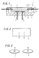
Fig. 1 is a sectional view showing a constitution example of a reacting apparatus according to a first embodiment of the invention. -
Fig. 2 is a bottom view of a reactor in the reacting apparatus shown inFig. 1 . -
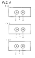
Fig. 3 is a view showing a constitution example of a plate in the reacting apparatus shown inFig. 1 . -
Fig. 4 is views showing positional relationships of a supply port and a discharge port, and through holes of the plate. -
Fig. 5 is sectional views showing a positional relationship between the supply port of the reactor and the through hole of the plate. -
Fig. 6 is a view showing an example of change of shape of the plate in the reacting apparatus. -
Fig. 7 is a bottom view of the reactor that the plate inFig. 6 is bonded to a surface thereof. -
Fig. 8 is a sectional view showing an example of change of shape of a reacting apparatus according to the first embodiment of the invention. -
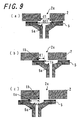
Fig. 9 is sectional views showing positional relationships between the supply port of the reactor and the through hole of the supply pipe in the reacting apparatus shown inFig. 8 . -
Fig. 10 is a sectional view showing a constitution example of a reacting apparatus according to a second embodiment of the invention. -
Fig. 11 is a bottom view of the reacting apparatus shown inFig. 10 . -
Fig. 12 is a bottom view of a reacting apparatus in the case where a plate-like member different from that of the reacting apparatus inFig. 11 is used. -
Fig. 13 is a sectional view showing another constitution example of another reacting apparatus according to the first embodiment of the invention. - Now referring to the drawings, embodiments of the invention are described in detail below.
-
Fig. 1 is a sectional view showing a constitution example of a reacting apparatus according to a first embodiment of the invention, andFig. 2 is a bottom view of a reactor in the reacting apparatus shown inFig. 1 . As shown inFig. 1 and Fig. 2 , a reactingapparatus 1 according to the embodiment includes areactor 2 having asupply port 2a and adischarge port 2b, aplate 3 having a through hole 3a, aplate 4 having a through hole 4a, asupply pipe 5 inserted to the through hole 3a, adischarge pipe 6 inserted to the through hole 4a, and apackage 7 to contain thereactor 2. Further, the reactingapparatus 1 may include anelectrode 8 on a surface of thereactor 2 and include aninsertion hole 10 to insert alead terminal 9 to thepackage 7. At this occasion, theelectrode 8 provided on the surface of thereactor 2 is electrically connected to thelead terminal 9 by way of abonding wire 11. Further, theinsertion hole 10 is arranged with aseal member 12 to seal and fix thelead terminal 9 while insulating thelead terminal 9. Further, although inFig. 1 , thepackage 7 is constituted by abase body 13 having a cavity and alid 14 to cover the cavity, a number and shapes of members constituting thepackage 7 are arbitrary. - The
reactor 2 is made of, for example, a ceramics. As shown inFig. 2 , thereactor 2 includes thesupply port 2a to which a fluid before a reaction is introduced and thedischarge port 2b from which the fluid after the reaction is delivered. Thereactor 2 generates a hydrogen gas (the fluid after the reaction) by introducing a mixture gas of an alcoholic gas fuel and oxygen (fluid before the reaction) to thesupply port 2a. A fluid after the reaction (hydrogen gas) is delivered from thedischarge port 2b of thereactor 2. - When the
reactor 2 is formed by an aluminum oxide sintered body of a dense quality having, for example, a relative density equal to or larger than 95%, for example, first, a raw material powder of the aluminum oxide sintered body is prepared by adding and mixing a sinter promoter of a rare earth oxide powder, an aluminum oxide powder or the like to an aluminum oxide powder. Successively, a green sheet of a predetermined thickness is fabricated by preparing a paste by adding and mixing an organic binder and a dispersion medium to the raw material powder, and subjecting the paste to a doctor blade method, or by preparing a product by adding the organic binder to the rawmaterial powder, and subjecting the product to pressing molding or rolling molding. Thereafter, after positioning and laminating and press-contacting a predetermined number of sheets of sheet-like compacts, the laminate is fired at a temperature of a sinter maximum temperature of 1200 through 1500°C in, for example, a nonoxidizing atmosphere to thereby provide the aimedreactor 2 made of the ceramics. Further, a molding may be carried out by a powder molding press method. - Further, a groove portion to make a reacting substance flow through can be formed inside the ceramic reactor in fabricating the green sheet by providing a penetrated portion of a predetermined shape and successively laminating and pressure-contacting another green sheet. A catalyst to react a substance may be borne on a portion constituting a side surface of the groove portion.
- When a reaction of a substance introduced into the
reactor 2 is an endothermic reaction, an inside of thereactor 2 is formed with a temperature adjusting mechanism, for example, a thin film heater (not illustrated) or a thick film heater (not illustrated) comprising a resistance layer or the like, and the surface is formed with theelectrode 8 as a terminal to supply power to the heater. A reaction of a substance can excellently be promoted by adjusting the inside of thereactor 2 by a temperature condition of, for example, about 200 to 800°C corresponding to a condition of reacting the substance by the temperature adjusting mechanism. - The heater is arranged inside a groove portion or inside an air gap at which a reaction is carried out in the
reactor 2, or in a vicinity thereof. By such a constitution, heat generated from the heater can efficiently be used for reacting a substance. -
Fig. 3 shows an example of theplates reactor 2. Theplate 3 includes the through hole 3a associated with thesupply port 2a of thereactor 2 and theplate 4 includes the through hole 4a associated with thedischarge port 2b of thereactor 2. Theplate 3 is used to connect thesupply port 2a of thereactor 2 and thesupply pipe 5, and theplate 4 is used to connect thedischarge port 2b of thereactor 2 and thedischarge pipe 6. Specifically, thesupply port 2a and thesupply pipe 5 and thedischarge port 2b and thedischarge pipe 6 are respectively connected by inserting an end portion of thesupply pipe 5 to the through hole 3a of theplate 3 and inserting an end portion of thedischarge pipe 6 to the through hole 4a of theplate 4. Further, a method of connecting thesupply pipe 5 to thesupply port 2a by way of the through hole 3a and a method of connecting thedischarge pipe 6 to thedischarge port 2b by way of the through hole 4a are not limited to insertion but, for example, thesupply pipe 5 may be connected to a surrounding of an opening of the through hole 3a of theplate 3 and thedischarge pipe 6 may be connected to a surrounding of an opening of the through hole 4a of theplate 4. Further, in the specification, there is a case in which "bonding" is referred to as "connecting". - Further, the
plates - Further, the
supply pipe 5 and thedischarge pipe 6 are respectively a supply path and a discharge path of a raw material or various fluids of a gas fluid or the like. These are formed by, for example, a ceramic material such as Al2O3 sintered body, 3Al2O3·2SiO2 sintered body, SiC sinteredbody, AlN sintered body, Si3N4 sintered body, or a glass ceramic sintered body, SUS-based metal material, Fe-Ni alloy, Fe-Ni-Co alloy, a highly heat resistant resin material such as polyimide, or glass. Thesupply pipe 5 and thedischarge pipe 6 may preferably be difficult to be embrittled by a substance included in a reacting gas. Examples of such a material include Fe alloy, ceramics and glass. - In the reacting
apparatus 1 shown inFig. 1 , thesupply pipe 5 and thedischarge pipe 6 are respectively connected to be fixed to thepackage 7, in this case, thebase body 13. A distance between the through holes 3a and 4a are set to be equal to a distance between thesupply pipe 5 and thedischarge pipe 6 such that thesupplypipe 5 and thedischarge pipe 6 are inserted. Therefore, when the through hole 3a and thesupply port 2a as well as the through hole 4a and thedischarge port 2b are respectively communicated with each other, by respectively connecting thesupply pipe 5 and thedischarge pipe 6 associated with the through holes 3a and 4a, thesupply pipe 5 and thedischarge pipe 6 can respectively be connected in association with thesupply port 2a and thedischarge port 2b. - Here, only a portion of the
supply port 2a may be communicated with the through hole 3a. That is, a portion of thesupply port 2a may be covered by theplate 3 and another portion thereof may be communicated with the through hole 3a. By closing the portion which is not communicated with the throughhole 2a by theplate 3, a fluid can be prevented from leaking from thesupply port 2a. Similarly, a portion of thedischarge port 2b may be covered by theplate 4 and other portion may be communicated with the through hole 4a. - That is, in the reacting
apparatus 1 shown inFig. 1 , even when a position of a center of thesupply port 2a and a position of a center of thedischarge port 2b are more or less shifted from positions of centers of openings of the corresponding through holes 3a and 3b, thesupply port 2a and thesupply pipe 5 as well as thesupply port 2a and thedischarge pipe 6 can respectively be connected.Fig. 4 illustrates views respectively showing positional relationships of thesupply port 2a and the through hole 3a, and thedischarge port 2a and the through hole 3b, respectively.Fig. 4 (a) shows a case in which the position of the center of thesupply port 2a and the position of the center of thedischarge port 2b coincide with the positions of the centers of the openings of the corresponding through hole 3a and 3b, andFig. 4 (b) and Fig. 4 (c) show cases in which the position of the center of thesupply port 2a and the position of the center of thedischarge port 2b are shifted from the positions of the centers of the openings of the corresponding through holes 3a and 3b. - According to the reacting
apparatus 1 according to the embodiment, even when the positions of thesupply port 2a provided on the surface of thereactor 2 and the position of the opening of thesupply pipe 5 attached to thepackage 7 are shifted, by respectively communicating the through hole 3a and thesupply pipe 3 as well as the through hole 3a and thesupply port 2a, thesupply pipe 5 and thesupply port 2a can be connected. That is, the shift of the position of thesupply port 2a and the position of the opening of thesupply pipe 5 can be adjusted by the through hole 3a of theplate 3. Similarly, even when the position of thedischarge port 2b provided on the surface of thereactor 2 and the position of the opening of thedischarge pipe 6 attached to thepackage 7 are shifted, by respectively communicating the through hole 4a and thedischarge pipe 4 as well as the through hole 4a and thedischarge port 2b, thedischarge pipe 6 and thedischarge port 2b can be connected. That is, the shift of the position of thedischarge port 2b and the position of the opening of thedischarge pipe 6 can be adjusted by the through hole 4a of theplate 4. -
Fig. 5 is sectional views showing a positional relationship between thesupply port 2a of thereactor 2 and the through hole 3a of theplate 3.Fig. 5(a) shows a case in which thesupply port 2a is communicated with the through hole 3a,Fig. 5 (b) and Fig. 5(c) show a case in which a portion of thesupply port 2a is covered by theplate 3 and the other portion thereof is communicated with the through hole 3a, andFig. 5 (d) and Fig. 5 (f) show a case in which all of thesupply port 2a is covered by theplate 3. In the case in which thesupply port 2a and the through hole 3a are communicated with each other, when one edge Ta of the opening of the through hole 3a is shifted from one edge Tb of thesupply port 2a associated with the one edge Ta to a side of thesupply port 2a by a distance L1, 0≤L1<d1 and 0≤L1<S1 are established, and when shifted to a side opposed to thesupply port 2a by a distance L2, 0≤L2<D1 is established, wherein d1 denotes an opening diameter of thesupply port 2a, D1 denotes an opening diameter of the through hole 3a, and S1 denotes a distance between one edge of the opening of the through hole 3a and an outer peripheral edge of theplate 3. Further, the same goes with a case in which thesupply port 2a and the through hole 3a of theplate 3 are respectively regarded as thedischarge port 2b and the through hole 4a of theplate 4. That is, in a case in which thedischarge port 2b and the through hole 4b are communicated with each other, when one edge Tc of the opening of the through hole 4a is shifted from one edge Td of thedischarge port 2b associated with the one edge Tc to a side of thedischarge port 2b by a distance L3, 0≤L3<d1, 0≤L3<S2 are established, and when shifted to a side opposed to thedischarge port 2b by a distance L4, 0≤L4<D2 is established, wherein d2 denotes an opening diameter of thedischarge port 2b, D2 denotes an opening diameter of the through hole 4a, and S2 denotes a distance between one edge of the opening of the through hole 4a and an outer peripheral edge of theplate 4. - It is preferable that a difference in dimension between the opening diameter of the through hole 3a and the opening diameter of the
supply pipe 5 inserted to the through hole 3a, and a difference in dimension between the opening diameter of the through hole 4a and the opening diameter of thedischarge pipe 6 inserted to the through hole 4a are equal to or larger than 0.01 mm and equal to or smaller than 0. 20 mm, respectively. When equal to or larger than 0.01 mm, in a case in which thesupply pipe 5 and thedischarge pipe 6 are inserted to the through holes 3a and 4a and bonded by various brazing materials such as Au-Sn alloy, Au-Si alloy, Au-Ge alloy, or Ag-Cu alloy after having been subjected to Ni plating or Au plating treatment necessary for thesupply pipe 5, thedischarge pipe 6 and theplates supply pipe 5, thedischarge pipe 6 to the through holes 3a, 4a, when bonded by various brazing materials such as Au-Sn alloy, Au-Si alloy, Au-Ge alloy, or Ag-Cu alloy, the brazing materials can sufficiently fill gaps between the through holes 3a and 4a and thesupply pipe 5 and thedischarge pipe 6 associated therewith, and airtight sealing can further firmly be carried out. That is, when the difference in dimension between the opening diameter of the through hole 3a and the opening diameter of thesupply pipe 5 inserted to the through hole 3a and the difference in dimension between the opening diameter of the through hole 4a and the opening diameter of thedischarge pipe 6 inserted to the through hole 4a are equal to or larger than 0.01 mm and equal to or smaller than 0.20 mm, respectively, insertion of thesupply pipe 5 and thedischarge pipe 6 to the through holes 3a and 4a can smoothly be carried out, further, the gaps between the through holes 3a and 4a and thesupply pipe 5 and thedischarge pipe 6 associated therewith can sufficiently be filled, and excellent meniscuses of the bonding material such as the brazing material can be formed between thesupply pipe 5 and thedischarge pipe 6 and theplates - Further, it is preferable that thicknesses of the
plates plates supply pipe 5 and thedischarge pipe 6 to the through holes 3a and 4a is facilitated, and theplates plates reactor 2 used and need to be determined in consideration of a stress when brazed to thereactor 2. However, when theplates supply pipe 5 and thedischarge pipe 6 are inserted to the through holes 3a and 4a. - In connecting the through hole 3a of the
plate 3 and thesupply pipe 5, and the through hole 4a of theplate 4 and thedischarge pipe 6, bondingmembers such as various brazingmembers such as Au-Sn alloy, Au-Si alloy, Au-Ge alloy, or Ag-Cu alloy, glass such as quarts glass or borosilicate glass, various ceramics, an inorganic adhesive including an inorganic polymer, an adhesive including a highly heat-resistant organic material such as polyimideamide, or an adhesive comprising an organic silicon compound such as silicone rubber or silicon resin can be applied, thereby, airtightness of the inside of the reactingapparatus 2 can excellently be maintained over a long period of time by effectively preventing leakage of a fuel gas or an exhaust gas. Further, the same goes with connection of thepackage 7 and theinput pipe 5, and thepackage 7 and theoutput pipe 6. - In order to assemble the reacting
apparatus 1 shown inFig. 1 , first, thereactor 2 having thesupply port 2a and thedischarge port 2b on the surface is prepared, thereafter, theplates reactor 2 provided with thesupply port 2a and thedischarge port 2b in association with thesupply port 2a and thedischarge port 2b, respectively. Further, thereactor 2 bonded with theplates package 7, and theinput pipe 5 and theoutput pipe 6 connected to thepackage 7 are simultaneously connected to the through holes 3a and 4a of thecorresponding plates plates plates reactor 2 by, for example, Ag-Cu brazing material. Further, theplates input pipe 5 and theoutput pipe 6 connected to thepackage 7. - Further, the
plates reactor 2 but one plate integrated therewith may be bonded thereto.Fig. 6 shows an example of the plate andFig. 7 shows a bottom view of thereactor 2 when one plate is bonded to a lower surface of thereactor 2. As shown inFig. 6 and Fig. 7 , theplate 22 is provided with a plurality of throughholes supply pipe 5 and thedischarge pipe 6 can be inserted. Here, an interval of the throughholes plate 22 is arranged to be equal to an interval of theinput pipe 5 and theoutput pipe 6 connected to thepackage 7. When the plate shown inFig. 6 is used, it is not necessary to adjust the interval of the through holes as in a case of using separate plates to bond and bonding of the plate to thereactor 2 is facilitated. - Further, the
plates reactor 2 but theplates supply pipe 5 and thedischarge pipe 6, respectively, and theplates supply pipe 5 and thedischarge pipe 6 associated therewith may be integrated, respectively.Fig. 8 is a sectional view showing a constitution example of a reacting apparatus in such a case. - Further,
Fig. 9 is sectional views showing positional relationships between thesupply port 2a of thereactor 2 and the throughhole 5a of thesupply pipe 5.Fig. 9(a) shows a case in which thesupply port 2a is communicated with the throughhole 5a,Fig. 9(b) and Fig. 9(c) show cases in which a portion of thesupply port 2a is covered by theplate 3, and the other portion thereof is communicated with the throughhole 5a. In a case in which thesupply port 2a and the throughhole 5a are communicated with each other, when one edge ta of the opening of the throughhole 5a is shifted from one edge tb of thesupply port 2a associated with the one edge ta to a side of thesupply port 2a by a distance K1, 0≤K1<d1 and 0≤K1<M1 are established, when shifted to a side opposed to thesupply port 2a by a distance K2, 0≤K2<dd1 is established, wherein d1 denotes the opening diameter of thesupply port 2a, dd1 denotes an opening diameter of the throughhole 5a, and M1 denotes a distance between one edge of the opening of the throughhole 5a and an outer peripheral edge of an end portion of thesupply pipe 5. Further, the same goes with a case in which thesupply port 2a and the throughhole 5a of thesupply pipe 5 are respectively regarded as thedischarge port 2b and the through hole 6a of thedischarge pipe 6. That is, in a case in which thedischarge port 2b and the through hole 6b are communicated, when one edge tc of an opening of the through hole 6a is shifted from one edge td of thedischarge port 2b associated with the one edge tc to a side of thedischarge port 2b by a distance K3, 0≤K3<d2 and 0≤K3<M2 are established, and when shifted to a side opposed to thedischarge port 2b by a distance K4, 0≤K4<dd2 is established, wherein d2 denotes the opening diameter of thedischarge port 2b, dd2 denotes a diameter of the through hole 6a, andM2 denotes a distance between one edge of the opening of the through hole 6a and an outer peripheral edge of an end portion of thedischarge pipe 6. - In the reacting
apparatus 1 shown inFig. 1 , thepackage 7 is constituted by thebase body 13 and thelid 14. Both of thebase body 13 and thelid 14 serve as a container to contain thereactor 2. Thebase body 13 and thelid 14 are formed of, for example, a metal material such as Fe-based alloy such as SUS, Fe-Ni-Co alloy or Fe-Ni alloy, or oxygen free copper, a ceramic material such as aluminum oxide (Al2O3) sintered body, mullite (3Al2O3·2SiO2) sintered body, silicon carbide (SiC) sintered body, aluminum nitride (AlN) sintered body, silicon nitride (Si3N4) sintered body, or glass ceramics, or a highly heat-resistant resin material such as polyimide. - Further, glass ceramics applicable to the
base body 13 and thelid 14 comprises a glass component and a filler component. Examples of the glass component include SiO2-B2O3 glass, SiO2-B2O3-Al2O3 glass, SiO2-B2O3-Al2O3-MO glass (incidentally, M designates Ca, Sr, Mg, Ba or Zn), SiO2-Al2O3 M1O-M2O glass (incidentally, M1 and M2 indicates the same or different Ca, Sr, Mg, Ba or Zn), SiO2-B2O3-Al2O3-M1O-M2O glass (incidentally, M1 and M2 are the same as the above-described), SiO2-B2O3-M3 2O glass (incidentally, M3 indicates Li, Na or K), SiO2-B2O3-Al2O3-M3 2O glass (incidentally M3 is the same as the above-described), Pb glass, and Bi glass. - Further, Examples of the filler component include compound oxides of Al2O3, SiO2, or ZrO2 and an alkali earth metal oxide, compound oxides of TiO2 and an alkali earth metal oxide, and compound oxides containing at least one selected from Al2O3 and SiO2 (for example, spinel, mullite, or cordierite).
- Further, when the
base body 13 and thelid 14 are made of a metal material, these are formed into predetermined shapes by machining method, pressingmethod, MIM (Metal Injection Mold) method or the like. - Further, when the
base body 13 and thelid 14 are made of a metal material, in order to prevent corrosion, it is preferable to subject a surface thereof to, for example, Au or Ni plating treatment, or cover coating treatment of resin coating of polyimide or the like. For example, in a case of Au plating treatment, it is preferable that a thickness thereof is about 0.1 to 5 µm. - The
reactor 2 is contained in thepackage 7 by attaching thelid 14 to thebase body 13 so as to cover the cavity by bonding by a metal brazing material such as Au alloy, Ag alloy, or Al alloy or glass material or by a seam weld method or the like. - For example, when bonded by Au-Sn brazing material, after previously welding Au-Sn brazing material to the
lid 14, or placing between thebase body 13 and thelid 14 Au-Sn brazing material formed into a frame-like shape by punching or the like by using a die or the like, thereactor 2 can be sealed inside thepackage 7 by bonding thelid 14 to thebase body 13 by a sealing furnace or a seam welder. - Further, by covering at least an inner surface of the
package 7 constituted by thebase body 13 and thelid 14 with an Au or Al plating treatment film, radiation heat generated by the containedreactor 2 can efficiently be prevented and a temperature of the reactingapparatus 1 can be restrained from being elevated. - According to the above-described
base body 13 and thelid 14, although a thickness is to be thinned to enable small-sized formation and low height formation of the reactingapparatus 1, a bending strength which is a mechanical strength is preferably equal to or larger than 200 MPa. - Further, the
package 7 may be able to contain thereactor 2 at a vacant portion thereof, in addition to a case of constituting thepackage 7 by thebase body 13 in the frame-like shape having the cavity and thelid 14 in the plate-like shape as shown in, for example,Fig. 1 , thepackage 7 may be constituted by a base body in a plate-like shape and a lid obtained by rotating a U-like shape to the left by 90 degrees. - Further, the
lead terminal 9 may preferably use a metal having a thermal expansion coefficient the same as or proximate to those of thebase body 13 and thelid 14, for example, thelead terminal 9 made of Fe-Ni alloy, or Fe-Ni-Co alloy or the like can restrain a thermal strain from being generated against a temperature change in being practically used. Furthermore, the constitution can achieve an excellent performance of sealing thelead terminal 9 and thebase body 13, and is excellent in bonding property and can ensure a strength, an excellent solderability and weldability necessary for mounting. - The
lead terminal 9 is insulated from aninsertion hole 10 of thebase body 13 and is sealed and fixed thereto by the insulating sealingmaterial 12 having an insulating property. The insulatingsealing material 12 is made of a glass material such as borosilicate glass, alkali glass, an insulating glass containing lead as a major component, or a ceramic material such as aluminum oxide, and inside theinsertion hole 10 formed at thebase body 13, thebase body 13 and thelead terminal 9 are electrically insulated from each other by the insulating sealingmaterial 12 and thelead terminal 9 is sealed to be fixed. Theinsertion hole 10 inserted to thelead terminal 9 formed at thebase body 13 needs a size by which thebase body 13 and thelead terminal 9 are not brought into contact with each other to be conducted electrically, specifically, needs an inner diameter capable of ensuring an interval from thelead terminal 9 to thebase body 13 by 0.1 mm or more. - Further, when the insulating sealing
material 12 is made of a ceramic material such as aluminum oxide, thelead terminal 9 can be inserted to theinsertion hole 10 of thebase body 13 by way of the insulating sealingmaterial 12 made of a ceramic material in, for example, cylindrical shape, and connection of the insulating sealingmaterial 12 and thebase body 13 and the connection of the insulating sealingmaterial 12 and thelead terminal 9 can be carried out by a brazing material such as Au-Ge or Ag-Cu. - Further, the
electrode 8 disposed on thereactor 2 is electrically connected to thelead terminal 9 by way of abonding wire 11. Thereby, the surface of thereactor 2 or a heater formed at the inside thereof can be heated by way of theelectrode 8. As a result, a reaction temperature can be maintained and a reaction of a substance can be stabilized in thereactor 2. - Further, in order to achieve an insulating property at the inside of the reacting apparatus, it is necessary to vacuum the inside of the reacting apparatus and when the
reactor 2 is sealed, the sealing may be carried out by sealing a vacuum furnace by a brazing material or by a seam weld method within a vacuum chamber. - Further, at least one of the
supply pipe 5 and thedischarge pipe 6 may be formed with a plurality of grooves at an outer surface thereof at the inside of thepackage 7. Thereby, heat conduction from thereactor 2 to thebase body 13 and thelid 14 can effectively be restrained by reducing heat conduction of thesupply pipe 5 and thedischarge pipe 6, and thesupply pipe 5 or thedischarge pipe 6 can pertinently be deformed. Further, a stress can be relaxed by pertinently deforming thesupply pipe 5 or thedischarge pipe 6 and connection of thesupply pipe 5 and thedischarge pipe 6 and thereactor 2, and connection of thesupply pipe 5 and thedischarge pipe 6 and thepackage 7 can excellently be maintained. - Further, although according to the example shown in
Fig. 1 , thesupply pipe 5 and thedischarge pipe 6 are connected to the lower surface of theceramic reactor 2, these may be connected to an upper surface thereof in accordance with the specification of theceramic reactor 2. Further, theplates - Next, a reacting apparatus according to a second embodiment of the invention will be explained.
Fig. 10 is a sectional view showing a constitution example of a reacting apparatus according to the second embodiment of the invention, andFig. 11 is a bottom view of the reacting apparatus. As shown inFig. 10 , a reactingapparatus 31 according to the embodiment includes thereactor 2 having thesupply port 2a and thedischarge port 2b, and thepackage 7 to contain thereactor 2. Further, thepackage 7 includes anopening 32 and a plate-like member 33 to cover theopening 32. As shown inFig. 11 , the plate-like member 33 includes throughholes supply pipe 5, thedischarge pipe 6 and thelead terminal 9 are inserted, respectively. A surface of thereactor 2 is provided with theelectrode 8, and the lead terminal passing the throughhole 33c of the plate-like member 33 is electrically connected to theelectrode 8. Further, the throughhole 33c may be arranged with the sealingmaterial 12 to seal and fix thelead terminal 9 while insulating thelead terminal 9. Further, inFig. 10 , thepackage 7 is constituted by a plate-like base body 34 and alid 35 having a cavity. Thebase body 34 and thelid 35 constitute a housing having a hollow portion containing thereactor 2. Further, inFig. 10 , components similar to those of the reactingapparatus 1 shown inFig. 1 will be denoted by the same reference numerals. These components are the same as the components of the reacting apparatus according to the first embodiment in constitution and operation thereof so far as not particularly specified otherwise. Further, thebase body 34 and thelid 35 may contain thereactor 2 at a vacant portion formed by thebase body 34 and thelid 35, and may be thebase body 34 in the plate-like shape and thelid 35 obtained by rotating the U-like shape to the left by 90 degrees as shown in, for example,Fig. 10 and may be constituted by thebase body 34 having the cavity and the plate-like lid 35 as in the reactingapparatus 1 according to the first embodiment. That is, only shapes thereof differ from those of thebase body 13 and thelid 14 of the reactingapparatus 1 according to the first embodiment and materials and bonding means thereof are similar. - It is preferable that the plate-
like member 33 is circular or polygonal in a bottom view thereof, and in the case of the polygonal shape, it is preferable to constitute respective corner portions by R shape. By adopting the structure, a stress in bonding the plate-like member 33 to a surrounding of theopening 32 of thebase body 34 is relaxed, and bonding of the plate-like member 33 can be maintained excellently over a long period of time. Further, it is preferable that the plate-like member 33 is constituted by the circular shape, from the point of view of relaxing a thermal stress further in the bonding.Fig. 12 is a bottom view of a reacting apparatus in a case where the plate-like member 33 is constituted by the circular shape. Although according to the plate-like member 33 shown inFig. 11 , the throughholes holes - The plate-
like member 33 includes the through hole 33a to which thesupply pipe 5 is inserted, the throughhole 33b to which thedischarge pipe 6 is inserted, and the throughhole 33c to which thelead terminal 9 is inserted. Further specifically, for example, it is preferable that throughholes 33a and 33b to which thesupply pipe 5 and thedischarge pipe 6 are inserted are similar to shapes of cross sections of thesupply pipe 5 and thedischarge pipe 6, and it is preferable to design such that distances from outer edge portions of thesupply pipe 5 and thedischarge pipe 6 in the shapes of the cross sections to inner edge portions of the corresponding throughholes 33a and 33b become 0.01 mm through 0.3 mm. Further, it is not necessarily needed that the shapes of the throughholes 33a and 33b are similar shapes and the shapes are not particularly restricted so far as thesupply pipe 5 and thedischarge pipe 6 can be passed vertically and bonded. - For example, when the distances from the outer edge portions of the
supply pipe 5 and thedischarge pipe 6 to the inner edge portions of the throughholes 33a and 33b are equal to or larger than 0.01 mm, it is facilitated to vertically pass thesupply pipe 5 and thedischarge pipe 6 to the plate-like member 33. Particularly, when thesupply pipe 5, thedischarge pipe 6, and the plate-like member 33 are subj ected to Ni plating or Au plating treatment, respectively, it is convenient that the distances are equal to larger than 0.01 mm. On the other hand, when less than 0.3 mm, in a case in which thesupply pipe 5 and thedischarge pipe 6 are inserted to the corresponding throughholes 33a and 33b, respectively, thereafter, bonded to the plate-like member 33 by using various brazing materials such as Au-Sn alloy, Au-Si alloy, Au-Ge alloy, or Ag-Cu alloy, the brazing member can sufficiently fill the gaps between the throughholes 33a and 33b and thesupply pipe 5 and thedischarge pipe 6 and a failure in airtightness can be prevented. - Therefore, by designing the distances from the outer edge portions of the
supply pipe 5 and thedischarge pipe 6 in the shapes of the cross sections to the inner edge portions of the throughholes 33a and 33b to be 0.01 mm through 0. 3 mm, insertion of thesupply pipe 5 and thedischarge pipe 6 through the throughholes 33a and 33b can smoothly be carried out and further, the gaps between the throughholes 33a and 33b and thesupply pipe 5 and thedischarge pipe 6 can sufficiently be filled, the brazing member can form excellent meniscuses for thesupply pipe 5, thedischarge pipe 6 and the plate-like member 33, and the bonding strength can be increased. - According to the reacting
apparatus 31 according to the embodiment, thesupply pipe 5 and thedischarge pipe 6 can be connected to thereactor 2 in the state of being bonded to the plate-like member 33, and therefore, thesupply pipe 5 and thedischarge pipe 6 can be connected to thereactor 2 in a lump, and a number of times of connecting to thereactor 2 can be reduced. Further, also thelead terminal 6 can be connected to thereactor 2 in a state of being bonded to the plate-like member 33, and therefore, a number of times of connecting to thereactor 2 can further be reduced. Thereby, a stress in connecting in thereactor 2 can be reduced, and therefore, connection of thesupply pipe 5 and thedischarge pipe 6 and thereactor 2, and furthermore, connection of the plate-like member 33 and thereactor 2 can excellently be maintained over a long period of time. - Further, by using the plate-
like member 33, thesupply pipe 5 and thedischarge pipe 6 can be connected to thepackage 7 in a lump, and a number of times of connecting to thepackage 7 can be reduced. Further, also thelead terminal 6 can be connected to thepackage 7 simultaneously with thesupply pipe 5 and thedischarge pipe 6, and therefore, the number of times of connecting to thepackage 7 can further be reduced, and a stress in connecting in thepackage 7 is reduced. From the above, in comparison with a case of successively connecting a plurality of parts of thesupplypipe 5 and the like individually, a stress in connecting to thereactor 2 and thepackage 7 is reduced, and warp of thereactor 2 and thepackage 7 is restrained. Further, airtight seal can be carried out by particularly restraining warp of thepackage 7, and therefore, a heat amount conducted to an outside of thepackage 7 can efficiently be reduced and a power generation loss can be reduced. - Further, by mounting the plate-
like member 33 contiguously arranged with thesupply pipe 5 and thedischarge pipe 6, heat generated inside thereactor 2 can effectively restrained from being conducted to the outside of thepackage 7. - That is, the heat generated at the
reactor 2 is conducted to the outside of thepackage 7 by way of thedischarge pipe 6. Therefore, by efficientlymoving the heat from thedischarge pipe 6 to thesupply pipe 5 by way of the plate-like member 33, the heat amount conducted to the outside of thepackage 7 can efficiently be reduced. Further, since thebase body 34 includes theopening 32 and the plate-like member 33 is bonded to cover theopening 32, a distance of thedischarge pipe 6 connected to thereactor 2 from thereactor 2 to be brought into contact with the plate-like member 33 can be prolonged, and therefore, a heat amount conducted to the outside of thepackage 7 from thedischarge pipe 6 can be restrained. - Further, since the heat from the
discharge pipe 6 can efficientlybemovedtothesupply pipe 5, a rawmaterial supplied by way of thesupply pipe 5 can be elevated to high temperatures. Therefore, there can be provided the package for containing the reactor capable of maintaining temperature inside thereactor 2 at high temperatures, preventing the power generation loss of a total of the reactor system from being increased, and therefore, considerably increasing the power generation efficiency. - Further, the
base body 34 includes theopening 32, and therefore, warp produced at thebase body 34 can be restrained when thebase body 34 is sintered. - Further, the
base body 34 includes theopening 32 and the plate-like member 33 is bonded to cover theopening 32 from an outside of the base body, and therefore, when thebase body 34 is fabricated by a welding method or the like, the warp generated at thebase body 34 can further effectively be restrained. - Further, the thickness of the plate-
like member 33 is pertinently determined by the thicknesses and structure of thebase body 1 and thelid 2 used, and it is preferable to constitute the thickness to be equal or larger than 0.10 mm. When equal to or larger than 0.10 mm, the plate-like member 5 is difficult to be deformed, and positioning of thesupply pipe 5 and thedischarge pipe 6 connected to the throughholes 33a and 33b is facilitated. Further, although it is necessary to determine the upper limit of the thickness of the plate-like member 33 in consideration of stress in bonding to thebase body 34 or thelid 35, for example, it is preferable to provide the thickness of about 0.20 mm in order to provide the sufficient positioning function by inserting thesupply pipe 5 and thedischarge pipe 6 to the throughholes 33a and 33b. - Further, the plate-
like member 33 is preferably formed of a member having a high heat conductivity in order to efficiently move the heat conducted through thedischarge pipe 6 to thesupply pipe 5. Examples of such a material include a metal material such as Fe-based alloy such as SUS, Fe-Ni-Co alloy, or Fe-Ni alloy, or oxygen free copper, such a material is formed in a predetermined shape by machining method, pressing method, MIM method, etching method or the like. - According to the reacting
apparatus 31 shown inFig. 10 , a heat conducted to thedischarge pipe 6 by way of the plate-like member 33 can be moved to thesupply pipe 5, and therefore, a temperature of a raw material supplied by way of thesupply pipe 5 can be elevated. Therefore, there can be provided the package for containing the reactor capable of maintaining the temperatures inside thereactor 2 at high temperatures, preventing the power generation loss of the total of thereactor 2 system from being increased, and furthermore, capable of significantly increasing the power generation efficiency. - Further, the heat can be moved efficiently from the
discharge pipe 6 to thesupply pipe 5, and therefore, a reaction substance generated at thereactor 2 can efficiently be cooled, a large-sized cooling system is dispensed with and a total of the reactor system can be downsized. As a result, the package for containing the reactor very suitable for being used for a portable apparatus can be provided. - It is preferable to bond the plate-
like member 33 formed in this way from the outside of thebase body 34. By bonding the plate-like member 33 from the outside of thebase body 34, a distance between the plate-like member 33 and thereactor 2 can be prolonged. In addition thereto, also the distance of thedischarge pipe 6 from thereactor 2 to the plate-like member 33 is prolonged, and therefore, the heat amount conducted to thedischarge pipe 6 can be reduced, and therefore, a heat amount conducted to the outside of thepackage 7 from thedischarge pipe 6 can be restrained. - Further, when the plate-
like member 33 is bonded to thebase body 34, brazing, projection method, electron beam method, laser beam method or the like may be used. - Further, in a case of bonding the plate-
like member 33 from the outside of thebase body 34, it is preferable to provide arecess portion 36 to a portion of thebase body 34 proximate to the portion bonding with the plate-like member 33. - Here, the portion of the plate-
like member 33 of thebase body 34 proximate to the bonding portion is a portion of thebase body 34 proximate to an outer peripheral edge of the plate-like member 33, and it is preferable to arrange therecess portion 36 at a position the same as that of the outer peripheral edge of the plate-like member 33 or an outer side of the outer peripheral edge, that is, in a direction of being apart from theopening 32 in a sectional view thereof. Here, a case in which therecess portion 36 is disposed at a position the same as that of the outer peripheral edge of the plate-like member 33 refers to a case in which the position of the opening end of therecess portion 36 on the side of the plate-like member coincides with the position of the outer peripheral edge of the plate-like member 33. - Further, although in the reacting apparatus shown in
Fig. 10 , an opening of therecess portion 36 is provided at the outer surface of thebase body 34, that is, the surface on the side of the plate-like member 33, the opening may be provided at an inner side surface of thebase body 34, that is, a surface on the side of thereactor 2. Also in that case, it is preferable to arrange therecess portion 36 at a position the same as that of the outer peripheral edge of the plate-like member 33, or the outer side of the outer peripheral edge, that is, in a direction of being apart from theopening 32 in the sectional view. In this case, a case in which therecess portion 36 is disposed at the position the same as that of the outer peripheral edge of the plate-like member 33 refers to the case in which the position of the opening end on the side of the plate-like member of therecess portion 36 coincides with that of the outer peripheral edge of the plate-like member 33 with thebase body 34 interposed there between. That is, in this case, in a plane view, the position of the opening end on the side of the plate-like member of therecess portion 36 and that of the outer peripheral edge of the plate-like member 33 coincides with each other. - Further, although a shape, a depth of the
recess portion 36 can pertinently be formed by the stress in bonding thebase body 34 and the plate-like member 33, it is preferable to form therecess portion 36 over an entire surrounding of the plate-like member 33, and it is preferable to constitute the depth which does not penetrate thebase body 34. - By providing the
recess portion 36 at the portion proximate to the bonding portion of the plate-like member 33 and thebase body 34, the stress produced at thebase body 34 in bonding thebase body 34 and the plate-like member 33 can be relaxed. Thereby, bonding of thebase body 34 and the plate-like member 33 can excellently be maintained over a long period of time. Therefore, preferably, it is further preferable to form therecess portion 36 over the entire surrounding of the plate-like member 33. - From the above, according to the reacting
apparatus 31 of the embodiment, the heat amount conducted to the outside of the package can efficiently be reduced, and therefore, power generation loss can be reduced. - Further, according to the reacting
apparatus 31 of the embodiment, similar to the reactingapparatus 1 according the first embodiment, theplates plate 22 may be bonded to the surface of thereactor 2.Fig. 13 is a sectional view showing a constitution example of the reacting apparatus in a case where theembodiment 1 and theembodiment 2 are combined. InFig. 13 , components the same as those ofFig. 1 andFig. 10 will be denoted by the same reference numerals. Further, as shown inFigs. 8 and9 , a constitution of respectively integrating theplates supply pipe 5 and thedischarge pipe 6 may be provided. In such a case, thesupply pipe 5 and thedischarge pipe 6 can be bonded to the plate-like member 33 by arranging thesupply pipe 5 and thedischarge pipe 6 apart from each other by a predetermined distance, and therefore, thesupply pipe 5 and thedischarge pipe 6 can easily be connected to thereactor 2 in one motion in the state of being apart from each other by the predetermined distance.
Claims (21)
- A reacting apparatus comprising:a reactor having a supply port to which a fluid before a reaction is introduced and a discharge port from which the fluid after the reaction is delivered on a surface thereof;a first connecting member having a through hole associated with the supply port and a second connecting member having a through hole associated with the discharge port, the first and second connecting members being connected to the surface of the reactor, respectively;a supply pipe connected to the supply port by way of the through hole of the first connecting member, to supply the fluid before the reaction to the supply port; anda discharge pipe connected to the discharge port by way of the through hole of the second connecting member, to discharge the fluid after the reaction from the discharge port,the supply port comprising a portion closed by a surface of the first connecting member and a portion communicating with the through hole of the first connecting member, or comprising only a portion communicating with the through hole of the first connecting member,the discharge port comprising a portion closed by a surface of the second connecting member and a portion communicating with the through hole of the second connecting member, or comprising only a portion communicating with the through hole of the first connecting member,a first opening portion of the through hole of the first connecting member comprising a portion closed by the surface of the reactor and a portion communicating with the supply port,a second opening portion of the through hole of the second connecting member comprising a portion closed by the surface of the reactor and a portion communicating with the discharge port.
- The reacting apparatus of claim 2, wherein the first and second connecting member are a plate-like shape or a cylindrical shape.
- The reacting apparatus of claim 1 or 2, wherein the first and second connecting members are integrated with each other to configure a third connecting member having a plurality of through holes associated with the supply port and the discharge port.
- The reacting apparatus of claim 1 or 2, wherein the first connecting member is integrated with the supply pipe to configure a frond end portion of the supply pipe, the second connecting member is integrated with the discharge pipe to configure a front end portion of the discharge pipe, and the first opening portion of the first connecting member and the second opening portion of the second connecting member configure an opening of the supply pipe and an opening of the discharge pipe, respectively,
the supply pipe and the discharge pipe are arranged apart from each other by a predetermined distance,
the supply port comprises a portion closed by a surface of the frond end portion of the supply pipe and a portion communicating with the opening of the supply pipe, or comprises only a portion communicating with the opening of the supply pipe,
the discharge port comprises a portion closed by a surface of the front end portion of the discharge pipe and a portion communicating with the opening of the discharge pipe, or comprises only a portion communicating with the opening of the discharge pipe,
the opening of the supply pipe comprises a portion closed by the surface of the reactor and a portion communicating with the supply port,
the opening of the discharge pipe comprises a portion closed by the surface of the reactor and a portion communicating with the discharge port. - A reacting apparatus comprising:a reactor having a supply port to which a fluid before a reaction is introduced and a discharge port from which the fluid after the reaction is delivered on a surface thereof;a supply pipe connected to the supply port, to supply the fluid before the reaction to the supply port; anda discharge pipe connected to the discharge port, to discharge the fluid after the reaction from the discharge port,the supply pipe and the discharge pipe are arranged apart from each other by a predetermined distance, and have front end portions provided with a first opening portion and a second opening portion associated with the supply port and the discharge port, respectively,the supply port comprises a portion closed by a surface of the frond end portion of the supply pipe and a portion communicating with the first opening portion of the supply pipe, or comprises only a portion communicating with the first opening portion of the supply pipe,the discharge port comprises a portion closed by a surface of the front end portion of the discharge pipe and a portion communicating with the opening portion of the discharge pipe, or comprises only a portion communicating with the opening portion of the discharge pipe,the opening of the supply pipe comprises a portion closed by the surface of the reactor and a portion communicating with the supply port,the opening of the discharge pipe comprises a portion closed by the surface of the reactor and a portion communicating with the discharge port.
- The reacting apparatus of any one of claims 1 to 5, wherein when one edge of the first opening portion is shifted from one edge of the supply port associated with the one edge of the first opening portion to a side of the supply port by a distance L1, 0≤L1<d1 and 0≤L1<S1 are established, and when shifted to a side opposed to the supply port by a distance L2, 0≤L2<D1 is established,
when one edge of the second opening portion is shifted from one edge of the discharge port associated with the one edge of the second opening portion to a side of the discharge port by a distance L3, 0≤L3<d1, 0≤L3<S2 are established, and when shifted to a side opposed to the discharge port 2b by a distance L4, 0≤L4<D2 is established,
wherein d1 and d2 denote opening diameters of the supply port and the discharge port as seen in a sectional view, respectively, D1 and D2 denote opening diameters of the first and second opening portions as seen in a sectional view, respectively, and S1 denotes a distance between one edge of the first opening portion and an outer peripheral edge of the first connecting portion or an outer peripheral edge of the frond end portion of the supply pipe, and S2 denotes a distance between one edge of the second opening portion and an outer peripheral edge of the second connecting portion or an outer peripheral edge of the front end portion of the discharge pipe. - A method of assembling a reacting apparatus by connecting the supply pipe to supply a fluid before a reaction and the discharge pipe to discharge the fluid after the reaction from a discharge port to a supply port to introduce the fluid before the reaction and the discharge port to deliver the fluid after the reaction respectively provided to the reactor, respectively,
the supply pipe including a front end portion provided with a first opening portion associated with the supply port, and the discharge pipe including a front end portion provided with a second opening portion associated with the discharge port,
the assembling method comprising:an arranging step of respectively arranging a first connecting member having a first through hole associated with the supply port and a second connecting member having a second through hole associated with the discharge port on a surface of the reactor such that the first through hole and the second through hole are apart from each other by a predetermined distance; anda connecting step of simultaneously connecting the first opening and the second opening to the first through hole and the second through hole. - The method of assembling the reacting apparatus of claim 7, wherein the supply pipe and the discharge pipe are apart from each other by a predetermined distance.
- The method of assembling the reacting apparatus of claim 7 or 8, wherein in the arranging step, a third connecting member obtained by integrating the first and second connecting members and having a plurality of through holes associated with the supply pipe and the discharge pipe, is arranged on the surface of the reactor.
- A method of assembling a reacting apparatus by connecting the supply pipe to supply a fluid before a reaction and the discharge pipe to discharge the fluid after the reaction from a discharge port to a supply port to introduce the fluid before the reaction and the discharge port to deliver the fluid after the reaction respectively provided to the reactor, respectively,
the supply pipe including a front end portion provided with a first opening portion associated with the supply port, and the discharge pipe including a front end portion provided with a second opening portion associated with the discharge port,
the assembling method comprising:a connecting step of simultaneously connecting the first opening portion of the supply pipe and the second opening of the discharge pipe to the first through hole and the second through hole,
in the connecting step, the supply port comprising a portion closed by a surface of the frond end portion of the supply pipe and a portion communicating with the first opening portion of the supply pipe, or comprises only a portion communicating with the first opening portion of the supply pipe,
the discharge port comprising a portion closed by a surface of the front end portion of the discharge pipe and a portion communicating with the second opening portion of the discharge pipe, or comprises only a portion communicating with the second opening portion of the discharge pipe,
the first opening portion comprising a portion closed by the surface of the reactor and a portion communicating with the supply port,the second opening portion comprising a portion closed by the surface of the reactor and a portion communicating with the discharge port. - The method of assembling the reacting apparatus of claim 10, wherein the supply pipe and the discharge pipe are apart from each other by a predetermined distance.
- The reacting apparatus of any one of claims 1 to 6, further comprising a coupling portion to couple the supply pipe and the discharge pipe apart from each other by a predetermined distance.
- The reacting apparatus of claim 12, further
comprising a package to contain the reactor,
the package including a cabinet member having a hollow portion to contain a reactor and having an opening communicated with the hollow portion on a surface thereof, and a plate-like member as the coupling portion to cover the opening and having through holes penetrating the supply pipe and the discharge pipe. - The reacting apparatus of claim 13, wherein the plate-like member is bonded from an outside of the cabinet member.
- The reacting apparatus of claim 13 or 14, wherein the plate-like member has a circular shape or a polygonal shape, as seen in a bottom view.
- The reacting apparatus of any one of claims 13 to 15, wherein the cabinet member has a recess portion at a portion proximate to a bonding portion of the plate-like member and the cabinet member.
- A reactor containing package in which a reactor is contained, comprising a cabinet member having a hollow portion to contain the reactor and having an opening communicated with the hollow portion on a surface thereof; and a plate-like member to cover the opening and having through holes penetrating a supply pipe and a discharge pipe connected to the reactor.
- The reactor containing package of claim 17, wherein the plate-like member is bonded from an outside of the cabinet member.
- The reactor containing package of claim 17 or 18, wherein the plate-like member has a circular shape or a polygonal shape, as seen in a bottom view.
- The reactor containing package any one of claims 17 to 19, wherein the cabinet member has a recess portion at a portion proximate to a bonding portion of the plate-like member and the cabinet member.
- A reacting apparatus comprising the reactor containing package of any one of claims 17 to 19 and a reactor connected with the supply pipe and the discharge pipe.
Applications Claiming Priority (3)
| Application Number | Priority Date | Filing Date | Title |
|---|---|---|---|
| JP2006050969 | 2006-02-27 | ||
| JP2006088033 | 2006-03-28 | ||
| PCT/JP2007/053683 WO2007099972A1 (en) | 2006-02-27 | 2007-02-27 | Reaction apparatus, method for assembling reaction apparatus and package for storing reactor |
Publications (3)
| Publication Number | Publication Date |
|---|---|
| EP2002888A2 true EP2002888A2 (en) | 2008-12-17 |
| EP2002888A9 EP2002888A9 (en) | 2009-04-15 |
| EP2002888A4 EP2002888A4 (en) | 2011-09-28 |
Family
ID=38459075
Family Applications (1)
| Application Number | Title | Priority Date | Filing Date |
|---|---|---|---|
| EP07715018A Withdrawn EP2002888A4 (en) | 2006-02-27 | 2007-02-27 | Reaction device, method for mounting a reaction device and package for storing a reactor |
Country Status (4)
| Country | Link |
|---|---|
| US (1) | US8282884B2 (en) |
| EP (1) | EP2002888A4 (en) |
| JP (1) | JP5207961B2 (en) |
| WO (1) | WO2007099972A1 (en) |
Families Citing this family (12)
| Publication number | Priority date | Publication date | Assignee | Title |
|---|---|---|---|---|
| US8182559B2 (en) * | 2004-10-27 | 2012-05-22 | Kyocera Corporation | Fuel reformer housing container and fuel reforming apparatus |
| JP4877211B2 (en) * | 2007-11-28 | 2012-02-15 | 大日本印刷株式会社 | Microreactor and manufacturing method thereof |
| US9243726B2 (en) | 2012-10-03 | 2016-01-26 | Aarne H. Reid | Vacuum insulated structure with end fitting and method of making same |
| JP5997393B2 (en) * | 2013-09-27 | 2016-09-28 | 京セラ株式会社 | Lid, package and electronic device |
| US9676064B2 (en) * | 2013-10-23 | 2017-06-13 | Aarne H Reid | Controllably-formed brazing structures and related compositions and methods |
| US9463918B2 (en) | 2014-02-20 | 2016-10-11 | Aarne H. Reid | Vacuum insulated articles and methods of making same |
| US10497908B2 (en) | 2015-08-24 | 2019-12-03 | Concept Group, Llc | Sealed packages for electronic and energy storage devices |
| US10065256B2 (en) | 2015-10-30 | 2018-09-04 | Concept Group Llc | Brazing systems and methods |
| CN109154641B (en) | 2016-03-04 | 2021-09-17 | 概念集团有限责任公司 | Vacuum insulation article with reflective material enhancement |
| US10823326B2 (en) | 2016-11-15 | 2020-11-03 | Concept Group Llc | Enhanced vacuum-insulated articles with controlled microporous insulation |
| EP3541722A4 (en) | 2016-11-15 | 2020-07-08 | Concept Group LLC | MULTI-LAYER INSULATED ARRANGEMENTS |
| JP2020531764A (en) | 2017-08-25 | 2020-11-05 | コンセプト グループ エルエルシー | Insulation parts of composite geometry and composite materials |
Family Cites Families (14)
| Publication number | Priority date | Publication date | Assignee | Title |
|---|---|---|---|---|
| US5534328A (en) * | 1993-12-02 | 1996-07-09 | E. I. Du Pont De Nemours And Company | Integrated chemical processing apparatus and processes for the preparation thereof |
| US20050042149A1 (en) * | 1994-04-01 | 2005-02-24 | Integrated Chemical Synthesizers, Inc. | Nanoscale chemical synthesis |
| ATE235292T1 (en) | 1994-10-22 | 2003-04-15 | Central Research Lab Ltd | METHOD AND DEVICE FOR DIFFUSION EXCHANGE BETWEEN IMMISICABLE LIQUIDS |
| DE19526886C1 (en) * | 1995-07-22 | 1996-09-12 | Daimler Benz Ag | Methanol reformation giving high methanol conversion and low amts. of carbon mono:oxide |
| JP3725591B2 (en) * | 1995-09-27 | 2005-12-14 | オリンパス株式会社 | Small electrophoresis device |
| GB9800220D0 (en) * | 1998-01-06 | 1998-03-04 | Central Research Lab Ltd | Method of forming interconnections between channels and chambers |
| JP2002144300A (en) * | 2000-07-27 | 2002-05-21 | Toshiba Tec Corp | Pipe joint, method for producing the same, and fluid device using the same |
| JP2003002602A (en) | 2001-06-14 | 2003-01-08 | Mitsubishi Heavy Ind Ltd | Fuel reforming device |
| JP3877572B2 (en) * | 2001-08-09 | 2007-02-07 | オリンパス株式会社 | Fine channel device and method of using the same |
| JP2004283749A (en) | 2003-03-24 | 2004-10-14 | Casio Comput Co Ltd | Reactor |
| JP3872442B2 (en) * | 2003-03-27 | 2007-01-24 | 京セラ株式会社 | Material converter storage container and material conversion device |
| JP4157405B2 (en) * | 2003-03-27 | 2008-10-01 | 京セラ株式会社 | Fuel reformer storage container |
| DE102005006133B4 (en) * | 2004-02-10 | 2009-01-15 | Kyocera Corp. | Fuel reformer storage container and fuel reformer |
| US7004198B1 (en) * | 2004-07-20 | 2006-02-28 | Sandia Corporation | Micro-fluidic interconnect |
-
2007
- 2007-02-27 US US12/280,963 patent/US8282884B2/en not_active Expired - Fee Related
- 2007-02-27 WO PCT/JP2007/053683 patent/WO2007099972A1/en not_active Ceased
- 2007-02-27 JP JP2008502806A patent/JP5207961B2/en not_active Expired - Fee Related
- 2007-02-27 EP EP07715018A patent/EP2002888A4/en not_active Withdrawn
Also Published As
| Publication number | Publication date |
|---|---|
| US8282884B2 (en) | 2012-10-09 |
| US20090068070A1 (en) | 2009-03-12 |
| JP5207961B2 (en) | 2013-06-12 |
| EP2002888A9 (en) | 2009-04-15 |
| WO2007099972A1 (en) | 2007-09-07 |
| EP2002888A4 (en) | 2011-09-28 |
| JPWO2007099972A1 (en) | 2009-07-23 |
Similar Documents
| Publication | Publication Date | Title |
|---|---|---|
| US8282884B2 (en) | Reacting apparatus, method of assembling reacting apparatus and reactor containing package | |
| AU2007331948B2 (en) | Fuel cell stack and seal for a fuel cell stack, as well as a production method for it | |
| JP4157405B2 (en) | Fuel reformer storage container | |
| EP1826175A1 (en) | Container for housing fuel reformer and fuel reforming apparatus | |
| US20050172554A1 (en) | Fuel reformer housing container and fuel reforming apparatus | |
| US20050132648A1 (en) | Fuel reformer housing container and fuel reforming apparatus | |
| JP4471634B2 (en) | Fuel reformer storage container | |
| JP4360607B2 (en) | Fuel reformer storage container | |
| JP4471635B2 (en) | Fuel reformer storage container | |
| JP4812288B2 (en) | Fuel reformer storage container and fuel reformer | |
| JP5652985B2 (en) | Reaction vessel and vacuum heat insulating device using the same | |
| JP4854421B2 (en) | REACTOR AND METHOD FOR PRODUCING REACTOR | |
| JP4493357B2 (en) | Fuel reformer storage container and fuel reformer | |
| JP2008238085A (en) | Reactor, reactor storage container and reactor | |
| JP5259228B2 (en) | Reactor | |
| JP2008155146A (en) | Reaction apparatus and reaction system | |
| JP4628090B2 (en) | Fuel reformer storage container and fuel reformer | |
| JP4471690B2 (en) | Fuel reformer | |
| JP4628069B2 (en) | Fuel reformer storage container and fuel reformer | |
| JP2008207109A (en) | Heat generating structure storage container and internal heating device | |
| JP2005132667A (en) | Fuel reformer storage container | |
| JP4794182B2 (en) | Fuel reformer storage container and fuel reformer | |
| JP4868734B2 (en) | Fuel reformer storage container and fuel reformer | |
| JP2008155162A (en) | Reactor | |
| JP2005097054A (en) | Fuel reformer storage container |
Legal Events
| Date | Code | Title | Description |
|---|---|---|---|
| PUAI | Public reference made under article 153(3) epc to a published international application that has entered the european phase |
Free format text: ORIGINAL CODE: 0009012 |
|
| 17P | Request for examination filed |
Effective date: 20080929 |
|
| AK | Designated contracting states |
Kind code of ref document: A2 Designated state(s): AT BE BG CH CY CZ DE DK EE ES FI FR GB GR HU IE IS IT LI LT LU LV MC NL PL PT RO SE SI SK TR |
|
| PUAB | Information related to the publication of an a document modified or deleted |
Free format text: ORIGINAL CODE: 0009199EPPU |
|
| A4 | Supplementary search report drawn up and despatched |
Effective date: 20110830 |
|
| RIC1 | Information provided on ipc code assigned before grant |
Ipc: B01L 3/00 20060101ALI20110824BHEP Ipc: B01J 19/24 20060101AFI20110824BHEP |
|
| 17Q | First examination report despatched |
Effective date: 20111010 |
|
| DAX | Request for extension of the european patent (deleted) | ||
| STAA | Information on the status of an ep patent application or granted ep patent |
Free format text: STATUS: THE APPLICATION IS DEEMED TO BE WITHDRAWN |
|
| 18D | Application deemed to be withdrawn |
Effective date: 20151120 |