EP1826175A1 - Container for housing fuel reformer and fuel reforming apparatus - Google Patents
Container for housing fuel reformer and fuel reforming apparatus Download PDFInfo
- Publication number
- EP1826175A1 EP1826175A1 EP05799233A EP05799233A EP1826175A1 EP 1826175 A1 EP1826175 A1 EP 1826175A1 EP 05799233 A EP05799233 A EP 05799233A EP 05799233 A EP05799233 A EP 05799233A EP 1826175 A1 EP1826175 A1 EP 1826175A1
- Authority
- EP
- European Patent Office
- Prior art keywords
- fuel reformer
- fuel
- base
- gas adsorbent
- lid body
- Prior art date
- Legal status (The legal status is an assumption and is not a legal conclusion. Google has not performed a legal analysis and makes no representation as to the accuracy of the status listed.)
- Withdrawn
Links
Images


Classifications
-
- B—PERFORMING OPERATIONS; TRANSPORTING
- B01—PHYSICAL OR CHEMICAL PROCESSES OR APPARATUS IN GENERAL
- B01J—CHEMICAL OR PHYSICAL PROCESSES, e.g. CATALYSIS OR COLLOID CHEMISTRY; THEIR RELEVANT APPARATUS
- B01J19/00—Chemical, physical or physico-chemical processes in general; Their relevant apparatus
- B01J19/0093—Microreactors, e.g. miniaturised or microfabricated reactors
-
- C—CHEMISTRY; METALLURGY
- C01—INORGANIC CHEMISTRY
- C01B—NON-METALLIC ELEMENTS; COMPOUNDS THEREOF; METALLOIDS OR COMPOUNDS THEREOF NOT COVERED BY SUBCLASS C01C
- C01B3/00—Hydrogen; Gaseous mixtures containing hydrogen; Separation of hydrogen from mixtures containing it; Purification of hydrogen
- C01B3/02—Production of hydrogen or of gaseous mixtures containing a substantial proportion of hydrogen
- C01B3/32—Production of hydrogen or of gaseous mixtures containing a substantial proportion of hydrogen by reaction of gaseous or liquid organic compounds with gasifying agents, e.g. water, carbon dioxide, air
-
- H—ELECTRICITY
- H01—ELECTRIC ELEMENTS
- H01M—PROCESSES OR MEANS, e.g. BATTERIES, FOR THE DIRECT CONVERSION OF CHEMICAL ENERGY INTO ELECTRICAL ENERGY
- H01M8/00—Fuel cells; Manufacture thereof
- H01M8/06—Combination of fuel cells with means for production of reactants or for treatment of residues
- H01M8/0606—Combination of fuel cells with means for production of reactants or for treatment of residues with means for production of gaseous reactants
- H01M8/0612—Combination of fuel cells with means for production of reactants or for treatment of residues with means for production of gaseous reactants from carbon-containing material
-
- H—ELECTRICITY
- H01—ELECTRIC ELEMENTS
- H01M—PROCESSES OR MEANS, e.g. BATTERIES, FOR THE DIRECT CONVERSION OF CHEMICAL ENERGY INTO ELECTRICAL ENERGY
- H01M8/00—Fuel cells; Manufacture thereof
- H01M8/24—Grouping of fuel cells, e.g. stacking of fuel cells
- H01M8/2465—Details of groupings of fuel cells
- H01M8/247—Arrangements for tightening a stack, for accommodation of a stack in a tank or for assembling different tanks
- H01M8/2475—Enclosures, casings or containers of fuel cell stacks
-
- B—PERFORMING OPERATIONS; TRANSPORTING
- B01—PHYSICAL OR CHEMICAL PROCESSES OR APPARATUS IN GENERAL
- B01J—CHEMICAL OR PHYSICAL PROCESSES, e.g. CATALYSIS OR COLLOID CHEMISTRY; THEIR RELEVANT APPARATUS
- B01J2219/00—Chemical, physical or physico-chemical processes in general; Their relevant apparatus
- B01J2219/00781—Aspects relating to microreactors
- B01J2219/00819—Materials of construction
- B01J2219/00824—Ceramic
-
- B—PERFORMING OPERATIONS; TRANSPORTING
- B01—PHYSICAL OR CHEMICAL PROCESSES OR APPARATUS IN GENERAL
- B01J—CHEMICAL OR PHYSICAL PROCESSES, e.g. CATALYSIS OR COLLOID CHEMISTRY; THEIR RELEVANT APPARATUS
- B01J2219/00—Chemical, physical or physico-chemical processes in general; Their relevant apparatus
- B01J2219/00781—Aspects relating to microreactors
- B01J2219/00819—Materials of construction
- B01J2219/00835—Comprising catalytically active material
-
- B—PERFORMING OPERATIONS; TRANSPORTING
- B01—PHYSICAL OR CHEMICAL PROCESSES OR APPARATUS IN GENERAL
- B01J—CHEMICAL OR PHYSICAL PROCESSES, e.g. CATALYSIS OR COLLOID CHEMISTRY; THEIR RELEVANT APPARATUS
- B01J2219/00—Chemical, physical or physico-chemical processes in general; Their relevant apparatus
- B01J2219/00781—Aspects relating to microreactors
- B01J2219/00873—Heat exchange
-
- B—PERFORMING OPERATIONS; TRANSPORTING
- B01—PHYSICAL OR CHEMICAL PROCESSES OR APPARATUS IN GENERAL
- B01J—CHEMICAL OR PHYSICAL PROCESSES, e.g. CATALYSIS OR COLLOID CHEMISTRY; THEIR RELEVANT APPARATUS
- B01J2219/00—Chemical, physical or physico-chemical processes in general; Their relevant apparatus
- B01J2219/00781—Aspects relating to microreactors
- B01J2219/00905—Separation
- B01J2219/00921—Separation by absorption
-
- C—CHEMISTRY; METALLURGY
- C01—INORGANIC CHEMISTRY
- C01B—NON-METALLIC ELEMENTS; COMPOUNDS THEREOF; METALLOIDS OR COMPOUNDS THEREOF NOT COVERED BY SUBCLASS C01C
- C01B2203/00—Integrated processes for the production of hydrogen or synthesis gas
- C01B2203/04—Integrated processes for the production of hydrogen or synthesis gas containing a purification step for the hydrogen or the synthesis gas
- C01B2203/042—Purification by adsorption on solids
-
- C—CHEMISTRY; METALLURGY
- C01—INORGANIC CHEMISTRY
- C01B—NON-METALLIC ELEMENTS; COMPOUNDS THEREOF; METALLOIDS OR COMPOUNDS THEREOF NOT COVERED BY SUBCLASS C01C
- C01B2203/00—Integrated processes for the production of hydrogen or synthesis gas
- C01B2203/06—Integration with other chemical processes
- C01B2203/066—Integration with other chemical processes with fuel cells
-
- Y—GENERAL TAGGING OF NEW TECHNOLOGICAL DEVELOPMENTS; GENERAL TAGGING OF CROSS-SECTIONAL TECHNOLOGIES SPANNING OVER SEVERAL SECTIONS OF THE IPC; TECHNICAL SUBJECTS COVERED BY FORMER USPC CROSS-REFERENCE ART COLLECTIONS [XRACs] AND DIGESTS
- Y02—TECHNOLOGIES OR APPLICATIONS FOR MITIGATION OR ADAPTATION AGAINST CLIMATE CHANGE
- Y02E—REDUCTION OF GREENHOUSE GAS [GHG] EMISSIONS, RELATED TO ENERGY GENERATION, TRANSMISSION OR DISTRIBUTION
- Y02E60/00—Enabling technologies; Technologies with a potential or indirect contribution to GHG emissions mitigation
- Y02E60/30—Hydrogen technology
- Y02E60/50—Fuel cells
Definitions
- the present invention relates to a fuel reformer housing container for constituting a fuel reforming apparatus using a fuel reformer that generates hydrogen gas from a variety of fuels, for example, in a fuel cell system, and also relates to a fuel reforming apparatus.
- a fuel cell power generation is performed in a manner that hydrocarbon gas such as methane or natural gas (CNG) or alcohol such as methanol or ethanol is used as fuel which is then reformed to hydrogen gas and other gas in a fuel reforming apparatus using a fuel reformer, and thereafter the hydrogen gas is supplied to a power generation apparatus referred to as a power generation cell.
- hydrocarbon gas such as methane or natural gas (CNG) or alcohol such as methanol or ethanol
- CNG natural gas
- alcohol such as methanol or ethanol
- the fuel reforming in the fuel reformer indicates a process of generating hydrogen gas by a catalytic reaction.
- the steam-reforming reaction as described above is an endothermic reaction, it is necessary to provide a heater or the like outside for heating the fuel reformer so that a reaction temperature is maintained. Therefore, for reforming the fuel in the fuel reformer, in order to prevent a steam-reforming activity of catalyst from lowering and keep the density of produced hydrogen gas high, a temperature of approximately 200 to 500°C is required in the case of using methanol as fuel, and a high temperature around 300 to 800°C is required in the case of using methane gas, for example.
- an outer wall of the fuel reformer housing container is formed into a double-layered structure to thus constitute a vacuum container, or, alternatively, a gap between an inner wall and an outer wall of the double-layered structure is filled up with insulation, to thereby prevent heat inside the fuel reformer from being conducted to outside so that the temperature of the fuel reformer will not decrease. Accordingly, upon housing the fuel reformer into the fuel reformer housing container, it is possible to join the fuel reformer directly to the inner wall of the double-layered structure of the fuel reformer housing container so that the fuel reformer can be placed and fixed in the fuel reformer housing container.
- a fuel cell system for use in a mobile equipment has been demanded to be smaller in size and lower in height in order to be housed in the mobile equipment.
- the conventional outer wall of the fuel reformer housing container formed into the double-layered structure is not adoptable in the fuel cell system for use in the mobile equipment because the fuel cell system becomes complicated and larger in size overall.
- a fuel cell system with a fuel reformer housing container composed of a base having a concave portion and a lid body, of which inner part is formed in a vacuum state to cut off the outward conduction of heat generated in reforming the fuel inside the fuel reformer, resulting in small power generation loss.
- the vacuum state inside the fuel reformer housing container needs to be maintained not only for a short period just after sealing the fuel reformer housing container in which the fuel reformer is housed, but also for a long period thereafter.
- the gas adsorbed to an inner surface of the fuel reformer housing container and surfaces of various components inside the fuel reformer housing container such as a surface of the fuel reformer itself may possibly be released as outgas inside the fuel reformer housing container by influences of a temperature in reforming the fuel and as time passes.
- the level of vacuum inside the fuel reformer housing container drops, thus leading an increase in an amount of outward conduction of heat generated in reforming the fuel inside the fuel reformer, with the result that a temperature of the fuel reformer housing container rises by the heat, which may break other components inside the mobile equipment.
- the fuel reforming in the fuel reformer requires a heater or the like for heating the fuel reformer so that a reaction temperature is maintained at a constant level, but the heat generated in the fuel reformer is conducted to the fuel reformer housing container as described above, thus causing the temperature of the fuel reformer to be more easily decreased.
- the amount of power generation of the heater needs to be increased in order to maintain the reaction temperature, but the increase in the power generation of the heater leads an increase in electric capacity which is used for heating the heater, relative to the total electric capacity generated in the power generation cell of the fuel cell, resulting in a problem that the power generation loss in the entire fuel cell system increases.
- the invention has been completed in consideration of the above-stated problems in the related art, and an object of the invention is to provide a fuel reformer housing container and a fuel reformer which are capable of maintaining a level of vacuum inside the fuel reformer housing container favorably and which have less power generation loss.
- the invention provides a fuel reformer housing container comprising:
- the gas adsorbent is disposed between the fuel reformer and an inner surface defining the concave portion or between the fuel reformer and the lid body so that the gas adsorbent is adjacent to or in contact with the fuel reformer.
- a distance between the gas adsorbent and the discharge pipe is set to be shorter than a distance between the gas adsorbent and the supply pipe.
- the fuel reformer housing container further comprises a lead terminal which is attached onto the base so as to be led from inside of the concave portion to outside, and the gas adsorbent is fixed on the lead terminal inside the concave portion while securing a distance from the base.
- the gas adsorbent is formed by depositing metal powder on a surface of a metal plate, a lead terminal serving for energization of the gas adsorbent is provided so as to communicate the inside of the concave portion with outside thereof, and a part of energized portion of the metal plate is provided with a high-resistance portion of which sectional area cut in a direction orthogonal to an energizing direction is smaller than sectional areas of other parts.
- the high-resistance portion is formed by providing a notch in the energized portion of the metal plate.
- the gas adsorbent is disposed so as to face the fuel reformer, and the notch is provided so as to face the fuel reformer.
- a groove for discharging gas inside the concave portion is formed on at least one of a joint of the base to the lid body and a joint of the lid body to the base.
- At least one of the joint of the base to the lid body and the joint of the lid body to the base is formed so as to protrude all around, and the groove is formed by notching a part of the protruded portion.
- the gas adsorbent is disposed along an inner surface defining the concave portion near the groove.
- the lid body and the base are made of a metal material of which thermal conductivity is 120 W/mK or less.
- the invention provides a fuel reforming apparatus comprising the above-described fuel reformer housing container and a fuel reformer housed in the concave portion.
- the gas adsorbent is provided on a surface of the fuel reformer.
- the gas adsorbent and the fuel reformer are joined to each other via a metal plate.
- the gas adsorbent is disposed on a heat-generating portion of the fuel reformer.
- an inner pressure of the concave portion is 10 2 Pa or less.
- the lid body and the base are joined to each other by any one of a projection method, a seam welding method, an electronic beam method, and a laser beam method.
- Fig. 1 is a sectional view showing a fuel reforming apparatus 20 according to a first embodiment of the invention.
- the fuel reforming apparatus 20 includes a base 1, an external lead terminal 2 serving as a wiring for supplying electric power to a fuel reformer, a lid body 4, a supply pipe 5a serving as a supplying passage for supplying fuel, a discharge pipe 5b serving as a discharging passage for discharging reformed gas, an insulating sealing material 8, a fuel reformer 9, a gas adsorbent 10, and a lead terminal 12 on which the gas adsorbent 10 is fixed.
- the insulating sealing material 8 seals through-holes of the base 1, in which the external lead terminal 2 and the lead terminal 12 are fixed and insulated.
- a fuel reformer housing container 11 is configured so as to house the fuel reformer 9 by using the base 1, the lid body 4, the supply pipe 5a, and the discharge pipe 5b.
- the fuel reformer 9 and the gas adsorbent 10 are housed, and a concave portion of the base 1 is hermetically sealed with the lid body 4, thus resulting in the fuel reforming apparatus 20.
- Both of the base 1 and the lid body 4 of the invention have a role as a container that houses the fuel reformer 9.
- the base 1 and the lid body 4 are made of, for example, metal materials such as Fe-based alloy including stainless steel, Fe-Ni-Co alloy, and Fe-Ni alloy, or oxygen free copper; aluminum oxide (Al 2 O 3 ) sintered body; mullite (3Al 2 O 3 ⁇ 2SiO 2 ) sintered body; silicon carbide (SiC) sintered body; aluminum nitride (A1N) sintered body; or silicon nitride (Si 3 N 4 ) sintered body; a ceramic material including glass ceramic; and a highly heat-resistant resin material including polyimide.
- metal materials such as Fe-based alloy including stainless steel, Fe-Ni-Co alloy, and Fe-Ni alloy, or oxygen free copper
- aluminum oxide (Al 2 O 3 ) sintered body mullite (3Al 2 O 3 ⁇ 2SiO 2 ) sintered body
- the glass ceramic applicable to the base 1 and the lid body 4 is formed of a glass component and a filler component.
- the glass component include SiO 2 -B 2 O 3 , SiO 2 -B 2 O 3 -Al 2 O 3 , SiO 2 -B 2 O 3 -Al 2 O 3 -MO (M represents Ca, Sr, Mg, Ba or Zn), SiO 2 -Al 2 O 3 -M 1 O-M 2 O (M 1 and M 2 are the same or different, and represent Ca, Sr, Mg, Ba or Zn), SiO 2 -B 2 O 3 -Al 2 O 3 -M 1 O-M 2 O (M 1 and M 2 are as described above), SiO 2 -B 2 O 3 -M 3 2 O (M 3 represents Li, Na or K), SiO 2 -B 2 O 3 -Al 2 O 3 -M 3 2 O (M 3 is as described above), Pb glass, and Bi glass.
- examples of the filler component include a composite oxide of Al 2 O 3 , SiO 2 , ZrO 2 and an alkaline earth metal oxide, a composite oxide of TiO 2 and an alkaline earth metal oxide, and a composite oxide (for example, spinel, mullite, and cordierite) containing at least one selected from the group consisting of Al 2 O 3 and SiO 2 .
- the base 1 and the lid body 4 are made of a compact aluminum oxide sintered body whose relative density is 95% or more.
- the base 1 and the lid body 4 are fabricated as follows.
- a sintering aid such as rare-earth oxide powder and aluminum oxide powder is added to aluminum oxide powder which is then mixed so that powder of raw material of the aluminum oxide sintered body is prepared.
- an organic binder and a dispersion medium are added to the powder of raw material which is then mixed into paste to be processed by a doctor blade method.
- an organic binder is added to the powder of raw material which is then processed by press molding, rolling molding or the like method so that a green sheet having a predetermined thickness is produced.
- the base 1 and the lid body 4 made of ceramic are obtained as aimed.
- the base 1 and the lid body 4 may be formed by a powder mold pressing method.
- a cutting method, a pressing method, an MIM (Metal Injection Mold) method, or the like method is used to form a predetermined shape.
- the base 1 and the lid body 4 are made of metal materials, it is desirable to apply to the surfaces of the base 1 and the lid body 4, for example, a plating treatment with Au or Ni, or a coating treatment such as resin coating which uses polyimide and the like resin, in order to prevent corrosion.
- a plating treatment with Au or Ni or a coating treatment such as resin coating which uses polyimide and the like resin, in order to prevent corrosion.
- a coating treatment such as resin coating which uses polyimide and the like resin
- the base 1 and the lid body 4 as described above should be formed thin, of which mechanical strength, i.e. a bending strength is preferably 200 MPa or more.
- the external lead terminal 2 and the lead terminal 12 be made of metals whose thermal expansion coefficients are equal or approximate to those of the base 1 and lid body 4.
- the external lead terminal 2 made of Fe-Ni alloy and the lead terminal 12 made of Fe-Ni-Co alloy can prevent thermal strain caused in response to a temperature change in practical implementation.
- favorable sealing adhesions can be obtained between the external lead terminal 2 and the base 1 and between the lead terminal 12 and the base 1, and it is moreover possible to secure an excellent bonding property, a strength necessary for implementation, and favorable soldering property and welding property.
- the insulating sealing material 8 is made of, for example, a glass material such as borosilicate glass, alkali glass, and insulation glass whose chief constituent is lead, and a ceramic material such as aluminum oxide.
- the insulating sealing material 8 achieves the electrical insulation between the base 1 and the external lead terminal 2 and between the base 1 and the lead terminal 12 while the external lead terminal 2 and the lead terminal 12 are sealed and fixed.
- the through-hole needs to have such an inner diameter to secure a gap of 0.1 mm or more from the external lead terminal 2 or lead terminal 12 to the base 1.
- the insulating sealing material 8 is made of a ceramics material such as aluminum oxide
- the external lead terminal 2 and the lead terminal 12 are inserted into the through-holes of the base 1 with a cylindrical insulating sealing material 8 made of the ceramic material interposed between the external lead terminal 2 and lead terminal 12 and the base 1.
- a brazing material such as Au-Ge and Ag-Cu for connecting the insulating sealing material 8 to the base 1, connecting the insulating sealing material 8 to the external lead terminal 2, and connecting the insulating sealing material 8 to the lead terminal 12.
- the electrode 7 on the fuel reformer 9 and the external lead terminal 2 are electrically connected to each other via the bonding wire 3. Furthermore, the concave portion of the base 1 is sealed by the use of the lid body 4, thereby forming a fuel reforming apparatus that hermetically seals the fuel reformer 9 housed in the concave portion of the fuel reformer housing container 11.
- the fuel reformer 9 housed in the fuel reformer housing container 11 according to the invention is a device for reforming fuel, having therein a fine flow channel or air gap which carries a catalyst for reforming fuel.
- the fuel reformer 9 is various in shape and may have, for example, a substantially square shape which is used as a minute chemical device, for example, having a liquid fluid channel fabricated by using a semiconductor production technique to form a thin groove in a base material, for example, made of an inorganic material such as semiconductor like silicon, silica, glass, metal, and ceramic by means of a cutting method, an etching method, a blast method, or the like method, and a glass plate or a cover made of metal etc. is then closely attached to the surface by anodic bonding, brazing, welding, or the like method for the purpose of prevention of evaporation of a fluid in operation.
- the fuel reformer 9 may have a tubular shape formed of an inorganic material such as silica, glass, metal, and ceramic, which carries a catalyst therein for reforming fuel.
- a temperature adjusting mechanism such as a thin film heater (not shown) or a thick film heater (not shown) composed of a resistance layer or the like component, and on a surface of the fuel reformer 9 is formed the electrode 7 as a terminal that supplies electric power to the heater.
- the temperature of the fuel reformer 9 is adjusted to approximately 200 to 800°C of which temperature condition corresponds to a fuel reforming condition, so that the fuel supplied from a fuel supply port to which the supply pipe 5a is connected is brought to react with steam, thus allowing favorable acceleration in the reforming action for generating hydrogen gas from the discharge pipe 5b connected to a fuel discharge port.
- the heater as described above is disposed inside or near the flow channel or air gap in the fuel reformer 9, which carries a catalyst to perform the fuel reforming.
- the heat being generated from the heater can be thus used efficiently for the fuel-reforming reaction.
- the fuel reformer 9 is housed in the fuel reformer housing container 11 in a manner that the lid body 4 is attached to the base 1 so as to cover the concave portion of the base 1 by joining them using a metallic brazing material such as Au alloy, Ag alloy, and A1 alloy or a glass material, or by a seam welding method, etc.
- a metallic brazing material such as Au alloy, Ag alloy, and A1 alloy or a glass material, or by a seam welding method, etc.
- the Au-Sn brazing material is welded to the lid body 4 in advance, or alternatively, the Au-Sn brazing material formed into a frame-shape by a punching processing or the like method using a die etc. is placed between the base 1 and the lid body 4, and thereafter, the lid body 4 is joined to the base 1 in a sealing furnace or a seam welder, with the result that the fuel reformer 9 can be sealed in the fuel reformer housing container 11.
- the fuel reformer 9 is formed so that the electrode 7 on the fuel reformer 9 is electrically connected to the external lead terminal 2 disposed on the base 1 via the bonding wire 3. Consequently, the heater formed on the surface of or inside the fuel reformer 9 can be heated through the electrode 7. As a result, the reaction temperature can be maintained in the fuel reformer 9, thus allowing the fuel-reforming reaction to be stabilized.
- the supply pipe 5a and the discharge pipe 5b are respectively a supplying passage for a raw material or a fuel gas fluid and a discharging passage for reformed gas containing hydrogen.
- the supply pipe 5a and the discharge pipe 5b are each made of, for example, a metal material such as Fe-Ni alloy, Fe-Ni-Co alloy, and stainless steel, a ceramic material such as Al 2 O 3 sintered body, 3Al 2 O 3 ⁇ 2SiO 2 sintered body, SiC sintered body, A1N sintered body, Si 3 N 4 sintered body and glass ceramic sintered body, a resin material having high heat resistance such as polyimide, or glass.
- the supply pipe 5a and the discharge pipe 5b be each made of a material which is hard to be embrittled by hydrogen contained in reformed gas.
- a material includes Fe alloy, ceramic, and glass.
- the gas adsorbent 10 for adsorbing gas in the concave portion is preferably housed in the concave portion. Consequently, even when the gas adsorbed to the inner surface of the fuel reformer housing container or the surfaces of various components inside the fuel reformer housing container such as the surface of the fuel reformer 9 itself is released, after sealed by the lid body 4, as outgas inside the fuel reformer housing container 11 by influences of a temperature in reforming the fuel and as time passes, the gas can be favorably adsorbed by the gas adsorbent 10 and therefore, it is possible to maintain the vacuum state inside the fuel reformer housing container 11 not only for a short period just after sealing the fuel reformer housing container 11 in which the fuel reformer 9 is housed, but also for a long period thereafter.
- the gas adsorbent 10 carries out evacuation by using gas adsorption effected by chemically-active metal powder.
- the gas adsorbent 10 is fabricated by making one surface or both surfaces of the metal plate formed of Ni-Cr or the like ingredient having a thickness of around 10 to 500 ⁇ m carry metal powder containing Zr, Fe, V, or the like component as chief constituents, which metal powder will have a thickness of 10 ⁇ m to 1 mm.
- the surface of the metal powder of the gas adsorbent 10 is usually covered with an oxide film and therefore, such a surface remaining intact as it is exerts no gas adsorption.
- the metal powder of the gas adsorbent 10 is thus subjected to a heating process so that the oxide film on the surface of the adsorbent spreads into the adsorbent to then cause a new active surface to appear, thus initiating (activating) the gas adsorption.
- the gas adsorbent 10 is attached to the lead terminal 12 by a spot welding method or the like method at a position distanced away from the base 1 and the lid body 4 and thus fixed inside the fuel reformer housing container 11. That is to say, the gas adsorbent 10 is in a state of being suspended from the base 1 and the lid body 4 so that the heat of the gas adsorbent 10 can be effectively prevented from being conducted to the base 1 and the lid body 4.
- the gas adsorbent 10 is energized through the lead terminal 12 so that the metal plate of the gas adsorbent 10 is heated to thereby have the metal powder of the gas adsorbent 10 activated.
- the activation condition for the gas adsorbent 10 is varied depending on a sort of metal powder.
- the activated state can be obtained by heating the gas adsorbent 10 at a temperature of around 350 to 900°C.
- the gas adsorbent 10 be disposed near the temperature adjusting mechanism formed in the fuel reformer 9, e.g. a heater portion composed of a resistive layer and the like, so that the gas adsorbent 10 is more easily activated by absorbing the radiant heat emitted from the fuel reformer 9.
- the gas adsorbent 10 be disposed adjacent to or in contact with the fuel reformer 9 between the fuel reformer 9 and the inner surface defining the concave portion or between the fuel reformer 9 and the lid body 4. This allows the gas adsorbent 10 to keep activated by the heat emitted from the fuel reformer 9 to thus remain high in gas adsorbing ability, and at the same time, the temperature of the surface of the fuel reformer housing container 11 can be more effectively prevented from rising.
- the layout of the gas adsorbent 10 being disposed adjacent to the fuel reformer 9 means that a distance between the gas adsorbent 10 and the fuel reformer 9 is shorter than a distance between the gas adsorbent 10 and the inner surface defining the base 1, or that a distance between gas adsorbent 10 and the fuel reformer 9 is shorter than a distance between the gas adsorbent 10 and a principal surface of the lid body 4 facing the base 1. More preferably, the gas adsorbent 10 is in contact with the fuel reformer 9, or a distance between the gas adsorbent 10 and the fuel reformer 9 is 5 mm or less. This allows the heat emitted from the fuel reformer 9 to effectively contribute to rise of the temperature of the gas adsorbent 10.
- the gas adsorbent 10 in a case where the fuel reformer 9 has a substantially square shape, it is desired that the gas adsorbent 10 be disposed so as to face a principal surface of the fuel reformer 9. This allows the gas adsorbent 10 to effectively cut off conduction of the heat which is emitted from the principal surface of fuel reformer 9 adapted to release a larger amount of heat and which is directed to the base 1 and the lid body 4, and moreover it is also possible to favorably rise the temperature of the gas adsorbent 10.
- the gas adsorbent 10 be disposed so as to face the one plane in parallel therewith. This allows the gas adsorbent 10 to face many parts of the fuel reformer 9 so that the heat which is conducted to the base 1 and the lid body 4 can be effectively cut off at the gas adsorbent 10, and moreover it is also possible to favorably rise the temperature of the gas adsorbent 10.
- a distance between the gas adsorbent 10 and the discharge pipe 5b be set to be shorter than a distance between the gas adsorbent 10 and the supply pipe 5a. Accordingly, the reformed gas has a high temperature shortly after reformed by the fuel reformer 9, and the heat of the discharge pipe 5b which has a high temperature attributable to such high-temperature gas can be utilized for the activation of the gas adsorbent 10, with the result that the electric power for heating the gas adsorbent 10 can be reduced, and moreover, the vacuum state inside the power generation loss fuel reformer housing container 11 can be favorably maintained.
- the lead terminal 12 which fixes the gas adsorbent 10 is inserted and thus attached to the base 1 in an example shown in Fig. 1, the lead terminal 12 may be inserted and thus attached to the lid body 4.
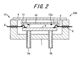
- Fig. 2 is a sectional view showing a fuel reforming apparatus 20A according to a second embodiment of the invention.
- parts corresponding to configuration according to the above-described embodiment will be denoted by the same reference numerals so that descriptions thereof will be omitted.
- the fuel reforming apparatus 20A includes a base, an external lead terminal 2, a lid body 4, a supply pipe 5a, a discharge pipe 5b, an insulating sealing material 8, a fuel reformer 9 having an electrode 7, a gas adsorbent 10, and a lead terminal 12a.
- a fuel reformer housing container 11 is configured so as to house the fuel reformer 9 by using the base 1, the lid body 4, the supply pipe 5a, and the discharge pipe 5b. In the fuel reformer housing container 11, the fuel reformer 9 and the gas adsorbent 10 are housed, and a concave portion of the base 1 is hermetically sealed with the lid body 4, thus resulting in the fuel reforming apparatus 20A.
- the lead terminal 12a is configured in the same manner as the lead terminal 12 according to the above-described embodiment, except that the lead terminal 12a is provided in a through-hole formed in a side wall which is different from a side wall having the penetrating external lead terminal 2, among four side walls having inner surfaces defining the concave portion of the base 1.
- the gas adsorbent 10 is placed and fixed directly on the inner surface defining the concave portion of the base 1, the principal surface of the lid body 4 facing the base 1, or the surface of the fuel reformer 9. Further, as shown in Fig. 2, the gas adsorbent 10 may be placed and fixed on the inner surface defining the concave portion of the base 1, the principal surface of the lid body 4 facing the base 1, or the surface of the fuel reformer 9 by way of a pedestal 13 formed of ceramic, metal, or resin. Moreover, the gas adsorbent 10 may be fixed only on the lead terminal 12 and disposed so as to be distanced away from the base 1, the lid body 4, or the fuel reformer 9.
- the gas adsorbent 10 carries out evacuation by using gas adsorption effected by chemically-active metal powder.
- the gas adsorbent 10 is fabricated by making one surface or both surfaces of the metal plate formed of Ni-Cr or the like ingredient having a thickness of around 10 to 500 ⁇ m carry metal powder containing Zr, Fe, V, or the like component as chief constituents, which metal powder will have a thickness of 10 ⁇ m to 1 mm.
- the profile is preferably set to have the same size as that of the fuel reformer 9 so that the gas adsorbent 10 can absorb the radiant heat emitted from the fuel reformer 9.
- the lead terminal 12a is attached to the gas adsorbent 10 by the spot welding or the like method.
- the gas adsorbent 10 is energized through the lead terminal 12a and thereby heated to be activated.
- the gas adsorbent is heated at a temperature of 350 to 900°C, thus resulting in a nearly 100%-activated state.
- the activation means that in a production process, the removal of the oxide film formed on the surface of the gas adsorbent 10 causes a new gas-adsorbing surface to appear so that the gas adsorbent 10 is given a function of adsorbing gas such as CO, N 2 , and H 2 existing in its surrounding area.
- adsorbing gas such as CO, N 2 , and H 2 existing in its surrounding area.
- the temperature and time for the activation are varied depending on a sort of metal powder in use.
- the gas adsorbent 10 be disposed so as to face a high-temperature portion of the fuel reformer 9 so that the gas adsorbent 10 is more easily activated by absorbing the radiant heat emitted from the fuel reformer 9. It is desired especially that the gas adsorbent 10 be disposed near the temperature adjusting mechanism formed in the fuel reformer 9, e.g. a heater portion composed of a resistive layer and the like.
- gas adsorbent 10 is placed on the principal surface of the lid body 4 facing the base 1, the gas adsorbent 10 may be placed on the inner surface defining the concave portion of the base 1 or the surface of the fuel reformer 9. Furthermore, the adsorbent 10 may be placed in a gap between the fuel reformer 9 and a bottom plate of the concave portion of the base 1, or in a gap between the fuel reformer 9 and a side surface of the concave portion of the base 1.
- Fig. 3 is a sectional view showing a fuel reforming apparatus 20B according to a third embodiment of the invention.
- parts corresponding to configurations according to the above-described embodiments will be denoted by the same reference numerals so that descriptions thereof will be omitted.
- the fuel reforming apparatus 20B includes a base 1, an external lead terminal 2, a lid body 4, a supply pipe 5a, a discharge pipe 5b, an insulating sealing material 8, a fuel reformer 9 having an electrode 7, and a gas adsorbent 10.
- a fuel reformer housing container 11 is configured so as to house the fuel reformer 9 by using the base 1, the lid body 4, the supply pipe 5a, and the discharge pipe 5b.
- the fuel reformer 9 and the gas adsorbent 10 are housed, and a concave portion of the base 1 is hermetically sealed with the lid body 4, thus resulting in the fuel reforming apparatus 20B.
- the adsorbent 10 is provided on the surface of the fuel reformer 9.
- the gas adsorbent 10 is formed of chemically-active metal powder containing Zr, Fe, V, or the like component as chief constituents, and carries out evacuation by using the gas adsorption, and is provided on the surface of the fuel reformer 9.
- providing the gas adsorbent 10 on the fuel reformer 9 leads the reduction in transmission of the radiant heat from the fuel reformer 9 to the base 1 and the lid body 4, thus allowing the gas adsorbent 10 to keep activated by the heat emitted from the fuel reformer 9 to thus remain further high in gas adsorbing ability, and at the same time, the temperature of the surface of the fuel reformer housing container 11 can be more effectively prevented from rising.
- the electrode 7 on the fuel reformer 9 and the external lead terminal 2 are electrically connected to each other via the bonding wire 3, or alternatively, the electrode 7 and the external lead terminal 2 are electrically connected to each other directly. Furthermore, the concave portion of the base 1 is sealed by the use of the lid body 4, thereby forming the fuel reforming apparatus 20B that hermetically seals the fuel reformer 9 housed in the concave portion of the base 1.
- the fuel reformer 9 is housed in the fuel reformer housing container 11 in a manner that the lid body 4 is attached to the base 1 so as to cover the concave portion of the base 1 by joining them using a metallic brazing material such as Au alloy, Ag alloy, and A1 alloy or a glass material, or by resistance welding, etc.
- a metallic brazing material such as Au alloy, Ag alloy, and A1 alloy or a glass material, or by resistance welding, etc.
- the fuel reforming apparatus 11 is heated over all in order to activate the gas adsorbent 10, or alternatively, the gas adsorbent 10 is heated by the heat of the fuel reformer 9.
- the gas adsorbent is heated at a temperature of 350 to 900°C, thus resulting in a nearly 100%-activated state.
- the gas adsorbent 10 is provided on the surface of the fuel reformer 9 as described above, but it is preferable that the gas adsorbent 10 be joined to the fuel reformer 9 via a metal plate or metal layer formed of Ni-Cr or the like ingredient. This is because the interposition of the metal plate or metal layer leads to reinforcement of the bonding strength between the gas adsorbent 10 and the fuel reformer 9, and gives the metal plate or metal layer the heat released from the fuel reformer 9, which heat can be used to activate the gas adsorbent 10 evenly, so that the electric power for heating the gas adsorbent 10 can be reduced and the efficiency of power generation of the fuel cell system can be enhanced.
- the gas adsorbent 10 by forming a high-resistive metal plate or metal layer of Ni-Cr or the like and applying the electric current to the metal plate or metal layer so that the metal plate or metal layer generates heat.
- the gas adsorbent 10 be fabricated by making one surface or both surfaces of the metal plate having a thickness of around 10 to 500 ⁇ m carry the metal powder which will have a thickness of 10 ⁇ m to 1 mm.
- the metal plate is preferably selected to have the same size as that of the fuel reformer 9 so that the metal plate can adsorb the radiant heat emitted from the fuel reformer 9.
- the gas adsorbent 10 is mounted by the spot welding or the like method.
- the gas adsorbent 10 be disposed so as to face the high-temperature portion of the fuel reformer 9 so that the gas adsorbent 10 is more easily activated by absorbing the radiant heat emitted from the fuel reformer 9.
- the gas adsorbent 10 be disposed on a heat-generating portion of the fuel reformer 9. This allows the gas adsorbent 10 to more effectively cut off conduction of the heat which is emitted from the heat-generating portion such as a thin film heater and a thick film heater formed in the fuel reformer 9 adapted to release a larger amount of heat and which is directed to the base 1 and the lid body 4, and moreover it is also possible to favorably rise the temperature of the gas adsorbent 10.
- gas adsorbent 10 is placed on the surface of the base 1 in an example shown in Fig. 3, the gas adsorbent 10 may be placed on the inner surface of the concave portion of the base 1 or the surface of the fuel reformer 9. Furthermore, the adsorbent 10 may be placed in a gap between the fuel reformer 9 and the bottom plate of the concave portion of the base 1, or in a gap between the fuel reformer 9 and the side surface of the concave portion of the base 1.
- Fig. 4 is a sectional view showing a fuel reforming apparatus 20C according to a fourth embodiment of the invention.
- parts corresponding to configurations according to the above-described embodiments will be denoted by the same reference numerals so that descriptions thereof will be omitted.
- the fuel reforming apparatus 20C includes a base 1, an external lead terminal 2, a lid body 4, a supply pipe 5a, a discharge pipe 5b, an insulating sealing material 8, a fuel reformer 9 having an electrode 7, a gas adsorbent 10, and a lead terminal 12.
- a fuel reformer housing container 11 is configured so as to house the fuel reformer 9 by using the base 1, the lid body 4, the supply pipe 5a, and the discharge pipe 5b.
- the fuel reformer 9 and the gas adsorbent 10 are housed, and a concave portion of the base 1 is hermetically sealed with the lid body 4, thus resulting in the fuel reforming apparatus 20C.
- the fuel reforming apparatus 20C according to the present embodiment is similar to the configuration of the fuel reforming apparatus 20 according to the first embodiment. It is notable that the inner pressure of the concave portion is set at 10 2 Pa or less. Further, the fuel reforming apparatus 20C according to the embodiment is different from the fuel reforming apparatus 20 according to the first embodiment in that the lead terminal 12 is provided on the base 1 without the insulating sealing material 8 interposed therebetween.
- the inner pressure of the concave portion is set at 10 2 Pa or less. Accordingly, the heat released from the fuel reformer 9 can be effectively prevented from being conducted to the base 1 and the lid body 4.
- the inner pressure of the concave portion exceeding 10 2 Pa causes the heat to be more easily conducted to the base 1 and the lid body 4 by the heat released from the fuel reformer 9, and moreover causes the gas adsorbent 10 to be more easily autoactivated so that the gas adsorbent 10 is liable to deteriorate in activity for a short time.
- the base 1 and the lid body 4 are jointed to each other by the welding method such as the projection method, the seam welding method, the electronic beam method, or the laser beam method.
- the welding method such as the projection method, the seam welding method, the electronic beam method, or the laser beam method.
- the gas adsorbent 10 is thus not activated upon sealing the fuel reforming apparatus 11.
- the base 1 and the lid body 4 be joined to each other by the welding method under a lower pressure of 10 2 Pa or less in order to prevent the adsorbing property of the gas adsorbent 10 from deteriorating.
- the joining operation under a pressure exceeding 10 2 Pa may cause the gas adsorbent 10 to be autoactivated by reaction heat upon adsorbing the gas around the gas adsorbent 10, resulting in progress of the activation which may cause the deterioration of the adsorbing property.
- a larger amount of the gas adsorbent 10 is required for decreasing the inner pressure of the fuel reformer housing container 11 to increase the level of vacuum inside the fuel reformer housing container 11, with the result that the amount of the gas adsorbent 10 may exceed a set acceptable amount of gas adsorbent inside the fuel reformer housing container 11.
- the joint between the base 1 and the lid body 4 and its neighbor area may be oxidized during the welding operation, which may possibly cause the outgas to be released from the oxidized areas by influences of a temperature in reforming the fuel and as time passes.
- the fuel reformer 9 is formed so that the electrode 7 on the fuel reformer 9 is electrically connected to the external lead terminal 2 disposed on the base 1 via the bonding wire 3. Consequently, the heater formed on the surface of and inside the fuel reformer 9 can be heated through the electrode 7. As a result, the reaction temperature can be maintained in the fuel reformer 9, thus allowing the fuel-reforming reaction to be stabilized.
- the gas adsorbent 10 is heated in a manner that electric energy is transmitted by the lead terminal from an external power source to a metal material inside the gas adsorbent so that the metal material generates heat, or in a manner that light such as infrared light or laser light is emitted to the gas adsorbent 10 through a window portion provided on the lid body 4 and the base 1 so that energy of the light is converted into thermal energy directly by the gas adsorbent 10.
- the gas adsorbent 10 may be mounted on the inner surface defining the concave portion of the base 1 directly or via a pedestal, or may be mounted on the fuel reformer 9. Further, as shown in Fig. 4, the gas adsorbent may be connected to the led terminal which then transmits the electric energy from the external power source, and the electric energy may be then transmitted to the metal plate of the gas adsorbent 10 where the electric energy is converted into the thermal energy to thereby secondarily heat the gas adsorbent 10.
- gas adsorbent 10 is joined to the lead terminal 12 in an example shown in Fig. 4, the gas adsorbent 10 may be joined to an insulating pedestal made of ceramic.
- Fig. 5 is a sectional view showing a fuel reforming apparatus 20D according to a fifth embodiment of the invention.
- Fig. 6 is a perspective view showing the fuel reforming apparatus 20D of Fig. 5 seen from the top.
- Fig. 7 is a perspective view showing the fuel reforming apparatus 20D of Fig. 5 seen from the bottom.
- Fig. 8 is a perspective view showing a base 1A in the fuel reforming apparatus 20D of Fig. 5.
- parts corresponding to configurations according to the above-described embodiments will be denoted by the same reference numerals so that descriptions thereof will be omitted.
- the fuel reforming apparatus 20D includes a base 1A, an external lead terminal 2, a lid body 4A, a supply pipe 5a, a discharge pipe 5b, an insulating sealing material 8, a fuel reformer 9 having an electrode 7, a gas adsorbent 10, and a lead terminal 12.
- a fuel reformer housing container 11 is configured so as to house the fuel reformer 9 by using the base 1A, the lid body 4A, the supply pipe 5a, and the discharge pipe 5b.
- the fuel reformer 9 is housed in the fuel reformer housing container which is hermetically sealed with the lid body 4A and the base 1A, thus resulting in the fuel reforming apparatus 20D.
- Both of the base 1A and the lid body 4A in the invention have a role as a container that houses the fuel reformer 9. They are made of, for example, metal materials such as Fe-based alloys including stainless steel, Fe-Ni-Co alloy, and Fe-Ni alloy, or oxygen free copper; inorganic materials; organic materials; or a complex of these ingredients. Note that the concave portion formed in the base 1A may be formed by joining a frame body to the base 1A, or alternatively the concave portion may be formed directly in the base 1A.
- a grove 15 for discharging the gas inside the concave portion is formed in at least one of a joint between the base 1A and the lid body 4A and a joint between the lid body 4A and the base 1A.
- Fig. 8 shows an example in which the groove 15 is formed in a joint surface of the base 1A to the lid body 4A, the configuration is not limited thereto and the groove 15 may be formed in a joint surface of the lid body 4A to the base 1A.
- a joint of the base 1A to the lid body 4A is formed so as to protrude all around the circumference, and this protruded part (generally, the protruded part is also referred to as a projection.
- This protruded part will be also referred to a projection hereinbelow.) 14 is partially notched to thereby form the groove 15. Accordingly, when the lid body 4A and the base 1A are joined to each other by the welding method with the heat generated only in the joint of the lid body 4A to the base 1A, it is possible to concentrate the heat on the projection 14, resulting in an increase in joint efficiency.
- the heat can be effectively prevented from being transmitted to the base 1A or the lid body 4A so that the other components in the fuel reformer housing container 11 or the other components disposed outside the fuel reformer housing container 11 will not be impaired and so that the fuel reformer housing container 11 will not be strained, resulting in no defective sealing.
- the base 1A and the lid body 4A as described above are formed into predetermined shapes by a cutting method, a pressing method, an MIM (Metal Injection Mold) method or the like method.
- a width of the groove 15 of the projection 14 formed in at least one of the base 1A and the lid body 4A be 0.05 mm to 5 mm. This makes it possible to exhaust the air inside the fuel reformer housing container 11 and to carry out the hermetic sealing at the sealing occasion under the depressurized state. As a result, the heat transmitted from the fuel reformer 9 to the base 1A and the lid body 4A can be effectively reduced so that the temperature of the fuel reformer 9 can be prevented from decreasing to thus reduce the power generation loss and moreover, the temperature of the fuel reformer housing container 11 can be more effectively prevented from rising.
- the base 1A and the lid body 4A it is desirable to apply to surfaces of the base 1A and the lid body 4A a plating treatment with Au or Ni, a coating treatment such as resin coating which uses polyimide and the like resin, or the like treatment.
- a plating treatment with Au or Ni a coating treatment such as resin coating which uses polyimide and the like resin, or the like treatment.
- the thickness is approximately 0.1 to 5 ⁇ m.
- the base 1A and the lid body 4A as described above should be formed thin, of which mechanical strength, i.e. a bending strength is preferably 200 MPa or more.
- the lid body 4A and the base 1A be each made of a metal material of which thermal conductivity is 120 W/mK or less. Accordingly, the heat emitted from the fuel reformer 9 can be prevented from being conducted to the lid body 4A and the base 1A so that the temperatures of the surface of lid body 4A and the surface of base 1A can be more effectively prevented from rising. It is thus possible to more effectively prevent the other components inside the fuel reformer housing container 11 and the other components outside the fuel reformer housing container 11 from being impaired so that the fuel cell system can be used stably and safely for a long period of time.
- the metal material of which thermal conductivity is 120 W/mK or less include, for example, stainless steel, Fe-Ni-Co alloy, and Fe-Ni alloy.
- the electrode 7 on the fuel reformer 9 and the external lead terminal 2 are electrically connected to each other, and the lid body 4A and the base 1A are joined to each other, thereby forming the fuel reforming apparatus 20D which hermetically seals the fuel reformer 9 housed in the fuel reformer housing container 11.
- the base 1A and the lid body 4A are joined to each other by welding or the like method, and at the welding occasion, an inner surface defining the groove 15 is fused to close the groove 15.
- the welding methods such as resistance welding or welding effected by laser irradiation, a brazing method, etc.
- the welding is made to proceed while the internal gas is discharged by way of the groove 15, and when the welding finally reaches the vicinity of the groove 15, the welding causes the inner surface defining the groove 15 to be fused, thereby closing the groove 15.
- a brazing material is previously applied to a part except the groove 15, and after the brazing material is wet and spread between the base 1A and the lid body 4A, the brazing material is finally spread over the groove 15, thereby closing the groove 15.
- the brazing material may be previously applied to also the inner surface defining the groove 15. In this case, it is necessary to secure a sufficient passage for exhausting the gas existing in the groove 15 so that the groove 15 is not closed upon the joining occasion.
- the groove 15 is closed at the end so that the gas in the fuel reformer housing container 11 can be favorably exhausted by the groove 15.
- the base 1A and the lid body 4A are joined to each other by welding, and the inner surface defining the groove 15 is fused upon joining the base 1A and the lid body 4A so that the groove 15 is closed.
- This makes it possible to generate heat only on the joint between the lid body 4A and the base 1A so that the lid body 4A and the base 1A are joined to each other. Further, the heat is prevented from being transmitted to the base 1A or the lid body 4A so that the other components inside the fuel reforming apparatus 20D or the other components outside the fuel reforming apparatus 20D will not be impaired and so that the fuel reformer housing container 11 will not be strained, resulting in no defective sealing.
- the lid body 4A and the base 1A are welded in a manner that a part except the groove 15 is welded earlier and the groove 15 is closed at the end while the exhaustion is carried out by the groove 15, with the result that the groove 15 can be prevented from being filled during the welding and the efficiency of exhaust can be thus prevented from decreasing, resulting in a higher level of vacuum inside the fuel reformer housing container 11.
- the fuel reformer 9 is electrically connected to the external lead terminal 2 by connecting the electrode 7 on the fuel reformer 9 to the external lead terminal 2 provided on the base 1A. This makes it possible to heat a heater formed on the surface of and inside the fuel reformer 9 through the electrode 7. As a result, the reaction temperature can be maintained in the fuel reformer 9 so that the fuel-reforming reaction can be stabilized.
- the gas adsorbent 10 is disposed along the inner surface defining the concave portion near the groove 15. Accordingly, the groove 15 is used for exhausting the air upon joining the base 1A and the lid body 4A to each other, and the gas adsorbent 10 is brought close to the part defining the groove 15 to which the air is liable to be deposited when the groove 15 is being closed, thus allowing the air deposited on the part defining the groove 15 to be efficiently adsorbed by the gas adsorbent 10 promptly.
- the efficiency of adsorbing the gas can be increased to a very high level by preventing a vicious circle such that the air deposited on the part defining the groove 15 is released into the fuel reformer housing container and then deposited again on the other parts.
- the inner pressure of the fuel reformer housing container 11, that is, the inner pressure of the concave portion is preferably set at 10 2 Pa or less.
- the base 1A and the lid body 4A are joined to each other by the resistance welding method.
- the welding method only the joint between the base 1A and the lid body 4A and its neighbor are heated. Accordingly, the gas adsorbent 10 can be prevented from being heated and is never activated upon sealing the fuel reformer housing container 11.
- the base 1A and the lid body 4A be joined to each other under a pressure of 10 2 Pa or less. Joining the base 1A and the lid body 4A under the pressure of 10 2 Pa or less makes it possible to increase the level of vacuum inside the fuel reformer housing container 11. It is thus possible to effectively prevent the heat from being transmitted from the fuel reformer 9 to the base 1A and the lid body 4A.
- the gas adsorbent 10 can be effectively prevented from being autoactivated by the reaction heat generated upon adsorbing the gas around the gas adsorbent 10 which usually results in progress of the activation causing the deterioration of the adsorbing property. Further, when the inner pressure is decreased and the level of vacuum is increased in the fuel reformer housing container, the gas adsorbent 10 can be effectively prevented from having its acceptable gas-adsorbing amount approaching to the limit so that the adsorbing function of the gas adsorbent 10 can be favorably maintained.
- the outgas released into the fuel reformer housing container after the fuel reformer housing container is hermetically sealed means gas adsorbed on surfaces of various components inside the fuel reformer housing container such as the inner surface of the fuel reformer housing container or the surface of the fuel reformer itself, or gas released from the joint between the base 1A and the lid body 4A and a part surrounding the joint which are oxidized at the welding occasion, by influences of a temperature in reforming the fuel and as time passes.
- the level of vacuum inside the fuel reformer housing container 11 can be enhanced further by sealing the fuel reformer housing container under the pressure of 10 2 Pa or less and thereafter absorbing the outgas by the gas adsorbent 10.
- the supply pipe 5a and the discharge pipe 5b may penetrate the base 1A or the lid body 4A.
- the supply pipe 5a and the discharge pipe 5b may be nipped in a joining interface between the base 1A and the lid body 4A to thereby communicate the inside of the concave portion with outside thereof.
- gas adsorbent 10 is joined to the lead terminal 12 in an example shown in Fig. 5, the adsorbent 10 may be fixed on an insulating pedestal made of, for example, ceramic.
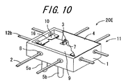
- Fig. 9 is a sectional view showing a fuel reforming apparatus 20E according to a sixth embodiment of the invention.
- Fig. 10 is perspective view showing the fuel reforming apparatus 20E of Fig. 9 seen from the top, having a part of the lid body 4 taken out.
- Fig. 11 is a perspective view showing the fuel reforming apparatus 20E of Fig. 9'seen from the bottom.
- Fig. 12 is an enlarged plan view showing a part of the gas adsorbent 10 in the fuel reforming apparatus 20E of Fig. 9.
- Fig. 13 is a perspective view showing a fuel reforming apparatus 20F according to a seventh embodiment of the invention, having a part of the lid body 4 taken out.
- Fig. 14 is an enlarged plane view showing a part of the gas adsorbent 10 in the fuel reforming apparatus 20F of Fig. 13.
- the fuel reforming apparatus 20E includes a base 1, an external lead terminal 2, a lid body 4A, a supply pipe 5a, a discharge pipe 5b, an insulating sealing material 8, a fuel reformer 9 having an electrode 7, a gas adsorbent 10, and a lead terminal 12b.
- a fuel reformer housing container 11 is configured so as to house the fuel reformer 9 by using the base 1, the lid body 4, the supply pipe 5a, and the discharge pipe 5b.
- the fuel reformer 9 and the gas adsorbent 10 are housed in the fuel reformer housing container 11 of which concave portion is hermetically sealed with the lid body 4, thus resulting in the fuel reforming apparatus 20E.
- the lead terminal 12b is configured in the same manner as the lead terminal 12 according to the above-described embodiment, except that the lead terminal 12b is provided in a through-hole formed in a side wall which is different from a side wall having the penetrating external lead terminal 2, among four side walls having inner surfaces defining the concave portion of the base 1, and the lead terminal 12b is provided in the base 1 by way of the insulating sealing material 8.
- the gas adsorbent 10 enhances the level of vacuum by using gas adsorption effected by chemically-active metal powder.
- the gas adsorbent 10 is fabricated by making one surface or both surfaces of the belt-like metal plate formed of Ni-Cr or the like ingredient having a thickness of, for example, around 10 to 500 ⁇ m carry metal powder containing Zr, Fe, V, or the like component as chief constituents, which metal powder will have a thickness of 10 ⁇ m to 1 mm.
- the gas adsorbent 10 is attached by the spot welding or the like method to the lead terminal 12b fixed on the base 1 or the lid body 4 so as to communicate the inside of the concave portion of the base 1 with outside thereof.
- the lead terminal 12b serves for the energization of the metal plate of the gas adsorbent 10.
- the metal particle deposited on the surface of the metal plate can be heated and thus activated by the lead terminal 12b and the metal plate which generates resistance heat in the energization.
- the lead terminals 12b are respectively connected to both ends of the gas adsorbent 10, and a voltage is applied between the lead terminals 12b connected to the both ends, thereby allowing the gas adsorbent 10 to be energized.
- a high-resistance portion 16 is formed in a part of an energized portion in the metal plate constituting the gas adsorbent 10, the high-resistance portion 16 of which sectional area cut in a direction orthogonal to an energizing direction is smaller than those of the other parts.
- the energized portion of the metal plate indicates a part which carries a current inputted and outputted by the lid terminal 12b electrically connected to the metal plate for energizing the metal plate, that is, a part which is located between the lead terminal 12b for current input and the lead terminal 12b for current output in the metal plate.
- a part having high resistance is formed locally in the metal plate, and the part having high resistance efficiently generates heat to thereby allow the metal powder deposited on the surface of the metal plate to be activated at a high efficiency, so that a value of current applied for activation of the gas adsorbent 10 can be decreased.
- the electric power for heating the gas adsorbent 10 can be reduced, and the efficiency of power generation of the fuel cell system using the fuel reformer housing container 11 can be enhanced.
- the gas adsorbent 10 can be activated efficiently by the high-resistance portion 16, and it is therefore possible to maintain a gas adsorbing function which is sufficient for maintaining the favorable vacuum state inside the fuel reformer housing container 11 even with a smaller gas adsorbent 10. Accordingly, a space for housing the gas adsorbent 10 can be reduced in size so that the fuel reformer housing container 11 can be smaller in size and lower in height and furthermore, the fuel cell system equipment for mobile device using the fuel reformer housing container 11 can be smaller in size and lower in height.
- the high-resistance portion 16 only needs to be formed so that a sectional area thereof cut in a direction orthogonal to the energizing direction of the metal plate is smaller than those of the other parts.
- the high-resistance portion 16 is therefore formed by various methods such as to form a notch 16a crossing the energizing direction in the metal plate and to form a thinner metal plate.
- the high-resistance portion 16 be formed by providing the notch 16a as shown in Fig. 12 on the energized portion of the metal plate. Accordingly, even in the case where the gas adsorbent 10 is deformed due to influences of the heat generated in the activation through the energization effected by the lead terminal 12b connected to the gas adsorbent 10, the notch 16a can reduce the deformation and prevent the stress from arising in the connection between the gas adsorbent 10 and the lead terminal 12b. As a result, it is possible to effectively prevent the connection between the lead terminal 12b and the gas adsorbent 10 from being damaged, and to effectively prevent the gas adsorbent 10 from falling off from the lead terminal 12b.
- a shape of the notch 16a provided in the metal plate of the gas adsorbent 10 may vary, including a V shape, a square shape, and a round shape.
- the notch 16a may be formed in one part as shown in Figs. 10 and 12 while the notches 16a may be formed in plural parts as in the case of the fuel reforming apparatus 20F according to the seventh embodiment of the invention shown in Figs. 13 and 14.
- the notch 16a is preferably provided at a middle portion of the gas adsorbent 10 or at regular intervals over the full length of the gas adsorbent 10 so that the heat generated from the notch 16a in the energization can be transmitted evenly to the entire gas adsorbent 10.
- the gas adsorbent 10 having the notch 16a is shaped by a method of pressing a metal plate made of Ni-Cr and the like ingredient carrying metal powder containing Zr, Fe, V, and the like ingredient as chief constituents, into a predetermined shape; a cutting method using laser or the like means; or a method in which the metal plate made of Ni-Cr and the like ingredient that has been previously processed into a predetermined shape by the above method and thereafter is made to carry the metal powder containing Zr, Fe, V, and the like ingredient as chief constituents.
- the gas adsorbent 10 is disposed so as to face the fuel reformer 9, and the notch 16a is disposed so as to face the fuel reformer 9.
- the heat of the gas adsorbent 10 can be radiated to the fuel reformer 9 by moving the notch 16a of the gas adsorbent 10, which generates a particularly large amount of heat, close to the fuel reformer 9, and can thus contribute to an increase in temperature of the fuel reformer 9 so that the electric power being supplied for maintaining the high temperature of the fuel reformer 9 can be reduced.
- the efficiency of power generation of the fuel cell system using the fuel reformer housing container 11 can be further enhanced.
- Methods of forming the vacuum inside the fuel reformer housing container 11 include, for example, a method of sealing the fuel reformer housing container 11 by brazing the lid body 4 thereon in a vacuum furnace, or a method of welding the lid body 4 onto the fuel reformer housing container 11 in a vacuum furnace by using the seam welding method.
- the gas adsorbent 10 is energized through the lead terminal 12 and thereby heated and activated.
- the gas adsorbent 10 is heated at a temperature of 350 to 900°C, thus resulting in a nearly 100%-activated state.
- gas adsorbent 10 may be fixed only on the lead terminal 12b and disposed so as to be distanced away from the base 1, the lid body 4, or the fuel reformer 9.
- the present example shows the metal plate of the gas adsorbent 10 having a platy shape as shown in Figs. 10 and 13.
- the shape of the metal plate of the gas adsorbent 10 is not limited to the platy shape, and may be columnar or may have a bent part.
- the notch 16a having a groove shape may be formed in the metal plate.
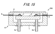
- Fig. 15 is a sectional view showing a fuel reforming apparatus 20G according to an eighth embodiment of the invention.
- parts corresponding to configurations according to the above-described embodiments will be denoted by the same reference numerals so that descriptions thereof will be omitted.
- the fuel reforming apparatus 20G includes a base 1, an external lead terminal 2, a lid body 4A, a supply pipe 5a, a discharge pipe 5b, an insulating sealing material 8, and a fuel reformer 9 having an electrode 7.
- a fuel reformer housing container 11 is configured so as to house the fuel reformer 9 by using the base 1, the lid body 4, the supply pipe 5a, and the discharge pipe 5b.
- the fuel reformer 9 is housed in the fuel reformer housing container 11, and a concave portion of the base 1 is hermetically sealed with the lid body 4, thus resulting in the fuel reforming apparatus 20G.
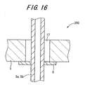
- Fig. 16 is an enlarged sectional view of chief part showing the joint between the supply pipe 5a or discharge pipe 5b and the base 1 in the fuel forming apparatus 20G of Fig. 15.
- Figs. 15 and 16 is shown one example of embodiment of the supply pipe 5a or the discharge pipe 5b in which a flange portion 6 is provided outside.
- the supply pipe 5a or the discharge pipe 5b is joined to the base 1 or the lid body 4 so as to have the air gap 17 between the base 1 or lid body 4 and the through-hole formed in the base 1 or lid body 4.
- the air gap 17 as described above can be formed between an outer surface of the supply pipe 5a or discharge pipe 5b and an inner surface of the through-hole by joining the flange portion 6 to a peripheral portion of the through-hole of the base 1 or lid body 4 in the case where the supply pipe 5a or discharge pipe 5b has the flange portion 6 as shown in Figs. 15 and 16, for example.
- Fig. 17 is an enlarged sectional view of chief part showing a joint between a supply pipe 5a or discharge pipe 5b and a base 1 in a fuel forming apparatus 20H according to a ninth embodiment of the invention.
- an air gap 17 may be formed by joining only a part of an outer surface of the supply pipe 5a or discharge pipe 5b to an inner surface of a through-hole of the base 1 or lid body 4 by way of a brazing material or a sealing material 18.
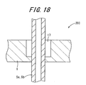
- Fig. 18 is an enlarged sectional view of chief part showing a joint between a supply pipe 5a or discharge pipe 5b and a base 1 in a fuel forming apparatus 20I according to a tenth embodiment of the invention.
- an air gap 17 may be formed by providing a step in a through-hole of the base 1 or lid body 4 and then joining the supply pipe 5a or discharge pipe 5b to the step through brazing, welding, or the like method.
- a width of the air gap 17 between the outer surface of the supply pipe 5a or discharge pipe 5b and the inner surface of the through-hole of the base 1 or lid body 4 is preferably set at 0.01 mm or more.
- the width of the air gap 17 is preferably set at 0.01 to 0.3 mm.
- the width of the air gap 17 which is shorter than 0.01 mm may cause the supply pipe 5a or discharge pipe 5b to come into contact with the inner surface of the through-hole when the supply pipe 5a or discharge pipe 5b is inserted into the base 1 or lid body 4, and moreover make it difficult to secure the air gap 17 by the brazing material such as Au-Sn and Ag-Cu which fills the air gap 17 between the supply pipe 5a or discharge pipe 5b and the through-hole attributable to the capillarity.
- the heat generated by the fuel reformer 9 is transmitted from the supply pipe 5a or discharge pipe 5b to the base 1, thus leading an increase in a temperature of a surface of outer wall of the fuel reformer housing container 11, which causes the other components inside the mobile equipment to be more easily broken.
- the width of the air gap 17 which is longer than 0.3 mm makes it difficult to braze the supply pipe 5a or discharge pipe 5b on the inner surface of the through-hole of the base 1 or lid body 4.
- the width of the air gap 17 between the outer surface of the supply pipe 5a or discharge pipe 5b and the inner surface of the through-hole of the base 1 or lid body 4 is set at preferably 0.01 mm or more and more preferably 0.01 to 5mm.
- the width of the air gap 17 which is shorter than 0.01 mm may cause the supply pipe 5a or discharge pipe 5b to come into contact with the inner surface of the through-hole when the supply pipe 5a or discharge pipe 5b is inserted into the base 1 or lid body 4, and moreover make it difficult to secure the air gap 17 by the brazing material such as Au-Sn and Ag-Cu which fills the air gap 17 between the supply pipe 5a or discharge pipe 5b and the through-hole attributable to the capillarity.
- the heat generated by the fuel reformer 9 is transmitted from the supply pipe 5a or discharge pipe 5b to the base 1, thus leading an increase in the temperature of the surface of outer wall of the fuel reformer housing container 11, which causes the other components inside the mobile equipment to be more easily broken.
- the width of the air gap 17 which is longer than 5 mm tends to make the flange portion 6 larger, with the result that the deformation of the flange portion 6 and the like tend to be generated more easily. Further, also the fuel reformer housing container 11 itself is liable to be larger, thus posing impediments for the decrease in size and height.
- an outer diameter of the flange portion 6 is preferably set to be longer than a diameter of the through-hole of the base 1 and lid body 4 into which the supply pipe 5a or discharge pipe 5b is inserted, by 1 mm or more, from the perspective of works such as brazing or welding or for the purpose of preventing the flange portion 6 from being deformed. Further, it is preferred that a thickness of the flange portion 6 be set at 0.1 mm or more in order to prevent its deformation. Moreover, the flange portion 6 of the supply pipe 5a or discharge pipe 5b is preferably provided with a projection all around the circumference in order to be joined to the base 1 by the welding method.
- flange portion 6 is directly joined to the supply pipe 5a or discharge pipe 5b in the example shown in Figs. 15 and 16, it is possible to use a tubular member in communication with the supply pipe 5a or discharge pipe 5b, of which section has a circular shape or a multangular shape and which is provided with the flange portion 6 and joined to the base 1 or lid body 4.
- a fuel reformer housing container comprises a base having a concave portion for housing a fuel reformer in which reformed gas containing hydrogen gas is generated from fuel; a discharge pipe for communicating inside of the concave portion with outside thereof to discharge the reformed gas from the fuel reformer; a supply pipe for communicating inside of the concave portion with outside thereof to supply the fuel to the fuel reformer; a lid body joined to the base so as to cover the concave portion of the base; and a gas adsorbent housed in the concave portion, for adsorbing gas in the concave portion.
- the gas adsorbed to an inner surface of the fuel reformer housing container or surfaces of various components inside the fuel reformer housing container such as a surface of the fuel reformer itself is released, after the fuel reformer housing container is sealed by the lid body, as outgas inside the fuel reformer housing container by influences of a temperature in reforming the fuel and as time passes, the gas can be favorably adsorbed by the gas adsorbent. It is therefore possible to maintain a vacuum state inside the fuel reformer housing container not only for a short period just after sealing the fuel reformer housing container 11 in which the fuel reformer 9 is housed, but also for a long period thereafter.
- the gas adsorbent is disposed between the fuel reformer and an inner surface of the concave portion or between the fuel reformer and the lid body so that the gas adsorbent is adjacent to or in contact with the fuel reformer. Consequently, the heat emitted from the fuel reformer can contribute to a rise in temperature of the gas adsorbent, thus activating the gas adsorbent, so that electric power for heating the gas adsorbent can be reduced and an efficiency of power generation of the fuel cell system can be enhanced.
- the gas adsorbent can adsorb the heat which is conducted from the fuel reformer to the base and the lid body so that temperatures of a surface of lid body and a surface of base can be more effectively prevented from rising. It is thus possible to more effectively prevent the other components inside a mobile equipment from being broken so that the fuel cell system can be used stably and safely for a long period of time.
- a fuel-reforming reaction is an endothermic reaction such as a steam-reforming reaction as expressed by the chemical reaction formula (1)
- a temperature of the fuel reformer does not decrease, with the result that the need of increasing an amount of power generation of a heater is eliminated, resulting in no increase in power generation loss of the entire fuel cell system.
- a high-efficient fuel cell system can be achieved.
- a distance between the gas adsorbent and the discharge pipe is set to be shorter than a distance between the gas adsorbent and the supply pipe. Consequently, the heat of the discharge pipe which has a high temperature attributable to reformed gas having a high temperature shortly after reformed by the fuel reformer, ca be utilized for activation of the gas adsorbent, with the result that the electric power for heating the gas adsorbent can be reduced, and moreover, a vacuum state inside the power generation loss fuel reformer housing container can be favorably maintained.
- the fuel reformer housing container further includes a lead terminal which is attached onto the base so as to be led from inside of the concave portion to outside, and the gas adsorbent is fixed on the lead terminal while securing a distance from the base. Consequently, the heat of the gas adsorbent can be effectively prevented from being conducted to the base, and the temperature of the gas adsorbent can be thus effectively prevented from decreasing so that the gas adsorbent can be maintained at a high temperature, with the result that electric power for heating the gas adsorbent can be reduced and the efficiency of power generation of the fuel cell system can be enhanced.
- the gas adsorbent is formed by depositing metal powder on a surface of a metal plate, and moreover, a lead terminal serving for energization of the gas adsorbent is provided so as to communicate the inside of the concave portion with outside thereof.
- a lead terminal serving for energization of the gas adsorbent is provided so as to communicate the inside of the concave portion with outside thereof.
- On an energized portion of the metal plate is provided a high-resistance portion of which sectional area cut in a direction orthogonal to an energizing direction is smaller than sectional areas of other parts.
- the high-resistance portion efficiently generates heat to thereby allow the metal powder deposited on its surface to be activated at a high efficiency, so that a value of current applied for activation of the gas adsorbent can be decreased.
- the electric power for heating the gas adsorbent can be reduced, and the efficiency of power generation of the fuel cell system using the fuel reformer housing container can be enhanced.
- the gas adsorbent can be activated efficiently by the high-resistance portion, and it is therefore possible to maintain a gas adsorbing function which is sufficient for maintaining the favorable vacuum state inside the fuel reformer housing container even with a smaller gas adsorbent. Accordingly, a space for housing the gas adsorbent can be reduced in size so that the fuel reformer housing container can be smaller in size and lower in height and furthermore, the fuel cell system equipment for mobile device using the fuel reformer housing container can be smaller in size and lower in height.
- the high-resistance portion is formed by providing a notch in the energized portion of the metal plate. Consequently, even in the case where the gas adsorbent is deformed due to influences of the heat generated in the activation through the energization effected by a lead terminal connected to the gas adsorbent, the notch can reduce the deformation and prevent stress from arising in the connection between the gas adsorbent and the lead terminal. As a result, it is possible to effectively prevent the connection between the lead terminal and the gas adsorbent from being damaged, and to effectively prevent the gas adsorbent from falling off from the lead terminal.
- the gas adsorbent is disposed so as to face the fuel reformer, and the notch is provided so as to face the fuel reformer. Consequently, the heat of the gas adsorbent can be radiated to the fuel reformer by moving the notch of the gas adsorbent, which generates a particularly large amount of heat, close to the fuel reformer, and can thus contribute to an increase in temperature of the fuel reformer so that the electric power being supplied for maintaining the high temperature of the fuel reformer can be reduced. As a result, the efficiency of power generation of the fuel cell system using the fuel reformer housing container can be further enhanced.
- a groove for discharging the gas inside the concave portion is formed on at least one of a joint of the base to the lid body and a joint of the lid body to the base. Consequently, it is possible to sufficiently discharge the gas existing in the fuel reformer housing container from the groove when the lid body and the base are joined to each other in a depressurized state, thus exhausting the air existing in the fuel reformer housing container so that a high vacuum can be formed inside the fuel reformer housing container.
- At least one of a joint of the base to the lid body and a joint of the lid body to the base is formed so as to protrude all around, and the groove is formed by notching a part of the protruded portion. Consequently, when the lid body and the base are joined to each other by the welding method with the heat generated only in the joint of the lid body to the base, it is possible to concentrate the heat on the projection, resulting in an increase in joint efficiency. At the same time, the heat can be effectively prevented from being transmitted to the base or the lid body so that the other components in the fuel reformer housing container or the other components disposed outside the fuel reformer housing container will not be impaired and so that the fuel reformer housing container will not be strained, resulting in no defective sealing.
- the gas adsorbent is disposed along an inner surface defining the concave portion near the groove. Consequently, the groove is used for exhausting the air upon joining the base and the lid body to each other, and the gas adsorbent is brought close to the groove portion to which the air is liable to be deposited when the groove is being closed, thus allowing the air deposited on the groove portion to be efficiently adsorbed by the gas adsorbent promptly. That is to say, the efficiency of adsorbing the gas can be increased to a very high level by preventing a vicious circle such that the air deposited on the groove portion is released into the fuel reformer housing container and then deposited again on the other parts.
- the lid body and the base are made of a metal material of which thermal conductivity is 120 W/mK or less. Consequently, the heat emitted from the fuel reformer can be prevented from being conducted to the lid body and the base so that the temperatures of the surface of lid body and the surface of base can be more effectively prevented from rising. It is thus possible to more effectively prevent the other components inside the fuel reformer housing container and the other components outside the fuel reformer housing container from being impaired so that the fuel cell system can be used stably and safely for a long period of time.
- the above-described fuel reformer housing container of the invention and the fuel reformer housed in the concave portion are provided, thus achieving a fuel cell system which is stable, safe, and highly efficient for a long period of time.
- the gas adsorbent is provided on a surface of the fuel reformer, with the result that the gas adsorbent can be maintained at a high temperature by utilizing the heat of the fuel reformer also after the gas adsorbent has been activated by the heat of the fuel reformer.
- the gas adsorbent can be used in a state where the gas adsorption efficiency is very high, with the result that the vacuum state inside the fuel reforming apparatus can be maintained not only for a short period just after sealing the fuel reforming apparatus in which the fuel reformer is housed, but also for a long period thereafter.
- the gas adsorbent and the fuel reformer are joined to each other via a metal plate. Consequently, a bonding strength between the gas adsorbent and the fuel reformer can be reinforced, and moreover, the heat released from the fuel reformer can be given to the metal plate, which heat can be used to activate the gas adsorbent evenly, so that the electric power for heating the gas adsorbent can be reduced and the efficiency of power generation of the fuel cell system can be enhanced.
- the gas adsorbent is disposed on a heat-generating portion of the fuel reformer. Consequently, the gas adsorbent can be heated directly by the heat-generating portion, with the result that the electric power required for heating the gas adsorbent can be further reduced, and moreover, the vacuum state inside the power generation loss fuel reforming apparatus can be maintained more favorably.
- an inner pressure of the concave portion is 10 2 Pa or less. Consequently, the heat radiation from the fuel reformer can be prevented from causing the heat to be transmitted to the base and the lid body. Moreover, there is set a state where the level of vacuum around the gas adsorbent is increased so that the gas adsorbent deteriorates in activity, with the result that slight heat generated upon joining the base and the lid body can be effectively prevented from causing the gas adsorbent to be autoactivated so that the adsorbing property will not approach saturation.
- the lid body and the base are joined to each other by using any one of a projection method, a seam welding method, an electronic beam method, and a laser beam method. Consequently, only the joint between the base and the lid body and its neighbor area are heated, and it is thus possible to effectively prevent the heat from being transmitted from the joint between the base and the lid body to the gas adsorbent through the lid body so that the gas adsorbent will not be activated. This makes it possible to prevent the gas adsorbent from adsorbing the gas around the gas adsorbent upon attaching the lid body so that the adsorbing property will not approach the saturation and the deterioration of activity will not occur.
Abstract
An object of the invention is to provide a fuel reformer housing container and a fuel reforming apparatus, which are capable of maintaining a level of vacuum inside the fuel reformer housing container favorably and which have less power generation loss. A fuel reformer housing container (11) includes a base (1) having a concave portion for housing a fuel reformer (9) in which reformed gas containing hydrogen gas is generated from fuel, a discharge pipe (5b) for communicating inside of the concave portion with outside thereof to discharge the reformed gas from the fuel reformer, a supply pipe (5a) for communicating inside of the concave portion with outside thereof to supply the fuel to the fuel reformer (9), and a gas adsorbent (10) housed in the concave portion, for adsorbing gas in the concave portion.
Description
- The present invention relates to a fuel reformer housing container for constituting a fuel reforming apparatus using a fuel reformer that generates hydrogen gas from a variety of fuels, for example, in a fuel cell system, and also relates to a fuel reforming apparatus.
- In recent years, a fuel cell system has been in the limelight as a next-generation power source system that produces electric energy efficiently and cleanly, and in automobile market and in market of electric power co-generation system typified by a household fuel cell power generation system, field tests for practical implementation aiming at cost reduction have been already executed energetically.
- Besides, it has been examined recently to miniaturize the fuel cell system and use as a power source of mobile equipment such as a mobile phone, a PDA (Personal Digital Assistant), a notebook computer, a digital video camera and a digital still camera.
- Generally, in a fuel cell, power generation is performed in a manner that hydrocarbon gas such as methane or natural gas (CNG) or alcohol such as methanol or ethanol is used as fuel which is then reformed to hydrogen gas and other gas in a fuel reforming apparatus using a fuel reformer, and thereafter the hydrogen gas is supplied to a power generation apparatus referred to as a power generation cell.
- In this case, the fuel reforming in the fuel reformer indicates a process of generating hydrogen gas by a catalytic reaction.
- For example, in the case of using methanol as fuel, there are some reactions for reforming the fuel, one of which indicates, for example, a process of generating hydrogen gas (H2) by a steam-reforming reaction as expressed by the following chemical reaction formula (1) (a reaction of bonding steam to methanol and thereby, reforming methanol to hydrogen and carbon dioxide in the formula (1)). Note that a minute amount of generated gas (mainly CO2) other than hydrogen generated by the reforming reaction is usually discharged into the air.
CH3OH + H2O → 3H2 + CO2 (1)
- Since the steam-reforming reaction as described above is an endothermic reaction, it is necessary to provide a heater or the like outside for heating the fuel reformer so that a reaction temperature is maintained. Therefore, for reforming the fuel in the fuel reformer, in order to prevent a steam-reforming activity of catalyst from lowering and keep the density of produced hydrogen gas high, a temperature of approximately 200 to 500°C is required in the case of using methanol as fuel, and a high temperature around 300 to 800°C is required in the case of using methane gas, for example.
- Further, in a partial oxidation-reforming reaction as expressed by the following chemical reaction formula (2), for example, a reforming temperature around 400 to 600°C is required.
CH3OH + 1/2O2 + 2N2 → 2H2 + CO2 + 2N2 (2)
- In view of the foregoing, in the cogeneration power generation system typified by the household fuel cell system, considering that the system itself is large, an outer wall of the fuel reformer housing container is formed into a double-layered structure to thus constitute a vacuum container, or, alternatively, a gap between an inner wall and an outer wall of the double-layered structure is filled up with insulation, to thereby prevent heat inside the fuel reformer from being conducted to outside so that the temperature of the fuel reformer will not decrease. Accordingly, upon housing the fuel reformer into the fuel reformer housing container, it is possible to join the fuel reformer directly to the inner wall of the double-layered structure of the fuel reformer housing container so that the fuel reformer can be placed and fixed in the fuel reformer housing container.
- As a related art, there is
Japanese Unexamined Patent Publication JP-A 2003-2602 - In recent years, a fuel cell system for use in a mobile equipment has been demanded to be smaller in size and lower in height in order to be housed in the mobile equipment. However, the conventional outer wall of the fuel reformer housing container formed into the double-layered structure is not adoptable in the fuel cell system for use in the mobile equipment because the fuel cell system becomes complicated and larger in size overall. For the fuel cell system for use in the mobile equipment, there has been thus proposed a fuel cell system with a fuel reformer housing container composed of a base having a concave portion and a lid body, of which inner part is formed in a vacuum state to cut off the outward conduction of heat generated in reforming the fuel inside the fuel reformer, resulting in small power generation loss.
- In order to use the fuel cell system as described above stably and safely for a long period of time, the vacuum state inside the fuel reformer housing container needs to be maintained not only for a short period just after sealing the fuel reformer housing container in which the fuel reformer is housed, but also for a long period thereafter. However, after sealing the fuel reformer housing container by the lid body, the gas adsorbed to an inner surface of the fuel reformer housing container and surfaces of various components inside the fuel reformer housing container such as a surface of the fuel reformer itself may possibly be released as outgas inside the fuel reformer housing container by influences of a temperature in reforming the fuel and as time passes.
- In this case, the level of vacuum inside the fuel reformer housing container drops, thus leading an increase in an amount of outward conduction of heat generated in reforming the fuel inside the fuel reformer, with the result that a temperature of the fuel reformer housing container rises by the heat, which may break other components inside the mobile equipment.
- Further, in the case where the fuel-reforming reaction is an endothermic reaction such as the steam-reforming reaction as expressed by the chemical reaction formula (1), the fuel reforming in the fuel reformer requires a heater or the like for heating the fuel reformer so that a reaction temperature is maintained at a constant level, but the heat generated in the fuel reformer is conducted to the fuel reformer housing container as described above, thus causing the temperature of the fuel reformer to be more easily decreased.
- In view of the foregoing, the amount of power generation of the heater needs to be increased in order to maintain the reaction temperature, but the increase in the power generation of the heater leads an increase in electric capacity which is used for heating the heater, relative to the total electric capacity generated in the power generation cell of the fuel cell, resulting in a problem that the power generation loss in the entire fuel cell system increases.
- The invention has been completed in consideration of the above-stated problems in the related art, and an object of the invention is to provide a fuel reformer housing container and a fuel reformer which are capable of maintaining a level of vacuum inside the fuel reformer housing container favorably and which have less power generation loss.
- The invention provides a fuel reformer housing container comprising:
- a base having a concave portion for housing a fuel reformer in which reformed gas containing hydrogen gas is generated from fuel;
- a discharge pipe for communicating inside of the concave portion with outside thereof to discharge the reformed gas from the fuel reformer;
- a supply pipe for communicating inside of the concave portion with outside thereof to supply the fuel to the fuel reformer;
- a lid body joined to the base so as to cover the concave portion of the base; and
- a gas adsorbent housed in the concave portion, for adsorbing gas in the concave portion.
- In the invention, it is preferable that the gas adsorbent is disposed between the fuel reformer and an inner surface defining the concave portion or between the fuel reformer and the lid body so that the gas adsorbent is adjacent to or in contact with the fuel reformer.
- In the invention, it is preferable that a distance between the gas adsorbent and the discharge pipe is set to be shorter than a distance between the gas adsorbent and the supply pipe.
- In the invention, it is preferable that the fuel reformer housing container further comprises a lead terminal which is attached onto the base so as to be led from inside of the concave portion to outside, and the gas adsorbent is fixed on the lead terminal inside the concave portion while securing a distance from the base.
- In the invention, it is preferable that the gas adsorbent is formed by depositing metal powder on a surface of a metal plate, a lead terminal serving for energization of the gas adsorbent is provided so as to communicate the inside of the concave portion with outside thereof, and a part of energized portion of the metal plate is provided with a high-resistance portion of which sectional area cut in a direction orthogonal to an energizing direction is smaller than sectional areas of other parts.
- In the invention, it is preferable that the high-resistance portion is formed by providing a notch in the energized portion of the metal plate.
- In the invention, it is preferable that the gas adsorbent is disposed so as to face the fuel reformer, and the notch is provided so as to face the fuel reformer.
- In the invention, it is preferable that a groove for discharging gas inside the concave portion is formed on at least one of a joint of the base to the lid body and a joint of the lid body to the base.
- In the invention, it is preferable that at least one of the joint of the base to the lid body and the joint of the lid body to the base is formed so as to protrude all around, and the groove is formed by notching a part of the protruded portion.
- In the invention, it is preferable that the gas adsorbent is disposed along an inner surface defining the concave portion near the groove.
- In the invention, it is preferable that the lid body and the base are made of a metal material of which thermal conductivity is 120 W/mK or less.
- The invention provides a fuel reforming apparatus comprising the above-described fuel reformer housing container and a fuel reformer housed in the concave portion.
- In the invention, it is preferable that the gas adsorbent is provided on a surface of the fuel reformer.
- In the invention, it is preferable that the gas adsorbent and the fuel reformer are joined to each other via a metal plate.
- In the invention, it is preferable that the gas adsorbent is disposed on a heat-generating portion of the fuel reformer.
- In the invention, it is preferable that an inner pressure of the concave portion is 102 Pa or less.
- In the invention, it is preferable that the lid body and the base are joined to each other by any one of a projection method, a seam welding method, an electronic beam method, and a laser beam method.
- Objects, features, and advantages of the invention will be more explicit from the following detailed description taken with reference to the drawing wherein:
- Fig. 1 is a sectional view showing a fuel reforming apparatus according to a first embodiment of the invention;
- Fig. 2 is a sectional view showing a fuel reforming apparatus according to a second embodiment of the invention;
- Fig. 3 is a sectional view showing a fuel reforming apparatus according to a third embodiment of the invention;
- Fig. 4 is a sectional view showing a fuel reforming apparatus according to a fourth embodiment of the invention;
- Fig. 5 is a sectional view showing a fuel reforming apparatus according to a fifth embodiment of the invention;
- Fig. 6 is a perspective view showing the fuel reforming apparatus of Fig. 5 seen from the top;
- Fig. 7 is a perspective view showing the fuel reforming apparatus of Fig. 5 seen from the bottom;
- Fig. 8 is a perspective view showing a base in the fuel reforming apparatus of Fig. 5;
- Fig. 9 is a sectional view showing a fuel reforming apparatus according to a sixth embodiment of the invention;
- Fig. 10 is perspective view showing the fuel reforming apparatus of Fig. 9 seen from the top, having a part of a lid body taken out;
- Fig. 11 is a perspective view showing the fuel reforming apparatus of Fig. 8 seen from the bottom;
- Fig. 12 is an enlarged plan view showing a part of a gas adsorbent in the fuel reforming apparatus of Fig. 9;
- Fig. 13 is a perspective view showing a fuel reforming apparatus according to a seventh embodiment of the invention, having a part of a lid body taken out;
- Fig. 14 is an enlarged plane view showing a part of a gas adsorbent in the fuel reforming apparatus of Fig. 13;
- Fig. 15 is a sectional view showing a fuel reforming apparatus according to an eighth embodiment of the invention;
- Fig. 16 is an enlarged sectional view of chief part showing a joint between a supply pipe or discharge pipe and a base in the fuel forming apparatus of Fig. 15;
- Fig. 17 is an enlarged sectional view of chief part showing a joint between a supply pipe or discharge pipe and a base in a fuel forming apparatus according to a ninth embodiment of the invention; and
- Fig. 18 is an enlarged sectional view of chief part showing a joint between a supply pipe or discharge pipe and a base in a fuel forming apparatus according to a tenth embodiment of the invention.
- Now referring to the drawings, preferred embodiments of the invention are described below.
- Fig. 1 is a sectional view showing a
fuel reforming apparatus 20 according to a first embodiment of the invention. Thefuel reforming apparatus 20 includes abase 1, anexternal lead terminal 2 serving as a wiring for supplying electric power to a fuel reformer, alid body 4, asupply pipe 5a serving as a supplying passage for supplying fuel, adischarge pipe 5b serving as a discharging passage for discharging reformed gas, an insulatingsealing material 8, afuel reformer 9, agas adsorbent 10, and alead terminal 12 on which thegas adsorbent 10 is fixed. The insulatingsealing material 8 seals through-holes of thebase 1, in which theexternal lead terminal 2 and thelead terminal 12 are fixed and insulated. A fuelreformer housing container 11 is configured so as to house thefuel reformer 9 by using thebase 1, thelid body 4, thesupply pipe 5a, and thedischarge pipe 5b. In the fuelreformer housing container 11, thefuel reformer 9 and thegas adsorbent 10 are housed, and a concave portion of thebase 1 is hermetically sealed with thelid body 4, thus resulting in thefuel reforming apparatus 20. - Both of the
base 1 and thelid body 4 of the invention have a role as a container that houses thefuel reformer 9. Thebase 1 and thelid body 4 are made of, for example, metal materials such as Fe-based alloy including stainless steel, Fe-Ni-Co alloy, and Fe-Ni alloy, or oxygen free copper; aluminum oxide (Al2O3) sintered body; mullite (3Al2O3·2SiO2) sintered body; silicon carbide (SiC) sintered body; aluminum nitride (A1N) sintered body; or silicon nitride (Si3N4) sintered body; a ceramic material including glass ceramic; and a highly heat-resistant resin material including polyimide. - Note that the glass ceramic applicable to the
base 1 and thelid body 4 is formed of a glass component and a filler component. Examples of the glass component include SiO2-B2O3, SiO2-B2O3-Al2O3, SiO2-B2O3-Al2O3-MO (M represents Ca, Sr, Mg, Ba or Zn), SiO2-Al2O3-M1O-M2O (M1 and M2 are the same or different, and represent Ca, Sr, Mg, Ba or Zn), SiO2-B2O3-Al2O3-M1O-M2O (M1 and M2 are as described above), SiO2-B2O3-M3 2O (M3 represents Li, Na or K), SiO2-B2O3-Al2O3-M3 2O (M3 is as described above), Pb glass, and Bi glass. - Further, examples of the filler component include a composite oxide of Al2O3, SiO2, ZrO2 and an alkaline earth metal oxide, a composite oxide of TiO2 and an alkaline earth metal oxide, and a composite oxide (for example, spinel, mullite, and cordierite) containing at least one selected from the group consisting of Al2O3 and SiO2.
- To take an example, the
base 1 and thelid body 4 are made of a compact aluminum oxide sintered body whose relative density is 95% or more. In this case, thebase 1 and thelid body 4 are fabricated as follows. For example, to begin with, a sintering aid such as rare-earth oxide powder and aluminum oxide powder is added to aluminum oxide powder which is then mixed so that powder of raw material of the aluminum oxide sintered body is prepared. Next, an organic binder and a dispersion medium are added to the powder of raw material which is then mixed into paste to be processed by a doctor blade method. Alternatively, an organic binder is added to the powder of raw material which is then processed by press molding, rolling molding or the like method so that a green sheet having a predetermined thickness is produced. Then, a predetermined number of sheet-shaped products are aligned, laminated and bonded by pressure, and a thusobtained laminated product is thereafter fired, for example, at a firing maximum temperature of 1200 to 1500°C in a non-oxidative atmosphere. In this way, thebase 1 and thelid body 4 made of ceramic are obtained as aimed. Thebase 1 and thelid body 4 may be formed by a powder mold pressing method. - To take another example, in a case where the
base 1 and thelid body 4 are made of metal materials, a cutting method, a pressing method, an MIM (Metal Injection Mold) method, or the like method is used to form a predetermined shape. - Further, in the case where the
base 1 and thelid body 4 are made of metal materials, it is desirable to apply to the surfaces of thebase 1 and thelid body 4, for example, a plating treatment with Au or Ni, or a coating treatment such as resin coating which uses polyimide and the like resin, in order to prevent corrosion. For example, in the case of Au plating treatment, it is desired that its thickness be approximately 0.1 to 5 µm. - In order to make the fuel
reformer housing container 11 be smaller in size and lower in height, thebase 1 and thelid body 4 as described above should be formed thin, of which mechanical strength, i.e. a bending strength is preferably 200 MPa or more. - Next, it is preferred that the
external lead terminal 2 and thelead terminal 12 be made of metals whose thermal expansion coefficients are equal or approximate to those of thebase 1 andlid body 4. For example, theexternal lead terminal 2 made of Fe-Ni alloy and thelead terminal 12 made of Fe-Ni-Co alloy can prevent thermal strain caused in response to a temperature change in practical implementation. Besides, favorable sealing adhesions can be obtained between theexternal lead terminal 2 and thebase 1 and between thelead terminal 12 and thebase 1, and it is moreover possible to secure an excellent bonding property, a strength necessary for implementation, and favorable soldering property and welding property. - Further, the insulating
sealing material 8 is made of, for example, a glass material such as borosilicate glass, alkali glass, and insulation glass whose chief constituent is lead, and a ceramic material such as aluminum oxide. In through-holes formed in thebase 1, the insulatingsealing material 8 achieves the electrical insulation between thebase 1 and theexternal lead terminal 2 and between thebase 1 and thelead terminal 12 while theexternal lead terminal 2 and thelead terminal 12 are sealed and fixed. The through-holes formed in thebase 1, through which theexternal lead terminal 2 and thelead terminal 12 are inserted, each need to have such a size as to prevent mutual contact which causes the electric conduction between thebase 1 and theexternal lead terminal 2 and between thebase 1 and thelead terminal 12. To be specific, the through-hole needs to have such an inner diameter to secure a gap of 0.1 mm or more from theexternal lead terminal 2 or lead terminal 12 to thebase 1. - Note that, in a case where the insulating
sealing material 8 is made of a ceramics material such as aluminum oxide, theexternal lead terminal 2 and thelead terminal 12 are inserted into the through-holes of thebase 1 with a cylindrical insulating sealingmaterial 8 made of the ceramic material interposed between theexternal lead terminal 2 and lead terminal 12 and thebase 1. In this case, it is possible to use a brazing material such as Au-Ge and Ag-Cu for connecting the insulatingsealing material 8 to thebase 1, connecting the insulatingsealing material 8 to theexternal lead terminal 2, and connecting the insulatingsealing material 8 to thelead terminal 12. - The
electrode 7 on thefuel reformer 9 and theexternal lead terminal 2 are electrically connected to each other via thebonding wire 3. Furthermore, the concave portion of thebase 1 is sealed by the use of thelid body 4, thereby forming a fuel reforming apparatus that hermetically seals thefuel reformer 9 housed in the concave portion of the fuelreformer housing container 11. - The
fuel reformer 9 housed in the fuelreformer housing container 11 according to the invention is a device for reforming fuel, having therein a fine flow channel or air gap which carries a catalyst for reforming fuel. - The
fuel reformer 9 is various in shape and may have, for example, a substantially square shape which is used as a minute chemical device, for example, having a liquid fluid channel fabricated by using a semiconductor production technique to form a thin groove in a base material, for example, made of an inorganic material such as semiconductor like silicon, silica, glass, metal, and ceramic by means of a cutting method, an etching method, a blast method, or the like method, and a glass plate or a cover made of metal etc. is then closely attached to the surface by anodic bonding, brazing, welding, or the like method for the purpose of prevention of evaporation of a fluid in operation. Further, thefuel reformer 9 may have a tubular shape formed of an inorganic material such as silica, glass, metal, and ceramic, which carries a catalyst therein for reforming fuel. - In a case where a fuel-reforming reaction is an endothermic reaction such as a steam-reforming reaction, inside the
fuel reformer 9 is formed a temperature adjusting mechanism such as a thin film heater (not shown) or a thick film heater (not shown) composed of a resistance layer or the like component, and on a surface of thefuel reformer 9 is formed theelectrode 7 as a terminal that supplies electric power to the heater. With the temperature adjusting mechanism, the temperature of thefuel reformer 9 is adjusted to approximately 200 to 800°C of which temperature condition corresponds to a fuel reforming condition, so that the fuel supplied from a fuel supply port to which thesupply pipe 5a is connected is brought to react with steam, thus allowing favorable acceleration in the reforming action for generating hydrogen gas from thedischarge pipe 5b connected to a fuel discharge port. - The heater as described above is disposed inside or near the flow channel or air gap in the
fuel reformer 9, which carries a catalyst to perform the fuel reforming. The heat being generated from the heater can be thus used efficiently for the fuel-reforming reaction. - The
fuel reformer 9 is housed in the fuelreformer housing container 11 in a manner that thelid body 4 is attached to thebase 1 so as to cover the concave portion of thebase 1 by joining them using a metallic brazing material such as Au alloy, Ag alloy, and A1 alloy or a glass material, or by a seam welding method, etc. - For example, in the case of using an Au-Sn brazing material for the joining, the Au-Sn brazing material is welded to the
lid body 4 in advance, or alternatively, the Au-Sn brazing material formed into a frame-shape by a punching processing or the like method using a die etc. is placed between thebase 1 and thelid body 4, and thereafter, thelid body 4 is joined to thebase 1 in a sealing furnace or a seam welder, with the result that thefuel reformer 9 can be sealed in the fuelreformer housing container 11. - Further, the
fuel reformer 9 is formed so that theelectrode 7 on thefuel reformer 9 is electrically connected to theexternal lead terminal 2 disposed on thebase 1 via thebonding wire 3. Consequently, the heater formed on the surface of or inside thefuel reformer 9 can be heated through theelectrode 7. As a result, the reaction temperature can be maintained in thefuel reformer 9, thus allowing the fuel-reforming reaction to be stabilized. - The
supply pipe 5a and thedischarge pipe 5b are respectively a supplying passage for a raw material or a fuel gas fluid and a discharging passage for reformed gas containing hydrogen. Thesupply pipe 5a and thedischarge pipe 5b are each made of, for example, a metal material such as Fe-Ni alloy, Fe-Ni-Co alloy, and stainless steel, a ceramic material such as Al2O3 sintered body, 3Al2O3·2SiO2 sintered body, SiC sintered body, A1N sintered body, Si3N4 sintered body and glass ceramic sintered body, a resin material having high heat resistance such as polyimide, or glass. - It is preferred that the
supply pipe 5a and thedischarge pipe 5b be each made of a material which is hard to be embrittled by hydrogen contained in reformed gas. Such a material includes Fe alloy, ceramic, and glass. - In the fuel reformer housing container of the invention, the
gas adsorbent 10 for adsorbing gas in the concave portion is preferably housed in the concave portion. Consequently, even when the gas adsorbed to the inner surface of the fuel reformer housing container or the surfaces of various components inside the fuel reformer housing container such as the surface of thefuel reformer 9 itself is released, after sealed by thelid body 4, as outgas inside the fuelreformer housing container 11 by influences of a temperature in reforming the fuel and as time passes, the gas can be favorably adsorbed by thegas adsorbent 10 and therefore, it is possible to maintain the vacuum state inside the fuelreformer housing container 11 not only for a short period just after sealing the fuelreformer housing container 11 in which thefuel reformer 9 is housed, but also for a long period thereafter. - The
gas adsorbent 10 carries out evacuation by using gas adsorption effected by chemically-active metal powder. Thegas adsorbent 10 is fabricated by making one surface or both surfaces of the metal plate formed of Ni-Cr or the like ingredient having a thickness of around 10 to 500 µm carry metal powder containing Zr, Fe, V, or the like component as chief constituents, which metal powder will have a thickness of 10 µm to 1 mm. - Note that the surface of the metal powder of the
gas adsorbent 10 is usually covered with an oxide film and therefore, such a surface remaining intact as it is exerts no gas adsorption. The metal powder of thegas adsorbent 10 is thus subjected to a heating process so that the oxide film on the surface of the adsorbent spreads into the adsorbent to then cause a new active surface to appear, thus initiating (activating) the gas adsorption. - Accordingly, the
gas adsorbent 10 is attached to thelead terminal 12 by a spot welding method or the like method at a position distanced away from thebase 1 and thelid body 4 and thus fixed inside the fuelreformer housing container 11. That is to say, thegas adsorbent 10 is in a state of being suspended from thebase 1 and thelid body 4 so that the heat of thegas adsorbent 10 can be effectively prevented from being conducted to thebase 1 and thelid body 4. - In order to provide the fuel
reformer housing container 11 with the heat insulating property, it is necessary to form a vacuum inside the fuelreformer housing container 11. Upon sealing thefuel reformer 9, it is appropriate to carry out the sealing by using the brazing material in a vacuum furnace, or by the seam welding method in a vacuum chamber. - Subsequently, the
gas adsorbent 10 is energized through thelead terminal 12 so that the metal plate of thegas adsorbent 10 is heated to thereby have the metal powder of thegas adsorbent 10 activated. - The activation condition for the
gas adsorbent 10 is varied depending on a sort of metal powder. The activated state can be obtained by heating thegas adsorbent 10 at a temperature of around 350 to 900°C. - Further, it is desired especially that the
gas adsorbent 10 be disposed near the temperature adjusting mechanism formed in thefuel reformer 9, e.g. a heater portion composed of a resistive layer and the like, so that thegas adsorbent 10 is more easily activated by absorbing the radiant heat emitted from thefuel reformer 9. - Furthermore, in order to reduce the heat transmission from the
fuel reformer 9 to thebase 1 and thelid body 4, it is preferred that thegas adsorbent 10 be disposed adjacent to or in contact with thefuel reformer 9 between thefuel reformer 9 and the inner surface defining the concave portion or between thefuel reformer 9 and thelid body 4. This allows thegas adsorbent 10 to keep activated by the heat emitted from thefuel reformer 9 to thus remain high in gas adsorbing ability, and at the same time, the temperature of the surface of the fuelreformer housing container 11 can be more effectively prevented from rising. - Herein, the layout of the
gas adsorbent 10 being disposed adjacent to thefuel reformer 9 means that a distance between thegas adsorbent 10 and thefuel reformer 9 is shorter than a distance between thegas adsorbent 10 and the inner surface defining thebase 1, or that a distance betweengas adsorbent 10 and thefuel reformer 9 is shorter than a distance between thegas adsorbent 10 and a principal surface of thelid body 4 facing thebase 1. More preferably, thegas adsorbent 10 is in contact with thefuel reformer 9, or a distance between thegas adsorbent 10 and thefuel reformer 9 is 5 mm or less. This allows the heat emitted from thefuel reformer 9 to effectively contribute to rise of the temperature of thegas adsorbent 10. - As a layout example of the
gas adsorbent 10, in a case where thefuel reformer 9 has a substantially square shape, it is desired that thegas adsorbent 10 be disposed so as to face a principal surface of thefuel reformer 9. This allows thegas adsorbent 10 to effectively cut off conduction of the heat which is emitted from the principal surface offuel reformer 9 adapted to release a larger amount of heat and which is directed to thebase 1 and thelid body 4, and moreover it is also possible to favorably rise the temperature of thegas adsorbent 10. - Further, in a case where the
fuel reformer 9 has a tubular shape which is bent on one plane, it is desired that thegas adsorbent 10 be disposed so as to face the one plane in parallel therewith. This allows thegas adsorbent 10 to face many parts of thefuel reformer 9 so that the heat which is conducted to thebase 1 and thelid body 4 can be effectively cut off at thegas adsorbent 10, and moreover it is also possible to favorably rise the temperature of thegas adsorbent 10. - Further, it is preferred that in the fuel
reformer housing container 11 of the invention, a distance between thegas adsorbent 10 and thedischarge pipe 5b be set to be shorter than a distance between thegas adsorbent 10 and thesupply pipe 5a. Accordingly, the reformed gas has a high temperature shortly after reformed by thefuel reformer 9, and the heat of thedischarge pipe 5b which has a high temperature attributable to such high-temperature gas can be utilized for the activation of thegas adsorbent 10, with the result that the electric power for heating thegas adsorbent 10 can be reduced, and moreover, the vacuum state inside the power generation loss fuelreformer housing container 11 can be favorably maintained. - Note that although the
lead terminal 12 which fixes thegas adsorbent 10 is inserted and thus attached to thebase 1 in an example shown in Fig. 1, thelead terminal 12 may be inserted and thus attached to thelid body 4. - Fig. 2 is a sectional view showing a
fuel reforming apparatus 20A according to a second embodiment of the invention. In the present embodiment, parts corresponding to configuration according to the above-described embodiment will be denoted by the same reference numerals so that descriptions thereof will be omitted. - The
fuel reforming apparatus 20A includes a base, anexternal lead terminal 2, alid body 4, asupply pipe 5a, adischarge pipe 5b, an insulatingsealing material 8, afuel reformer 9 having anelectrode 7, agas adsorbent 10, and alead terminal 12a. A fuelreformer housing container 11 is configured so as to house thefuel reformer 9 by using thebase 1, thelid body 4, thesupply pipe 5a, and thedischarge pipe 5b. In the fuelreformer housing container 11, thefuel reformer 9 and thegas adsorbent 10 are housed, and a concave portion of thebase 1 is hermetically sealed with thelid body 4, thus resulting in thefuel reforming apparatus 20A. Thelead terminal 12a is configured in the same manner as thelead terminal 12 according to the above-described embodiment, except that thelead terminal 12a is provided in a through-hole formed in a side wall which is different from a side wall having the penetratingexternal lead terminal 2, among four side walls having inner surfaces defining the concave portion of thebase 1. - In the embodiment, the
gas adsorbent 10 is placed and fixed directly on the inner surface defining the concave portion of thebase 1, the principal surface of thelid body 4 facing thebase 1, or the surface of thefuel reformer 9. Further, as shown in Fig. 2, thegas adsorbent 10 may be placed and fixed on the inner surface defining the concave portion of thebase 1, the principal surface of thelid body 4 facing thebase 1, or the surface of thefuel reformer 9 by way of apedestal 13 formed of ceramic, metal, or resin. Moreover, thegas adsorbent 10 may be fixed only on thelead terminal 12 and disposed so as to be distanced away from thebase 1, thelid body 4, or thefuel reformer 9. - The
gas adsorbent 10 carries out evacuation by using gas adsorption effected by chemically-active metal powder. Thegas adsorbent 10 is fabricated by making one surface or both surfaces of the metal plate formed of Ni-Cr or the like ingredient having a thickness of around 10 to 500 µm carry metal powder containing Zr, Fe, V, or the like component as chief constituents, which metal powder will have a thickness of 10 µm to 1 mm. The profile is preferably set to have the same size as that of thefuel reformer 9 so that thegas adsorbent 10 can absorb the radiant heat emitted from thefuel reformer 9. Moreover, thelead terminal 12a is attached to thegas adsorbent 10 by the spot welding or the like method. - In order to provide the fuel
reformer housing container 11 with the heat insulating property, it is necessary to form a vacuum inside the fuelreformer housing container 11. Upon sealing thefuel reformer 9, it is appropriate to carry out the sealing by using the brazing material in a vacuum furnace, or by the seam welding method in a vacuum chamber. - Subsequently, the
gas adsorbent 10 is energized through thelead terminal 12a and thereby heated to be activated. As the activation condition, the gas adsorbent is heated at a temperature of 350 to 900°C, thus resulting in a nearly 100%-activated state. - The activation means that in a production process, the removal of the oxide film formed on the surface of the
gas adsorbent 10 causes a new gas-adsorbing surface to appear so that thegas adsorbent 10 is given a function of adsorbing gas such as CO, N2, and H2 existing in its surrounding area. The temperature and time for the activation are varied depending on a sort of metal powder in use. - It is preferred that the
gas adsorbent 10 be disposed so as to face a high-temperature portion of thefuel reformer 9 so that thegas adsorbent 10 is more easily activated by absorbing the radiant heat emitted from thefuel reformer 9. It is desired especially that thegas adsorbent 10 be disposed near the temperature adjusting mechanism formed in thefuel reformer 9, e.g. a heater portion composed of a resistive layer and the like. - Note that although the
gas adsorbent 10 is placed on the principal surface of thelid body 4 facing thebase 1, thegas adsorbent 10 may be placed on the inner surface defining the concave portion of thebase 1 or the surface of thefuel reformer 9. Furthermore, the adsorbent 10 may be placed in a gap between thefuel reformer 9 and a bottom plate of the concave portion of thebase 1, or in a gap between thefuel reformer 9 and a side surface of the concave portion of thebase 1. - Fig. 3 is a sectional view showing a
fuel reforming apparatus 20B according to a third embodiment of the invention. In the present embodiment, parts corresponding to configurations according to the above-described embodiments will be denoted by the same reference numerals so that descriptions thereof will be omitted. - The
fuel reforming apparatus 20B includes abase 1, anexternal lead terminal 2, alid body 4, asupply pipe 5a, adischarge pipe 5b, an insulatingsealing material 8, afuel reformer 9 having anelectrode 7, and agas adsorbent 10. A fuelreformer housing container 11 is configured so as to house thefuel reformer 9 by using thebase 1, thelid body 4, thesupply pipe 5a, and thedischarge pipe 5b. In the fuelreformer housing container 11, thefuel reformer 9 and thegas adsorbent 10 are housed, and a concave portion of thebase 1 is hermetically sealed with thelid body 4, thus resulting in thefuel reforming apparatus 20B. In the present embodiment, it is notable that the adsorbent 10 is provided on the surface of thefuel reformer 9. - The
gas adsorbent 10 is formed of chemically-active metal powder containing Zr, Fe, V, or the like component as chief constituents, and carries out evacuation by using the gas adsorption, and is provided on the surface of thefuel reformer 9. As described above, providing thegas adsorbent 10 on thefuel reformer 9 leads the reduction in transmission of the radiant heat from thefuel reformer 9 to thebase 1 and thelid body 4, thus allowing thegas adsorbent 10 to keep activated by the heat emitted from thefuel reformer 9 to thus remain further high in gas adsorbing ability, and at the same time, the temperature of the surface of the fuelreformer housing container 11 can be more effectively prevented from rising. - Further, the
electrode 7 on thefuel reformer 9 and theexternal lead terminal 2 are electrically connected to each other via thebonding wire 3, or alternatively, theelectrode 7 and theexternal lead terminal 2 are electrically connected to each other directly. Furthermore, the concave portion of thebase 1 is sealed by the use of thelid body 4, thereby forming thefuel reforming apparatus 20B that hermetically seals thefuel reformer 9 housed in the concave portion of thebase 1. - The
fuel reformer 9 is housed in the fuelreformer housing container 11 in a manner that thelid body 4 is attached to thebase 1 so as to cover the concave portion of thebase 1 by joining them using a metallic brazing material such as Au alloy, Ag alloy, and A1 alloy or a glass material, or by resistance welding, etc. - In order to provide the fuel
reformer housing container 11 with the heat insulating property, it is necessary to form a vacuum inside the fuelreformer housing container 11. In order to make the vacuum state, upon sealing thefuel reformer 9, it is appropriate to carry out the sealing by using the brazing material in a vacuum furnace or by the seam welding method, the electronic beam method, the projection method, etc. in a vacuum chamber, or alternatively, it is appropriate to carry out the sealing in advance by the seam welding method, the projection method, etc. in an inert atmosphere, and then perform vacuuming from a vacuuming pipe (not shown) formed in the fuelreformer housing container 11, followed by squashing the vacuuming pipe and then bonding under pressure, thus resulting in formation of the vacuum inside the fuelreformer housing container 11. - Subsequently, the
fuel reforming apparatus 11 is heated over all in order to activate thegas adsorbent 10, or alternatively, thegas adsorbent 10 is heated by the heat of thefuel reformer 9. As the activation condition, the gas adsorbent is heated at a temperature of 350 to 900°C, thus resulting in a nearly 100%-activated state. - Further, the
gas adsorbent 10 is provided on the surface of thefuel reformer 9 as described above, but it is preferable that thegas adsorbent 10 be joined to thefuel reformer 9 via a metal plate or metal layer formed of Ni-Cr or the like ingredient. This is because the interposition of the metal plate or metal layer leads to reinforcement of the bonding strength between thegas adsorbent 10 and thefuel reformer 9, and gives the metal plate or metal layer the heat released from thefuel reformer 9, which heat can be used to activate thegas adsorbent 10 evenly, so that the electric power for heating thegas adsorbent 10 can be reduced and the efficiency of power generation of the fuel cell system can be enhanced. Moreover, it is also possible to activate thegas adsorbent 10 by forming a high-resistive metal plate or metal layer of Ni-Cr or the like and applying the electric current to the metal plate or metal layer so that the metal plate or metal layer generates heat. - It is further preferred that the
gas adsorbent 10 be fabricated by making one surface or both surfaces of the metal plate having a thickness of around 10 to 500 µm carry the metal powder which will have a thickness of 10 µm to 1 mm. And the metal plate is preferably selected to have the same size as that of thefuel reformer 9 so that the metal plate can adsorb the radiant heat emitted from thefuel reformer 9. Moreover, thegas adsorbent 10 is mounted by the spot welding or the like method. - Further, it is more preferred that the
gas adsorbent 10 be disposed so as to face the high-temperature portion of thefuel reformer 9 so that thegas adsorbent 10 is more easily activated by absorbing the radiant heat emitted from thefuel reformer 9. - Further, it is desired that the
gas adsorbent 10 be disposed on a heat-generating portion of thefuel reformer 9. This allows thegas adsorbent 10 to more effectively cut off conduction of the heat which is emitted from the heat-generating portion such as a thin film heater and a thick film heater formed in thefuel reformer 9 adapted to release a larger amount of heat and which is directed to thebase 1 and thelid body 4, and moreover it is also possible to favorably rise the temperature of thegas adsorbent 10. - Note that although the
gas adsorbent 10 is placed on the surface of thebase 1 in an example shown in Fig. 3, thegas adsorbent 10 may be placed on the inner surface of the concave portion of thebase 1 or the surface of thefuel reformer 9. Furthermore, the adsorbent 10 may be placed in a gap between thefuel reformer 9 and the bottom plate of the concave portion of thebase 1, or in a gap between thefuel reformer 9 and the side surface of the concave portion of thebase 1. - Fig. 4 is a sectional view showing a fuel reforming apparatus 20C according to a fourth embodiment of the invention. In the present embodiment, parts corresponding to configurations according to the above-described embodiments will be denoted by the same reference numerals so that descriptions thereof will be omitted.
- The fuel reforming apparatus 20C includes a
base 1, anexternal lead terminal 2, alid body 4, asupply pipe 5a, adischarge pipe 5b, an insulatingsealing material 8, afuel reformer 9 having anelectrode 7, agas adsorbent 10, and alead terminal 12. A fuelreformer housing container 11 is configured so as to house thefuel reformer 9 by using thebase 1, thelid body 4, thesupply pipe 5a, and thedischarge pipe 5b. In the fuelreformer housing container 11, thefuel reformer 9 and thegas adsorbent 10 are housed, and a concave portion of thebase 1 is hermetically sealed with thelid body 4, thus resulting in the fuel reforming apparatus 20C. The fuel reforming apparatus 20C according to the present embodiment is similar to the configuration of thefuel reforming apparatus 20 according to the first embodiment. It is notable that the inner pressure of the concave portion is set at 102 Pa or less. Further, the fuel reforming apparatus 20C according to the embodiment is different from thefuel reforming apparatus 20 according to the first embodiment in that thelead terminal 12 is provided on thebase 1 without the insulatingsealing material 8 interposed therebetween. - In the fuel reforming apparatus 20C of the invention, the inner pressure of the concave portion is set at 102 Pa or less. Accordingly, the heat released from the
fuel reformer 9 can be effectively prevented from being conducted to thebase 1 and thelid body 4. The inner pressure of the concave portion exceeding 102 Pa causes the heat to be more easily conducted to thebase 1 and thelid body 4 by the heat released from thefuel reformer 9, and moreover causes thegas adsorbent 10 to be more easily autoactivated so that thegas adsorbent 10 is liable to deteriorate in activity for a short time. - Preferably, the
base 1 and thelid body 4 are jointed to each other by the welding method such as the projection method, the seam welding method, the electronic beam method, or the laser beam method. In such a welding method for joining thebase 1 and thelid body 4, only the joint between thebase 1 and thelid body 4 and its neighbor area are heated so that thegas adsorbent 10 can be prevented from being heated. Thegas adsorbent 10 is thus not activated upon sealing thefuel reforming apparatus 11. - Further, it is preferred that the
base 1 and thelid body 4 be joined to each other by the welding method under a lower pressure of 102 Pa or less in order to prevent the adsorbing property of thegas adsorbent 10 from deteriorating. - The joining operation under a pressure exceeding 102 Pa may cause the
gas adsorbent 10 to be autoactivated by reaction heat upon adsorbing the gas around thegas adsorbent 10, resulting in progress of the activation which may cause the deterioration of the adsorbing property. - Further, a larger amount of the
gas adsorbent 10 is required for decreasing the inner pressure of the fuelreformer housing container 11 to increase the level of vacuum inside the fuelreformer housing container 11, with the result that the amount of thegas adsorbent 10 may exceed a set acceptable amount of gas adsorbent inside the fuelreformer housing container 11. - Further, the joint between the
base 1 and thelid body 4 and its neighbor area may be oxidized during the welding operation, which may possibly cause the outgas to be released from the oxidized areas by influences of a temperature in reforming the fuel and as time passes. - The
fuel reformer 9 is formed so that theelectrode 7 on thefuel reformer 9 is electrically connected to theexternal lead terminal 2 disposed on thebase 1 via thebonding wire 3. Consequently, the heater formed on the surface of and inside thefuel reformer 9 can be heated through theelectrode 7. As a result, the reaction temperature can be maintained in thefuel reformer 9, thus allowing the fuel-reforming reaction to be stabilized. - The
gas adsorbent 10 is heated in a manner that electric energy is transmitted by the lead terminal from an external power source to a metal material inside the gas adsorbent so that the metal material generates heat, or in a manner that light such as infrared light or laser light is emitted to thegas adsorbent 10 through a window portion provided on thelid body 4 and thebase 1 so that energy of the light is converted into thermal energy directly by thegas adsorbent 10. - The
gas adsorbent 10 may be mounted on the inner surface defining the concave portion of thebase 1 directly or via a pedestal, or may be mounted on thefuel reformer 9. Further, as shown in Fig. 4, the gas adsorbent may be connected to the led terminal which then transmits the electric energy from the external power source, and the electric energy may be then transmitted to the metal plate of thegas adsorbent 10 where the electric energy is converted into the thermal energy to thereby secondarily heat thegas adsorbent 10. - Note that although the
gas adsorbent 10 is joined to thelead terminal 12 in an example shown in Fig. 4, thegas adsorbent 10 may be joined to an insulating pedestal made of ceramic. - Fig. 5 is a sectional view showing a
fuel reforming apparatus 20D according to a fifth embodiment of the invention. Fig. 6 is a perspective view showing thefuel reforming apparatus 20D of Fig. 5 seen from the top. Fig. 7 is a perspective view showing thefuel reforming apparatus 20D of Fig. 5 seen from the bottom. Fig. 8 is a perspective view showing abase 1A in thefuel reforming apparatus 20D of Fig. 5. In the present embodiment, parts corresponding to configurations according to the above-described embodiments will be denoted by the same reference numerals so that descriptions thereof will be omitted. - The
fuel reforming apparatus 20D includes abase 1A, anexternal lead terminal 2, alid body 4A, asupply pipe 5a, adischarge pipe 5b, an insulatingsealing material 8, afuel reformer 9 having anelectrode 7, agas adsorbent 10, and alead terminal 12. A fuelreformer housing container 11 is configured so as to house thefuel reformer 9 by using thebase 1A, thelid body 4A, thesupply pipe 5a, and thedischarge pipe 5b. Thefuel reformer 9 is housed in the fuel reformer housing container which is hermetically sealed with thelid body 4A and thebase 1A, thus resulting in thefuel reforming apparatus 20D. - Both of the
base 1A and thelid body 4A in the invention have a role as a container that houses thefuel reformer 9. They are made of, for example, metal materials such as Fe-based alloys including stainless steel, Fe-Ni-Co alloy, and Fe-Ni alloy, or oxygen free copper; inorganic materials; organic materials; or a complex of these ingredients. Note that the concave portion formed in thebase 1A may be formed by joining a frame body to thebase 1A, or alternatively the concave portion may be formed directly in thebase 1A. - In the invention, a
grove 15 for discharging the gas inside the concave portion is formed in at least one of a joint between thebase 1A and thelid body 4A and a joint between thelid body 4A and thebase 1A. This makes it possible to sufficiently discharge the gas existing in the fuelreformer housing container 11 composed of thebase 1A and thelid body 4A, from thegroove 15 for exhausting air at the sealing occasion in a depressurized state, thus allowing to form a high vacuum inside the fuel reformer housing container. It is thus possible to achieve an effective thermal insulation which can largely reduce heat being conducted from thefuel reformer 9 to outer surfaces of thebase 1A and thelid body 4A. Accordingly, a temperature of outer surface of the fuelreformer housing container 11 can be effectively prevented from rising. As a result, it is possible to effectively prevent the other components inside a mobile equipment from being broken. Note that although Fig. 8 shows an example in which thegroove 15 is formed in a joint surface of thebase 1A to thelid body 4A, the configuration is not limited thereto and thegroove 15 may be formed in a joint surface of thelid body 4A to thebase 1A. - Furthermore, in an example shown in Fig. 8, a joint of the
base 1A to thelid body 4A is formed so as to protrude all around the circumference, and this protruded part (generally, the protruded part is also referred to as a projection. This protruded part will be also referred to a projection hereinbelow.) 14 is partially notched to thereby form thegroove 15. Accordingly, when thelid body 4A and thebase 1A are joined to each other by the welding method with the heat generated only in the joint of thelid body 4A to thebase 1A, it is possible to concentrate the heat on theprojection 14, resulting in an increase in joint efficiency. At the same time, the heat can be effectively prevented from being transmitted to thebase 1A or thelid body 4A so that the other components in the fuelreformer housing container 11 or the other components disposed outside the fuelreformer housing container 11 will not be impaired and so that the fuelreformer housing container 11 will not be strained, resulting in no defective sealing. - The
base 1A and thelid body 4A as described above are formed into predetermined shapes by a cutting method, a pressing method, an MIM (Metal Injection Mold) method or the like method. - It is preferred that a width of the
groove 15 of theprojection 14 formed in at least one of thebase 1A and thelid body 4A be 0.05 mm to 5 mm. This makes it possible to exhaust the air inside the fuelreformer housing container 11 and to carry out the hermetic sealing at the sealing occasion under the depressurized state. As a result, the heat transmitted from thefuel reformer 9 to thebase 1A and thelid body 4A can be effectively reduced so that the temperature of thefuel reformer 9 can be prevented from decreasing to thus reduce the power generation loss and moreover, the temperature of the fuelreformer housing container 11 can be more effectively prevented from rising. - Further, in order to prevent the
base 1A and thelid body 4A from corroding, it is desirable to apply to surfaces of thebase 1A and thelid body 4A a plating treatment with Au or Ni, a coating treatment such as resin coating which uses polyimide and the like resin, or the like treatment. For example, in the case of Au plating treatment, it is desired that the thickness is approximately 0.1 to 5 µm. - In order to make the fuel
reformer housing container 11 be smaller in size and lower in height, thebase 1A and thelid body 4A as described above should be formed thin, of which mechanical strength, i.e. a bending strength is preferably 200 MPa or more. - Further, it is preferred that the
lid body 4A and thebase 1A be each made of a metal material of which thermal conductivity is 120 W/mK or less. Accordingly, the heat emitted from thefuel reformer 9 can be prevented from being conducted to thelid body 4A and thebase 1A so that the temperatures of the surface oflid body 4A and the surface ofbase 1A can be more effectively prevented from rising. It is thus possible to more effectively prevent the other components inside the fuelreformer housing container 11 and the other components outside the fuelreformer housing container 11 from being impaired so that the fuel cell system can be used stably and safely for a long period of time. Examples of the metal material of which thermal conductivity is 120 W/mK or less include, for example, stainless steel, Fe-Ni-Co alloy, and Fe-Ni alloy. - The
electrode 7 on thefuel reformer 9 and theexternal lead terminal 2 are electrically connected to each other, and thelid body 4A and thebase 1A are joined to each other, thereby forming thefuel reforming apparatus 20D which hermetically seals thefuel reformer 9 housed in the fuelreformer housing container 11. In thefuel reforming apparatus 20D of the invention, thebase 1A and thelid body 4A are joined to each other by welding or the like method, and at the welding occasion, an inner surface defining thegroove 15 is fused to close thegroove 15. This makes it possible to sufficiently discharge the gas existing in the fuel reformer housing container from thegroove 15 when thelid body 4A and thebase 1A are joined to each other in the depressurized state, thus exhausting the air existing in the fuel reformer housing container so that a high vacuum can be formed inside the fuel reformer housing container. At the same time, even when the heat applied upon joining thelid body 4A and thebase 1A strains thebase 1A or thelid body 4A, thus generating stress, a part defining thegroove 15 is appropriately deformed so that the stress can be absorbed, with the result that the defective sealing can be effectively prevented from arising. - For joining the
base 1A and thelid body 4A, it is possible to use the welding methods such as resistance welding or welding effected by laser irradiation, a brazing method, etc. In the case of the welding method, the welding is made to proceed while the internal gas is discharged by way of thegroove 15, and when the welding finally reaches the vicinity of thegroove 15, the welding causes the inner surface defining thegroove 15 to be fused, thereby closing thegroove 15. - Further, in the case of the brazing method, a brazing material is previously applied to a part except the
groove 15, and after the brazing material is wet and spread between thebase 1A and thelid body 4A, the brazing material is finally spread over thegroove 15, thereby closing thegroove 15. Alternatively, the brazing material may be previously applied to also the inner surface defining thegroove 15. In this case, it is necessary to secure a sufficient passage for exhausting the gas existing in thegroove 15 so that thegroove 15 is not closed upon the joining occasion. - As described above, in the welding method and the brazing method, the
groove 15 is closed at the end so that the gas in the fuelreformer housing container 11 can be favorably exhausted by thegroove 15. - Preferably, the
base 1A and thelid body 4A are joined to each other by welding, and the inner surface defining thegroove 15 is fused upon joining thebase 1A and thelid body 4A so that thegroove 15 is closed. This makes it possible to generate heat only on the joint between thelid body 4A and thebase 1A so that thelid body 4A and thebase 1A are joined to each other. Further, the heat is prevented from being transmitted to thebase 1A or thelid body 4A so that the other components inside thefuel reforming apparatus 20D or the other components outside thefuel reforming apparatus 20D will not be impaired and so that the fuelreformer housing container 11 will not be strained, resulting in no defective sealing. - Further, the
lid body 4A and thebase 1A are welded in a manner that a part except thegroove 15 is welded earlier and thegroove 15 is closed at the end while the exhaustion is carried out by thegroove 15, with the result that thegroove 15 can be prevented from being filled during the welding and the efficiency of exhaust can be thus prevented from decreasing, resulting in a higher level of vacuum inside the fuelreformer housing container 11. - The
fuel reformer 9 is electrically connected to theexternal lead terminal 2 by connecting theelectrode 7 on thefuel reformer 9 to theexternal lead terminal 2 provided on thebase 1A. This makes it possible to heat a heater formed on the surface of and inside thefuel reformer 9 through theelectrode 7. As a result, the reaction temperature can be maintained in thefuel reformer 9 so that the fuel-reforming reaction can be stabilized. - Preferably, the
gas adsorbent 10 is disposed along the inner surface defining the concave portion near thegroove 15. Accordingly, thegroove 15 is used for exhausting the air upon joining thebase 1A and thelid body 4A to each other, and thegas adsorbent 10 is brought close to the part defining thegroove 15 to which the air is liable to be deposited when thegroove 15 is being closed, thus allowing the air deposited on the part defining thegroove 15 to be efficiently adsorbed by thegas adsorbent 10 promptly. That is to say, the efficiency of adsorbing the gas can be increased to a very high level by preventing a vicious circle such that the air deposited on the part defining thegroove 15 is released into the fuel reformer housing container and then deposited again on the other parts. - In the
fuel reforming apparatus 20D of the invention, the fuel reforming apparatus 20C according to the fourth embodiment of the invention, the inner pressure of the fuelreformer housing container 11, that is, the inner pressure of the concave portion is preferably set at 102 Pa or less. - Preferably, the
base 1A and thelid body 4A are joined to each other by the resistance welding method. In joining thebase 1A and thelid body 4A to each other by the welding method, only the joint between thebase 1A and thelid body 4A and its neighbor are heated. Accordingly, thegas adsorbent 10 can be prevented from being heated and is never activated upon sealing the fuelreformer housing container 11. - Further, it is preferred that the
base 1A and thelid body 4A be joined to each other under a pressure of 102 Pa or less. Joining thebase 1A and thelid body 4A under the pressure of 102 Pa or less makes it possible to increase the level of vacuum inside the fuelreformer housing container 11. It is thus possible to effectively prevent the heat from being transmitted from thefuel reformer 9 to thebase 1A and thelid body 4A. - Further, in the case where the
gas adsorbent 10 is housed in the fuel reformer housing container, thegas adsorbent 10 can be effectively prevented from being autoactivated by the reaction heat generated upon adsorbing the gas around thegas adsorbent 10 which usually results in progress of the activation causing the deterioration of the adsorbing property. Further, when the inner pressure is decreased and the level of vacuum is increased in the fuel reformer housing container, thegas adsorbent 10 can be effectively prevented from having its acceptable gas-adsorbing amount approaching to the limit so that the adsorbing function of thegas adsorbent 10 can be favorably maintained. - Note that the outgas released into the fuel reformer housing container after the fuel reformer housing container is hermetically sealed means gas adsorbed on surfaces of various components inside the fuel reformer housing container such as the inner surface of the fuel reformer housing container or the surface of the fuel reformer itself, or gas released from the joint between the
base 1A and thelid body 4A and a part surrounding the joint which are oxidized at the welding occasion, by influences of a temperature in reforming the fuel and as time passes. As described above, the level of vacuum inside the fuelreformer housing container 11 can be enhanced further by sealing the fuel reformer housing container under the pressure of 102 Pa or less and thereafter absorbing the outgas by thegas adsorbent 10. - Note that the
supply pipe 5a and thedischarge pipe 5b may penetrate thebase 1A or thelid body 4A. Alternatively, thesupply pipe 5a and thedischarge pipe 5b may be nipped in a joining interface between thebase 1A and thelid body 4A to thereby communicate the inside of the concave portion with outside thereof. - Note that although the
gas adsorbent 10 is joined to thelead terminal 12 in an example shown in Fig. 5, the adsorbent 10 may be fixed on an insulating pedestal made of, for example, ceramic. - Fig. 9 is a sectional view showing a
fuel reforming apparatus 20E according to a sixth embodiment of the invention. Fig. 10 is perspective view showing thefuel reforming apparatus 20E of Fig. 9 seen from the top, having a part of thelid body 4 taken out. Fig. 11 is a perspective view showing thefuel reforming apparatus 20E of Fig. 9'seen from the bottom. Fig. 12 is an enlarged plan view showing a part of thegas adsorbent 10 in thefuel reforming apparatus 20E of Fig. 9. Fig. 13 is a perspective view showing afuel reforming apparatus 20F according to a seventh embodiment of the invention, having a part of thelid body 4 taken out. Fig. 14 is an enlarged plane view showing a part of thegas adsorbent 10 in thefuel reforming apparatus 20F of Fig. 13. - In the present embodiment, parts corresponding to configurations according to the above-described embodiments will be denoted by the same reference numerals so that descriptions thereof will be omitted.
- The
fuel reforming apparatus 20E includes abase 1, anexternal lead terminal 2, alid body 4A, asupply pipe 5a, adischarge pipe 5b, an insulatingsealing material 8, afuel reformer 9 having anelectrode 7, agas adsorbent 10, and alead terminal 12b. A fuelreformer housing container 11 is configured so as to house thefuel reformer 9 by using thebase 1, thelid body 4, thesupply pipe 5a, and thedischarge pipe 5b. Thefuel reformer 9 and thegas adsorbent 10 are housed in the fuelreformer housing container 11 of which concave portion is hermetically sealed with thelid body 4, thus resulting in thefuel reforming apparatus 20E. Thelead terminal 12b is configured in the same manner as thelead terminal 12 according to the above-described embodiment, except that thelead terminal 12b is provided in a through-hole formed in a side wall which is different from a side wall having the penetratingexternal lead terminal 2, among four side walls having inner surfaces defining the concave portion of thebase 1, and thelead terminal 12b is provided in thebase 1 by way of the insulatingsealing material 8. - The
gas adsorbent 10 enhances the level of vacuum by using gas adsorption effected by chemically-active metal powder. Thegas adsorbent 10 is fabricated by making one surface or both surfaces of the belt-like metal plate formed of Ni-Cr or the like ingredient having a thickness of, for example, around 10 to 500 µm carry metal powder containing Zr, Fe, V, or the like component as chief constituents, which metal powder will have a thickness of 10 µm to 1 mm. Thegas adsorbent 10 is attached by the spot welding or the like method to thelead terminal 12b fixed on thebase 1 or thelid body 4 so as to communicate the inside of the concave portion of thebase 1 with outside thereof. - The
lead terminal 12b serves for the energization of the metal plate of thegas adsorbent 10. The metal particle deposited on the surface of the metal plate can be heated and thus activated by thelead terminal 12b and the metal plate which generates resistance heat in the energization. For example, thelead terminals 12b are respectively connected to both ends of thegas adsorbent 10, and a voltage is applied between thelead terminals 12b connected to the both ends, thereby allowing thegas adsorbent 10 to be energized. - And in the
gas adsorbent 10 of the invention, a high-resistance portion 16 is formed in a part of an energized portion in the metal plate constituting thegas adsorbent 10, the high-resistance portion 16 of which sectional area cut in a direction orthogonal to an energizing direction is smaller than those of the other parts. Herein, the energized portion of the metal plate indicates a part which carries a current inputted and outputted by thelid terminal 12b electrically connected to the metal plate for energizing the metal plate, that is, a part which is located between thelead terminal 12b for current input and thelead terminal 12b for current output in the metal plate. - By virtue of this configuration, a part having high resistance is formed locally in the metal plate, and the part having high resistance efficiently generates heat to thereby allow the metal powder deposited on the surface of the metal plate to be activated at a high efficiency, so that a value of current applied for activation of the
gas adsorbent 10 can be decreased. As a result, the electric power for heating thegas adsorbent 10 can be reduced, and the efficiency of power generation of the fuel cell system using the fuelreformer housing container 11 can be enhanced. - Further, the
gas adsorbent 10 can be activated efficiently by the high-resistance portion 16, and it is therefore possible to maintain a gas adsorbing function which is sufficient for maintaining the favorable vacuum state inside the fuelreformer housing container 11 even with asmaller gas adsorbent 10. Accordingly, a space for housing thegas adsorbent 10 can be reduced in size so that the fuelreformer housing container 11 can be smaller in size and lower in height and furthermore, the fuel cell system equipment for mobile device using the fuelreformer housing container 11 can be smaller in size and lower in height. - The high-
resistance portion 16 only needs to be formed so that a sectional area thereof cut in a direction orthogonal to the energizing direction of the metal plate is smaller than those of the other parts. The high-resistance portion 16 is therefore formed by various methods such as to form anotch 16a crossing the energizing direction in the metal plate and to form a thinner metal plate. - Further, it is preferred that the high-
resistance portion 16 be formed by providing thenotch 16a as shown in Fig. 12 on the energized portion of the metal plate. Accordingly, even in the case where thegas adsorbent 10 is deformed due to influences of the heat generated in the activation through the energization effected by thelead terminal 12b connected to thegas adsorbent 10, thenotch 16a can reduce the deformation and prevent the stress from arising in the connection between thegas adsorbent 10 and thelead terminal 12b. As a result, it is possible to effectively prevent the connection between thelead terminal 12b and thegas adsorbent 10 from being damaged, and to effectively prevent thegas adsorbent 10 from falling off from thelead terminal 12b. - A shape of the
notch 16a provided in the metal plate of thegas adsorbent 10 may vary, including a V shape, a square shape, and a round shape. Thenotch 16a may be formed in one part as shown in Figs. 10 and 12 while thenotches 16a may be formed in plural parts as in the case of thefuel reforming apparatus 20F according to the seventh embodiment of the invention shown in Figs. 13 and 14. In this case, thenotch 16a is preferably provided at a middle portion of thegas adsorbent 10 or at regular intervals over the full length of thegas adsorbent 10 so that the heat generated from thenotch 16a in the energization can be transmitted evenly to theentire gas adsorbent 10. - The
gas adsorbent 10 having thenotch 16a is shaped by a method of pressing a metal plate made of Ni-Cr and the like ingredient carrying metal powder containing Zr, Fe, V, and the like ingredient as chief constituents, into a predetermined shape; a cutting method using laser or the like means; or a method in which the metal plate made of Ni-Cr and the like ingredient that has been previously processed into a predetermined shape by the above method and thereafter is made to carry the metal powder containing Zr, Fe, V, and the like ingredient as chief constituents. - Preferably, the
gas adsorbent 10 is disposed so as to face thefuel reformer 9, and thenotch 16a is disposed so as to face thefuel reformer 9. By so doing, the heat of thegas adsorbent 10 can be radiated to thefuel reformer 9 by moving thenotch 16a of thegas adsorbent 10, which generates a particularly large amount of heat, close to thefuel reformer 9, and can thus contribute to an increase in temperature of thefuel reformer 9 so that the electric power being supplied for maintaining the high temperature of thefuel reformer 9 can be reduced. As a result, the efficiency of power generation of the fuel cell system using the fuelreformer housing container 11 can be further enhanced. - Further, in order to provide the fuel
reformer housing container 11 with the heat insulating property, it is preferable to form a vacuum inside the fuelreformer housing container 11 as much as possible. Methods of forming the vacuum inside the fuelreformer housing container 11 include, for example, a method of sealing the fuelreformer housing container 11 by brazing thelid body 4 thereon in a vacuum furnace, or a method of welding thelid body 4 onto the fuelreformer housing container 11 in a vacuum furnace by using the seam welding method. - Subsequently, the
gas adsorbent 10 is energized through thelead terminal 12 and thereby heated and activated. As the activation condition, thegas adsorbent 10 is heated at a temperature of 350 to 900°C, thus resulting in a nearly 100%-activated state. - Further, the
gas adsorbent 10 may be fixed only on thelead terminal 12b and disposed so as to be distanced away from thebase 1, thelid body 4, or thefuel reformer 9. - Further, the present example shows the metal plate of the
gas adsorbent 10 having a platy shape as shown in Figs. 10 and 13. However, the shape of the metal plate of thegas adsorbent 10 is not limited to the platy shape, and may be columnar or may have a bent part. Further, thenotch 16a having a groove shape may be formed in the metal plate. - Fig. 15 is a sectional view showing a
fuel reforming apparatus 20G according to an eighth embodiment of the invention. In the present embodiment, parts corresponding to configurations according to the above-described embodiments will be denoted by the same reference numerals so that descriptions thereof will be omitted. - The
fuel reforming apparatus 20G includes abase 1, anexternal lead terminal 2, alid body 4A, asupply pipe 5a, adischarge pipe 5b, an insulatingsealing material 8, and afuel reformer 9 having anelectrode 7. A fuelreformer housing container 11 is configured so as to house thefuel reformer 9 by using thebase 1, thelid body 4, thesupply pipe 5a, and thedischarge pipe 5b. Thefuel reformer 9 is housed in the fuelreformer housing container 11, and a concave portion of thebase 1 is hermetically sealed with thelid body 4, thus resulting in thefuel reforming apparatus 20G. - Fig. 16 is an enlarged sectional view of chief part showing the joint between the
supply pipe 5a ordischarge pipe 5b and thebase 1 in thefuel forming apparatus 20G of Fig. 15. In Figs. 15 and 16 is shown one example of embodiment of thesupply pipe 5a or thedischarge pipe 5b in which a flange portion 6 is provided outside. There is provided anair gap 17 between outside of thesupply pipe 5a or thedischarge pipe 5b and the through-hole of thebase 1. - The
supply pipe 5a or thedischarge pipe 5b is joined to thebase 1 or thelid body 4 so as to have theair gap 17 between thebase 1 orlid body 4 and the through-hole formed in thebase 1 orlid body 4. Theair gap 17 as described above can be formed between an outer surface of thesupply pipe 5a ordischarge pipe 5b and an inner surface of the through-hole by joining the flange portion 6 to a peripheral portion of the through-hole of thebase 1 orlid body 4 in the case where thesupply pipe 5a ordischarge pipe 5b has the flange portion 6 as shown in Figs. 15 and 16, for example. - Fig. 17 is an enlarged sectional view of chief part showing a joint between a
supply pipe 5a ordischarge pipe 5b and abase 1 in afuel forming apparatus 20H according to a ninth embodiment of the invention. Further, as shown in Fig. 17, anair gap 17 may be formed by joining only a part of an outer surface of thesupply pipe 5a ordischarge pipe 5b to an inner surface of a through-hole of thebase 1 orlid body 4 by way of a brazing material or a sealingmaterial 18. Fig. 18 is an enlarged sectional view of chief part showing a joint between asupply pipe 5a ordischarge pipe 5b and abase 1 in a fuel forming apparatus 20I according to a tenth embodiment of the invention. Furthermore, as shown in Fig. 18, anair gap 17 may be formed by providing a step in a through-hole of thebase 1 orlid body 4 and then joining thesupply pipe 5a ordischarge pipe 5b to the step through brazing, welding, or the like method. - Further, a width of the
air gap 17 between the outer surface of thesupply pipe 5a ordischarge pipe 5b and the inner surface of the through-hole of thebase 1 orlid body 4 is preferably set at 0.01 mm or more. In the case where only the outer surface of thesupply pipe 5a ordischarge pipe 5b is joined to the inner surface of the through-hole of thebase 1 orlid body 4 by way of abrazing material 13 as shown in Fig. 17, the width of theair gap 17 is preferably set at 0.01 to 0.3 mm. The width of theair gap 17 which is shorter than 0.01 mm may cause thesupply pipe 5a ordischarge pipe 5b to come into contact with the inner surface of the through-hole when thesupply pipe 5a ordischarge pipe 5b is inserted into thebase 1 orlid body 4, and moreover make it difficult to secure theair gap 17 by the brazing material such as Au-Sn and Ag-Cu which fills theair gap 17 between thesupply pipe 5a ordischarge pipe 5b and the through-hole attributable to the capillarity. As a result, the heat generated by thefuel reformer 9 is transmitted from thesupply pipe 5a ordischarge pipe 5b to thebase 1, thus leading an increase in a temperature of a surface of outer wall of the fuelreformer housing container 11, which causes the other components inside the mobile equipment to be more easily broken. On the other hand, the width of theair gap 17 which is longer than 0.3 mm makes it difficult to braze thesupply pipe 5a ordischarge pipe 5b on the inner surface of the through-hole of thebase 1 orlid body 4. - Further, in the case where the flange portion 6 is provided on the outer surface of the
supply pipe 5a ordischarge pipe 5b as shown in Figs. 15 and 16, the width of theair gap 17 between the outer surface of thesupply pipe 5a ordischarge pipe 5b and the inner surface of the through-hole of thebase 1 orlid body 4 is set at preferably 0.01 mm or more and more preferably 0.01 to 5mm. The width of theair gap 17 which is shorter than 0.01 mm may cause thesupply pipe 5a ordischarge pipe 5b to come into contact with the inner surface of the through-hole when thesupply pipe 5a ordischarge pipe 5b is inserted into thebase 1 orlid body 4, and moreover make it difficult to secure theair gap 17 by the brazing material such as Au-Sn and Ag-Cu which fills theair gap 17 between thesupply pipe 5a ordischarge pipe 5b and the through-hole attributable to the capillarity. As a result, the heat generated by thefuel reformer 9 is transmitted from thesupply pipe 5a ordischarge pipe 5b to thebase 1, thus leading an increase in the temperature of the surface of outer wall of the fuelreformer housing container 11, which causes the other components inside the mobile equipment to be more easily broken. On the other hand, the width of theair gap 17 which is longer than 5 mm tends to make the flange portion 6 larger, with the result that the deformation of the flange portion 6 and the like tend to be generated more easily. Further, also the fuelreformer housing container 11 itself is liable to be larger, thus posing impediments for the decrease in size and height. - Further, an outer diameter of the flange portion 6 is preferably set to be longer than a diameter of the through-hole of the
base 1 andlid body 4 into which thesupply pipe 5a ordischarge pipe 5b is inserted, by 1 mm or more, from the perspective of works such as brazing or welding or for the purpose of preventing the flange portion 6 from being deformed. Further, it is preferred that a thickness of the flange portion 6 be set at 0.1 mm or more in order to prevent its deformation. Moreover, the flange portion 6 of thesupply pipe 5a ordischarge pipe 5b is preferably provided with a projection all around the circumference in order to be joined to thebase 1 by the welding method. - Note that although the flange portion 6 is directly joined to the
supply pipe 5a ordischarge pipe 5b in the example shown in Figs. 15 and 16, it is possible to use a tubular member in communication with thesupply pipe 5a ordischarge pipe 5b, of which section has a circular shape or a multangular shape and which is provided with the flange portion 6 and joined to thebase 1 orlid body 4. - The invention may be embodied in other various forms without departing from the spirit or essential characteristics thereof. The present embodiments are therefore to be considered in all respects as illustrative and not restrictive, the scope of the invention being indicated by the appended claims rather than by the foregoing description and all changes which come within the meaning and the range of equivalency of the claims are therefore intended to be embraced therein.
- According to the invention, a fuel reformer housing container comprises a base having a concave portion for housing a fuel reformer in which reformed gas containing hydrogen gas is generated from fuel; a discharge pipe for communicating inside of the concave portion with outside thereof to discharge the reformed gas from the fuel reformer; a supply pipe for communicating inside of the concave portion with outside thereof to supply the fuel to the fuel reformer; a lid body joined to the base so as to cover the concave portion of the base; and a gas adsorbent housed in the concave portion, for adsorbing gas in the concave portion. Consequently, even when the gas adsorbed to an inner surface of the fuel reformer housing container or surfaces of various components inside the fuel reformer housing container such as a surface of the fuel reformer itself is released, after the fuel reformer housing container is sealed by the lid body, as outgas inside the fuel reformer housing container by influences of a temperature in reforming the fuel and as time passes, the gas can be favorably adsorbed by the gas adsorbent. It is therefore possible to maintain a vacuum state inside the fuel reformer housing container not only for a short period just after sealing the fuel
reformer housing container 11 in which thefuel reformer 9 is housed, but also for a long period thereafter. - Further, according to the invention, the gas adsorbent is disposed between the fuel reformer and an inner surface of the concave portion or between the fuel reformer and the lid body so that the gas adsorbent is adjacent to or in contact with the fuel reformer. Consequently, the heat emitted from the fuel reformer can contribute to a rise in temperature of the gas adsorbent, thus activating the gas adsorbent, so that electric power for heating the gas adsorbent can be reduced and an efficiency of power generation of the fuel cell system can be enhanced.
- Furthermore, the gas adsorbent can adsorb the heat which is conducted from the fuel reformer to the base and the lid body so that temperatures of a surface of lid body and a surface of base can be more effectively prevented from rising. It is thus possible to more effectively prevent the other components inside a mobile equipment from being broken so that the fuel cell system can be used stably and safely for a long period of time.
- As a result, in a case where a fuel-reforming reaction is an endothermic reaction such as a steam-reforming reaction as expressed by the chemical reaction formula (1), there is no increase in an amount of outward conduction of heat generated in reforming the fuel inside the fuel reformer. Consequently, a temperature of the fuel reformer does not decrease, with the result that the need of increasing an amount of power generation of a heater is eliminated, resulting in no increase in power generation loss of the entire fuel cell system. By doing so, a high-efficient fuel cell system can be achieved.
- Further, according to the invention, a distance between the gas adsorbent and the discharge pipe is set to be shorter than a distance between the gas adsorbent and the supply pipe. Consequently, the heat of the discharge pipe which has a high temperature attributable to reformed gas having a high temperature shortly after reformed by the fuel reformer, ca be utilized for activation of the gas adsorbent, with the result that the electric power for heating the gas adsorbent can be reduced, and moreover, a vacuum state inside the power generation loss fuel reformer housing container can be favorably maintained.
- Further, according to the invention, the fuel reformer housing container further includes a lead terminal which is attached onto the base so as to be led from inside of the concave portion to outside, and the gas adsorbent is fixed on the lead terminal while securing a distance from the base. Consequently, the heat of the gas adsorbent can be effectively prevented from being conducted to the base, and the temperature of the gas adsorbent can be thus effectively prevented from decreasing so that the gas adsorbent can be maintained at a high temperature, with the result that electric power for heating the gas adsorbent can be reduced and the efficiency of power generation of the fuel cell system can be enhanced.
- Further, according to the invention, the gas adsorbent is formed by depositing metal powder on a surface of a metal plate, and moreover, a lead terminal serving for energization of the gas adsorbent is provided so as to communicate the inside of the concave portion with outside thereof. On an energized portion of the metal plate is provided a high-resistance portion of which sectional area cut in a direction orthogonal to an energizing direction is smaller than sectional areas of other parts. Consequently, a locally high resistance is obtained on the high-resistance portion, and the high-resistance portion efficiently generates heat to thereby allow the metal powder deposited on its surface to be activated at a high efficiency, so that a value of current applied for activation of the gas adsorbent can be decreased. As a result, the electric power for heating the gas adsorbent can be reduced, and the efficiency of power generation of the fuel cell system using the fuel reformer housing container can be enhanced.
- Further, the gas adsorbent can be activated efficiently by the high-resistance portion, and it is therefore possible to maintain a gas adsorbing function which is sufficient for maintaining the favorable vacuum state inside the fuel reformer housing container even with a smaller gas adsorbent. Accordingly, a space for housing the gas adsorbent can be reduced in size so that the fuel reformer housing container can be smaller in size and lower in height and furthermore, the fuel cell system equipment for mobile device using the fuel reformer housing container can be smaller in size and lower in height.
- Further, according to the invention, the high-resistance portion is formed by providing a notch in the energized portion of the metal plate. Consequently, even in the case where the gas adsorbent is deformed due to influences of the heat generated in the activation through the energization effected by a lead terminal connected to the gas adsorbent, the notch can reduce the deformation and prevent stress from arising in the connection between the gas adsorbent and the lead terminal. As a result, it is possible to effectively prevent the connection between the lead terminal and the gas adsorbent from being damaged, and to effectively prevent the gas adsorbent from falling off from the lead terminal.
- Further, according to the invention, the gas adsorbent is disposed so as to face the fuel reformer, and the notch is provided so as to face the fuel reformer. Consequently, the heat of the gas adsorbent can be radiated to the fuel reformer by moving the notch of the gas adsorbent, which generates a particularly large amount of heat, close to the fuel reformer, and can thus contribute to an increase in temperature of the fuel reformer so that the electric power being supplied for maintaining the high temperature of the fuel reformer can be reduced. As a result, the efficiency of power generation of the fuel cell system using the fuel reformer housing container can be further enhanced.
- Further, according to the invention, a groove for discharging the gas inside the concave portion is formed on at least one of a joint of the base to the lid body and a joint of the lid body to the base. Consequently, it is possible to sufficiently discharge the gas existing in the fuel reformer housing container from the groove when the lid body and the base are joined to each other in a depressurized state, thus exhausting the air existing in the fuel reformer housing container so that a high vacuum can be formed inside the fuel reformer housing container. Moreover, even when the heat which is applied to the base or the lid body to join them to each other strains the base or the lid body, thus generating stress, a part defining the groove is appropriately deformed so that the stress can be absorbed, with the result that the defective sealing can be effectively prevented from arising.
- Further, according to the invention, at least one of a joint of the base to the lid body and a joint of the lid body to the base is formed so as to protrude all around, and the groove is formed by notching a part of the protruded portion. Consequently, when the lid body and the base are joined to each other by the welding method with the heat generated only in the joint of the lid body to the base, it is possible to concentrate the heat on the projection, resulting in an increase in joint efficiency. At the same time, the heat can be effectively prevented from being transmitted to the base or the lid body so that the other components in the fuel reformer housing container or the other components disposed outside the fuel reformer housing container will not be impaired and so that the fuel reformer housing container will not be strained, resulting in no defective sealing.
- According to the invention, the gas adsorbent is disposed along an inner surface defining the concave portion near the groove. Consequently, the groove is used for exhausting the air upon joining the base and the lid body to each other, and the gas adsorbent is brought close to the groove portion to which the air is liable to be deposited when the groove is being closed, thus allowing the air deposited on the groove portion to be efficiently adsorbed by the gas adsorbent promptly. That is to say, the efficiency of adsorbing the gas can be increased to a very high level by preventing a vicious circle such that the air deposited on the groove portion is released into the fuel reformer housing container and then deposited again on the other parts.
- Further, according to the invention, the lid body and the base are made of a metal material of which thermal conductivity is 120 W/mK or less. Consequently, the heat emitted from the fuel reformer can be prevented from being conducted to the lid body and the base so that the temperatures of the surface of lid body and the surface of base can be more effectively prevented from rising. It is thus possible to more effectively prevent the other components inside the fuel reformer housing container and the other components outside the fuel reformer housing container from being impaired so that the fuel cell system can be used stably and safely for a long period of time.
- Further, according to the invention, the above-described fuel reformer housing container of the invention and the fuel reformer housed in the concave portion are provided, thus achieving a fuel cell system which is stable, safe, and highly efficient for a long period of time.
- Further, according to the invention, the gas adsorbent is provided on a surface of the fuel reformer, with the result that the gas adsorbent can be maintained at a high temperature by utilizing the heat of the fuel reformer also after the gas adsorbent has been activated by the heat of the fuel reformer. Consequently, in the case of using a highly-temperature-dependant gas adsorbent of which gas adsorption efficiency is high at a high temperature as compared to its use at a room temperature, the gas adsorbent can be used in a state where the gas adsorption efficiency is very high, with the result that the vacuum state inside the fuel reforming apparatus can be maintained not only for a short period just after sealing the fuel reforming apparatus in which the fuel reformer is housed, but also for a long period thereafter.
- Further, according to the invention, the gas adsorbent and the fuel reformer are joined to each other via a metal plate. Consequently, a bonding strength between the gas adsorbent and the fuel reformer can be reinforced, and moreover, the heat released from the fuel reformer can be given to the metal plate, which heat can be used to activate the gas adsorbent evenly, so that the electric power for heating the gas adsorbent can be reduced and the efficiency of power generation of the fuel cell system can be enhanced.
- Further, according to the invention, the gas adsorbent is disposed on a heat-generating portion of the fuel reformer. Consequently, the gas adsorbent can be heated directly by the heat-generating portion, with the result that the electric power required for heating the gas adsorbent can be further reduced, and moreover, the vacuum state inside the power generation loss fuel reforming apparatus can be maintained more favorably.
- Further, according to the invention, an inner pressure of the concave portion is 102 Pa or less. Consequently, the heat radiation from the fuel reformer can be prevented from causing the heat to be transmitted to the base and the lid body. Moreover, there is set a state where the level of vacuum around the gas adsorbent is increased so that the gas adsorbent deteriorates in activity, with the result that slight heat generated upon joining the base and the lid body can be effectively prevented from causing the gas adsorbent to be autoactivated so that the adsorbing property will not approach saturation.
- Further, according to the invention, the lid body and the base are joined to each other by using any one of a projection method, a seam welding method, an electronic beam method, and a laser beam method. Consequently, only the joint between the base and the lid body and its neighbor area are heated, and it is thus possible to effectively prevent the heat from being transmitted from the joint between the base and the lid body to the gas adsorbent through the lid body so that the gas adsorbent will not be activated. This makes it possible to prevent the gas adsorbent from adsorbing the gas around the gas adsorbent upon attaching the lid body so that the adsorbing property will not approach the saturation and the deterioration of activity will not occur.
Claims (17)
- A fuel reformer housing container comprising:a base having a concave portion for housing a fuel reformer in which reformed gas containing hydrogen gas is generated from fuel;a discharge pipe for communicating inside of the concave portion with outside thereof to discharge the reformed gas from the fuel reformer;a supply pipe for communicating inside of the concave portion with outside thereof to supply the fuel to the fuel reformer;a lid body joined to the base so as to cover the concave portion of the base; anda gas adsorbent housed in the concave portion, for adsorbing gas in the concave portion.
- The fuel reformer housing container of claim 1, wherein the gas adsorbent is disposed between the fuel reformer and an inner surface defining the concave portion or between the fuel reformer and the lid body so that the gas adsorbent is adjacent to or in contact with the fuel reformer.
- The fuel reformer housing container of claim 1, wherein a distance between the gas adsorbent and the discharge pipe is set to be shorter than a distance between the gas adsorbent and the supply pipe.
- The fuel reformer housing container of claim 1, further comprising a lead terminal which is attached onto the base so as to be led from inside of the concave portion to outside,
wherein the gas adsorbent is fixed on the lead terminal inside the concave portion while securing a distance from the base. - The fuel reformer housing container of claim 1, wherein the gas adsorbent is formed by depositing metal powder on a surface of a metal plate, a lead terminal serving for energization of the gas adsorbent is provided so as to communicate the inside of the concave portion with outside thereof, and a part of energized portion of the metal plate is provided with a high-resistance portion of which sectional area cut in a direction orthogonal to an energizing direction is smaller than sectional areas of other parts.
- The fuel reformer housing container of claim 5, wherein the high-resistance portion is formed by providing a notch in the energized portion of the metal plate.
- The fuel reformer housing container of claim 6, wherein the gas adsorbent is disposed so as to face the fuel reformer, and the notch is provided so as to face the fuel reformer.
- The fuel reformer housing container of claim 1, wherein a groove for discharging gas inside the concave portion is formed on at least one of a joint of the base to the lid body and a joint of the lid body to the base.
- The fuel reformer housing container of claim 8, wherein at least one of the joint of the base to the lid body and the joint of the lid body to the base is formed so as to protrude all around, and the groove is formed by notching a part of the protruded portion.
- The fuel reformer housing container of claim 8, wherein the gas adsorbent is disposed along an inner surface defining the concave portion near the groove.
- The fuel reformer housing container of claim 1, wherein the lid body and the base are made of a metal material of which thermal conductivity is 120 W/mK or less.
- A fuel reforming apparatus comprising:the fuel reformer housing container of claim 1; anda fuel reformer housed in the concave portion.
- The fuel reforming apparatus of claim 12, wherein the gas adsorbent is provided on a surface of the fuel reformer.
- The fuel reforming apparatus of claim 13, wherein the gas adsorbent and the fuel reformer are joined to each other via a metal plate.
- The fuel reforming apparatus of claim 13, wherein the gas adsorbent is disposed on a heat-generating portion of the fuel reformer.
- The fuel reforming apparatus of claim 12, wherein an inner pressure of the concave portion is 102 Pa or less.
- The fuel reformer housing container of claim 12, wherein the lid body and the base are joined to each other by any one of a projection method, a seam welding method, an electronic beam method, and a laser beam method.
Applications Claiming Priority (8)
| Application Number | Priority Date | Filing Date | Title |
|---|---|---|---|
| JP2004312161A JP4948759B2 (en) | 2004-10-27 | 2004-10-27 | Fuel reformer storage container and fuel reformer |
| JP2004312162A JP2006124208A (en) | 2004-10-27 | 2004-10-27 | Housing vessel for fuel reformer and fuel reforming apparatus |
| JP2004371319A JP5046484B2 (en) | 2004-12-22 | 2004-12-22 | Fuel reformer storage container and fuel reformer |
| JP2004375036A JP4889217B2 (en) | 2004-12-24 | 2004-12-24 | Manufacturing method of fuel reformer |
| JP2004375035A JP2006182573A (en) | 2004-12-24 | 2004-12-24 | Fuel-reforming device |
| JP2005017865A JP2006206352A (en) | 2005-01-26 | 2005-01-26 | Container for housing fuel reformer and fuel reforming apparatus |
| JP2005021183A JP2006206388A (en) | 2005-01-28 | 2005-01-28 | Container for housing fuel reformer, fuel reforming apparatus, and method of manufacturing fuel reforming apparatus |
| PCT/JP2005/019790 WO2006046646A1 (en) | 2004-10-27 | 2005-10-27 | Container for housing fuel reformer and fuel reforming apparatus |
Publications (2)
| Publication Number | Publication Date |
|---|---|
| EP1826175A1 true EP1826175A1 (en) | 2007-08-29 |
| EP1826175A4 EP1826175A4 (en) | 2010-12-01 |
Family
ID=36227888
Family Applications (1)
| Application Number | Title | Priority Date | Filing Date |
|---|---|---|---|
| EP05799233A Withdrawn EP1826175A4 (en) | 2004-10-27 | 2005-10-27 | Container for housing fuel reformer and fuel reforming apparatus |
Country Status (3)
| Country | Link |
|---|---|
| US (1) | US8182559B2 (en) |
| EP (1) | EP1826175A4 (en) |
| WO (1) | WO2006046646A1 (en) |
Families Citing this family (9)
| Publication number | Priority date | Publication date | Assignee | Title |
|---|---|---|---|---|
| JP4812288B2 (en) * | 2004-11-22 | 2011-11-09 | 京セラ株式会社 | Fuel reformer storage container and fuel reformer |
| JP4903380B2 (en) * | 2004-11-25 | 2012-03-28 | 京セラ株式会社 | Fuel reformer storage container, fuel reformer, and fuel reforming system |
| JP4628090B2 (en) * | 2004-12-24 | 2011-02-09 | 京セラ株式会社 | Fuel reformer storage container and fuel reformer |
| US8382865B2 (en) * | 2006-08-30 | 2013-02-26 | Kyocera Corporation | Reaction apparatus, fuel cell system and electronic device |
| WO2008026656A1 (en) * | 2006-08-30 | 2008-03-06 | Kyocera Corporation | Reaction device, fuel battery system, and electronic device |
| EP2072460A4 (en) * | 2006-08-30 | 2011-10-26 | Kyocera Corp | Reaction device, fuel cell system, and electronic apparatus |
| US9237662B2 (en) * | 2010-09-28 | 2016-01-12 | Kyocera Corporation | Device housing package and electronic apparatus employing the same |
| CN102956662B (en) * | 2012-11-22 | 2015-01-28 | 烟台睿创微纳技术有限公司 | Vacuum sealing packaging structure and packaging method for infrared focal plane detector chip |
| JP5997393B2 (en) * | 2013-09-27 | 2016-09-28 | 京セラ株式会社 | Lid, package and electronic device |
Citations (4)
| Publication number | Priority date | Publication date | Assignee | Title |
|---|---|---|---|---|
| WO2003040618A2 (en) * | 2001-11-07 | 2003-05-15 | Battelle Memorial Institute | Microcombustors, microreformers, and methods for combusting and for reforming fluids |
| US20030190508A1 (en) * | 2002-04-05 | 2003-10-09 | Casio Computer Co., Ltd. | Chemical reaction apparatus and power supply system |
| WO2004037406A1 (en) * | 2002-10-25 | 2004-05-06 | Casio Computer Co., Ltd. | Chemical reactor and fuel cell system |
| JP2004296349A (en) * | 2003-03-27 | 2004-10-21 | Kyocera Corp | Container for housing material conversion device and material conversion apparatus |
Family Cites Families (17)
| Publication number | Priority date | Publication date | Assignee | Title |
|---|---|---|---|---|
| JPH0359599U (en) | 1989-10-16 | 1991-06-12 | ||
| JPH0749266A (en) * | 1993-08-06 | 1995-02-21 | Fujitsu Ltd | Infrared detector |
| JP3725271B2 (en) | 1996-12-20 | 2005-12-07 | 徳厚 小島 | Piping equipment connection structure |
| JP2001304495A (en) | 2000-04-20 | 2001-10-31 | Benkan Corp | Hydrogen storing device |
| JP4463410B2 (en) | 2000-10-26 | 2010-05-19 | 積水化学工業株式会社 | Piping extraction member |
| JP4689065B2 (en) | 2001-03-26 | 2011-05-25 | カルソニックカンセイ株式会社 | Temporary fixing structure of tube |
| JP2003002602A (en) | 2001-06-14 | 2003-01-08 | Mitsubishi Heavy Ind Ltd | Fuel reforming device |
| JP3941632B2 (en) | 2002-08-29 | 2007-07-04 | カシオ計算機株式会社 | Reformer, reformer manufacturing method and power generation system |
| US6921971B2 (en) * | 2003-01-15 | 2005-07-26 | Kyocera Corporation | Heat releasing member, package for accommodating semiconductor element and semiconductor device |
| JP4157405B2 (en) | 2003-03-27 | 2008-10-01 | 京セラ株式会社 | Fuel reformer storage container |
| US20050132648A1 (en) * | 2003-11-27 | 2005-06-23 | Kyocera Corporation | Fuel reformer housing container and fuel reforming apparatus |
| DE102005006133B4 (en) * | 2004-02-10 | 2009-01-15 | Kyocera Corp. | Fuel reformer storage container and fuel reformer |
| EP2002888A4 (en) * | 2006-02-27 | 2011-09-28 | Kyocera Corp | Reaction apparatus, method for assembling reaction apparatus and package for storing reactor |
| JP4155314B2 (en) * | 2006-06-26 | 2008-09-24 | カシオ計算機株式会社 | REACTOR DEVICE, POWER GENERATION DEVICE USING THE REACTION DEVICE, AND ELECTRONIC DEVICE |
| US8382865B2 (en) * | 2006-08-30 | 2013-02-26 | Kyocera Corporation | Reaction apparatus, fuel cell system and electronic device |
| EP2072460A4 (en) * | 2006-08-30 | 2011-10-26 | Kyocera Corp | Reaction device, fuel cell system, and electronic apparatus |
| JP2010251702A (en) * | 2009-03-27 | 2010-11-04 | Kyocera Corp | Electronic component, package and infrared sensor |
-
2005
- 2005-10-27 WO PCT/JP2005/019790 patent/WO2006046646A1/en active Application Filing
- 2005-10-27 EP EP05799233A patent/EP1826175A4/en not_active Withdrawn
- 2005-10-27 US US11/718,189 patent/US8182559B2/en not_active Expired - Fee Related
Patent Citations (4)
| Publication number | Priority date | Publication date | Assignee | Title |
|---|---|---|---|---|
| WO2003040618A2 (en) * | 2001-11-07 | 2003-05-15 | Battelle Memorial Institute | Microcombustors, microreformers, and methods for combusting and for reforming fluids |
| US20030190508A1 (en) * | 2002-04-05 | 2003-10-09 | Casio Computer Co., Ltd. | Chemical reaction apparatus and power supply system |
| WO2004037406A1 (en) * | 2002-10-25 | 2004-05-06 | Casio Computer Co., Ltd. | Chemical reactor and fuel cell system |
| JP2004296349A (en) * | 2003-03-27 | 2004-10-21 | Kyocera Corp | Container for housing material conversion device and material conversion apparatus |
Non-Patent Citations (1)
| Title |
|---|
| See also references of WO2006046646A1 * |
Also Published As
| Publication number | Publication date |
|---|---|
| US8182559B2 (en) | 2012-05-22 |
| US20090229181A1 (en) | 2009-09-17 |
| EP1826175A4 (en) | 2010-12-01 |
| WO2006046646A1 (en) | 2006-05-04 |
Similar Documents
| Publication | Publication Date | Title |
|---|---|---|
| US8182559B2 (en) | Fuel reformer housing container and fuel reforming apparatus | |
| JP4471634B2 (en) | Fuel reformer storage container | |
| US20050132648A1 (en) | Fuel reformer housing container and fuel reforming apparatus | |
| JP4812288B2 (en) | Fuel reformer storage container and fuel reformer | |
| JP5046484B2 (en) | Fuel reformer storage container and fuel reformer | |
| JP4903380B2 (en) | Fuel reformer storage container, fuel reformer, and fuel reforming system | |
| JP4471635B2 (en) | Fuel reformer storage container | |
| JP4889217B2 (en) | Manufacturing method of fuel reformer | |
| JP4628090B2 (en) | Fuel reformer storage container and fuel reformer | |
| JP4948759B2 (en) | Fuel reformer storage container and fuel reformer | |
| JP4794182B2 (en) | Fuel reformer storage container and fuel reformer | |
| JP4863632B2 (en) | Fuel reformer and fuel reformer | |
| JP4493357B2 (en) | Fuel reformer storage container and fuel reformer | |
| JP2004352551A (en) | Vessel for housing fuel reformer | |
| JP4628069B2 (en) | Fuel reformer storage container and fuel reformer | |
| JP4423098B2 (en) | Fuel reformer storage container and fuel reformer | |
| JP4868734B2 (en) | Fuel reformer storage container and fuel reformer | |
| JP4471690B2 (en) | Fuel reformer | |
| JP2005187233A (en) | Fuel reformer housing vessel and fuel reforming device | |
| JP4458889B2 (en) | Fuel reformer storage container and fuel reformer | |
| JP2005268030A (en) | Container for housing fuel reformer and fuel reforming device | |
| JP2006206366A (en) | Container for housing fuel reformer and fuel reforming apparatus | |
| JP2005213076A (en) | Vessel for containing fuel reformer, and fuel reforming apparatus | |
| JP2005225686A (en) | Vessel for housing fuel reformer and fuel reforming device | |
| JP2006232618A (en) | Housing vessel for fuel reformer and fuel reforming apparatus |
Legal Events
| Date | Code | Title | Description |
|---|---|---|---|
| PUAI | Public reference made under article 153(3) epc to a published international application that has entered the european phase |
Free format text: ORIGINAL CODE: 0009012 |
|
| 17P | Request for examination filed |
Effective date: 20070529 |
|
| AK | Designated contracting states |
Kind code of ref document: A1 Designated state(s): AT BE BG CH CY CZ DE DK EE ES FI FR GB GR HU IE IS IT LI LT LU LV MC NL PL PT RO SE SI SK TR |
|
| DAX | Request for extension of the european patent (deleted) | ||
| A4 | Supplementary search report drawn up and despatched |
Effective date: 20101028 |
|
| 17Q | First examination report despatched |
Effective date: 20121005 |
|
| STAA | Information on the status of an ep patent application or granted ep patent |
Free format text: STATUS: THE APPLICATION IS DEEMED TO BE WITHDRAWN |
|
| 18D | Application deemed to be withdrawn |
Effective date: 20130216 |