EP2002665B1 - Distributor device of a telecommunication system comprising a compensating device - Google Patents
Distributor device of a telecommunication system comprising a compensating device Download PDFInfo
- Publication number
- EP2002665B1 EP2002665B1 EP07722897A EP07722897A EP2002665B1 EP 2002665 B1 EP2002665 B1 EP 2002665B1 EP 07722897 A EP07722897 A EP 07722897A EP 07722897 A EP07722897 A EP 07722897A EP 2002665 B1 EP2002665 B1 EP 2002665B1
- Authority
- EP
- European Patent Office
- Prior art keywords
- contact
- connection
- compensation
- cable cores
- functional element
- Prior art date
- Legal status (The legal status is an assumption and is not a legal conclusion. Google has not performed a legal analysis and makes no representation as to the accuracy of the status listed.)
- Not-in-force
Links
Images


Classifications
-
- H—ELECTRICITY
- H04—ELECTRIC COMMUNICATION TECHNIQUE
- H04Q—SELECTING
- H04Q1/00—Details of selecting apparatus or arrangements
- H04Q1/02—Constructional details
- H04Q1/14—Distribution frames
- H04Q1/142—Terminal blocks for distribution frames
-
- H—ELECTRICITY
- H04—ELECTRIC COMMUNICATION TECHNIQUE
- H04M—TELEPHONIC COMMUNICATION
- H04M3/00—Automatic or semi-automatic exchanges
- H04M3/18—Automatic or semi-automatic exchanges with means for reducing interference or noise; with means for reducing effects due to line faults with means for protecting lines
-
- H—ELECTRICITY
- H04—ELECTRIC COMMUNICATION TECHNIQUE
- H04Q—SELECTING
- H04Q2201/00—Constructional details of selecting arrangements
- H04Q2201/02—Details of frames
-
- H—ELECTRICITY
- H04—ELECTRIC COMMUNICATION TECHNIQUE
- H04Q—SELECTING
- H04Q2201/00—Constructional details of selecting arrangements
- H04Q2201/80—Constructional details of selecting arrangements in specific systems
- H04Q2201/802—Constructional details of selecting arrangements in specific systems in data transmission systems
Definitions
- the DE 100 29 870 A1 discloses a distribution block designed as a distribution device of a telecommunications system with a receptacle in which a plurality of distribution strips and wire guide elements are positioned in a sandwich over each other.
- Each distributor strip has a functional element which preferably has contact elements designed as IDC contacts on one front side for connecting incoming and outgoing cable cores.
- the wire guide elements have wire guide levels forming wire guide channels for guiding the cable core.
- the distribution strips and the wire guide elements are sandwiched over one another such that at least one wire guide plane with wire guide channels is positioned between two adjacent distribution strips.
- the high-frequency data signal from the cable core on which the combined voice-data signal is transmitted, bypassing an xDSL splitter device, can jump over to the cable core on which only the low-frequency voice signal is to be transmitted.
- the present invention is based on the problem to provide a novel distribution device of a telecommunications system.
- the compensation devices are integrated in the electrical signal path between contact elements for the connection of incoming cable cores and contact elements for the connection of outgoing cable cores, namely either solvable or insoluble.
- transmission disturbances caused by crosstalk or crosstalk in the distributor strip or in the distributor block can be removed from the signals to be transmitted. This is a clear difference from the prior art, in which it is attempted only by shielding devices to prevent crosstalk caused by crosstalk or transmission interference.
- Fig. 1 shows a first embodiment of an inventive, designed as a distributor strip, distribution device of a telecommunications system.
- distributor strip 10 has a functional element, wherein the functional element has on a front side of the distribution strip 10 a plurality of contact elements designed as IDC contacts.
- the compensation devices have active and / or passive components to compensate for crosstalk caused by crosstalk or crosstalk transmission.
- the compensation devices 14 are integrated into the functional element of the distributor strip 10 such that each compensation device 14 is permanently connected in the corresponding electrical connection path between the contact elements 11 and 12.
- the contact elements 16 for the connection of incoming cable cores and the contact elements 17 for the connection of outgoing cable cores are in turn arranged in a row next to each other, wherein the series with the contact elements 16 for the connection of incoming cable cores in Fig. 2 is arranged above the row with the contact elements 17 for the connection of outgoing cable cores.
- contact springs are electrically connected to the contact elements 16 and 17, the contact springs serving to establish connections between incoming cable cores and outgoing cable cores.
- Fig. 2 In turn, only thosemaschinefedem 18 are visible, which are electrically connected to the contact elements 16.
- the distribution strip 15 of the embodiment of the Fig. 2 includes compensation means 19 which serve to compensate for crosstalk caused by crosstalk.
- Fig. 2 can be removed, 17 openings 22 are formed between the extending at the front rows of first contact elements 16 and second contact elements, in which the contact tongues 21 are inserted to electrically conductive contact with the contact springs and so the compensation means 19 releasably in the electrical To integrate connection paths between the contact elements 16 and 17.
- compensation means 27 are integrated, wherein the compensation means 27 are connected in the electrical connection path between the contact elements for the connection of incoming cable cores and the contact elements for the connection of outgoing cable cores.
- the compensation devices 27 assigned to a distributor strip 25 are again combined to form a cassette element 28, wherein the cassette element 28 can be inserted via a contact strip 29 on a rear side of a functional element and thus on a rear side of a distributor strip 25 between the contact springs of the functional element.
- Fig. 2 illustrated variant in which the cassette element is introduced at the front in a distribution strip, has the insertion of the cassette element at a rear side of the distribution strip according to 3 and 4 on the advantage that the positioned on the front sides of the distribution strip, designed as IDC contacts contact elements for connecting budding cable cores and outgoing cable cores are freely accessible.
- Fig. 2 such as Fig. 3 to 4 have over the embodiment of the Fig. 1 on the advantage that already installed in the field distribution devices can be easily retrofitted by the cassette elements.
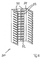
- Fig. 5 shows a receptacle 30 of a distributor block according to the invention according to a further embodiment of the present invention, wherein in the embodiment of the Fig. 5 Compensation devices 32 are arranged on a rear side 31 of receptacle 30 and are integrated into receptacle 30.
- distribution strips can be electrically connected with their Girdles via interfaces 33 which are also formed on the rear wall 31 of the receptacle 30 with the compensation means 32, to ultimately in the communication path between contact elements for the connection incoming cable cores and contact elements for connecting outgoing cable cores to integrate.
- the stages of a multi-stage compensator are offset and integrated in series into an electrical connection path between an incoming cable core contact element and an outgoing cable wire contact element to utilize time shifts and / or stage phase shifts to enhance the compensation effect.
- the compensation devices are preferably designed such that they serve to compensate crosstalk or crosstalk between cable cores of different subscribers.
- the compensation means are preferably designed such that they serve to compensate for crosstalk or cross-talk between cable wires of the same subscriber.
- the compensation devices are integrated either detachably or non-detachably into the respective electrical connection paths between contact elements for the connection of incoming cable cores and contact elements for the connection of outgoing cable cores.
Landscapes
- Engineering & Computer Science (AREA)
- Computer Networks & Wireless Communication (AREA)
- Details Of Connecting Devices For Male And Female Coupling (AREA)
- Coupling Device And Connection With Printed Circuit (AREA)
Description
Die Erfindung betrifft eine Verteilerleiste einer Telekommunikationsanlage gemäß dem Oberbegriff des Anspruchs 1.The invention relates to a distribution strip of a telecommunications system according to the preamble of claim 1.
Die
Weiterhin ist es aus der
Zur Realisierung hoher Packungsdichten werden die Verteilerleisten sowie die Drahtführungselemente mit möglichst geringen Abmessungen sowie möglichst kompakt ausgeführt. Kabeladern liegen demnach dicht beieinander. Insbesondere bei der Übertragung von Daten mit hohen Übertragungsfrequenzen kann es zwischen Kabeladern unterschiedlicher Teilnehmer, die an einem solchen Verteilerblock rangiert bzw. verdrahtet werden, zu einem unerwünschten sogenannten Nebensprechen oder Übersprechen kommen.To realize high packing densities, the distribution strips and the wire guide elements are designed as compact as possible and as compact as possible. Cable cores are therefore close to each other. Especially in the transmission of data with high transmission frequencies, there may be an undesirable so-called crosstalk or crosstalk between cable wires of different participants who are routed or wired to such a distributor block.
Insbesondere dann, wenn xDSL-Dienste wie zum Beispiel VDSL-Dienste mit Übertragungsfrequenzen von mehr als 10 MHz auf den Kabeladern übertragen werden, kann es auch zwischen Kabeladern desselben Teilnehmers zu einem unerwünschten sogenannten Nebensprechen oder Übersprechen kommen. So kann insbesondere das hochfrequente Datensignal von der Kabelader, auf welcher das kombinierte Sprach-Daten-Signal übertragen wird, unter Umgehung einer xDSL-Splittereinrichtung auf die Kabelader überspringen, auf welcher ausschließlich das niederfrequente Sprachsignal zu übertragen ist.In particular, when xDSL services such as VDSL services with transmission frequencies of more than 10 MHz are transmitted on the cable wires, it can also lead to unwanted so-called crosstalk or crosstalk between cable wires of the same subscriber. In particular, the high-frequency data signal from the cable core on which the combined voice-data signal is transmitted, bypassing an xDSL splitter device, can jump over to the cable core on which only the low-frequency voice signal is to be transmitted.
Durch das sogenannte Nebensprechen oder das Übersprechen wird die Übertragungsqualität beeinträchtigt.Due to the so-called crosstalk or crosstalk the transmission quality is impaired.
Um dem Problem des Nebensprechens bzw. Übersprechens Rechnung zu tragen, werden bei aus dem Stand der Technik bekannten Verteilereinrichtungen von Telekommunikationsanlagen, so bei der aus der
Die
Hiervon ausgehend liegt der vorliegenden Erfindung das Problem zu Grunde, eine neuartige Verteilereinrichtung einer Telekommunikationsanlage zu schaffen.On this basis, the present invention is based on the problem to provide a novel distribution device of a telecommunications system.
Nach einem ersten Aspekt der hier vorliegenden Erfindung wird dieses Problem durch eine Verteilerleiste mit den Merkmalen des Anspruchs 1 gelöst.According to a first aspect of the present invention, this problem is solved by a distributor bar having the features of claim 1.
Mit der hier vorliegenden Erfindung wird erstmals vorgeschlagen, in eine Verteilerleiste einer Telekommunikationseinrichtung Kompensationseinrichtung zu integrieren, die der Kompensation von Übersprechen bzw. von Nebensprechen dienen. Hierdurch wird es erstmals möglich, auch bei Verteilerblöcken mit einer hohen Packungsdichte Signale mit hohen Übertragungsfrequenzen störungsfrei zu übertragen.With the present invention, it is proposed for the first time to integrate compensation devices in a distributor strip of a telecommunication device which serve to compensate crosstalk or crosstalk. This makes it possible for the first time, even with distribution blocks with a high packing density to transmit signals with high transmission frequencies trouble-free.
Die Kompensationseinrichtungen sind in den elektrischen Signalweg zwischen Kontaktelementen für den Anschluss ankommender Kabeladern und Kontaktelementen für den Anschluss abgehender Kabeladern integriert, nämlich entweder lösbar oder unlösbar.The compensation devices are integrated in the electrical signal path between contact elements for the connection of incoming cable cores and contact elements for the connection of outgoing cable cores, namely either solvable or insoluble.
Im Sinne der hier vorliegenden Erfindung sind in der Verteilerleiste bzw. im Verteilerblock durch Übersprechen bzw. Nebensprechen verursachte Übertragungsstörungen aus den zu übertragenden Signalen entfernbar. Dies ist ein deutlicher Unterschied zum Stand der Technik, in welchem lediglich durch Schirmungseinrichtungen versucht wird, durch Übersprechen bzw. Nebensprechen verursachte Übertragungsstörungen zu unterbinden.For the purposes of the present invention, transmission disturbances caused by crosstalk or crosstalk in the distributor strip or in the distributor block can be removed from the signals to be transmitted. This is a clear difference from the prior art, in which it is attempted only by shielding devices to prevent crosstalk caused by crosstalk or transmission interference.
Bevorzugte Weiterbildungen der Erfindung ergeben sich aus den Unteransprüchen und der nachfolgenden Beschreibung. Ausführungsbeispiele werden anhand der Zeichnung näher erläutert. In der Zeichnung zeigt:
- Fig. 1
- eine erfindungsgemäße Verteilereinrichtung, nämlich eine Verteilerleiste, nach einem ersten Ausführungsbeispiel der Erfindung in perspektivischer Ansicht;
- Fig. 2
- eine erfindungsgemäße Verteilereinrichtung, nämlich eine Verteilerleiste, nach einem zweiten Ausführungsbeispiel der Erfindung in perspektivischer Ansicht;
- Fig. 3:
- eine erfindungsgemäße Verteilereinrichtung, nämlich einen Verteilerblock, mit mehreren erfindungsgemäßen Verteilerleisten nach einem dritten Ausführungsbeispiel der Erfindung in perspektivischer Ansicht;
- Fig. 4:
- ein Kassettenelement des erfindungsgemäßen Verteilerblocks bzw. der erfindungsgemäßen Verteilerleiste gemäß
Fig. 1 in perspektivischer, gegenüberFig. 1 um in etwa 90° gedrehter Ansicht; und - Fig. 5:
- eine Aufnahmewanne einer erfindungsgemäßen Verteilereinrichtung, nämlich eines Verteilerblock, nach einem vierten Ausführungsbeispiel der Erfindung in perspektivischer Ansicht.
- Fig. 1
- a distribution device according to the invention, namely a distribution strip, according to a first embodiment of the invention in a perspective view;
- Fig. 2
- a distribution device according to the invention, namely a distribution strip, according to a second embodiment of the invention in a perspective view;
- 3:
- a distributor device according to the invention, namely a distributor block, with a plurality of distributor strips according to the invention according to a third embodiment of the invention in a perspective view;
- 4:
- a cassette element of the distributor block according to the invention or the distributor strip according to the invention according to FIG
Fig. 1 in perspective, oppositeFig. 1 around about 90 ° rotated view; and - Fig. 5:
- a receptacle of a distribution device according to the invention, namely a manifold block, according to a fourth embodiment of the invention in a perspective view.
Erste Kontaktelemente 11, die in einer Reihe nebeneinander angeordnet sind, dienen dem Anschluss ankommender Kabeladern an die Verteilerleiste 10. Zweite Kontaktelemente 12, die ebenfalls in einer Reihe nebeneinander und damit oberhalb bzw. unterhalb der Reihe aus den ersten Kontaktelementen 11 angeordnet sind, dienen dem Anschluss abgehender Kabeladern an die Verteilerleiste 10.First contact elements 11, which are arranged side by side in a row, serve to connect incoming cable cores to the
Sowohl mit den ersten Kontaktelementen 11 als auch mit den zweiten Kontaktelementen 12 sind Kontaktfedem elektrisch leitend verbunden, wobei in
In die in
Im gezeigten Ausführungsbeispiel der
Im Ausführungsbeispiel der
Ein weiteres Ausführungsbeispiel einer erfindungsgemäßen Verteilerleiste 15 zeigt
Die Kontaktelemente 16 für den Anschluss ankommender Kabeladern sowie die Kontaktelemente 17 für den Anschluss abgehender Kabeladern sind wiederum in jeweils einer Reihe nebeneinander angeordnet, wobei die Reihe mit den Kontaktelementen 16 für den Anschluss ankommender Kabeladern in
Auch die Verteilerleiste 15 des Ausführungsbeispiels der
Wie
Ein weiteres Ausführungsbeispiel der Erfindung wird nachfolgend unter Bezugnahme auf
In die Verteilerleisten 25 des Verteilerblocks 23 und damit in den Verteilerblock 23 sind Kompensationseinrichtungen 27 integriert, wobei die Kompensationseinrichtungen 27 in den elektrischen Verbindungsweg zwischen den Kontaktelementen für den Anschluss ankommender Kabeladern und den Kontaktelementen für den Anschluss abgehender Kabeladern geschaltet sind. In
Gegenüber der in
Die Ausführungsbeispiele der
Im Unterschied zu dem in
In die Aufnahmewanne 30 einzuführende, nicht-dargestellte Verteilerleisten können mit ihren Kontaktfedem über Schnittstellen 33, die ebenfalls an der Rückwand 31 der Aufnahmewanne 30 ausgebildet sind, mit den Kompensationseinrichtungen 32 elektrisch leitend verbunden werden, um dieselben letztendlich in den Verbindungsweg zwischen Kontaktelementen für den Anschluss ankommender Kabeladern und Kontaktelementen für den Anschluss abgehender Kabeladern zu integrieren.In the
Die in die Verteilereinrichtungen integrierten Kompensationseinrichtungen können als mehrstufige Kompensationseinrichtungen ausgeführt sein, um Nebensprechen bzw. Übersprechen im Sinne einer Grobkompensation und einer nachgeschalteten Feinkompensation zu kompensieren.The compensation devices integrated in the distributor devices can be embodied as multi-stage compensation devices in order to compensate crosstalk in the sense of a coarse compensation and a downstream fine compensation.
Die Stufen einer mehrstufigen Kompensationseinrichtung sind ortsversetzt und in Reihe in einen elektrischen Verbindungsweg zwischen einem Kontaktelement für den Anschluss einer ankommenden Kabelader und einem Kontaktelement für den Anschluss einer abgehenden Kabelader integriert, um so Zeitverschiebungen und/oder Phasenverschiebungen der Stufen zur Verstärkung des Kompensationseffekts zu nutzen.The stages of a multi-stage compensator are offset and integrated in series into an electrical connection path between an incoming cable core contact element and an outgoing cable wire contact element to utilize time shifts and / or stage phase shifts to enhance the compensation effect.
Die Kompensationseinrichtungen sind vorzugsweise derart ausgestaltet, dass dieselben dem Kompensieren von Übersprechen bzw. von Nebensprechen zwischen Kabeladern unterschiedlicher Teilnehmer dienen.The compensation devices are preferably designed such that they serve to compensate crosstalk or crosstalk between cable cores of different subscribers.
Nach einer Weiterbildung der hier vorliegenden Erfindung können zusätzlich zu den Kompensationseinrichtungen auch xDSL-Splittereinrichtungen zusammen mit den Kompensationseinrichtungen in die Verteilereinrichtungen integriert sein. Vorzugsweise sind dann die Kompensationseinrichtungen sowie die xDSL-Splittereinrichtungen gemeinsam in einen elektrischen Verbindungsweg zwischen einem Kontaktelement für den Anschluss ankommender Kabeladern und einem Kontaktelement für den Anschluss abgehender geschaltet. Bei den xDSL-Splittereinrichtungen handelt es sich insbesondere um VDSL-Splittereinrichtungen.According to a development of the present invention, in addition to the compensation devices, xDSL splitter devices can also be integrated into the distributor devices together with the compensation devices. Preferably, then, the compensation devices and the xDSL splitter devices are connected together in an electrical connection path between a contact element for the connection of incoming cable cores and a contact element for the connection outgoing. The xDSL splitter devices are in particular VDSL splitter devices.
In diesem Fall sind die Kompensationseinrichtungen vorzugsweise derart ausgestaltet, dAss dieselben dem Kompensieren von Übersprechen bzw. von Nebensprechen zwischen Kabeladern desselben Teilnehmers dienen.In this case, the compensation means are preferably designed such that they serve to compensate for crosstalk or cross-talk between cable wires of the same subscriber.
In den gezeigten Ausführungsbeispielen sind die Kompensationseinrichtungen entweder lösbar oder unlösbar in die jeweiligen elektrischen Verbindungswege zwischen Kontaktelementen für den Anschluss ankommender Kabeladern und Kontaktelementen für den Anschluss abgehender Kabeladern integriert. Es ist kein Verdrahtungsaufwand bzw. Verkabelungsaufwand zwischen den Kompensationseinrichtungen und den Kontaktfedern der Verteilerleisten erforderlich. Auch dann, wenn die Kompensationseinrichtungen lösbar in das Funktionselement einer Verteilerleiste integriert sind, ist kein Verdrahtungsaufwand erforderlich. Vielmehr können als Kassettenelemente oder Einzelstecker ausgebildete Kompensationseinrichtungen über Kontaktzungen bzw. Kontaktleisten einfach mit den Kontaktfedem elektrisch kontaktiert werden, nämlich durch Einschieben derselben zwischen die Kontaktfedern.In the exemplary embodiments shown, the compensation devices are integrated either detachably or non-detachably into the respective electrical connection paths between contact elements for the connection of incoming cable cores and contact elements for the connection of outgoing cable cores. There is no wiring effort or cabling between the compensation devices and the contact springs of the distribution strips required. Even if the compensation devices are detachably integrated into the functional element of a distribution strip, no wiring effort is required. Rather, designed as cassette elements or single connector compensation devices can be contacted via contact tongues or contact strips simply with the Kontaktfedem electrically, namely by inserting the same between the contact springs.
- 1010
- Verteilerleisterail
- 1111
- Kontaktelementcontact element
- 1212
- Kontaktelementcontact element
- 1313
- Kontaktfedercontact spring
- 1414
- Kompensationseinrichtungcompensator
- 1515
- Verteilerleisterail
- 1616
- Kontaktelementcontact element
- 1717
- Kontaktelementcontact element
- 1818
- Kontaktfedercontact spring
- 1919
- Kompensationseinrichtungcompensator
- 2020
- Platinecircuit board
- 2121
- Kontaktzungecontact tongue
- 2222
- Öffnungopening
- 2323
- Verteilerblockdistribution block
- 2424
- Aufnahmewannereceptacle
- 2525
- Verteilerleisterail
- 2626
- DrahtführungselementWire guide element
- 2727
- Kompensationseinrichtungcompensator
- 2828
- Kassettenelementcassette member
- 2929
- Kontaktleistecontact strip
- 3030
- Aufnahmewannereceptacle
- 3131
- Rückwandrear wall
- 3232
- Kompensationseinrichtungcompensator
Claims (8)
- Distribution strip of a telecommunications system, with a functional element, the functional element having contact elements for the connection of incoming cable cores and contact elements for the connection of outgoing cable cores, and the functional element furthermore having contact springs, which are electrically conductively connected to the contact elements, for producing connections between incoming cable cores and outgoing cable cores, characterized by at least one multi-stage compensation device (14; 19; 27), which is integrated in an electrical connecting path between a contact element for the connection of an incoming cable core and a contact element for the connection of an outgoing cable core, the or each compensation device (14; 19; 27) being used for compensation of crosstalk or side-to-side crosstalk between cable cores of different subscribers via coarse compensation and fine compensation, whereby stages of a multi-stage compensation device being integrated, spatially offset and in series, into an electrical connecting path between a contact element for the connection of an incoming cable core and a contact element for the connection of an outgoing cable core in such a way that temporal shifts and/or phase shifts of the stages can be used for enhancing the compensation effect.
- Distribution strip according to Claim 1, characterized in that the or each compensation device (14) is integrated in the functional element in such a way that the or each compensation device (14) non-detachably into the respective electrical connecting path between a contact element for the connection of an incoming cable core and a contact element for the connection of an outgoing cable core.
- Distribution strip according to Claim 1, characterized in that the or each compensation device (19; 27) is integrated in the functional element in such a way that the or each compensation device (19; 27) is connected detachably into the respective electrical connecting path between a contact element for the connection of an incoming cable core and a contact element for the connection of an outgoing cable core.
- Distribution strip according to Claim 3, characterized in that compensation devices (27) for different subscribers are combined to form a cassette element (28), which has a contact strip (29), via which said cassette element can be introduced at a rear side of the functional element between contact springs of the functional element.
- Distribution strip according to Claim 3, characterized in that compensation devices (19) for different subscribers are combined to form a printed circuit board (20), which has contact tongues (21), via which said printed circuit board can be introduced at a front side of the functional elements between contact springs of the functional element.
- Distribution strip according to Claim 3, characterized in that each compensation device for a subscriber is in the form of an individual plug and can be introduced, via individual contact tongues, at a front side of the functional element between contact springs of the functional element.
- Distribution strip according to one or more of Claims 1 to 6, characterized in that, in addition to compensation devices, xDSL splitter devices are also integrated in the electrical connecting path between contact elements for the connection of incoming cable cores and contact elements for the connection of outgoing cable cores.
- Distribution strip according to Claim 7, characterized in that the or each compensation device is configured in such a way that it is used for compensating for side-to-side crosstalk or crosstalk between cable cores.
Applications Claiming Priority (2)
| Application Number | Priority Date | Filing Date | Title |
|---|---|---|---|
| DE200620005683 DE202006005683U1 (en) | 2006-04-05 | 2006-04-05 | Distribution device of a telecommunications system |
| PCT/EP2007/001521 WO2007115604A1 (en) | 2006-04-05 | 2007-02-22 | Distributor device of a telecommunication system comprising a compensating device |
Publications (2)
| Publication Number | Publication Date |
|---|---|
| EP2002665A1 EP2002665A1 (en) | 2008-12-17 |
| EP2002665B1 true EP2002665B1 (en) | 2012-10-24 |
Family
ID=36776687
Family Applications (1)
| Application Number | Title | Priority Date | Filing Date |
|---|---|---|---|
| EP07722897A Not-in-force EP2002665B1 (en) | 2006-04-05 | 2007-02-22 | Distributor device of a telecommunication system comprising a compensating device |
Country Status (3)
| Country | Link |
|---|---|
| EP (1) | EP2002665B1 (en) |
| DE (1) | DE202006005683U1 (en) |
| WO (1) | WO2007115604A1 (en) |
Family Cites Families (4)
| Publication number | Priority date | Publication date | Assignee | Title |
|---|---|---|---|---|
| DE10029870A1 (en) * | 2000-06-16 | 2002-01-03 | Rxs Kabelgarnituren Gmbh & Co | Distribution device of a data signal processing system and data signal processing system |
| EP1455418A1 (en) * | 2003-03-03 | 2004-09-08 | 3M Innovative Properties Company | Telecommunications module |
| CA2547029C (en) * | 2003-11-21 | 2012-10-23 | Leviton Manufacturing Co., Inc. | Compensation system and method for negative capacitive coupling in idc |
| US7187766B2 (en) * | 2004-02-20 | 2007-03-06 | Adc Incorporated | Methods and systems for compensating for alien crosstalk between connectors |
-
2006
- 2006-04-05 DE DE200620005683 patent/DE202006005683U1/en not_active Expired - Lifetime
-
2007
- 2007-02-22 WO PCT/EP2007/001521 patent/WO2007115604A1/en active Application Filing
- 2007-02-22 EP EP07722897A patent/EP2002665B1/en not_active Not-in-force
Also Published As
| Publication number | Publication date |
|---|---|
| DE202006005683U1 (en) | 2006-07-20 |
| EP2002665A1 (en) | 2008-12-17 |
| WO2007115604A1 (en) | 2007-10-18 |
Similar Documents
| Publication | Publication Date | Title |
|---|---|---|
| EP1290762B1 (en) | Distributor module for use in telecommunications and data systems technology | |
| EP1592097B1 (en) | Connector with cross-talk compensation | |
| EP1527503B1 (en) | Distributor connection module for telecommunication and data technology | |
| DE60203679T2 (en) | Electrical connector with reduced crosstalk | |
| DE20104605U1 (en) | Terminal block and distribution device | |
| EP1422948A2 (en) | Distribution device in a data signal processing installation and data signal processing installation | |
| DE102005022689B4 (en) | Active distribution device in the subscriber access area | |
| WO2006094570A1 (en) | Distribution device pertaining to a telecommunication installation | |
| EP2002665B1 (en) | Distributor device of a telecommunication system comprising a compensating device | |
| DE602004007477T2 (en) | Modular arrangement in the field of telecommunications | |
| DE202008005934U1 (en) | Distribution bar of a telecommunications system | |
| DE19925654C2 (en) | Terminal block for high transmission rates | |
| EP1993297B1 (en) | Distribution block of a telecommunication device | |
| DE102009051314B4 (en) | Distribution device for telecommunications and data technology | |
| EP2201786B1 (en) | Distribution device of a telecommunications system and plug for a distribution device of a telecommunications system | |
| EP1381243A1 (en) | Distributor system of a telecommunication installation | |
| EP2057717B1 (en) | Distribution device of a telecommunications installation, accommodating device for such a distribution device and jumper connector | |
| EP1982533A1 (en) | Shielding device for distributing blocks | |
| WO2007090489A1 (en) | Shielding device for distribution blocks | |
| DE102014226422A1 (en) | Distribution device for telecommunications and data technology and plug or magazine | |
| DE202006016752U1 (en) | Distributing device e.g. distributor cabinet, for use in telecommunication arrangement, has digital subscriber line access multiplier-data signaling lines leading to plug-in connector units and intercepted in intercepting devices | |
| DE102010007856A1 (en) | Method and disconnect bar for alternatively connecting an output line connected to a first input line to a second input line | |
| DE20023395U1 (en) | Distribution device in data signal processing system has data signal processing unit with active/passive electronic components integrated into block components |
Legal Events
| Date | Code | Title | Description |
|---|---|---|---|
| PUAI | Public reference made under article 153(3) epc to a published international application that has entered the european phase |
Free format text: ORIGINAL CODE: 0009012 |
|
| 17P | Request for examination filed |
Effective date: 20080913 |
|
| AK | Designated contracting states |
Kind code of ref document: A1 Designated state(s): AT BE BG CH CY CZ DE DK EE ES FI FR GB GR HU IE IS IT LI LT LU LV MC NL PL PT RO SE SI SK TR |
|
| 17Q | First examination report despatched |
Effective date: 20111011 |
|
| GRAP | Despatch of communication of intention to grant a patent |
Free format text: ORIGINAL CODE: EPIDOSNIGR1 |
|
| DAX | Request for extension of the european patent (deleted) | ||
| GRAS | Grant fee paid |
Free format text: ORIGINAL CODE: EPIDOSNIGR3 |
|
| GRAA | (expected) grant |
Free format text: ORIGINAL CODE: 0009210 |
|
| AK | Designated contracting states |
Kind code of ref document: B1 Designated state(s): AT BE BG CH CY CZ DE DK EE ES FI FR GB GR HU IE IS IT LI LT LU LV MC NL PL PT RO SE SI SK TR |
|
| REG | Reference to a national code |
Ref country code: GB Ref legal event code: FG4D Free format text: NOT ENGLISH |
|
| REG | Reference to a national code |
Ref country code: CH Ref legal event code: EP |
|
| REG | Reference to a national code |
Ref country code: AT Ref legal event code: REF Ref document number: 581447 Country of ref document: AT Kind code of ref document: T Effective date: 20121115 |
|
| REG | Reference to a national code |
Ref country code: IE Ref legal event code: FG4D Free format text: LANGUAGE OF EP DOCUMENT: GERMAN |
|
| REG | Reference to a national code |
Ref country code: DE Ref legal event code: R096 Ref document number: 502007010754 Country of ref document: DE Effective date: 20121220 |
|
| REG | Reference to a national code |
Ref country code: NL Ref legal event code: VDEP Effective date: 20121024 |
|
| PG25 | Lapsed in a contracting state [announced via postgrant information from national office to epo] |
Ref country code: NL Free format text: LAPSE BECAUSE OF FAILURE TO SUBMIT A TRANSLATION OF THE DESCRIPTION OR TO PAY THE FEE WITHIN THE PRESCRIBED TIME-LIMIT Effective date: 20121024 Ref country code: IS Free format text: LAPSE BECAUSE OF FAILURE TO SUBMIT A TRANSLATION OF THE DESCRIPTION OR TO PAY THE FEE WITHIN THE PRESCRIBED TIME-LIMIT Effective date: 20130224 Ref country code: SE Free format text: LAPSE BECAUSE OF FAILURE TO SUBMIT A TRANSLATION OF THE DESCRIPTION OR TO PAY THE FEE WITHIN THE PRESCRIBED TIME-LIMIT Effective date: 20121024 Ref country code: FI Free format text: LAPSE BECAUSE OF FAILURE TO SUBMIT A TRANSLATION OF THE DESCRIPTION OR TO PAY THE FEE WITHIN THE PRESCRIBED TIME-LIMIT Effective date: 20121024 |
|
| PG25 | Lapsed in a contracting state [announced via postgrant information from national office to epo] |
Ref country code: SI Free format text: LAPSE BECAUSE OF FAILURE TO SUBMIT A TRANSLATION OF THE DESCRIPTION OR TO PAY THE FEE WITHIN THE PRESCRIBED TIME-LIMIT Effective date: 20121024 Ref country code: GR Free format text: LAPSE BECAUSE OF FAILURE TO SUBMIT A TRANSLATION OF THE DESCRIPTION OR TO PAY THE FEE WITHIN THE PRESCRIBED TIME-LIMIT Effective date: 20130125 Ref country code: LV Free format text: LAPSE BECAUSE OF FAILURE TO SUBMIT A TRANSLATION OF THE DESCRIPTION OR TO PAY THE FEE WITHIN THE PRESCRIBED TIME-LIMIT Effective date: 20121024 Ref country code: PL Free format text: LAPSE BECAUSE OF FAILURE TO SUBMIT A TRANSLATION OF THE DESCRIPTION OR TO PAY THE FEE WITHIN THE PRESCRIBED TIME-LIMIT Effective date: 20121024 Ref country code: PT Free format text: LAPSE BECAUSE OF FAILURE TO SUBMIT A TRANSLATION OF THE DESCRIPTION OR TO PAY THE FEE WITHIN THE PRESCRIBED TIME-LIMIT Effective date: 20130225 Ref country code: CY Free format text: LAPSE BECAUSE OF FAILURE TO SUBMIT A TRANSLATION OF THE DESCRIPTION OR TO PAY THE FEE WITHIN THE PRESCRIBED TIME-LIMIT Effective date: 20121024 |
|
| PG25 | Lapsed in a contracting state [announced via postgrant information from national office to epo] |
Ref country code: BG Free format text: LAPSE BECAUSE OF FAILURE TO SUBMIT A TRANSLATION OF THE DESCRIPTION OR TO PAY THE FEE WITHIN THE PRESCRIBED TIME-LIMIT Effective date: 20130124 Ref country code: SK Free format text: LAPSE BECAUSE OF FAILURE TO SUBMIT A TRANSLATION OF THE DESCRIPTION OR TO PAY THE FEE WITHIN THE PRESCRIBED TIME-LIMIT Effective date: 20121024 Ref country code: CZ Free format text: LAPSE BECAUSE OF FAILURE TO SUBMIT A TRANSLATION OF THE DESCRIPTION OR TO PAY THE FEE WITHIN THE PRESCRIBED TIME-LIMIT Effective date: 20121024 Ref country code: DK Free format text: LAPSE BECAUSE OF FAILURE TO SUBMIT A TRANSLATION OF THE DESCRIPTION OR TO PAY THE FEE WITHIN THE PRESCRIBED TIME-LIMIT Effective date: 20121024 Ref country code: EE Free format text: LAPSE BECAUSE OF FAILURE TO SUBMIT A TRANSLATION OF THE DESCRIPTION OR TO PAY THE FEE WITHIN THE PRESCRIBED TIME-LIMIT Effective date: 20121024 |
|
| PG25 | Lapsed in a contracting state [announced via postgrant information from national office to epo] |
Ref country code: RO Free format text: LAPSE BECAUSE OF FAILURE TO SUBMIT A TRANSLATION OF THE DESCRIPTION OR TO PAY THE FEE WITHIN THE PRESCRIBED TIME-LIMIT Effective date: 20121024 Ref country code: IT Free format text: LAPSE BECAUSE OF FAILURE TO SUBMIT A TRANSLATION OF THE DESCRIPTION OR TO PAY THE FEE WITHIN THE PRESCRIBED TIME-LIMIT Effective date: 20121024 |
|
| PLBE | No opposition filed within time limit |
Free format text: ORIGINAL CODE: 0009261 |
|
| STAA | Information on the status of an ep patent application or granted ep patent |
Free format text: STATUS: NO OPPOSITION FILED WITHIN TIME LIMIT |
|
| BERE | Be: lapsed |
Owner name: CCS TECHNOLOGY, INC. Effective date: 20130228 |
|
| PG25 | Lapsed in a contracting state [announced via postgrant information from national office to epo] |
Ref country code: MC Free format text: LAPSE BECAUSE OF NON-PAYMENT OF DUE FEES Effective date: 20130228 |
|
| REG | Reference to a national code |
Ref country code: CH Ref legal event code: PL |
|
| 26N | No opposition filed |
Effective date: 20130725 |
|
| GBPC | Gb: european patent ceased through non-payment of renewal fee |
Effective date: 20130222 |
|
| PG25 | Lapsed in a contracting state [announced via postgrant information from national office to epo] |
Ref country code: ES Free format text: LAPSE BECAUSE OF FAILURE TO SUBMIT A TRANSLATION OF THE DESCRIPTION OR TO PAY THE FEE WITHIN THE PRESCRIBED TIME-LIMIT Effective date: 20130204 Ref country code: CH Free format text: LAPSE BECAUSE OF NON-PAYMENT OF DUE FEES Effective date: 20130228 Ref country code: LI Free format text: LAPSE BECAUSE OF NON-PAYMENT OF DUE FEES Effective date: 20130228 |
|
| REG | Reference to a national code |
Ref country code: DE Ref legal event code: R097 Ref document number: 502007010754 Country of ref document: DE Effective date: 20130725 |
|
| REG | Reference to a national code |
Ref country code: IE Ref legal event code: MM4A |
|
| PG25 | Lapsed in a contracting state [announced via postgrant information from national office to epo] |
Ref country code: BE Free format text: LAPSE BECAUSE OF NON-PAYMENT OF DUE FEES Effective date: 20130228 Ref country code: GB Free format text: LAPSE BECAUSE OF NON-PAYMENT OF DUE FEES Effective date: 20130222 Ref country code: IE Free format text: LAPSE BECAUSE OF NON-PAYMENT OF DUE FEES Effective date: 20130222 |
|
| REG | Reference to a national code |
Ref country code: AT Ref legal event code: MM01 Ref document number: 581447 Country of ref document: AT Kind code of ref document: T Effective date: 20130222 |
|
| PG25 | Lapsed in a contracting state [announced via postgrant information from national office to epo] |
Ref country code: AT Free format text: LAPSE BECAUSE OF NON-PAYMENT OF DUE FEES Effective date: 20130222 |
|
| PGFP | Annual fee paid to national office [announced via postgrant information from national office to epo] |
Ref country code: FR Payment date: 20140220 Year of fee payment: 8 |
|
| PG25 | Lapsed in a contracting state [announced via postgrant information from national office to epo] |
Ref country code: LT Free format text: LAPSE BECAUSE OF FAILURE TO SUBMIT A TRANSLATION OF THE DESCRIPTION OR TO PAY THE FEE WITHIN THE PRESCRIBED TIME-LIMIT Effective date: 20121024 |
|
| PG25 | Lapsed in a contracting state [announced via postgrant information from national office to epo] |
Ref country code: TR Free format text: LAPSE BECAUSE OF FAILURE TO SUBMIT A TRANSLATION OF THE DESCRIPTION OR TO PAY THE FEE WITHIN THE PRESCRIBED TIME-LIMIT Effective date: 20121024 |
|
| PG25 | Lapsed in a contracting state [announced via postgrant information from national office to epo] |
Ref country code: HU Free format text: LAPSE BECAUSE OF FAILURE TO SUBMIT A TRANSLATION OF THE DESCRIPTION OR TO PAY THE FEE WITHIN THE PRESCRIBED TIME-LIMIT; INVALID AB INITIO Effective date: 20070222 Ref country code: LU Free format text: LAPSE BECAUSE OF NON-PAYMENT OF DUE FEES Effective date: 20130222 |
|
| REG | Reference to a national code |
Ref country code: FR Ref legal event code: ST Effective date: 20151030 |
|
| PG25 | Lapsed in a contracting state [announced via postgrant information from national office to epo] |
Ref country code: FR Free format text: LAPSE BECAUSE OF NON-PAYMENT OF DUE FEES Effective date: 20150302 |
|
| PGFP | Annual fee paid to national office [announced via postgrant information from national office to epo] |
Ref country code: DE Payment date: 20190115 Year of fee payment: 13 |
|
| REG | Reference to a national code |
Ref country code: DE Ref legal event code: R119 Ref document number: 502007010754 Country of ref document: DE |
|
| PG25 | Lapsed in a contracting state [announced via postgrant information from national office to epo] |
Ref country code: DE Free format text: LAPSE BECAUSE OF NON-PAYMENT OF DUE FEES Effective date: 20200901 |