EP2002254B1 - Method of producing a measurement sensor for high-temperature applications - Google Patents
Method of producing a measurement sensor for high-temperature applications Download PDFInfo
- Publication number
- EP2002254B1 EP2002254B1 EP07727143.5A EP07727143A EP2002254B1 EP 2002254 B1 EP2002254 B1 EP 2002254B1 EP 07727143 A EP07727143 A EP 07727143A EP 2002254 B1 EP2002254 B1 EP 2002254B1
- Authority
- EP
- European Patent Office
- Prior art keywords
- tube
- sensor
- glass
- sleeve
- sensor element
- Prior art date
- Legal status (The legal status is an assumption and is not a legal conclusion. Google has not performed a legal analysis and makes no representation as to the accuracy of the status listed.)
- Not-in-force
Links
Images


Classifications
-
- G—PHYSICS
- G01—MEASURING; TESTING
- G01K—MEASURING TEMPERATURE; MEASURING QUANTITY OF HEAT; THERMALLY-SENSITIVE ELEMENTS NOT OTHERWISE PROVIDED FOR
- G01K1/00—Details of thermometers not specially adapted for particular types of thermometer
- G01K1/08—Protective devices, e.g. casings
- G01K1/12—Protective devices, e.g. casings for preventing damage due to heat overloading
Definitions
- the present invention relates to a method of manufacturing a probe.
- the sensor is suitable for the determination of physical quantities or compositions in rooms or measuring volumes with high temperatures, in particular in the range of about 1000 ° Celsius.
- sensors whose function is not limited in the long term by the high temperatures.
- An example of this is an exhaust gas sensor in the exhaust system of an internal combustion engine of a motor vehicle.
- Such a sensor is exposed to high stresses in terms of temperature, pressure, vibration and corrosion, so it can lead to premature leaks, measurement inaccuracies or failures.
- a sealing arrangement for a temperature or gas sensor is known in which the sealing element is formed from a graphite foil body.
- a graphite foil body is easy and inexpensive to provide.
- a disadvantage of this solution is that it requires a reducing atmosphere for the application of the sensor at temperatures above 500 ° Celsius and an electrical insulation between the graphite foil body and the sensor. The thermal and mechanical strength of the graphite foil body is not sufficient for many applications.
- the seal has a Glaseinschmelzung.
- this glass fusion allows a potential-free installation of the sensor in the metallic housing of the exhaust system and, on the other hand, the use of glass as a sealing material ensures a high temperature and pressure resistance of this seal.
- the use of glass as a material for the seal requires a special construction of the sealing unit, in particular to ensure the required mechanical stability.
- the sealing unit is essentially formed from a ceramic sealing ring, which is almost completely enclosed by a layer of Glaseinschmelzung. The ceramic sealing ring absorbs a majority of the forces acting on the sealing unit.
- the ceramic sealing ring is designed conical on the one hand, so that he has a can absorb shoulder-shaped sealing seat of the sensor element.
- a pressure-distributing sealing ring is arranged, which distributes the pressure acting on the sensor evenly on the housing seat.
- the sealing unit furthermore has a metallic sleeve in order to ensure the mechanical stability of the sealing unit.
- the disadvantage of this solution is the complex arrangement of several components for the sealing unit, which is necessary through the use of a Glaseinschmelzung. The arrangement of several components to achieve a mechanically stressable attachment of the sensor simultaneously causes a higher susceptibility of the sealing unit, since the interaction of the components can be disturbed under high mechanical stress.
- a housing for a sensor with a cylindrical protective cap is previously known, wherein the protective cap has passage openings.
- the passage openings are circular, wherein the flow path between the exterior of the protective cap and the interior of the protective cap is limited only by the passage openings and connecting lines of the centers of adjacent Umtangsplatz passages on the developed lateral surface of the cap at an angle of 45 ° to the longitudinal axis of the cap ,
- the DE 101 15 704 C1 shows a housing for a temperature or gas sensor.
- the ceramic molding provided there has a slot with a rectangular cross-section.
- a sensor element is added and there are incisions in the ceramic molding, which expose the slot for contacting.
- a fiber bundle is arranged between the sensor element and the protective housing, which prevents vibrations from the sensor.
- the DE 3237824 A1 discloses an automotive exhaust gas oxygen sensor with a ceramic sleeve having an internal bore.
- a titanium oxide pellet is used, the connecting lines are insulated from each other by axial spacers. Each two spacers are sealed by a respective fused glass seal between the spacers and connected to the ceramic sleeve.
- a gas sensor In the US 5,228,975 a gas sensor is shown, the sensor element is installed gas-tight in a ceramic tube.
- the ceramic sleeve is in turn built into a metal housing by a circular spacer and inorganic cement.
- the object of the present invention is to provide a method for producing a glass filling of a sensor for the determination of a physical size or a composition of matter in rooms with high temperature load, for example in the range of ⁇ 1000 ° Celsius, wherein the sensor thus produced in terms of high stresses Temperature, pressure, vibration and corrosion over a long period of a dense and ensures a secure fit.
- the object is achieved by a method for producing a measuring sensor according to claim 1.
- a particular advantage of the invention is that by the design of the fastening sleeve, the introduction of a glass filling is made possible, which simultaneously provides a permanently secure and tight attachment option and electrical insulation against the housing.
- Another advantage of this invention is the resistance of the glass filling against aggressive media, which arise, for example, in the combustion of fuels in the exhaust stream.
- the glass filling is realized by the introduction of a ring produced by pressing, which melts in the melting process.
- the glass material is distributed in a gap provided between the mounting sleeve and the tube. This gap for the injection is in the range up to 8/10 mm width.
- the connecting means glass can be understood in the present case as a pressure-transmitting sealant.
- the Fig. 1 shows a sensor prepared by a method according to the invention as exhaust gas temperature sensor 01.
- the exhaust gas temperature sensor 01 is used to determine the temperature in the exhaust stream in an exhaust system of a motor vehicle with an internal combustion engine.
- the exhaust gas temperature sensor 01 comprises a sensor element 02, which protrudes into the exhaust gas to be measured.
- the sensor element 02 can be formed for example by a temperature sensor of the type PT-200 in the form of a so-called pill.
- a sensor protective sleeve or a simple collecting basket 03 protects the sensor element 02, in particular against larger particles in the exhaust gas flow, which could damage the sensor element 02. However, the sensor protective sleeve 03 also serves to protect the downstream components in the exhaust gas flow in the event that the pill should break off.
- the sensor element 02 is attached to a pipe or rod 04, which serves simultaneously for receiving or for conducting lines for electrical connection of the sensor element 02.
- the exhaust gas temperature sensor 01 has a cable 07 with a plug 08.
- the tube 04 and the sensor element 02 carried by this are fastened with a fastening sleeve 09, for example, on the housing of the exhaust system (not shown).
- the mounting sleeve 09 also serves to seal between the tube 04 and the housing of the exhaust system.
- the mounting sleeve 09 is inserted into a designated opening in the housing of the exhaust system and sheared, for example, with a hollow nut.
- the housing of the exhaust system has at the opening a thread on which the hollow nut 11 is screwed.
- the Fig. 1 shows the exhaust gas temperature sensor in the disassembled state, wherein the hollow nut 11 is slidably disposed on the cable 07 at any position.
- the tube 04 is fixed pressure-tight in the mounting sleeve 09 with a Glaseinschmelzung 12. Since the glass used has a melting temperature of at least 1000 to 1200 ° Celsius, this attachment is grown at the still occurring in the field of mounting sleeve temperatures of eg up to 700 ° Celsius thermal loads. Even after a longer period of operation, the glass melt 12 does not become brittle, so that the attachment retains its strength. Should it come through a damage in the exhaust system to an elevated temperature at the exhaust gas temperature sensor 01, the temperature may briefly more than 700 ° Celsius, without damaging the attachment. Since the glass of the glass seal 12 used has a low thermal conductivity, little heat is transferred from the pipe 04 to the mounting sleeve 09.
- the Glaseinschmelzung 12 represents the only attachment of the tube 04 on the housing of the exhaust system. Since the glass used acts electrically insulating, an electrical insulation of the connecting leads of the sensor element 02 against the ground potential is ensured at the same time on the housing of the exhaust system.
- the tube 04 is at the in Fig. 1 embodiment shown executed cylindrical.
- the fastening sleeve 09 has a cylindrical opening whose diameter is slightly larger than the diameter of the tube 04. Consequently, a circumferential gap 13 remains between the tube 04 and the fastening sleeve 09 before the final sealing.
- the height of the cylindrical opening of the fastening sleeve 09 is preferably a multiple of the diameter of the opening. As a result, the gap 13 extends over a length which is greater than the diameter of the opening. Since the gap 13, which is up to 8/10 mm wide, provides the space for the glass fusion 12, the glass fusion 12 can also have a height which corresponds to a multiple of the diameter of the glass fusion 12.
- the attachment formed by the glass seal 12 has a peripheral surface which is substantially larger than the cross-sectional area of the pipe 04.
- the thickness of the hollow cylindrical Glaseinschmelzung 12 which is determined by the width of the gap 13, substantially smaller than the radius of the opening of the mounting sleeve 09.
- This design of the attachment of the tube 04 to the mounting sleeve 09 allows that formed by the Glaseinschmelzung 12 Mounting high mechanical stresses can withstand. Therefore, it requires no further ceramic or pressure-distributing sealing rings or other fasteners.
- the fastening forces are distributed over the large surface of the hollow cylindrical glass seal 12, so that a claimable attachment is ensured solely by the Glaseinschmelzung 12th
- the glass melting 12 can in particular also permanently absorb the vibration forces occurring at the exhaust system motor vehicle.
- the attachment of the tube 04 in the mounting sleeve 09 is by the use of glass in the Glaseinschmelzung 12 resistant to the aggressive media that arise during the combustion of fuels.
- the Glaseinschmelzung 12 is also corrosion resistant to incoming water. This allows the sensor to be used in other processes where aggressive media and high temperatures occur.
- the circular shape of the sensor protection sleeve 03 allows any angular position in the axis of the sensor protection sleeve when inserting the sensor into the housing of the exhaust system. It must therefore be adhered to when installing the exhaust gas temperature sensor 01 no predetermined angular position.
- a hollow-cylindrical sintered glass body is used. First, this glass is pressed with a binder to a hollow cylindrical sintered glass body. The binder is subsequently removed by evaporation. Small bubbles forming buffer zones remain in the sintered glass body. Subsequently, a sintering process is performed under pressure and at temperatures of about 750 ° C to give the sintered glass body sufficient strength.
- the pressed sintered glass body substantially corresponds in its dimensions to the gap 13 between the tube 04 and the fastening sleeve 09.
- the glass body is dimensioned such that it can be inserted tautly into the gap 13 without the risk of damaging the tube 04.
- the cylindrical design of the tube 04 and the opening of the mounting sleeve 09 allow the telescoping of the tube 04 and the glass body in the mounting sleeve 09 any rotation of the tube 04 in the axis and a large area in which the tube 04 for positioning within the glass body in the mounting sleeve 09 can be moved. Therefore, even with the use of the same mounting sleeves 09, the same glass body and the same tubes 04 fasteners for sensors can be produced, which have a different length of the projecting into the exhaust gas pipe 04.
- a melting of the glass body takes place at temperatures of about 1000 ° Celsius.
- the Glaseinschmelzung 12 which mechanically connects the tube 04 with the mounting sleeve 09 and gas-tight.
- the tube 04 can not be removed from the mounting sleeve 09.
- the produced molten glass 12 has a density of about 3.1 g-cm -3 on.
- the linear thermal expansion coefficient of the glass is about 0.54 ⁇ 10 -6 per Kelvin. Due to the very low linear coefficient of thermal expansion of the glass used ensures that the size of the Glaseinschmelzung 12 almost does not change in the large temperature differences and so damage to the Glaseinschmelzung 12 or the tube 04 is avoided.
- the tube 04 is preferably made of aluminum oxide and has e.g. two continuous axial capillary, through which the connecting lines are guided. Since aluminum oxide has an electrically insulating effect, the two connection lines are electrically insulated from one another by the guide in separate capillaries of the tube 04. At the end of the pipe, which is in the installed state outside the exhaust system, the connection lines 06 exit from the pipe 04 and are connected there to two connecting lines 14 of the cable 07 by electrical connections 16. These connections 16 are formed by solder joints, by Crimptheticen or by welded joints, in particular by ultrasonic welding. In the region of the connections 16, the connection lines 06 of the sensor element 02 and the connection lines 14 of the cable 07 are electrically insulated from each other by a ceramic plate 17. As an alternative to the ceramic plate 17, a Teflon disk for insulating the connecting lines and the connecting lines 14 between the connecting lines 06 and between the connecting lines 14 may be introduced.
- the electrical insulation of the connecting lines 06 and the connecting lines 14 may alternatively be done by overmolding the connecting lines 06 and the connecting lines 14 with a Höchtemperatureckstoff or by casting the connecting lines 06 and the connecting lines 14 in casting resin or high temperature adhesive.
- the electrical connections 16 are protected by a metallic connection protection sleeve 18.
- the connection protection sleeve 18 is fastened to the fastening sleeve 09 with a welded connection.
- the connection protection sleeve 18 is reduced by a curl 19 in its cross section.
- the cable 07 is thereby fastened with a crimped connection in the connection protection sleeve 18.
- a cable protection tube 21 made of polytetrafluoroethylene is pushed onto the cable 07 prior to the production of the crimp connection.
- the mounting sleeve 09 is preferably made of a ferritic stainless steel.
- the sensor protection sleeve 03 is preferably made of a nickel-chromium alloy, in particular Inconel 600 No. 2.4816 made and fastened with a welded connection to the mounting sleeve 09.
- the sensor protection sleeve 03 is provided in the vicinity of the sensor element 02 with a plurality of holes 22 and closed at its free end. Through the holes draws a portion of the exhaust stream, so that permanently exhaust gas flows to the sensor element 02.
- the sensor protection sleeve 03 may be formed by a seamless stainless steel tube, wherein the opening at the free end is reduced by tumbling to 2.0 to 2.5 millimeters. In the free end of the stainless steel tube, for example, eight slots can be introduced. Instead of a seamless tube, a welded tube can also be used.
- the sensor protective sleeve 03 may alternatively be formed by a rolled tube, wherein the tube is provided with by clinching (pressure joining) provided connection points and the opening is closed at the free end with a protective cap.
- the protective cap can also be provided with an opening of 2.0 to 2.5 millimeters. In principle, however, the opening at the free end of the sensor protection sleeve 03 can be completely closed.
- the sensor protection sleeve 03 may also be formed in two pieces such that the first piece of the sensor sleeve 03 is made together with the mounting sleeve 09 by deep drawing a board and the second piece of the sensor sleeve 03 is made in a second deep drawing, the two pieces of the sensor sleeve 03 then be welded.
- the effects of mechanical vibrations in the exhaust system on the exhaust gas temperature sensor 01 can be reduced by one or more stabilizing rings (not shown) in the sensor protection sleeve 03, which are preferably arranged in the vicinity of the sensor element 02.
- the stabilization ring may be firmly inserted into the sensor protection sleeve 03 and have an opening for the passage of the tube 04, wherein this opening is slightly larger than the tube 04, so that the tube 04 can be inserted without much force in the stabilizing ring.
- the stabilizing ring may be fixedly mounted on the tube 04 and have an outer diameter which is slightly smaller than the inner diameter of the sensor protective sleeve 03. Both embodiments of these stabilizing rings can also be combined.
- the stabilizing rings are preferably made of a ceramic material or a carbon material that is suitable for the operating temperature.
- the exhaust gas temperature sensor 01 has no sensor protective sleeve 03.
- This embodiment is to be preferred if particles that could damage the sensor element 02 or the pipe 04 can be excluded in the exhaust gas flow to be measured.
- An advantage of this embodiment in addition to the entry of the sensor protective sleeve 03 and the stabilizing rings, that the exhaust gas flow to be measured can flow unhindered on the sensor element 02 and thus an accurate measurement is possible.
- the sensor may be designed as an exhaust gas temperature sensor 01 or as a sensor for another physical quantity, such as air pressure.
- Another embodiment of the probe is used to determine the composition of the substance, in particular the determination of a gas such as carbon monoxide or ammonia.
- the measuring sensor can also be designed with a plurality of sensor elements 02.
- a first sensor element for determining the exhaust gas temperature and a second sensor element for determining the content of carbon monoxide in the exhaust gas can be arranged together on the pipe 04.
- the tube 04 has four through openings for the passage of four connection lines 06 of the sensor elements 02.
- the arrangement of a plurality of sensor elements 02 in the probe 01 is easily possible, since the attachment of the tube 04 to the mounting sleeve 09 provides both in terms of mechanical strength and in terms of electrical insulation of the leads 06 the necessary conditions. Therefore, more than two sensor elements can be integrated in the sensor, so that a plurality of conventional sensors can be replaced by a single multifunctional probe. As a result, the cost of installation, cable feeders, fasteners, etc. is significantly reduced.
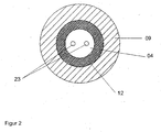
- Fig. 2 shows a sectional view of the mounting sleeve 09 and the tube 04 with the Glaseinschmelzung 12.
- the gap 13 between the mounting sleeve 09 and the tube 04 is made larger in this embodiment, so that the Glaseinschmelzung 12 has a greater thickness.
- the two capillaries 23 for carrying out the connection lines 06 are shown in this illustration.
- Fig. 3 shows a sectional view of the mounting sleeve 09 with the Glaseinschmelzung 12 in a modified embodiment of the sensor with multiple sensor elements 02.
- the sensor has four sensor elements, the sensor for each sensor element 02 has a separate tube 04. Consequently, four tubes 04 passed through the mounting sleeve 09. Each tube 04 has two capillaries 23 for carrying out the connection lines 06 of the respective sensor element 02.
- Fig. 4 shows three sectional views of the mounting sleeve 09 and the tube 04 with the Glaseinschmelzung 12 of four different embodiments of the probe.
- Figure a) the Fig. 4 shows an embodiment in which the tube 04 has an oval cross-sectional area.
- An advantage of this embodiment is the reduced flow resistance of the pipe 04 in the exhaust stream when the pipe 04 is aligned with the narrow side in the direction of the exhaust gas flow. This also requires that the sensor protective sleeve 03 is oval shaped, insofar as it is used. It is within the skill and skill of the art to select the shape of the tube 04 according to the requirements of the particular probe. There are also pipes with a triangular or square cross-section or else special guide grooves in cross-section possible.
- the Fig. 4 shows an embodiment in which the sensor comprises two sensor elements 02, wherein the connecting lines 06 of both sensor elements 02 are guided by a common tube 04. Therefore, the tube 04 has four capillaries 23.
- the tube 04 is like the one in Figure a) the Fig. 4 shown embodiment oval shaped.
- the Fig. 4 shows an embodiment in which the sensor comprises three sensor elements 02, wherein the connecting lines 06 of all three sensor elements 02 are guided through a common tube 04. Therefore, the tube 04 has six capillaries 23.
- the tube 04 may be executed in further embodiments with a larger number of capillaries 23.
- a number of more than two capillaries 23 in the tube 04 is also advantageous if the sensor element 02 requires more than two connecting lines 06.
Description
Die vorliegende Erfindung betrifft ein Verfahren zur Herstellung eines Messfühlers. Der Messfühler eignet sich zur Bestimmung von physikalischen Größen oder Stoffzusammensetzungen in Räumen bzw. Messvolumen mit hohen Temperaturen, insbesondere im Bereich von etwa 1000° Celsius.The present invention relates to a method of manufacturing a probe. The sensor is suitable for the determination of physical quantities or compositions in rooms or measuring volumes with high temperatures, in particular in the range of about 1000 ° Celsius.
Die Kontrolle, Steuerung und Regelung von Prozessen, in denen hohe Temperaturen auftreten, erfordert Messfühler, deren Funktion auch auf Dauer nicht durch die hohen Temperaturen eingeschränkt ist. Ein Beispiel hierfür ist ein Abgassensor in der Abgasanlage eines Verbrennungsmotors eines Kraftfahrzeugs. Ein solcher Sensor ist großen Beanspruchungen hinsichtlich Temperatur, Druck, Erschütterungen und Korrosion ausgesetzt, so dass es frühzeitig zu Undichtigkeiten, Messungenauigkeiten oder Ausfällen kommen kann.The control, control and regulation of processes in which high temperatures occur, requires sensors whose function is not limited in the long term by the high temperatures. An example of this is an exhaust gas sensor in the exhaust system of an internal combustion engine of a motor vehicle. Such a sensor is exposed to high stresses in terms of temperature, pressure, vibration and corrosion, so it can lead to premature leaks, measurement inaccuracies or failures.
Aus der
Aus der
Aus der
Die
Bei dem Verfahren zur Herstellung eines Temperatur- oder Gassensors nach
Zum weiteren Stand der Technik sei noch auf die
Die
In der
Die Aufgabe der vorliegenden Erfindung besteht darin, ein Verfahren zur Herstellung einer Glasfüllung eines Messfühlers für die Bestimmung einer physikalischen Größe oder einer Stoffzusammensetzung in Räumen mit hoher Temperaturbelastung, z.B. im Bereich von ≥ 1000° Celsius bereitzustellen, wobei der so hergestellte Messfühler bei großen Beanspruchungen hinsichtlich Temperatur, Druck, Erschütterungen und Korrosion über einen langen Zeitraum einen dichten und festen Sitz gewährleistet.The object of the present invention is to provide a method for producing a glass filling of a sensor for the determination of a physical size or a composition of matter in rooms with high temperature load, for example in the range of ≥ 1000 ° Celsius, wherein the sensor thus produced in terms of high stresses Temperature, pressure, vibration and corrosion over a long period of a dense and ensures a secure fit.
Die Aufgabe wird gelöst durch ein Verfahren zur Herstellung eines Messfühlers nach Anspruch 1.The object is achieved by a method for producing a measuring sensor according to claim 1.
Ein wichtiger Aspekt der Erfindung ist darin zu sehen, dass eine Glaseinschmelzung als Dichtung zwischen einer äußeren, z.B. metallischen Befestigungshülse und einem durchgeführten, den Sensor tragenden Anschlussrohr fungiert. Weitere Befestigungsmittel oder andere unterstützende Mittel können entfallen.An important aspect of the invention is to be seen in that a glass fusion as a seal between an outer, e.g. metallic mounting sleeve and a performed, carrying the sensor connecting pipe acts. Other fasteners or other supporting means may be omitted.
Ein besonderer Vorteil der Erfindung besteht darin, dass durch die Gestaltung der Befestigungshülse die Einbringung einer Glasfüllung ermöglicht ist, die gleichzeitig eine dauerhaft sichere und dichte Befestigungsmöglichkeit sowie eine elektrische Isolierung gegen das Gehäuse bereitstellt.A particular advantage of the invention is that by the design of the fastening sleeve, the introduction of a glass filling is made possible, which simultaneously provides a permanently secure and tight attachment option and electrical insulation against the housing.
Ein weiterer Vorteil dieser Erfindung ist die Beständigkeit der Glasfüllung gegen aggressive Medien, die beispielsweise bei der Verbrennung von Kraftstoffen im Abgasstrom entstehen.Another advantage of this invention is the resistance of the glass filling against aggressive media, which arise, for example, in the combustion of fuels in the exhaust stream.
Die Glasfüllung wird über das Einbringen eines durch Pressen erzeugten Ringes realisiert, der im Einschmelzprozess aufschmilzt. Beim Aufschmelzen verteilt sich das Glasmaterial in einem vorgesehenen Spalt zwischen der Befestigungshülse und dem Rohr. Dieser Spalt für die Einblasung liegt im Bereich bis zur 8/10 mm Breite. Das Verbindungsmittel Glas kann im vorliegenden Fall als druckübertragendes Dichtmittel verstanden werden.The glass filling is realized by the introduction of a ring produced by pressing, which melts in the melting process. When melting, the glass material is distributed in a gap provided between the mounting sleeve and the tube. This gap for the injection is in the range up to 8/10 mm width. The connecting means glass can be understood in the present case as a pressure-transmitting sealant.
Weitere Vorteile, Einzelheiten und Weiterbildungen der Erfindung ergeben sich aus den nachfolgenden Beschreibungen bevorzugter Ausführungsformen, unter Bezugnahme auf die Zeichnungen. Es zeigen:
-
Fig. 1 einen nach einem erfindungsgemäßen Verfahren hergestellten Messfühler in einer Ausführung als Abgastemperatursensor für ein Kraftfahrzeug; -
Fig. 2 eine Schnittdarstellung einer Dichtungsanordnung des inFig. 1 gezeigten Messfühlers; -
Fig. 3 eine Schnittdarstellung der Dichtungsanordnung einer abgewandelten Ausführungsform des Messfühlers und -
Fig. 4 drei Schnittdarstellung von Dichtungsanordnungen verschiedener Ausführungsformen des Messfühlers.
-
Fig. 1 a sensor manufactured by a method according to the invention in an embodiment as exhaust gas temperature sensor for a motor vehicle; -
Fig. 2 a sectional view of a seal assembly of inFig. 1 shown sensor; -
Fig. 3 a sectional view of the seal assembly of a modified embodiment of the probe and -
Fig. 4 three sectional view of seal assemblies of various embodiments of the probe.
Die
Das Rohr 04 und das von diesem getragene Sensorelement 02 werden mit einer Befestigungshülse 09 z.B. am Gehäuse der Abgasanlage (nicht gezeigt) befestigt. Die Befestigungshülse 09 dient zudem der Abdichtung zwischen dem Rohr 04 und dem Gehäuse der Abgasanlage. Dazu wird die Befestigungshülse 09 in eine dafür vorgesehen Öffnung im Gehäuse der Abgasanlage eingebracht und beispielsweise mit einer Hohlmutter geschert. Das Gehäuse der Abgasanlage weist an der Öffnung ein Gewinde auf, auf welches die Hohlmutter 11 aufgeschraubt wird. Die
Das Rohr 04 ist in der Befestigungshülse 09 mit einer Glaseinschmelzung 12 druckdicht fixiert. Da das verwendete Glas eine Schmelztemperatur von mindestens 1000 bis 1200° Celsius aufweist, ist diese Befestigung bei den in Bereich der Befestigungshülse noch auftretenden Temperaturen von z.B. bis zu 700° Celsius den thermischen Belastungen gewachsen. Auch nach einer längeren Betriebsdauer wird die Glaseinschmelzung 12 nicht spröde, so dass die Befestigung ihre Festigkeit beibehält. Sollte es durch einen Schaden in der Abgasanlage zu eine erhöhten Temperatur am Abgastemperatursensor 01 kommen, so kann die Temperatur kurzzeitig auch mehr als 700° Celsius betragen, ohne dass die Befestigung geschädigt wird. Da das verwendete Glas der Glaseinschmelzung 12 eine geringe Wärmeleitfähigkeit aufweist, wird wenig Wärme vom Rohr 04 auf die Befestigungshülse 09 übertragen. Dadurch ist die thermische Belastung der Befestigungshülse 09 und der Seite des Messfühlers im Bereich der elektrischen Verbindung 16 gemindert. Die Glaseinschmelzung 12 stellt die einzige Befestigung des Rohres 04 am Gehäuse der Abgasanlage dar. Da das verwendete Glas elektrisch isolierend wirkt, ist gleichzeitig eine elektrische Isolation der Anschlussleitungen des Sensorelements 02 gegenüber dem Massepotenzial am Gehäuse der Abgasanlage gewährleistet.The
Das Rohr 04 ist bei der in
Die Befestigung des Rohres 04 in der Befestigungshülse 09 ist durch die Verwendung von Glas in der Glaseinschmelzung 12 beständig gegenüber den aggressiven Medien, die bei der Verbrennung von Kraftstoffen entstehen. Die Glaseinschmelzung 12 ist zudem korrosionsbeständig gegenüber eintretendem Wasser. Dies gestattet den Einsatz des Messfühlers auch in anderen Prozessen, wo aggressive Medien und hohe Temperaturen auftreten.The attachment of the
Die kreisrunde Form der Sensorschutzhülse 03 erlaubt eine beliebige Winkelstellung in der Achse der Sensorschutzhülse beim Einsetzen des Messfühlers in das Gehäuse der Abgasanlage. Es muss daher beim Einbau des Abgastemperatursensors 01 keine vorgegebene Winkelstellung eingehalten werden.The circular shape of the
Zur Herstellung der Glaseinschmelzung 12 zur Befestigung des Rohres 04 in der Befestigungshülse 09 wird ein hohlzylinderförmiger Sinterglaskörper eingesetzt. Zunächst wird hierfür Glas mit einem Bindemittel zu einem hohlzylinderförmigen Sinterglaskörper gepresst. Das Bindemittel wird nachfolgend durch Abdampfen entfernt. In dem Sinterglaskörper verbleiben dabei kleine, Pufferzonen bildende Blasen. Anschließend wird unter Druck und bei Temperaturen von etwa 750°C ein Sintervorgang durchgeführt, um dem Sinterglaskörper eine ausreichende Festigkeit zu geben.To produce the
Der gepresste Sinterglaskörper entspricht in seinen Abmessungen im Wesentlichen dem Spalt 13 zwischen dem Rohr 04 und der Befestigungshülse 09. Der Glaskörper ist so dimensioniert, dass er straff aber ohne die Gefahr einer Beschädigung des Rohrs 04 in den Spalt 13 eingebracht werden kann. Die zylinderförmige Gestaltung des Rohres 04 und der Öffnung der Befestigungshülse 09 erlauben beim Ineinanderschieben des Rohres 04 und des Glaskörpers in der Befestigungshülse 09 eine beliebige Drehung des Rohres 04 in dessen Achse sowie einen großen Bereich, in welchem das Rohr 04 zur Positionierung innerhalb des Glaskörpers in der Befestigungshülse 09 verschoben werden kann. Daher können auch bei der Verwendung gleicher Befestigungshülsen 09, gleicher Glaskörper und gleicher Rohre 04 Befestigungen für Sensoren hergestellt werden, die eine unterschiedliche Länge, des in den Abgasstrom hineinragenden Rohres 04 aufweisen.The pressed sintered glass body substantially corresponds in its dimensions to the
Nachdem das Rohr 04, der Glaskörper und die Befestigungshülse 09 zusammengefügt worden sind, erfolgt ein Einschmelzen des Glaskörpers bei Temperaturen von etwa 1000° Celsius. Durch diesen Schmelzvorgang bildet sich aus dem Sinterglaskörper die Glaseinschmelzung 12, welche das Rohr 04 mit der Befestigungshülse 09 mechanisch fest und gasdicht verbindet. Nach dem Abschluss des Schmelzvorganges kann das Rohr 04 nicht mehr aus der Befestigungshülse 09 entfernt werden. Das erzeugte Glasschmelze 12 weist eine Dichte von etwa 3,1 g-cm-3 auf. Der lineare thermische Ausdehnungskoeffizient des Glases beträgt etwa 0,54 ·10-6 pro Kelvin. Durch den sehr geringen linearen thermischen Ausdehnungskoeffizienten des verwendeten Glases ist gewährleistet, dass sich die Größe der Glaseinschmelzung 12 bei den großen Temperaturunterschieden nahezu nicht ändert und so eine Schädigung der Glaseinschmelzung 12 oder des Rohres 04 vermieden wird.After the
Das Rohr 04 ist vorzugsweise aus Aluminiumoxid gefertigt und weist z.B. zwei durchgehende axiale Kapillare auf, durch welche die Anschlussleitungen geführt sind. Da Aluminiumoxid elektrisch isolierend wirkt, sind die beiden Anschlussleitungen durch die Führung in getrennten Kapillaren des Rohres 04 gegeneinander elektrisch isoliert. An dem Ende des Rohres, welches sich im eingebauten Zustand außerhalb der Abgasanlage befindet, treten die Anschlussleitungen 06 aus dem Rohr 04 heraus und sind dort mit zwei Verbindungsleitungen 14 des Kabels 07 durch elektrische Verbindungen 16 verbunden. Diese Verbindungen 16 sind durch Lötverbindungen, durch Crimpverbindungen oder auch durch Schweißverbindungen, insbesondere durch Ultraschallschweißverbindungen gebildet. Im Bereich der Verbindungen 16 sind die Anschlussleitungen 06 des Sensorelements 02 und die Verbindungsleitungen 14 des Kabels 07 durch ein Keramikplättchen 17 gegeneinander elektrisch isoliert. Alternativ zum Keramikplättchen 17 kann eine Teflonscheibe zur Isolierung der Anschlussleitungen und der Verbindungsleitungen 14 zwischen die Anschlussleitungen 06 und zwischen die Verbindungsleitungen 14 eingebracht sein.The
Die elektrische Isolierung der Anschlussleitungen 06 und der Verbindungsleitungen 14 kann alternativ auch durch eine Umspritzung der Anschlussleitungen 06 und der Verbindungsleitungen 14 mit einem Höchtemperaturkunststoff oder durch ein Vergießen der Anschlussleitungen 06 und der Verbindungsleitungen 14 in Gießharz oder Hochtemperaturkleber erfolgen. Die elektrischen Verbindungen 16 sind mit einer metallischen Anschlussschutzhülse 18 geschützt. Die Anschlussschutzhülse 18 ist mit einer Schweißverbindung an der Befestigungshülse 09 befestigt. Zur Befestigung des Kabels 07 in der Anschlussschutzhülse 18 und zur Abdichtung des Kabel 07 an der Einführung in die Anschlussschutzhülse 18 ist die Anschlussschutzhülse 18 durch eine Einrollung 19 in ihrem Querschnitt verkleinert. Das Kabel 07 ist hierdurch mit einer Quetschverbindung in der Anschlussschutzhülse 18 befestigt. Zum Schutz des Kabels 07 ist vor der Herstellung der Quetschverbindung ein Kabelschutzschlauch 21 aus Polytetrafluorethylen auf das Kabel 07 aufgeschoben.The electrical insulation of the connecting
Die Befestigungshülse 09 ist vorzugsweise aus einem ferritischen Edelstahl gefertigt. Die Sensorschutzhülse 03 ist vorzugsweise aus einer Nickel-Chrom-Legierung, insbesondere Inconel 600 Nr. 2.4816 gefertigt und mit einer Schweißverbindung an der Befestigungshülse 09 befestigt. Die Sensorschutzhülse 03 ist in der Nähe des Sensorelements 02 mit mehreren Löchern 22 versehen und an ihrem freien Ende geschlossen. Durch die Löcher zieht ein Teil des Abgasstromes, so dass permanent Abgas auf das Sensorelement 02 einströmt.The mounting
Alternativ kann die Sensorschutzhülse 03 durch ein nahtloses Edelstahlrohr gebildet sein, wobei die Öffnung am freien Ende durch Taumeln auf 2,0 bis 2,5 Millimeter verkleinert ist. In das freie Ende des Edelstahlrohres können beispielsweise acht Langlöcher eingebracht sein. Statt eines nahtlosen Rohres kann auch ein geschweißtes Rohr verwendet werden. Die Sensorschutzhülse 03 kann alternativ auch durch ein gerolltes Rohr gebildet sein, wobei das Rohr mit durch Clinchen (Druckfügen) geschaffenen Verbindungsstellen versehen ist und die Öffnung am freien Ende mit einer Schutzkappe verschlossen ist. Die Schutzkappe kann ebenfalls mit einer Öffnung von 2,0 bis 2,5 Millimeter versehen sein. Grundsätzlich kann aber auch die Öffnung am freien Ende der Sensorschutzhülse 03 vollständig verschlossen sein. Die Sensorschutzhülse 03 kann auch zweistückig derart ausgebildet sein, dass das erste Stück der Sensorschutzhülse 03 gemeinsam mit der Befestigungshülse 09 durch Tiefziehen einer Platine gefertigt wird und das zweite Stück der Sensorschutzhülse 03 in einem zweiten Tiefziehen gefertigt wird, wobei die beiden Stücke der Sensorschutzhülse 03 anschließend verschweißt werden.Alternatively, the
Die Auswirkungen von mechanischen Schwingungen in der Abgasanlage auf den Abgastemperatursensor 01 können durch einen oder mehrere Stabilisierungsringe (nicht gezeigt) in der Sensorschutzhülse 03 gemindert werden, die vorzugsweise in der Nähe des Sensorelements 02 angeordnet sind. Der Stabilisierungsring kann fest in der Sensorschutzhülse 03 eingebracht sein und eine Öffnung zur Durchführung des Rohres 04 aufweisen, wobei diese Öffnung geringfügig größer als das Rohr 04 ist, so dass sich das Rohr 04 ohne größere Kraftaufwendung in den Stabilisierungsring einfügen lässt. Alternativ kann der Stabilisierungsring fest auf dem Rohr 04 aufgebracht sein und einen Außendurchmesser aufweisen, der geringfügig kleiner als der Innendurchmesser der Sensorschutzhülse 03 ist. Es können auch beide Ausführungsformen dieser Stabilisierungsringe kombiniert werden. Die Stabilisierungsringe bestehen vorzugsweise aus einem Keramikwerkstoff oder einem Kohlenstoffwerkstoff, der für die Betriebstemperatur geeignet ist.The effects of mechanical vibrations in the exhaust system on the exhaust
In einer abgewandelten Ausführungsform weist der Abgastemperartursensor 01 keine Sensorschutzhülse 03 auf. Diese Ausführungsform ist zu bevorzugen, wenn Partikel, die das Sensorelement 02 oder das Rohr 04 schädigen könnten, in dem zu messenden Abgasstrom ausgeschlossen werden können. Vorteilhaft an dieser Ausführungsform ist neben der Einsprung der Sensorschutzhülse 03 und der Stabilisierungsringe, dass der zu messende Abgasstrom ungehindert auf das Sensorelement 02 einströmen kann und so eine genaue Messung ermöglicht ist.In a modified embodiment, the exhaust
Der Messfühler kann als Abgastemperatursensor 01 oder als Messfühler für eine andere physikalische Größe wie beispielsweise dem Luftdruck ausgeführt sein. Eine andere Ausführungsform des Messfühlers dient der Bestimmung der Stoffzusammensetzung, insbesondere der Bestimmung eines Gases wie beispielsweise Kohlenmonoxid oder Ammoniak.The sensor may be designed as an exhaust
Der Messfühler kann auch mit mehreren Sensorelementen 02 ausgeführt sein. So können beispielsweise ein erstes Sensorelement zur Bestimmung der Abgastemperatur und ein zweites Sensorelement zur Bestimmung des Gehaltes an Kohlenmonoxid im Abgas gemeinsam am Rohr 04 angeordnet sein. Das Rohr 04 weist in dieser Ausführungsform vier durchgehende Öffnungen zur Durchführung von vier Anschlussleitungen 06 der Sensorelemente 02 auf. Die Anordnung von mehreren Sensorelementen 02 im Messfühler 01 ist problemlos möglich, da die Befestigung des Rohres 04 an der Befestigungshülse 09 sowohl hinsichtlich der mechanischen Festigkeit als auch hinsichtlich der elektrischen Isolation der Anschlussleitungen 06 die dafür notwendigen Voraussetzungen bietet. Daher können auch mehr als zwei Sensorelemente im Messfühler integriert sein, so dass durch einen einzigen multifunktionalen Messfühler mehrere herkömmliche Messfühler ersetzt werden können. Hierdurch ist der Aufwand an Installation, Kabelzuführungen, Befestigungsmitteln usw. deutlich gemindert.The measuring sensor can also be designed with a plurality of
Abbildung b) der
Abbildung c) der
- 0101
- AbgastemperatursensorExhaust gas temperature sensor
- 0202
- Sensorelementsensor element
- 0303
- SensorschutzhülseSensor protection sleeve
- 0404
- Rohr / StabPipe / rod
- 0505
- --
- 0606
- Anschlussleitungconnecting cable
- 0707
- Kabelelectric wire
- 0808
- Steckerplug
- 0909
- Befestigungshülsemounting sleeve
- 1010
- --
- 1111
- Hohlmutterhollow nut
- 1212
- Glaseinschmelzungglass seal
- 1313
- Spaltgap
- 1414
- Verbindungsleitungconnecting line
- 1515
- --
- 1616
- elektrische Verbindungelectrical connection
- 1717
- Keramikplättchenceramic plates
- 1818
- AnschlussschutzhülseConnection sleeve
- 1919
- Einrollungcurl
- 2020
- --
- 2121
- KabelschutzschlauchCable Protection Hose
- 2222
- Löcherholes
- 2323
- Kapillarecapillary
Claims (1)
- A method for producing a glass filling (12) for sealing and attaching a probe (01) for determining a physical parameter or a material composition in a measuring volume, wherein the probe comprises- at least one sensor element (02),- a tube or a rod (04) to the end of which, that is directed into the measuring volume, the senor element (02) is mounted, and which receives the electrical connection lines (06) required for the connection of the sensor element;- a fastening sleeve (09) having an opening through which the tube or the rod (04) can be passed and fastened to a housing, wherein between the inner surface of the fastening sleeve (09) made of a metallic material and the tube or rod (04) made of a ceramic material, a circumferential gap (13) is formed, the height of which is larger than the diameter of the opening, wherein the method comprises the following steps:- providing a shaped product in the form of a sinter glass body which has been produced by compression and comprises a shape corresponding to the gap (13), wherein the gap for glass sealing is in the range of up to 8/10 mm in width;- arranging the shaped product in the form of the sinter glass body within the probe (01) between the fastening sleeve (09) and the tube (04) which carries the sensor element (02) at its end distal from the fastening sleeve;- heating the shaped product in the form of the sinter glass body to the glass melting temperature in order to seal the tube (04) in the fastening sleeve (09) in a gas-tight manner;- cooling and solidifying the glass melt (12), wherein the bonding agent glass has to be understood as a pressure transmitting sealant.
Applications Claiming Priority (2)
| Application Number | Priority Date | Filing Date | Title |
|---|---|---|---|
| DE200610015427 DE102006015427B3 (en) | 2006-03-31 | 2006-03-31 | Sensor for high temperature applications |
| PCT/EP2007/052666 WO2007113105A1 (en) | 2006-03-31 | 2007-03-20 | Measurement sensor for high-temperature applications |
Publications (3)
| Publication Number | Publication Date |
|---|---|
| EP2002254A1 EP2002254A1 (en) | 2008-12-17 |
| EP2002254B1 true EP2002254B1 (en) | 2014-05-07 |
| EP2002254B9 EP2002254B9 (en) | 2014-10-08 |
Family
ID=38007312
Family Applications (1)
| Application Number | Title | Priority Date | Filing Date |
|---|---|---|---|
| EP07727143.5A Not-in-force EP2002254B9 (en) | 2006-03-31 | 2007-03-20 | Method of producing a measurement sensor for high-temperature applications |
Country Status (3)
| Country | Link |
|---|---|
| EP (1) | EP2002254B9 (en) |
| DE (1) | DE102006015427B3 (en) |
| WO (1) | WO2007113105A1 (en) |
Families Citing this family (10)
| Publication number | Priority date | Publication date | Assignee | Title |
|---|---|---|---|---|
| DE102009009839A1 (en) | 2009-01-22 | 2010-07-29 | Tesona Gmbh & Co. Kg | Multi-functional sensor arrangement for use in high temperature region of internal-combustion engine for turbocharger, has group of passages establishing direct pressure-side connection between measuring area and sensor |
| DE202010011349U1 (en) | 2010-03-09 | 2010-12-16 | Tesona Gmbh & Co. Kg | Encapsulated electrical connection for particular thermally and / or pressure-loaded sensors |
| DE102010034427A1 (en) | 2010-03-09 | 2011-10-06 | Tesona Gmbh & Co. Kg | Encapsulated electrical connection for particular thermally and / or pressure-loaded sensors |
| DE102010050952A1 (en) | 2010-03-25 | 2011-09-29 | Tesona Gmbh & Co. Kg | Encapsulated electrical connection for particular thermally and / or pressure-loaded sensors |
| DE102010050802A1 (en) | 2010-11-09 | 2012-05-10 | Tesona Gmbh & Co. Kg | Sensor arrangement for exhaust gas system to determine oxygen content in exhaust gas, has glass pane arranged between fastening part and substrate body, and radiation-reflecting or absorbing thermal shield formed between pane and body end |
| DE102010055016A1 (en) * | 2010-12-17 | 2012-06-21 | Continental Automotive Gmbh | High temperature sensor, particularly for motor vehicle, comprises sensor housing having high temperature side and low-temperature side, where insulation sealing and connecting line are locked in connecting areas |
| FR2984494B1 (en) * | 2011-12-20 | 2017-03-10 | Sc2N Sa | TEMPERATURE SENSOR |
| TWI689711B (en) | 2018-12-26 | 2020-04-01 | 財團法人工業技術研究院 | Sensing module |
| TWI753713B (en) | 2020-12-21 | 2022-01-21 | 財團法人工業技術研究院 | Pressure sensor with calibration function and calibration method thereof |
| DE102021116345A1 (en) | 2021-06-24 | 2022-12-29 | Schott Ag | Unit for high temperature applications |
Family Cites Families (7)
| Publication number | Priority date | Publication date | Assignee | Title |
|---|---|---|---|---|
| JPS56106146A (en) * | 1980-01-25 | 1981-08-24 | Nippon Soken Inc | Gas detector |
| JPS57119250A (en) * | 1981-01-19 | 1982-07-24 | Nissan Motor Co Ltd | Oxygen sensor element holder |
| US4403207A (en) * | 1981-10-26 | 1983-09-06 | General Motors Corporation | Durable titania exhaust gas sensor |
| JPH063429B2 (en) * | 1984-10-18 | 1994-01-12 | 日本碍子株式会社 | Oxygen sensor |
| JP2708915B2 (en) * | 1989-11-25 | 1998-02-04 | 日本特殊陶業株式会社 | Gas detection sensor |
| DE19500147A1 (en) * | 1995-01-04 | 1996-07-11 | Bosch Gmbh Robert | Electrochemical sensor |
| DE19850959A1 (en) * | 1998-11-05 | 2000-05-11 | Bosch Gmbh Robert | Sensor for determining the oxygen content in internal combustion engine exhaust gas has a one-part receiving molded part and an axial-symmetric cylindrical longitudinal bore and/or a gas-tight metal sleeve pressed around a sensor element |
-
2006
- 2006-03-31 DE DE200610015427 patent/DE102006015427B3/en active Active
-
2007
- 2007-03-20 WO PCT/EP2007/052666 patent/WO2007113105A1/en active Application Filing
- 2007-03-20 EP EP07727143.5A patent/EP2002254B9/en not_active Not-in-force
Also Published As
| Publication number | Publication date |
|---|---|
| EP2002254A1 (en) | 2008-12-17 |
| WO2007113105A1 (en) | 2007-10-11 |
| EP2002254B9 (en) | 2014-10-08 |
| DE102006015427B3 (en) | 2007-11-29 |
Similar Documents
| Publication | Publication Date | Title |
|---|---|---|
| EP2002254B1 (en) | Method of producing a measurement sensor for high-temperature applications | |
| EP2069739B1 (en) | Sensor plug for combined pressure- and temperature measurement | |
| DE10212908B4 (en) | Temperature sensor and manufacturing method therefor | |
| WO2010063682A1 (en) | Temperature sensor, in particular for turbochargers | |
| EP0870192B1 (en) | Measurement device | |
| DE102007035035A1 (en) | gas sensor | |
| DE10238628B4 (en) | Ceramic insulated high temperature sensor | |
| EP3408645B1 (en) | Sensor for a motor vehicle and method for producing a sensor for a motor vehicle | |
| DE10029004C2 (en) | Ceramic heater glow plug | |
| DE2413909A1 (en) | TEMPERATURE SENSOR | |
| EP3428594A1 (en) | Calibration sleeve for a block calibrator for calibration of a temperature sensor and block calibrator with such a calibration sleeve | |
| EP1047932B1 (en) | Gas sensor with seal method for producing it | |
| EP2093548B1 (en) | High temperature sensor and method for its manufacture | |
| WO2008125400A1 (en) | Gas sensor for determining a physical property of a measurement gas | |
| DE2829340A1 (en) | PYROMETER COVER AND PYROMETRIC PROCEDURE | |
| DE102011008176B4 (en) | Thermoelectric temperature sensor | |
| DE102007011535A1 (en) | High temperature sensor, particularly for measurement of exhaust gas temperature of motor vehicles, has resistance sensor and protective tube, and high temperature chip has connecting wires, which are provided with mechanical protection | |
| DE10236036B4 (en) | High temperature sensor | |
| EP2895830A2 (en) | Method for pressing or welding the protective cover of a high temperature sensor | |
| DE102013015377A1 (en) | High temperature sensor and method of manufacturing a protective cap for a high temperature sensor | |
| DE19735559A1 (en) | Gas measuring sensor | |
| DE102007037549A1 (en) | Gas sensor for determining e.g. temperature of exhaust gas, in internal combustion engine, has flange formed at protective pipe as single piece, where pipe is shrunk on housing with end section of pipe staying behind flange | |
| DE202011001277U1 (en) | Thermoelectric temperature sensor | |
| EP2732254A2 (en) | High-temperature measuring sensor assembly | |
| DE102004056417A1 (en) | Gas sensor |
Legal Events
| Date | Code | Title | Description |
|---|---|---|---|
| PUAI | Public reference made under article 153(3) epc to a published international application that has entered the european phase |
Free format text: ORIGINAL CODE: 0009012 |
|
| 17P | Request for examination filed |
Effective date: 20071213 |
|
| AK | Designated contracting states |
Kind code of ref document: A1 Designated state(s): AT BE BG CH CY CZ DE DK EE ES FI FR GB GR HU IE IS IT LI LT LU LV MC MT NL PL PT RO SE SI SK TR |
|
| RIN1 | Information on inventor provided before grant (corrected) |
Inventor name: BLUM, HENDRIK Inventor name: HOLLAND-MORITZ, DENNY |
|
| 17Q | First examination report despatched |
Effective date: 20090213 |
|
| DAX | Request for extension of the european patent (deleted) | ||
| GRAP | Despatch of communication of intention to grant a patent |
Free format text: ORIGINAL CODE: EPIDOSNIGR1 |
|
| INTG | Intention to grant announced |
Effective date: 20131107 |
|
| GRAS | Grant fee paid |
Free format text: ORIGINAL CODE: EPIDOSNIGR3 |
|
| GRAA | (expected) grant |
Free format text: ORIGINAL CODE: 0009210 |
|
| RAP1 | Party data changed (applicant data changed or rights of an application transferred) |
Owner name: TESONA GMBH & CO. KG |
|
| AK | Designated contracting states |
Kind code of ref document: B1 Designated state(s): AT BE BG CH CY CZ DE DK EE ES FI FR GB GR HU IE IS IT LI LT LU LV MC MT NL PL PT RO SE SI SK TR |
|
| REG | Reference to a national code |
Ref country code: GB Ref legal event code: FG4D Free format text: NOT ENGLISH |
|
| REG | Reference to a national code |
Ref country code: AT Ref legal event code: REF Ref document number: 667059 Country of ref document: AT Kind code of ref document: T Effective date: 20140515 |
|
| REG | Reference to a national code |
Ref country code: IE Ref legal event code: FG4D Free format text: LANGUAGE OF EP DOCUMENT: GERMAN |
|
| REG | Reference to a national code |
Ref country code: DE Ref legal event code: R096 Ref document number: 502007013073 Country of ref document: DE Effective date: 20140618 |
|
| REG | Reference to a national code |
Ref country code: NL Ref legal event code: VDEP Effective date: 20140507 |
|
| REG | Reference to a national code |
Ref country code: LT Ref legal event code: MG4D |
|
| PG25 | Lapsed in a contracting state [announced via postgrant information from national office to epo] |
Ref country code: CY Free format text: LAPSE BECAUSE OF FAILURE TO SUBMIT A TRANSLATION OF THE DESCRIPTION OR TO PAY THE FEE WITHIN THE PRESCRIBED TIME-LIMIT Effective date: 20140507 Ref country code: FI Free format text: LAPSE BECAUSE OF FAILURE TO SUBMIT A TRANSLATION OF THE DESCRIPTION OR TO PAY THE FEE WITHIN THE PRESCRIBED TIME-LIMIT Effective date: 20140507 Ref country code: LT Free format text: LAPSE BECAUSE OF FAILURE TO SUBMIT A TRANSLATION OF THE DESCRIPTION OR TO PAY THE FEE WITHIN THE PRESCRIBED TIME-LIMIT Effective date: 20140507 Ref country code: GR Free format text: LAPSE BECAUSE OF FAILURE TO SUBMIT A TRANSLATION OF THE DESCRIPTION OR TO PAY THE FEE WITHIN THE PRESCRIBED TIME-LIMIT Effective date: 20140808 Ref country code: IS Free format text: LAPSE BECAUSE OF FAILURE TO SUBMIT A TRANSLATION OF THE DESCRIPTION OR TO PAY THE FEE WITHIN THE PRESCRIBED TIME-LIMIT Effective date: 20140907 |
|
| PG25 | Lapsed in a contracting state [announced via postgrant information from national office to epo] |
Ref country code: PL Free format text: LAPSE BECAUSE OF FAILURE TO SUBMIT A TRANSLATION OF THE DESCRIPTION OR TO PAY THE FEE WITHIN THE PRESCRIBED TIME-LIMIT Effective date: 20140507 Ref country code: SE Free format text: LAPSE BECAUSE OF FAILURE TO SUBMIT A TRANSLATION OF THE DESCRIPTION OR TO PAY THE FEE WITHIN THE PRESCRIBED TIME-LIMIT Effective date: 20140507 Ref country code: ES Free format text: LAPSE BECAUSE OF FAILURE TO SUBMIT A TRANSLATION OF THE DESCRIPTION OR TO PAY THE FEE WITHIN THE PRESCRIBED TIME-LIMIT Effective date: 20140507 Ref country code: LV Free format text: LAPSE BECAUSE OF FAILURE TO SUBMIT A TRANSLATION OF THE DESCRIPTION OR TO PAY THE FEE WITHIN THE PRESCRIBED TIME-LIMIT Effective date: 20140507 |
|
| PG25 | Lapsed in a contracting state [announced via postgrant information from national office to epo] |
Ref country code: PT Free format text: LAPSE BECAUSE OF FAILURE TO SUBMIT A TRANSLATION OF THE DESCRIPTION OR TO PAY THE FEE WITHIN THE PRESCRIBED TIME-LIMIT Effective date: 20140908 |
|
| PG25 | Lapsed in a contracting state [announced via postgrant information from national office to epo] |
Ref country code: DK Free format text: LAPSE BECAUSE OF FAILURE TO SUBMIT A TRANSLATION OF THE DESCRIPTION OR TO PAY THE FEE WITHIN THE PRESCRIBED TIME-LIMIT Effective date: 20140507 Ref country code: EE Free format text: LAPSE BECAUSE OF FAILURE TO SUBMIT A TRANSLATION OF THE DESCRIPTION OR TO PAY THE FEE WITHIN THE PRESCRIBED TIME-LIMIT Effective date: 20140507 Ref country code: CZ Free format text: LAPSE BECAUSE OF FAILURE TO SUBMIT A TRANSLATION OF THE DESCRIPTION OR TO PAY THE FEE WITHIN THE PRESCRIBED TIME-LIMIT Effective date: 20140507 Ref country code: SK Free format text: LAPSE BECAUSE OF FAILURE TO SUBMIT A TRANSLATION OF THE DESCRIPTION OR TO PAY THE FEE WITHIN THE PRESCRIBED TIME-LIMIT Effective date: 20140507 Ref country code: RO Free format text: LAPSE BECAUSE OF FAILURE TO SUBMIT A TRANSLATION OF THE DESCRIPTION OR TO PAY THE FEE WITHIN THE PRESCRIBED TIME-LIMIT Effective date: 20140507 |
|
| REG | Reference to a national code |
Ref country code: DE Ref legal event code: R097 Ref document number: 502007013073 Country of ref document: DE |
|
| PG25 | Lapsed in a contracting state [announced via postgrant information from national office to epo] |
Ref country code: NL Free format text: LAPSE BECAUSE OF FAILURE TO SUBMIT A TRANSLATION OF THE DESCRIPTION OR TO PAY THE FEE WITHIN THE PRESCRIBED TIME-LIMIT Effective date: 20140507 |
|
| PLBE | No opposition filed within time limit |
Free format text: ORIGINAL CODE: 0009261 |
|
| STAA | Information on the status of an ep patent application or granted ep patent |
Free format text: STATUS: NO OPPOSITION FILED WITHIN TIME LIMIT |
|
| REG | Reference to a national code |
Ref country code: FR Ref legal event code: PLFP Year of fee payment: 9 |
|
| 26N | No opposition filed |
Effective date: 20150210 |
|
| PG25 | Lapsed in a contracting state [announced via postgrant information from national office to epo] |
Ref country code: IT Free format text: LAPSE BECAUSE OF FAILURE TO SUBMIT A TRANSLATION OF THE DESCRIPTION OR TO PAY THE FEE WITHIN THE PRESCRIBED TIME-LIMIT Effective date: 20140507 |
|
| REG | Reference to a national code |
Ref country code: DE Ref legal event code: R097 Ref document number: 502007013073 Country of ref document: DE Effective date: 20150210 |
|
| PGFP | Annual fee paid to national office [announced via postgrant information from national office to epo] |
Ref country code: GB Payment date: 20150331 Year of fee payment: 9 |
|
| PG25 | Lapsed in a contracting state [announced via postgrant information from national office to epo] |
Ref country code: SI Free format text: LAPSE BECAUSE OF FAILURE TO SUBMIT A TRANSLATION OF THE DESCRIPTION OR TO PAY THE FEE WITHIN THE PRESCRIBED TIME-LIMIT Effective date: 20140507 |
|
| PGFP | Annual fee paid to national office [announced via postgrant information from national office to epo] |
Ref country code: FR Payment date: 20150331 Year of fee payment: 9 |
|
| PG25 | Lapsed in a contracting state [announced via postgrant information from national office to epo] |
Ref country code: LU Free format text: LAPSE BECAUSE OF FAILURE TO SUBMIT A TRANSLATION OF THE DESCRIPTION OR TO PAY THE FEE WITHIN THE PRESCRIBED TIME-LIMIT Effective date: 20150320 Ref country code: MC Free format text: LAPSE BECAUSE OF FAILURE TO SUBMIT A TRANSLATION OF THE DESCRIPTION OR TO PAY THE FEE WITHIN THE PRESCRIBED TIME-LIMIT Effective date: 20140507 |
|
| REG | Reference to a national code |
Ref country code: CH Ref legal event code: PL |
|
| REG | Reference to a national code |
Ref country code: IE Ref legal event code: MM4A |
|
| PG25 | Lapsed in a contracting state [announced via postgrant information from national office to epo] |
Ref country code: CH Free format text: LAPSE BECAUSE OF NON-PAYMENT OF DUE FEES Effective date: 20150331 Ref country code: IE Free format text: LAPSE BECAUSE OF NON-PAYMENT OF DUE FEES Effective date: 20150320 Ref country code: LI Free format text: LAPSE BECAUSE OF NON-PAYMENT OF DUE FEES Effective date: 20150331 |
|
| REG | Reference to a national code |
Ref country code: AT Ref legal event code: MM01 Ref document number: 667059 Country of ref document: AT Kind code of ref document: T Effective date: 20150320 |
|
| PGFP | Annual fee paid to national office [announced via postgrant information from national office to epo] |
Ref country code: DE Payment date: 20160330 Year of fee payment: 10 |
|
| PG25 | Lapsed in a contracting state [announced via postgrant information from national office to epo] |
Ref country code: AT Free format text: LAPSE BECAUSE OF NON-PAYMENT OF DUE FEES Effective date: 20150320 |
|
| GBPC | Gb: european patent ceased through non-payment of renewal fee |
Effective date: 20160320 |
|
| PG25 | Lapsed in a contracting state [announced via postgrant information from national office to epo] |
Ref country code: MT Free format text: LAPSE BECAUSE OF FAILURE TO SUBMIT A TRANSLATION OF THE DESCRIPTION OR TO PAY THE FEE WITHIN THE PRESCRIBED TIME-LIMIT Effective date: 20140507 |
|
| REG | Reference to a national code |
Ref country code: FR Ref legal event code: ST Effective date: 20161130 |
|
| PG25 | Lapsed in a contracting state [announced via postgrant information from national office to epo] |
Ref country code: GB Free format text: LAPSE BECAUSE OF NON-PAYMENT OF DUE FEES Effective date: 20160320 Ref country code: FR Free format text: LAPSE BECAUSE OF NON-PAYMENT OF DUE FEES Effective date: 20160331 |
|
| PG25 | Lapsed in a contracting state [announced via postgrant information from national office to epo] |
Ref country code: BG Free format text: LAPSE BECAUSE OF FAILURE TO SUBMIT A TRANSLATION OF THE DESCRIPTION OR TO PAY THE FEE WITHIN THE PRESCRIBED TIME-LIMIT Effective date: 20140507 Ref country code: HU Free format text: LAPSE BECAUSE OF FAILURE TO SUBMIT A TRANSLATION OF THE DESCRIPTION OR TO PAY THE FEE WITHIN THE PRESCRIBED TIME-LIMIT; INVALID AB INITIO Effective date: 20070320 |
|
| PG25 | Lapsed in a contracting state [announced via postgrant information from national office to epo] |
Ref country code: BE Free format text: LAPSE BECAUSE OF NON-PAYMENT OF DUE FEES Effective date: 20150331 |
|
| PG25 | Lapsed in a contracting state [announced via postgrant information from national office to epo] |
Ref country code: TR Free format text: LAPSE BECAUSE OF FAILURE TO SUBMIT A TRANSLATION OF THE DESCRIPTION OR TO PAY THE FEE WITHIN THE PRESCRIBED TIME-LIMIT Effective date: 20140507 |
|
| REG | Reference to a national code |
Ref country code: DE Ref legal event code: R119 Ref document number: 502007013073 Country of ref document: DE |
|
| PG25 | Lapsed in a contracting state [announced via postgrant information from national office to epo] |
Ref country code: DE Free format text: LAPSE BECAUSE OF NON-PAYMENT OF DUE FEES Effective date: 20171003 |