EP2002174B1 - Manuell wiederaufladbare taschenlampe - Google Patents
Manuell wiederaufladbare taschenlampe Download PDFInfo
- Publication number
- EP2002174B1 EP2002174B1 EP07719344A EP07719344A EP2002174B1 EP 2002174 B1 EP2002174 B1 EP 2002174B1 EP 07719344 A EP07719344 A EP 07719344A EP 07719344 A EP07719344 A EP 07719344A EP 2002174 B1 EP2002174 B1 EP 2002174B1
- Authority
- EP
- European Patent Office
- Prior art keywords
- control member
- magnet control
- longitudinal axis
- main housing
- external magnet
- Prior art date
- Legal status (The legal status is an assumption and is not a legal conclusion. Google has not performed a legal analysis and makes no representation as to the accuracy of the status listed.)
- Active
Links
- 239000003990 capacitor Substances 0.000 claims description 25
- 230000033001 locomotion Effects 0.000 claims description 23
- 230000007935 neutral effect Effects 0.000 claims description 8
- 230000001846 repelling effect Effects 0.000 claims description 7
- 230000004907 flux Effects 0.000 description 5
- 230000005611 electricity Effects 0.000 description 4
- 230000002093 peripheral effect Effects 0.000 description 4
- 230000003534 oscillatory effect Effects 0.000 description 3
- 238000004519 manufacturing process Methods 0.000 description 2
- 238000010586 diagram Methods 0.000 description 1
- 229910000078 germane Inorganic materials 0.000 description 1
- 239000011521 glass Substances 0.000 description 1
- 238000000034 method Methods 0.000 description 1
- 230000008520 organization Effects 0.000 description 1
- 229910052761 rare earth metal Inorganic materials 0.000 description 1
- 150000002910 rare earth metals Chemical class 0.000 description 1
- 230000033764 rhythmic process Effects 0.000 description 1
- 230000001360 synchronised effect Effects 0.000 description 1
- 229910052715 tantalum Inorganic materials 0.000 description 1
- GUVRBAGPIYLISA-UHFFFAOYSA-N tantalum atom Chemical compound [Ta] GUVRBAGPIYLISA-UHFFFAOYSA-N 0.000 description 1
Images


Classifications
-
- H—ELECTRICITY
- H02—GENERATION; CONVERSION OR DISTRIBUTION OF ELECTRIC POWER
- H02J—CIRCUIT ARRANGEMENTS OR SYSTEMS FOR SUPPLYING OR DISTRIBUTING ELECTRIC POWER; SYSTEMS FOR STORING ELECTRIC ENERGY
- H02J7/00—Circuit arrangements for charging or depolarising batteries or for supplying loads from batteries
- H02J7/14—Circuit arrangements for charging or depolarising batteries or for supplying loads from batteries for charging batteries from dynamo-electric generators driven at varying speed, e.g. on vehicle
- H02J7/1415—Circuit arrangements for charging or depolarising batteries or for supplying loads from batteries for charging batteries from dynamo-electric generators driven at varying speed, e.g. on vehicle with a generator driven by a prime mover other than the motor of a vehicle
-
- F—MECHANICAL ENGINEERING; LIGHTING; HEATING; WEAPONS; BLASTING
- F21—LIGHTING
- F21L—LIGHTING DEVICES OR SYSTEMS THEREOF, BEING PORTABLE OR SPECIALLY ADAPTED FOR TRANSPORTATION
- F21L13/00—Electric lighting devices with built-in electric generators
- F21L13/06—Electric lighting devices with built-in electric generators with mechanical drive, e.g. spring
-
- F—MECHANICAL ENGINEERING; LIGHTING; HEATING; WEAPONS; BLASTING
- F21—LIGHTING
- F21L—LIGHTING DEVICES OR SYSTEMS THEREOF, BEING PORTABLE OR SPECIALLY ADAPTED FOR TRANSPORTATION
- F21L4/00—Electric lighting devices with self-contained electric batteries or cells
- F21L4/02—Electric lighting devices with self-contained electric batteries or cells characterised by the provision of two or more light sources
- F21L4/022—Pocket lamps
- F21L4/027—Pocket lamps the light sources being a LED
-
- H—ELECTRICITY
- H02—GENERATION; CONVERSION OR DISTRIBUTION OF ELECTRIC POWER
- H02K—DYNAMO-ELECTRIC MACHINES
- H02K35/00—Generators with reciprocating, oscillating or vibrating coil system, magnet, armature or other part of the magnetic circuit
- H02K35/02—Generators with reciprocating, oscillating or vibrating coil system, magnet, armature or other part of the magnetic circuit with moving magnets and stationary coil systems
-
- F—MECHANICAL ENGINEERING; LIGHTING; HEATING; WEAPONS; BLASTING
- F21—LIGHTING
- F21L—LIGHTING DEVICES OR SYSTEMS THEREOF, BEING PORTABLE OR SPECIALLY ADAPTED FOR TRANSPORTATION
- F21L4/00—Electric lighting devices with self-contained electric batteries or cells
- F21L4/08—Electric lighting devices with self-contained electric batteries or cells characterised by means for in situ recharging of the batteries or cells
-
- F—MECHANICAL ENGINEERING; LIGHTING; HEATING; WEAPONS; BLASTING
- F21—LIGHTING
- F21Y—INDEXING SCHEME ASSOCIATED WITH SUBCLASSES F21K, F21L, F21S and F21V, RELATING TO THE FORM OR THE KIND OF THE LIGHT SOURCES OR OF THE COLOUR OF THE LIGHT EMITTED
- F21Y2115/00—Light-generating elements of semiconductor light sources
- F21Y2115/10—Light-emitting diodes [LED]
-
- H—ELECTRICITY
- H02—GENERATION; CONVERSION OR DISTRIBUTION OF ELECTRIC POWER
- H02K—DYNAMO-ELECTRIC MACHINES
- H02K49/00—Dynamo-electric clutches; Dynamo-electric brakes
- H02K49/10—Dynamo-electric clutches; Dynamo-electric brakes of the permanent-magnet type
Definitions
- the present invention relates to manually rechargeable flashlights and more particularly to manually rechargeable flashlights that use capacitors to store electrical energy.
- a variety of manually rechargeable flashlights that use the mechanical motion of a permanent magnet with respect to a coil to generate electricity for recharging such flashlights, are well known.
- a permanent magnet is movable with respect to a coil to generate an alternating electrical current in the coil.
- the alternating electrical current is passed through a rectifier and the direct current from the rectifier is used to charge capacitors that power one or more light emitting diodes.
- Tt has been found, however, that virtually all of such known prior art flashligts are very inefficient in terms of the amount of mechanical movement required in order to sufficiently charge the capacitors.
- known prior art mechanically rechargeable flashlights require a great deal of mechanical movement, much more than is desirable, to charge their capacitors.
- the amount of electrical energy in the capacitors provides is sufficient to brightly light the light emitting diode(s) for only a short period of time and then partially lights the light emitting diode(s) for a subsequent short period of time.
- United States Patent No. 5,975,714 issued November 2, 1999 to Vetorino et al discloses a Renewable Energy Flashlight that comprises a housing and a barrel located in the housing, with a wire coil disposed between the barrel and the housing.
- a magnet in the barrel oscillates back and forth along the barrel when the flashlight is shaken, thus generating an alternating current in the coil.
- Two springs disposed one at each end of the barrel cause the movable magnet to recoil when the magnet strikes either spring.
- the coil is electrically connected to an electronic circuit including a rectifier and a capacitor.
- a light emitting diode (LED) is connected to the capacitor through a switch. The LED is illuminated when the switch is switched on.
- United States Patent No. 6,220,719 issued April 24, 2001 to Vetorino et al discloses a Renewable Energy Flashlight that comprises a housing and a barrel located in the housing, with a wire coil disposed between the barrel and the housing.
- a magnet in the barrel oscillates back and forth along the barrel when the flashlight is shaken, thus generating an alternating current in the coil.
- Two magnets disposed one at each end of the barrel cause the movable magnet to recoil when the magnet strikes either spring.
- the coil is electrically connected to an electronic circuit including a rectifier and a capacitor.
- a light emitting diode (LED) is connected to the capacitor through a switch. The LED is illuminated when the switch is switched on.
- the above two prior art flashlights are somewhat inefficient at generating and storing electricity for illuminating the light emitting diode.
- the flashlight must be shaken many times for a charge to be stored that illuminates the light emitting diode for a few minutes, or in other words, the flashlight must be shaken for an unacceptable long period of time to fully charge the capacitors.
- At least a couple of factors contribute to this.
- the entire mass of the flashlight must be shaken or otherwise oscillated in order to move the permanent magnet with respect to the coil.
- a novel manually rechargeable flashlight comprising a main housing defining a longitudinal axis "L".
- An external magnet control member is disposed circumferentially around the main housing for free sliding movement along the longitudinal axis "L” between a forward position and a rearward position.
- the external magnet control member has at least one bar magnet oriented longitudinally in parallel with the longitudinal axis "L”.
- a switch means is for turning on and off the least one light emitting diode.
- An elongate tube is disposed within the main housing.
- a coil of electrically conductive wire is disposed around the main housing, and electrically connected to the storage means.
- a permanent magnet is disposed in free-sliding relation in the elongate tube so as to move within the interior of the coil, and is oriented with its north pole in the opposite direction along the longitudinal axis "L" as the has at least one bar magnet in the external magnet control member.
- the external magnet control member is moved along the longitudinal axis "L” between the forward position and a rearward position, the permanent magnet is moved along the longitudinal axis "L” generally with the external magnet control member.
- a novel manually rechargeable flashlight comprising a main housing defining a longitudinal axis "L".
- An external magnet control member is disposed circumferentially around the main housing for free sliding movement along the longitudinal axis "L"' between a forward position and a rearward position.
- the external magnet control member has at least one bar magnet oriented longitudinally in parallel with the longitudinal axis "L”.
- a switch means is for turning on and off the least one light emitting diode.
- An elongate tube is disposed within the main housing.
- a coil of electrically conductive wire is disposed around the main housing, and electrically connected to the storage means.
- a permanent magnet is disposed in free-sliding relation in the elongate tube so as to move within the interior of the coil, and is oriented with its north pole in the same direction along the longitudinal axis "L" as the has at least one bar magnet in the external magnet control member.
- the external magnet control member is moved along the longitudinal axis "L” between the forward position and a rearward position, the permanent magnet is moved along the longitudinal axis "L” in an opposite direction to the external magnet control member.
- a novel manually rechargeable flashlight comprising a main housing defining a longitudinal axis "L".
- An external magnet control member is mounted on the main housing for movement between a neutral position and a repelling position.
- the external magnet control member comprises at least one bar magnet oriented longitudinally in parallel with the longitudinal axis "L".
- a switch means for turning on and off the least one light emitting diode.
- An elongate tube is disposed within the main housing.
- a coil of electrically conductive wire is disposed around the main housing, and electrically connected to the storage means.
- a permanent magnet is disposed in free-sliding relation in the elongate tube so as to move within the interior of the coil.
- the permanent magnet When the external magnet control member is in its neutral position, the permanent magnet is close to the external magnet control member.
- the external magnet control member is in its repelling position, the permanent magnet is repelled away from the external magnet control member.
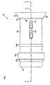
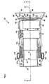
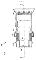
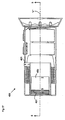
- Figure 1 is a side elevational view of the first preferred embodiment of the manually rechargeable flashlight according to the present invention, with the manually operable external magnet control member in a central position;
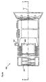
- Figure 2 is a side elevational view similar to Figure 1 , but with the manually operable external magnet control member in a forward position;
- Figure 3 is a side elevational view similar to Figure 1 , but with the manually operable external magnet control member in a rearward position;
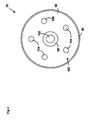
- Figure 4 is an end elevational view of the manually rechargeable flashlight of Figure 1 ;
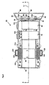
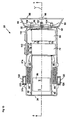
- Figure 5 is a sectional side elevational view of the manually rechargeable flashlight of Figure 1 , taken along section line 5 - 5 of Figure 1 , with the manually operable external magnet control member in a central position;
- Figure 6 is a sectional side elevational view similar to Figure 5 , but also showing the magnetic lines of flux;
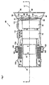
- Figure 7 is a sectional side view elevational similar to Figure 5 , but with the manually operable external magnet control member in a forward position;
- Figure 8 is a sectional side elevational view similar to Figure 7 , but with the manually operable external magnet control member in an extended forward position;
- Figure 9 is a sectional side elevational view similar to Figure 8 , but with the manually operable external magnet control member in a rearward position;
- Figure 10 is a sectional side elevational view similar to Figure 9 , but with the manually operable external magnet control member in an extended rearward position;
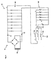
- Figure 11 is a block diagram schematic of the first preferred embodiment manually rechargeable flashlight of Figure 1 , specifically showing the charging circuit;
- Figure 12 is a side elevational view of the second preferred embodiment of the manually rechargeable flashlight according to the present invention, with the manually operable external magnet control member in a rearward position;
- Figure 13 is a side elevational view of the second preferred embodiment of Figure 12 , with the manually operable external magnet control member in a forward position;
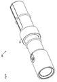
- Figure 14 is a perspective view of the third preferred embodiment of the manually rechargeable flashlight according to the present invention.
- Figure 15 is an enlarged perspective view of the third preferred embodiment of Figure 14 ;
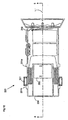
- Figure 16 is a sectional side elevational view of the fourth preferred embodiment of the manually rechargeable flashlight according to the present invention, with the external magnet control member in a neutral position;
- Figure 17 is a sectional side elevational view of the fourth preferred embodiment of the manually rechargeable flashlight of Figure 16 , but with the external magnet control member in a repelling position.
- Figures 1 through 11 illustrate a preferred embodiment of the manually rechargeable flashlight according to the present invention
- Figures 12 and 13 illustrate a second preferred embodiment of the manually rechargeable flashlight according to the present invention
- Figures 14 and 15 illustrate a third preferred embodiment of the manually rechargeable flashlight according to the present invention
- Figures 16 and 17 illustrate a fourth preferred embodiment of the manually rechargeable flashlight according to the present invention.
- the manually rechargeable flashlight 20 comprises a main housing 30 preferably made from plastic and shaped and dimensioned to the properly grip by moat human hands.
- the main housing 30 has a front end 32 and a back end 34 is preferably cylindrical in shape and defines longitudinal axis "L", and has a diameter of about two inches and a length of perhaps about five inches.
- the exact size and shape of the main housing 30 is not germane to the present invention, although most of the components of the manually rechargeable flashlight 20 according to the present invention must fit properly inside the main housing 30.
- an elongate tube 40 Disposed within the main housing 30 is an elongate tube 40, a free-sliding permanent magnet 50 disposed within the elongate tube 40, a coil 60 of electrically conductive wire wrapped around the center portion of the elongate tube 40, a rectifier 70 that is powered by the coil 60, and a plurality of capacitors 80 that are charged by the rectifier 70.
- the electrical energy stored in the capacitors 80 are used to illuminate a plurality of light emitting diodes 100.
- An external magnet control member comprising a magnet control ring 120 is disposed circumferentially around a central portion of the main housing 30 for free sliding movement between a forward stop ring 31a and a rearward stop ring 31b that are integrally formed on the main housing 30.
- the magnet control ring 120 has two bar magnets 122,124 (preferably also rare earth magnets) oriented longitudinally in parallel with the longitudinal axis "L". The north end of each of the bar magnets 122,124 is oriented towards the back end 34 of the main housing 30 while the south end of each of the bar magnets 122,124 is oriented towards the front end 32 of the main housing 30.
- a reflector housing 90 that houses the plurality of light emitting diodes 100 (LEDs), specifically a central light emitting diode 102 and five peripheral light emitting diodes 104.
- the reflector housing 90 has a back wall portion 92 that is mounted on the front end 32 of the main housing 30, a sloped peripheral wall portion 94 extending outwardly from the back wall portion 92, and a clear plastic or glass lens 96 that is generally flat and of substantially constant thickness, but with a central focusing lens portion 98 therein.
- the central focusing lens portion 98 is used to focus the light from the central light emitting diode 102 onto a relatively small area.
- a reflector 99 having six appropriately located paraboloid shapes for reflecting light forwardly from the light emitting diodes 100 is disposed within the reflector housing 90 just ahead of the back wall portion 92.
- the elongate tube 40 is close-ended and is secured to the back end 34 of the main housing 30 so as to be oriented generally along the longitudinal axis "L".
- the permanent magnet 50 is disposed in free-sliding relation in the elongate tube 40, so as to move within the interior of the coil 60.
- a rear-earth type magnet in order to maximize the magnetic flux passing through the coil 60.
- the north end of the permanent magnet 50 is oriented towards the front end 32 of the main housing 30 while the south end of the permanent magnet 50 is oriented towards the back end 34 of the main housing 30. In this manner, the permanent magnet 50 is oriented oppositely to the bar magnets 122, 124.
- the magnetic lines of flux are completed in regular loops (as can be seen in Figure 6 ) when the permanent magnet 50 is in a generally central position in the elongate tube 40.
- the permanent magnet 50 is therefore essentially carried by the bar magnets 122,124.
- the magnet control ring 120 containing the bar magnets 122, 124
- the permanent magnet 50 is magnetically drawn by the bar magnets 122,124. Accordingly, the permanent magnet 50 follows the movement of the magnet control ring 120, as will be discussed in greater detail subsequently.
- the electrical output of the generator 60 is connected via wires 66 to the bridge rectifier 70 that is also mounted within the housing.
- the bridge rectifier 70 as shown in the schematic ( Figure 4 ) is a conventional bridge rectifier 70 comprising four diodes 72. Further, two additional diodes 74 are used to filter out spike voltages.
- the rectifier 70 is electrically connected via wires 76 to the bank of eight capacitors 80 connected together in parallel. It has been found that tantalum type capacitors 80 having a capacity of 1.0 farad at 5.5 VDC are suitable and store a suitable amount of electrical power for powering the various light emitting diodes 100. Alternatively, if a higher voltage is required, the eight capacitors 80 can also be arranged in four pairs, with the capacitors 80 in each pair connected together in series one with the other, and with the four groups connected together in parallel.
- the light emitting diodes 100 are connected in parallel with the capacitor bank 80 with an intensity switch 110 (single-pole triple-throw switch) that is used to select either a high intensity setting through a 20 ohm resistor 114, a medium intensity setting through a 200 ohm resistor 116, or a low intensity setting through a 470 ohm resistor 118. These resistor values have been found to be useful, but other resistor values may also be readily suitable.
- a mode switch 112 (single-pole double-throw switch) is connected in series with the intensity switch 110 and is used to choose either the central light emitting diode 102 or the five peripheral light emitting diodes 104. In the event that the central light emitting diode 102 is chosen, it will illuminate a smaller area and will also drain the capacitor bank at a level one-fifth of that as the five peripheral light emitting diodes 104.
- FIG. 5 the magnet control ring 120 is in a central position between the forward stop ring 31a and the rearward stop ring 31b on the main housing 30.
- the magnet control ring 120 has been moved forwardly to a forward position whereat it abuts against the forward stop ring 31a.
- the permanent magnet 50 is also moved forwardly due to the influence of the magnetic flux from the bar magnets 122,124.
- the permanent magnet 50 travels beyond its position in Figure 7 , due to the momentum of the permanent magnet 50.
- the faster the magnet control ring 120 is moved the faster the permanent magnet 50 is traveling when it reaches the forward position as shown in Figure 7 , thus the more momentum it has and the farther it travels to its extended forward position.
- the magnet control ring 120 is then moved rearwardly through its central position to a rearward position as is shown in Figure 9 , whereat it abuts against the rearward stop ring 31b.
- the permanent magnet 50 is also moved rearwardly due to the influence of the magnetic flux from the bar magnets 122,124. As can be seen in Figure 10 , the permanent magnet 50 travels beyond its position in Figure 9 , due to the momentum of the permanent magnet 50, to its extended rearward position.
- the magnet control ring 120 is then moved back to its central position. This overall movement pattern is repeated so as to define an oscillatory motion of the magnet control ring 120 and to thereby cause an extended oscillatory motion of the permanent magnet 50.
- the motion of the permanent magnet 50 with respect to the coil 60 causes electricity to be generated by the coil 60.
- the extended oscillatory motion of the permanent magnet 50 as described above, as caused by the movement of the magnet control ring 120, a sufficient amount of electricity to charge the capacitors 80 in the capacitor bank is generated quite readily with only a minor amount of mechanical effort.
- the magnet control ring 120 could be replaced by a cylindrical outer casing that slides longitudinally along the main housing between a forward position and a rearward position.
- FIGS 12 and 13 show a second preferred embodiment of the manually rechargeable flashlight of the present invention, as indicated by general reference numeral 220.
- the manually rechargeable flashlight 220 is similar to the first preferred embodiment manually rechargeable flashlight 20, except that the permanent magnet 250 is oriented in the opposite direction of the permanent magnet 50 in the first preferred embodiment. Accordingly, the north pole of the permanent magnet 250 faces the back end 234 of the main housing 230 and the south pole of the permanent magnet 250 faces the front end 232 of the main housing 230.
- the external magnet control member which more specifically comprises a magnet control ring
- the north and south poles of the magnet control ring 221 repel the north and south poles, respectively, of the permanent magnet 250. Accordingly, the permanent magnet 250 is quickly forced to a forward position.
- the magnet control ring 221 is moved forwardly, as shown in Figure 13
- the north and south poles of the magnet control ring 221 repel the north and south poles, respectively, of the permanent magnet 250. Accordingly, the permanent magnet 250 is quickly forced to a rearward position.
- FIGS 14 and 15 show a second preferred embodiment of the manually rechargeable flashlight of the present invention, as indicated by general reference numeral 320.
- the manually rechargeable flashlight 320 is similar to the second preferred embodiment manually rechargeable flashlight 220, except that the magnet control ring 321 has several bar magnets 322 mounted therein, so as to provide an increased magnetic force acting on the permanent magnet 350 in the elongate tube 340.
- FIGS 16 and 17 show a third preferred embodiment of the manually rechargeable flashlight of the present invention, as indicated by general reference numeral 420.
- the manually rechargeable flashlight 420 is similar to the second preferred embodiment manually rechargeable flashlight 220, except that the magnet control ring 221 has been replaced by an external magnet control member comprising a magnet control ring 421 mounted on the main housing 430 for movement in a transverse direction to the longitudinal axis "L" between a neutral position, as is shown in Figure 16 , and a repelling position, as is shown in Figure 17 .
- the magnet control ring 421 comprises at least one bar magnet oriented longitudinally in parallel with the longitudinal axis "L".
- a manually rechargeable flashlight comprises a main housing with an external magnet control member disposed circumferentially around the main housing for free sliding movement along the longitudinal axis "L" between a forward position and a rearward position.
- the external magnet control member has at least one bar magnet oriented longitudinally in parallel with the longitudinal axis "L".
- a switch is for turning on and off the least one light emitting diode.
- An elongate tube is disposed within the main housing.
- a coil of electrically conductive wire is disposed around the main housing, and electrically connected to the at least one capacitor or rechargeable battery.
- a permanent magnet is disposed in free-sliding relation in the elongate tube so as to move within the interior of the coil, and is oriented with its north pole in the opposite direction along the longitudinal axis "L” as the has at least one bar magnet in the external magnet control member.
- the external magnet control member is moved along the longitudinal axis "L” between the forward position and a rearward position, the permanent magnet is moved along the longitudinal axis "L” generally with the external magnet control member.
- the permanent magnet is oriented with its north pole in the same direction along the longitudinal axis "L” as the has at least one bar magnet in the external magnet control member, and when the external magnet control member is moved along the longitudinal axis "L” between the forward position and a rearward position, the permanent magnet is moved along the longitudinal axis "L” in an opposite direction to the external magnet control member.
Landscapes
- Engineering & Computer Science (AREA)
- Power Engineering (AREA)
- General Engineering & Computer Science (AREA)
- Life Sciences & Earth Sciences (AREA)
- Sustainable Development (AREA)
- Sustainable Energy (AREA)
- Charge And Discharge Circuits For Batteries Or The Like (AREA)
Claims (9)
- Manuell wiederaufladbare Taschenlampe, umfassend:- ein eine Längsachse "L" definierendes Hauptgehäuse;- ein externes Magnet-Steuerelement, das derart umlaufend am Hauptgehäuse angeordnet ist, dass es entlang der Längsachse "L" frei zwischen einer vorderen und einer hinteren Stellung gleiten kann;- wobei das externe Magnet-Steuerelement mindestens einen Stabmagneten enthält, der in Längsrichtung parallel zur Längsachse "L" ausgerichtet ist;- mindestens eine Leuchtdiode;- eine Speichereinrichtung zum Speichern elektrischer Energie und zur Versorgung der mindestens einen Leuchtdiode mit der elektrischen Energie;- ein Schaltmittel zum Ein- und Ausschalten der mindestens einen Leuchtdiode;- ein innerhalb des Hauptgehäuses angeordnetes längliches Rohr;- eine Spule aus elektrisch leitendem Draht, der um das Hauptgehäuse verläuft und elektrisch mit der Speichereinrichtung verbunden ist; und- einen Permanentmagneten, der in dem länglichen Rohr derart frei gleitend angeordnet ist, dass er innerhalb der Spule bewegbar ist, und der mit seinem Nordpol entlang der Längsachse "L" entgegengesetzt der Richtung des im externen Magnet-Steuerelement angeordneten, mindestens einen Stabmagnets ausgerichtet ist;- wobei der Permanentmagnet bei Bewegung des externen Magnet-Steuerelementes entlang der Längsachse "L" zwischen der vorderen Position und einer hinteren Position entlang dieser Längsachse "L" im allgemeinen mit dem externen Magnet-Steuerelement bewegt wird.
- Manuell wiederaufladbare Taschenlampe nach Anspruch 1, wobei das externe Magnet-Steuerelement einen Magnet-Steuerring umfasst.
- Manuell wiederaufladbare Taschenlampe nach Anspruch 1, wobei die Speichereinrichtung zum Speichern von elektrischer Energie mindestens einen Kondensator oder mindestens eine wiederaufladbare Batterie umfasst.
- Manuell wiederaufladbare Taschenlampe, umfassend- ein eine Längsachse "L" definierendes Hauptgehäuse;- ein externes Magnet-Steuerelement, das derart umlaufend am Hauptgehäuse angeordnet ist, dass es entlang der Längsachse "L" frei zwischen einer vorderen und einer hinteren Stellung gleiten kann;- wobei das externe Magnet-Steuerelement mindestens einen Stabmagneten enthält, der in Längsrichtung parallel zur Längsachse "L" so ausgerichtet ist, dass sein Nordpol zur Vorderseite weist;- mindestens eine Leuchtdiode;- eine Speichereinrichtung zum Speichern elektrischer Energie und zur Versorgung der mindestens einen Leuchtdiode mit der elektrischen Energie;- ein Schaltmittel zum Ein- und Ausschalten der mindestens einen Leuchtdiode;- ein innerhalb des Hauptgehäuses angeordnetes längliches Rohr;- eine Spule aus elektrisch leitendem Draht, der um das Hauptgehäuse verläuft und elektrisch mit der Speichereinrichtung verbunden ist; und- einen Permanentmagneten, der in dem länglichen Rohr derart frei gleitend angeordnet ist, dass er innerhalb der Spule bewegbar ist, und der mit seinem Nordpol entlang der Längsachse "L" in die gleiche Richtung wie der im externen Magnet-Steuerelement angeordnete, mindestens eine Stabmagnet ausgerichtet ist;- wobei der Permanentmagnet bei Bewegung des externen Magnet-Steuerelementes entlang der Längsachse "L" zwischen der vorderen Position und einer hinteren Position entlang dieser Längsachse "L" in einer zum externen Magnet-Steuerelement entgegengesetzten Richtung bewegt wird.
- Manuell wiederaufladbare Taschenlampe nach Anspruch 4, wobei das externe Magnet-Steuerelement einen Magnet-Steuerring umfasst.
- Manuell wiederaufladbare Taschenlampe nach Anspruch 4, wobei die Speichereinrichtung zum Speichern von elektrischer Energie mindestens einen Kondensator oder mindestens eine wiederaufladbare Batterie umfasst.
- Eine manuell wiederaufladbare Taschenlampe, umfassend:- ein eine Längsachse "L" definierendes Hauptgehäuse;- ein externes Magnet-Steuerelement, das derart am Hauptgehäuse angeordnet ist, dass es sich zwischen einer neutralen und einer Rückstoß-Stellung bewegen kann;- wobei das externe Magnet-Steuerelement mindestens einen Stabmagneten enthält, der in Längsrichtung parallel zur Längsachse "L" ausgerichtet ist;- mindestens eine Leuchtdiode;- eine Speichereinrichtung zum Speichern elektrischer Energie und zur Versorgung der mindestens einen Leuchtdiode mit der elektrischen Energie;- ein Schaltmittel zum Ein- und Ausschalten der mindestens einen Leuchtdiode;- ein innerhalb des Hauptgehäuses angeordnetes längliches Rohr;- eine Spule aus elektrisch leitendem Draht, der um das Hauptgehäuse verläuft und elektrisch mit der Speichereinrichtung verbunden ist; und- einen Permanentmagneten, der in dem länglichen Rohr derart frei gleitend angeordnet ist, dass er innerhalb der Spule bewegbar ist;- wobei der Permanentmagnet, wenn das externe Magnet-Steuerelement in der neutralen Stellung ist, nahe dem externen Magnet-Steuerelement ist, und der Permanentmagnet, wenn das externe Magnet-Steuerelement in der Rückstoß-Stellung ist, vom externen Magnet-Steuerelement weg gestoßen wird.
- Manuell wiederaufladbare Taschenlampe nach Anspruch 7, wobei das externe Magnet-Steuerelement einen Magnet-Steuerring umfasst.
- Manuell wiederaufladbare Taschenlampe nach Anspruch 7, wobei die Speichereinrichtung zum Speichern von elektrischer Energie mindestens einen Kondensator oder mindestens eine wiederaufladbare Batterie umfasst.
Applications Claiming Priority (2)
| Application Number | Priority Date | Filing Date | Title |
|---|---|---|---|
| CA2534674A CA2534674C (en) | 2005-01-25 | 2006-01-25 | Manually rechargeable flashlight |
| PCT/CA2007/000092 WO2007085078A1 (en) | 2006-01-25 | 2007-01-25 | Manually rechargeable flash light |
Publications (3)
| Publication Number | Publication Date |
|---|---|
| EP2002174A1 EP2002174A1 (de) | 2008-12-17 |
| EP2002174A4 EP2002174A4 (de) | 2010-06-09 |
| EP2002174B1 true EP2002174B1 (de) | 2012-10-03 |
Family
ID=38308797
Family Applications (1)
| Application Number | Title | Priority Date | Filing Date |
|---|---|---|---|
| EP07719344A Active EP2002174B1 (de) | 2006-01-25 | 2007-01-25 | Manuell wiederaufladbare taschenlampe |
Country Status (2)
| Country | Link |
|---|---|
| EP (1) | EP2002174B1 (de) |
| WO (1) | WO2007085078A1 (de) |
Cited By (1)
| Publication number | Priority date | Publication date | Assignee | Title |
|---|---|---|---|---|
| RU168301U1 (ru) * | 2016-08-23 | 2017-01-30 | федеральное государственное автономное образовательное учреждение высшего образования "Южный федеральный университет" (Южный федеральный университет) | Оптический извещатель |
Families Citing this family (3)
| Publication number | Priority date | Publication date | Assignee | Title |
|---|---|---|---|---|
| WO2009021547A1 (de) * | 2007-08-10 | 2009-02-19 | Lightlite Gmbh | Energieversorgungsvorrichtung für el-leuchtschnüre |
| CN102374387A (zh) * | 2011-10-29 | 2012-03-14 | 常熟市董浜镇华进电器厂 | 一种可充电式触摸开关节能手电筒 |
| TWM436994U (en) * | 2012-03-21 | 2012-09-01 | Guangdong Jetfast Portable Lighting Co Ltd | Illumination and moveable charging device with touch switch |
Family Cites Families (4)
| Publication number | Priority date | Publication date | Assignee | Title |
|---|---|---|---|---|
| US4315301A (en) * | 1978-10-16 | 1982-02-09 | Jimena Carlos L | Generator flashlight |
| US5975714A (en) * | 1997-06-03 | 1999-11-02 | Applied Innovative Technologies, Incorporated | Renewable energy flashlight |
| KR20030002854A (ko) * | 2001-06-29 | 2003-01-09 | 조안순 | 발전수단이 구비된 손전등 |
| US6729744B2 (en) * | 2002-03-29 | 2004-05-04 | Pat Y. Mah | Faraday flashlight |
-
2007
- 2007-01-25 EP EP07719344A patent/EP2002174B1/de active Active
- 2007-01-25 WO PCT/CA2007/000092 patent/WO2007085078A1/en not_active Ceased
Cited By (1)
| Publication number | Priority date | Publication date | Assignee | Title |
|---|---|---|---|---|
| RU168301U1 (ru) * | 2016-08-23 | 2017-01-30 | федеральное государственное автономное образовательное учреждение высшего образования "Южный федеральный университет" (Южный федеральный университет) | Оптический извещатель |
Also Published As
| Publication number | Publication date |
|---|---|
| EP2002174A1 (de) | 2008-12-17 |
| WO2007085078A1 (en) | 2007-08-02 |
| EP2002174A4 (de) | 2010-06-09 |
Similar Documents
| Publication | Publication Date | Title |
|---|---|---|
| US5975714A (en) | Renewable energy flashlight | |
| US6220719B1 (en) | Renewable energy flashlight | |
| US6729744B2 (en) | Faraday flashlight | |
| US7404651B2 (en) | Renewable energy flashlight | |
| US5584561A (en) | Lighting device for a bicycle | |
| US8723348B2 (en) | Battery assembly with kinetic energy-based recharging | |
| EP2002174B1 (de) | Manuell wiederaufladbare taschenlampe | |
| US4709176A (en) | Magnetic battery | |
| US7234833B2 (en) | Work light | |
| US20110278860A1 (en) | Fishing reel power generator | |
| GB2311171A (en) | Device for generating electricity from vibrations | |
| CA2534674C (en) | Manually rechargeable flashlight | |
| US20020030994A1 (en) | Fuel cell powered portable light | |
| RU2234638C2 (ru) | Портативный электрический фонарь | |
| US5816689A (en) | Apparatus and associated method for creating a broad area of illumination | |
| CN2616792Y (zh) | 再生免电池便携式磁能环保发光器 | |
| KR200197905Y1 (ko) | 자가발전이 가능한 휴대형 발광장치 | |
| KR20020031784A (ko) | 자가발전기가 내장된 손전등 겸용 신호봉 | |
| WO2002042682A1 (en) | Hand powered electric flashlight using light emitting diodes | |
| KR200302495Y1 (ko) | 자가 발전 기능을 갖는 손전등 | |
| CN2594620Y (zh) | 磁能环保发光器 | |
| KR200287862Y1 (ko) | 발전식 손전등 | |
| CN203322755U (zh) | 多功能手电筒 | |
| JP3176474U (ja) | 照光機能付き筆記具 | |
| CN201028318Y (zh) | 手压手电 |
Legal Events
| Date | Code | Title | Description |
|---|---|---|---|
| PUAI | Public reference made under article 153(3) epc to a published international application that has entered the european phase |
Free format text: ORIGINAL CODE: 0009012 |
|
| 17P | Request for examination filed |
Effective date: 20080826 |
|
| AK | Designated contracting states |
Kind code of ref document: A1 Designated state(s): AT BE BG CH CY CZ DE DK EE ES FI FR GB GR HU IE IS IT LI LT LU LV MC NL PL PT RO SE SI SK TR |
|
| AX | Request for extension of the european patent |
Extension state: AL BA HR MK RS |
|
| R17P | Request for examination filed (corrected) |
Effective date: 20080826 |
|
| A4 | Supplementary search report drawn up and despatched |
Effective date: 20100511 |
|
| GRAP | Despatch of communication of intention to grant a patent |
Free format text: ORIGINAL CODE: EPIDOSNIGR1 |
|
| GRAS | Grant fee paid |
Free format text: ORIGINAL CODE: EPIDOSNIGR3 |
|
| GRAA | (expected) grant |
Free format text: ORIGINAL CODE: 0009210 |
|
| AK | Designated contracting states |
Kind code of ref document: B1 Designated state(s): AT BE BG CH CY CZ DE DK EE ES FI FR GB GR HU IE IS IT LI LT LU LV MC NL PL PT RO SE SI SK TR |
|
| AX | Request for extension of the european patent |
Extension state: AL BA HR MK RS |
|
| REG | Reference to a national code |
Ref country code: GB Ref legal event code: FG4D |
|
| REG | Reference to a national code |
Ref country code: AT Ref legal event code: REF Ref document number: 578146 Country of ref document: AT Kind code of ref document: T Effective date: 20121015 Ref country code: CH Ref legal event code: EP |
|
| REG | Reference to a national code |
Ref country code: IE Ref legal event code: FG4D |
|
| REG | Reference to a national code |
Ref country code: DE Ref legal event code: R096 Ref document number: 602007025852 Country of ref document: DE Effective date: 20121129 |
|
| REG | Reference to a national code |
Ref country code: AT Ref legal event code: MK05 Ref document number: 578146 Country of ref document: AT Kind code of ref document: T Effective date: 20121003 |
|
| PG25 | Lapsed in a contracting state [announced via postgrant information from national office to epo] |
Ref country code: SI Free format text: LAPSE BECAUSE OF FAILURE TO SUBMIT A TRANSLATION OF THE DESCRIPTION OR TO PAY THE FEE WITHIN THE PRESCRIBED TIME-LIMIT Effective date: 20121003 |
|
| REG | Reference to a national code |
Ref country code: NL Ref legal event code: VDEP Effective date: 20121003 |
|
| REG | Reference to a national code |
Ref country code: LT Ref legal event code: MG4D |
|
| PG25 | Lapsed in a contracting state [announced via postgrant information from national office to epo] |
Ref country code: ES Free format text: LAPSE BECAUSE OF FAILURE TO SUBMIT A TRANSLATION OF THE DESCRIPTION OR TO PAY THE FEE WITHIN THE PRESCRIBED TIME-LIMIT Effective date: 20130114 Ref country code: IS Free format text: LAPSE BECAUSE OF FAILURE TO SUBMIT A TRANSLATION OF THE DESCRIPTION OR TO PAY THE FEE WITHIN THE PRESCRIBED TIME-LIMIT Effective date: 20130203 Ref country code: SE Free format text: LAPSE BECAUSE OF FAILURE TO SUBMIT A TRANSLATION OF THE DESCRIPTION OR TO PAY THE FEE WITHIN THE PRESCRIBED TIME-LIMIT Effective date: 20121003 Ref country code: FI Free format text: LAPSE BECAUSE OF FAILURE TO SUBMIT A TRANSLATION OF THE DESCRIPTION OR TO PAY THE FEE WITHIN THE PRESCRIBED TIME-LIMIT Effective date: 20121003 Ref country code: NL Free format text: LAPSE BECAUSE OF FAILURE TO SUBMIT A TRANSLATION OF THE DESCRIPTION OR TO PAY THE FEE WITHIN THE PRESCRIBED TIME-LIMIT Effective date: 20121003 Ref country code: LT Free format text: LAPSE BECAUSE OF FAILURE TO SUBMIT A TRANSLATION OF THE DESCRIPTION OR TO PAY THE FEE WITHIN THE PRESCRIBED TIME-LIMIT Effective date: 20121003 |
|
| PG25 | Lapsed in a contracting state [announced via postgrant information from national office to epo] |
Ref country code: PL Free format text: LAPSE BECAUSE OF FAILURE TO SUBMIT A TRANSLATION OF THE DESCRIPTION OR TO PAY THE FEE WITHIN THE PRESCRIBED TIME-LIMIT Effective date: 20121003 Ref country code: PT Free format text: LAPSE BECAUSE OF FAILURE TO SUBMIT A TRANSLATION OF THE DESCRIPTION OR TO PAY THE FEE WITHIN THE PRESCRIBED TIME-LIMIT Effective date: 20130204 Ref country code: CY Free format text: LAPSE BECAUSE OF FAILURE TO SUBMIT A TRANSLATION OF THE DESCRIPTION OR TO PAY THE FEE WITHIN THE PRESCRIBED TIME-LIMIT Effective date: 20121003 Ref country code: BE Free format text: LAPSE BECAUSE OF FAILURE TO SUBMIT A TRANSLATION OF THE DESCRIPTION OR TO PAY THE FEE WITHIN THE PRESCRIBED TIME-LIMIT Effective date: 20121003 Ref country code: GR Free format text: LAPSE BECAUSE OF FAILURE TO SUBMIT A TRANSLATION OF THE DESCRIPTION OR TO PAY THE FEE WITHIN THE PRESCRIBED TIME-LIMIT Effective date: 20130104 Ref country code: LV Free format text: LAPSE BECAUSE OF FAILURE TO SUBMIT A TRANSLATION OF THE DESCRIPTION OR TO PAY THE FEE WITHIN THE PRESCRIBED TIME-LIMIT Effective date: 20121003 |
|
| PG25 | Lapsed in a contracting state [announced via postgrant information from national office to epo] |
Ref country code: AT Free format text: LAPSE BECAUSE OF FAILURE TO SUBMIT A TRANSLATION OF THE DESCRIPTION OR TO PAY THE FEE WITHIN THE PRESCRIBED TIME-LIMIT Effective date: 20121003 |
|
| PG25 | Lapsed in a contracting state [announced via postgrant information from national office to epo] |
Ref country code: BG Free format text: LAPSE BECAUSE OF FAILURE TO SUBMIT A TRANSLATION OF THE DESCRIPTION OR TO PAY THE FEE WITHIN THE PRESCRIBED TIME-LIMIT Effective date: 20130103 Ref country code: DK Free format text: LAPSE BECAUSE OF FAILURE TO SUBMIT A TRANSLATION OF THE DESCRIPTION OR TO PAY THE FEE WITHIN THE PRESCRIBED TIME-LIMIT Effective date: 20121003 Ref country code: SK Free format text: LAPSE BECAUSE OF FAILURE TO SUBMIT A TRANSLATION OF THE DESCRIPTION OR TO PAY THE FEE WITHIN THE PRESCRIBED TIME-LIMIT Effective date: 20121003 Ref country code: CZ Free format text: LAPSE BECAUSE OF FAILURE TO SUBMIT A TRANSLATION OF THE DESCRIPTION OR TO PAY THE FEE WITHIN THE PRESCRIBED TIME-LIMIT Effective date: 20121003 Ref country code: EE Free format text: LAPSE BECAUSE OF FAILURE TO SUBMIT A TRANSLATION OF THE DESCRIPTION OR TO PAY THE FEE WITHIN THE PRESCRIBED TIME-LIMIT Effective date: 20121003 |
|
| PLBE | No opposition filed within time limit |
Free format text: ORIGINAL CODE: 0009261 |
|
| STAA | Information on the status of an ep patent application or granted ep patent |
Free format text: STATUS: NO OPPOSITION FILED WITHIN TIME LIMIT |
|
| PG25 | Lapsed in a contracting state [announced via postgrant information from national office to epo] |
Ref country code: RO Free format text: LAPSE BECAUSE OF FAILURE TO SUBMIT A TRANSLATION OF THE DESCRIPTION OR TO PAY THE FEE WITHIN THE PRESCRIBED TIME-LIMIT Effective date: 20121003 Ref country code: MC Free format text: LAPSE BECAUSE OF NON-PAYMENT OF DUE FEES Effective date: 20130131 Ref country code: IT Free format text: LAPSE BECAUSE OF FAILURE TO SUBMIT A TRANSLATION OF THE DESCRIPTION OR TO PAY THE FEE WITHIN THE PRESCRIBED TIME-LIMIT Effective date: 20121003 |
|
| REG | Reference to a national code |
Ref country code: CH Ref legal event code: PL |
|
| 26N | No opposition filed |
Effective date: 20130704 |
|
| REG | Reference to a national code |
Ref country code: IE Ref legal event code: MM4A |
|
| PG25 | Lapsed in a contracting state [announced via postgrant information from national office to epo] |
Ref country code: LI Free format text: LAPSE BECAUSE OF NON-PAYMENT OF DUE FEES Effective date: 20130131 Ref country code: CH Free format text: LAPSE BECAUSE OF NON-PAYMENT OF DUE FEES Effective date: 20130131 |
|
| REG | Reference to a national code |
Ref country code: DE Ref legal event code: R097 Ref document number: 602007025852 Country of ref document: DE Effective date: 20130704 |
|
| PG25 | Lapsed in a contracting state [announced via postgrant information from national office to epo] |
Ref country code: IE Free format text: LAPSE BECAUSE OF NON-PAYMENT OF DUE FEES Effective date: 20130125 |
|
| PG25 | Lapsed in a contracting state [announced via postgrant information from national office to epo] |
Ref country code: TR Free format text: LAPSE BECAUSE OF FAILURE TO SUBMIT A TRANSLATION OF THE DESCRIPTION OR TO PAY THE FEE WITHIN THE PRESCRIBED TIME-LIMIT Effective date: 20121003 |
|
| PG25 | Lapsed in a contracting state [announced via postgrant information from national office to epo] |
Ref country code: LU Free format text: LAPSE BECAUSE OF NON-PAYMENT OF DUE FEES Effective date: 20130125 Ref country code: HU Free format text: LAPSE BECAUSE OF FAILURE TO SUBMIT A TRANSLATION OF THE DESCRIPTION OR TO PAY THE FEE WITHIN THE PRESCRIBED TIME-LIMIT; INVALID AB INITIO Effective date: 20070125 |
|
| REG | Reference to a national code |
Ref country code: FR Ref legal event code: PLFP Year of fee payment: 10 |
|
| REG | Reference to a national code |
Ref country code: FR Ref legal event code: PLFP Year of fee payment: 11 |
|
| REG | Reference to a national code |
Ref country code: FR Ref legal event code: PLFP Year of fee payment: 12 |
|
| PGFP | Annual fee paid to national office [announced via postgrant information from national office to epo] |
Ref country code: FR Payment date: 20180731 Year of fee payment: 12 Ref country code: DE Payment date: 20180731 Year of fee payment: 12 |
|
| PGFP | Annual fee paid to national office [announced via postgrant information from national office to epo] |
Ref country code: GB Payment date: 20180731 Year of fee payment: 12 |
|
| REG | Reference to a national code |
Ref country code: DE Ref legal event code: R119 Ref document number: 602007025852 Country of ref document: DE |
|
| GBPC | Gb: european patent ceased through non-payment of renewal fee |
Effective date: 20190125 |
|
| PG25 | Lapsed in a contracting state [announced via postgrant information from national office to epo] |
Ref country code: FR Free format text: LAPSE BECAUSE OF NON-PAYMENT OF DUE FEES Effective date: 20190131 Ref country code: DE Free format text: LAPSE BECAUSE OF NON-PAYMENT OF DUE FEES Effective date: 20190801 |
|
| PG25 | Lapsed in a contracting state [announced via postgrant information from national office to epo] |
Ref country code: GB Free format text: LAPSE BECAUSE OF NON-PAYMENT OF DUE FEES Effective date: 20190125 |