EP2002138B1 - Rotational coupling device - Google Patents
Rotational coupling device Download PDFInfo
- Publication number
- EP2002138B1 EP2002138B1 EP07754729.7A EP07754729A EP2002138B1 EP 2002138 B1 EP2002138 B1 EP 2002138B1 EP 07754729 A EP07754729 A EP 07754729A EP 2002138 B1 EP2002138 B1 EP 2002138B1
- Authority
- EP
- European Patent Office
- Prior art keywords
- hub
- support member
- rotor
- coupling device
- rotational coupling
- Prior art date
- Legal status (The legal status is an assumption and is not a legal conclusion. Google has not performed a legal analysis and makes no representation as to the accuracy of the status listed.)
- Active
Links
Images
Classifications
-
- F—MECHANICAL ENGINEERING; LIGHTING; HEATING; WEAPONS; BLASTING
- F16—ENGINEERING ELEMENTS AND UNITS; GENERAL MEASURES FOR PRODUCING AND MAINTAINING EFFECTIVE FUNCTIONING OF MACHINES OR INSTALLATIONS; THERMAL INSULATION IN GENERAL
- F16D—COUPLINGS FOR TRANSMITTING ROTATION; CLUTCHES; BRAKES
- F16D27/00—Magnetically- or electrically- actuated clutches; Control or electric circuits therefor
- F16D27/10—Magnetically- or electrically- actuated clutches; Control or electric circuits therefor with an electromagnet not rotating with a clutching member, i.e. without collecting rings
- F16D27/118—Magnetically- or electrically- actuated clutches; Control or electric circuits therefor with an electromagnet not rotating with a clutching member, i.e. without collecting rings with interengaging jaws or gear teeth
-
- F—MECHANICAL ENGINEERING; LIGHTING; HEATING; WEAPONS; BLASTING
- F16—ENGINEERING ELEMENTS AND UNITS; GENERAL MEASURES FOR PRODUCING AND MAINTAINING EFFECTIVE FUNCTIONING OF MACHINES OR INSTALLATIONS; THERMAL INSULATION IN GENERAL
- F16D—COUPLINGS FOR TRANSMITTING ROTATION; CLUTCHES; BRAKES
- F16D27/00—Magnetically- or electrically- actuated clutches; Control or electric circuits therefor
- F16D27/10—Magnetically- or electrically- actuated clutches; Control or electric circuits therefor with an electromagnet not rotating with a clutching member, i.e. without collecting rings
- F16D27/108—Magnetically- or electrically- actuated clutches; Control or electric circuits therefor with an electromagnet not rotating with a clutching member, i.e. without collecting rings with axially movable clutching members
- F16D27/112—Magnetically- or electrically- actuated clutches; Control or electric circuits therefor with an electromagnet not rotating with a clutching member, i.e. without collecting rings with axially movable clutching members with flat friction surfaces, e.g. discs
-
- F—MECHANICAL ENGINEERING; LIGHTING; HEATING; WEAPONS; BLASTING
- F16—ENGINEERING ELEMENTS AND UNITS; GENERAL MEASURES FOR PRODUCING AND MAINTAINING EFFECTIVE FUNCTIONING OF MACHINES OR INSTALLATIONS; THERMAL INSULATION IN GENERAL
- F16D—COUPLINGS FOR TRANSMITTING ROTATION; CLUTCHES; BRAKES
- F16D67/00—Combinations of couplings and brakes; Combinations of clutches and brakes
- F16D67/02—Clutch-brake combinations
-
- F—MECHANICAL ENGINEERING; LIGHTING; HEATING; WEAPONS; BLASTING
- F16—ENGINEERING ELEMENTS AND UNITS; GENERAL MEASURES FOR PRODUCING AND MAINTAINING EFFECTIVE FUNCTIONING OF MACHINES OR INSTALLATIONS; THERMAL INSULATION IN GENERAL
- F16D—COUPLINGS FOR TRANSMITTING ROTATION; CLUTCHES; BRAKES
- F16D2121/00—Type of actuator operation force
- F16D2121/18—Electric or magnetic
- F16D2121/20—Electric or magnetic using electromagnets
- F16D2121/22—Electric or magnetic using electromagnets for releasing a normally applied brake
-
- F—MECHANICAL ENGINEERING; LIGHTING; HEATING; WEAPONS; BLASTING
- F16—ENGINEERING ELEMENTS AND UNITS; GENERAL MEASURES FOR PRODUCING AND MAINTAINING EFFECTIVE FUNCTIONING OF MACHINES OR INSTALLATIONS; THERMAL INSULATION IN GENERAL
- F16D—COUPLINGS FOR TRANSMITTING ROTATION; CLUTCHES; BRAKES
- F16D2129/00—Type of operation source for auxiliary mechanisms
- F16D2129/06—Electric or magnetic
- F16D2129/065—Permanent magnets
Definitions
- This invention relates to rotational coupling devices such as brakes and clutches and, in particular, to a rotational coupling device that provides enhanced torque transfer characteristics through an inventive coupling arrangements of components within the device.
- Rotational coupling devices such as clutches and brakes are used to control transfer of torque between rotational bodies.
- One type of conventional device is illustrated in U.S. Patent Nos-5,119,918 , 5,285,882 and 5,971,121 .
- This device includes a rotor that is coupled to an input shaft for rotation with the input shaft about a rotational axis.
- a field shell is also disposed about the input shaft on one side of the rotor and is fixed against rotation.
- the field shell defines radially spaced, axially extending inner and outer poles between which an electrical conductor is disposed, facing the rotor.
- a brake plate is coupled to the field shell and axially spaced from the field shell. The brake plate is disposed on a side of the rotor opposite the conductor.
- An armature coupled to an output member is disposed on the same side of the rotor as the brake plate and is disposed axially between the rotor and the brake plate.
- the armature is coupled to an output member by a plurality of leaf springs. Energizing the conductor produces a magnetic circuit in the field shell, rotor and armature that draws the armature into engagement with the rotor and couples the input shaft and output member together for rotation. Upon deenergization of the conductor, the leaf springs draw the armature out of engagement with the rotor and into engagement with the brake plate to brake the armature and output member.
- Permanent magnets coupled to the brake plate are also used to create another magnetic circuit between the brake plate, the field shell and the armature to assist the leaf springs in braking the armature and output member.
- Support members such as spacers used to hold the components of the device in assembled relation limit clearance for the input shaft thereby reducing the amount of engagement between the input shaft and device components and reducing torque transfer.
- conventional support members are often coupled to the input shaft or other through a key/keyway arrangement. Although this arrangements is satisfactory for its intended purpose, it requires precise alignment with the key/keyway of the rotor.
- the inventors herein have recognized a need for a rotational coupling device that will minimize and/or eliminate one or more of the above-identified deficiencies.
- US 5,285,882 discloses a clutch comprising an input hub keyed to a drive shaft, a spacer telescoped into and keyed to the input hub.
- the present invention provides a rotational coupling device.
- a rotational coupling device in accordance with the present invention includes a rotor coupled to an input shaft for rotation therewith.
- the input shaft is disposed about a rotational axis.
- the rotor has a hub defining a central bore into which the input shaft extends.
- the device also includes an armature disposed about the axis.
- the armature is coupled to an output member and configured for selective engagement with the rotor.
- the device further includes a support member disposed about the axis.
- One of the hub and the support member defines a notch disposed in a first axial end face of the one of the hub and the support member.
- Another of the hub and the support member defines an axially projecting lug on a first axial end of the another of the hub and the support member configured to be received within the notch thereby rotatably coupling the support member and the rotor.
- a rotational coupling device in accordance with the present invention represents an improvement over conventional devices.
- the inventive device By coupling support members such as spacers or pulley hubs to the rotor in an axial direction, the inventive device enables greater clearance for the input shaft. As a result, more of the shaft can be coupled to the rotor for increased torque transfer and the clutch can be used in a greater variety of applications.
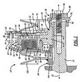
- Figure 1 is a partial cross-sectional view of a rotational coupling device in accordance with one embodiment of the present invention.
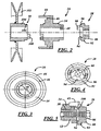
- Figure 2 is an exploded cross-sectional view of several components of the rotational coupling device of Figure 1 .
- Figure 3 is a plan view of one of the components of the rotational coupling device of Figure 1 .
- Figure 4 is a plan view of another one of the components of the rotational coupling device of Figure 1 .
- Figure 5 is an enlarged cross-sectional view of a portion of a rotational coupling device in accordance with another embodiment of the present invention.
- Figure 6 is an enlarged cross-sectional view of a portion of a rotational coupling device in accordance with another embodiment of the present invention.
- Figure 7 is an enlarged cross-sectional view of a portion of a rotational coupling device in accordance with another embodiment of the present invention.
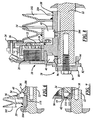
- Figure 8 is a partial cross-sectional view of a rotational coupling device in accordance with another embodiment of the present invention.
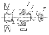
- Figure 9 is an exploded cross-sectional view of several components of a rotational coupling device in accordance with another embodiment of the present invention.
- Figure 1 illustrates a rotational coupling device 10 in accordance with one embodiment of the present invention.
- Device 10 functions as a clutch to selectively transfer torque from an input shaft 12 to an output member 14.
- Device 10 also functions as a brake on output member 14 when torque is not being transferred to output member 14.
- Device 10 may be provided for use in a riding lawnmower or similar device. It will be understood by those of ordinary skill in the art, however, that device 10 may be used in a wide variety of applications requiring a clutch or brake.
- Device 10 may include a rotor 16, a field shell 18, an electrical conduction assembly 20, an armature 22, a brake pole 24, one or more permanent magnets 26 and one or more support members such as spacer 28 or pulley hub 30.
- Input shaft 12 provides a source of torque for driving output member 14.
- Shaft 12 may be made from conventional metals and metal alloys and may be solid or tubular. Shaft 12 is centered about a rotational axis 32 and is driven by an engine, electric motor or other conventional power source. In the illustrated embodiment input shaft 12 is inserted into device 10 on a side of device 10 opposite output member 14.
- Output member 14 transfers torque to a driven device such as a lawnmower blade.
- Member 14 may comprise a conventional pulley around which a torque transmitting belt is wound and coupled to the driven device.
- Rotor 16 is provided for selective engagement with armature 22 to transmit torque between input shaft 12 and output member 14.
- Rotor 16 is disposed about axis 32 and is coupled to input shaft 12 for rotation therewith.
- Rotor 16 may be made from conventional metals and metal alloys and includes a hub 34 and a rotor disc 36.
- Hub 34 is tubular and defines a central bore into which input shaft 12 extends.
- Hub 34 includes a radially inwardly extending key 38 configured to be received within the keyway of input shaft 12. At either axial end, hub 34 abuts against and supports bearings 40, 42. At its radially outer diameter, hub 34 defines an axially extending inner rotor pole 44. Hub 34 further defines an axially extending recess 46 radially inwardly of pole 44 for a purpose described hereinbelow.
- hub 34 may include one or more notches 48 disposed in either axial end face of hub 34 for a purpose discussed hereinbelow.
- hub 34 may include a pair of notches 48 in either end face diametrically opposite one another. If should be understood, however, that the number, shape and orientation of notches 48 may vary without departing from the spirit of the present invention. Further, and with reference to Figure 1 , although the notches 48 on opposite end faces of hub 34 may be in line, or in phase, with one another, the notches 48 may also be phase shifted to allow for improved manufacturing of hub 34 (e.g. each end face may include diametrically opposite notches 48 with the notches 48 on one end face phase shifted by 90 degrees relative to the notches 48 on the opposite end face).
- Disc 36 extends radially outwardly from hub 34.
- Disc 36 is coupled to hub 34 through, for example, a press-fit relationship including plurality of complementary lugs and notches.
- disc 36 may include a plurality of radially spaced rows of angularly spaced, banana shaped slots 50.
- slots 50 cause magnetic flux to travel back and forth between disc 36 and armature 22 across an air gap enabling a high torque engagement between rotor 16 and armature 22.
- disc 36 includes three rows of slots 50. It should be understood, however, that the number of rows of slots 50 the number of slots 50 in any one row, and the size and shape of slots 50 may vary.
- disc 36 defines an axially extending outer rotor pole 52. Pole 52 is radially aligned with pole 44 and spaced radially outwardly of pole 44.
- Field shell 18 is provided to house conduction assembly 20.
- Shell 18 also forms part of a magnetic circuit that causes the selective engagement of rotor 16 and armature 22.
- Field shell 18 may be made from conventional metals and metal alloys, including steel.
- Shell 18 is cylindrical and is disposed about axis 32 and is supported on an outer race of bearing 40.
- Shell 18 is fixed against rotation through, for example, a fastener (not shown) extending through a slot (not shown) in shell 18.
- Shell 18 is generally U-shaped in cross-section and includes radially inner and radially outer annular members 54, 56.
- Inner member 54 is supported on an outer race of bearing 40.
- Member 54 is generally L-shaped in cross-section and defines an axially extending inner pole 58.
- Pole 58 extends into recess 46 of hub 34 of rotor 16 and is therefore disposed radially inwardly of inner rotor pole 44.
- the relative location of poles 44, 58 is advantageous for several reasons. First, the magnetic efficiency of the magnetic circuit involving rotor 16, field shell 18 and armature 22 is improved by reducing the number of air gaps for at least some of the magnetic flux in the circuit. Second, the annular gap in which conduction assembly 20 is disposed is enlarged enabling easier insertion and fastening of assembly 20 within field shell 18.
- Outer member 56 is coupled to and supported on inner member 54.
- Outer member 56 defines an end wall 60, an axially extending outer pole 62, and a flange 64.
- End wall 60 extends radially outwardly from member 54.
- Pole 62 is integral with, and extends axially from, end wall 60.
- Pole 62 is disposed radially outwardly of pole 52 of rotor 16.
- Flange 64 is integral with, and extends radially outwardly from, pole 62 at an end of pole 62 opposite end wall 60. Flange 64 extends along at least a portion of the circumference of pole 62.
- Conduction assembly 20 is provided to create a magnetic circuit among rotor 16, field shell 18, and armature 22 to cause movement of armature 22 into engagement with rotor 16 and transmission of torque from input shaft 12 to output member 14.
- Conduction assembly 20 is generally annular and is disposed about axis 32 within field shell 18. In particular, assembly 20 is disposed between the inner and outer poles 58, 62 of shell 18. Assembly 20 includes a conductor 66 and a shell 68.
- Conductor 66 may comprise a conventional copper coil although other known conductors may alternatively be used. Conductor 66 may be connected electrically to a power supply (not shown) such as a battery. Upon energization of conductor 66, a magnetic circuit is formed between rotor 16, field shell 18, and armature 22. Magnetic flux flows from outer pole 62 of shell 18 across an air gap to outer pole 52 of rotor 16. Flux then travels back and forth between disc 36 and armature 22 across the air gap between them. Flux then flows from disc 36 of rotor 16 to hub 34 of rotor 16. Finally, flux flows from hub 34 back to members 54, 56 of field shell 18 along several paths. In particular, a portion of the flux flows directly from inner rotor pole 44 to member 56.
- Another portion of the flux flows from hub 34 through inner pole 58 of member 54 before flowing to member 56. Still another portion of the flux may flow from hub 34 to pulley hub 30 radially inwardly of bearing 40 and then to member 54 and member 56 allowing a portion of the flux to avoid the high density area of inner rotor pole 44 and inner field shell pole 58 and further improving the magnetic efficiency of the circuit.
- Shell 68 is provided to house conductor 66 and is also used to mount conductor 66 within field shell 18.
- Shell 68 may be molded from conventional plastics.
- Shell 68 may include an integral terminal connector 70 through which conductor 66 may be electrically connected to a power source.
- Shell 68 may also define one or more lugs (not shown) sized to be received within recesses in end wall 60 of field shell 18 to prevent rotation of conduction assembly 20.
- Shell 68 may include a radially outwardly extending flange (not shown) disposed proximate outer pole 62 of field shell 18 and affixed to shell 18 at a plurality of points as described in commonly assigned pending U.S. Patent Application No. 11/150,670 .
- Armature 22 is provided to transmit a braking torque to output member 14 and to selectively transmit a drive torque from rotor 16 to output member 14.
- Armature 22 may be made form a variety of conventional metals and metal alloys including steel.
- Armature 22 is annular in construction and disposed about axis 32. Armature 22 is axially spaced from rotor 16 by an air gap.
- armature 22 includes a plurality of radially spaced rows of angularly spaced slots 72 that facilitate travel of magnetic flux back and forth between rotor 16 and armature 22 upon energization of conduction assembly 20. In the illustrated embodiment, armature 22 includes two rows of slots 72.
- Armature 22 is coupled to output member 14.
- armature 22 may be coupled to output member 14 by a plurality of leaf springs 74.
- Springs 74 transmit drive and braking torque from armature 22 to output member 14 and allow for axial movement of armature 22 relative to member 14 and towards and away from rotor disc 36.
- Springs 74 may be made from stainless steel and are connected at one end to armature 22 and at an opposite end to output member 14 using conventional fasteners 76 such as rivets, screws, bolts, or pins.
- Brake pole 24 provides a braking surface for engagement by armature 22 to brake output member 14. Pole 24 further forms part of a magnetic circuit with armature 22 and magnets 26 and may provide a means for housing magnet 26. Brake pole 24 may be made from conventional materials having a relatively low magnetic reluctance including conventional metals and metal alloys such as steel. Brake pole 24 extends about at least a portion of the circumference of device 10 and is coupled to field shell 18. In particular, brake pole 24 is coupled to flange 64 of field shell 18 using one or more fasteners 78.
- Fasteners 78 may be made from non-magnetic materials or materials having a relatively high magnetic reluctance to reduce or eliminate flux transfer between brake pole 24 and field shell 18 and thereby facilitate clutch engagement when conduction assembly 20 is energized.
- Brake pole 24 may be axially spaced from flange 64 of field shell 18 using one or more spacers 80.
- Spacers 80 may include bores 82 through which fasteners 78 extend.
- Spacers 80 may likewise be made from non-magnetic materials or materials having a relatively high magnetic reluctance to reduce or eliminate flux transfer between brake pole 24 and field shell 18.
- Magnets 26 are provided to create a magnetic circuit between brake pole 24 and armature 22 to draw armature 22 into engagement with brake pole 24 and provide a braking torque to output member 14.
- Magnets 26 may comprise neodymium iron boron (Nd-Fe-B) magnets or other known permanent magnets. Magnets 26 are axially aligned with a portion of armature 22 thereby reducing the number of air gaps in the magnetic circuit relative to conventional coupling devices and improving magnetic efficiency, as described in greater detail in commonly assigned, copending U.S. Patent Application No. 11/150.027 .
- Magnets 26 may be oriented such that magnetic flux travels throughout magnets 26 in an axial, radial, or arcuate (circumferential) direction.
- Magnets 26 may be received within pockets 84 formed in brake pole 24. Alternatively, magnets 26 may instead be received within a pocket formed in armature 22 and axially aligned with brake pole 24. Magnets 26 may be arranged such that one face of each magnet 26 is flush with one side (and the braking surface) of brake pole 24 (or armature 22). By placing magnets 26 such that one face is flush with the braking surface of brake pole 24 (or armature 22), magnets 26 add to the wear surface of brake pole 24 (or armature 22) increasing its wear resistance and the braking surface.
- Spacer 28 is provided to support output member 14 in assembled relation with the other components of device 10 and may be made from conventional materials including powdered metals. Spacer 28 is disposed about axis 32 and is generally cylindrical in shape. Spacer 28 is configured to receive a fastener 86 that extends through spacer 28 and into input shaft 12. Spacer 28 may define a head 88 at one axial end having a plurality of flats 90 (best seen in Figure 4 ) that allow input shaft 12 to be secured while applying torque to fastener 86. Spacer 28 may further define a body 92 extending axially from head 88.
- Body 92 defines a central bore 94 configured to receive input shaft 12 and has a generally cylindrical outer surface 96 on which bearing 42 may be supported between opposed shoulders on rotor hub 34 and spacer 28.
- spacer 28 defines one or more axially projecting lugs 98 extending from one axial end of body 92 of spacer 28. Lugs 98 are configured to be received within notches 48 in rotor hub 34 to rotatably couple spacer 28 and rotor hub 34. Lugs 98 may be tapered and may be press fit within notches 48.
- spacer 28 may include two diametrically opposite lugs 98. It should be understood, however, that the number, shape and orientation of lugs 98 may vary without departing from the spirit of the present invention.
- spacer 28 may further include a radially inwardly extending key 100 configured to be received within the keyway in input shaft 12 (and aligned with key 38 in rotor hub 34) to increase torque capacity.
- pulley hub 30 is provided to support a drive pulley 102 that may be used to provide a constant driving torque (as opposed to the selective torque provided by output member 14) for various purposes depending on the application of device 10.
- Hub 30 may be made from conventional metals and metal alloys.
- Hub 30 is generally cylindrical in shape and defines a central bore 104 configured to receive input shaft 12.
- Hub 30 defines a cylindrical outer surface 106 configured to support bearing 40 which may be captured between opposed shoulders in hub 30 and rotor hub 34.
- Hub 30 may also provide a path for transmission of flux between rotor hub 34 and member 54 of field shell 18.
- hub 30 may include one or more axially projecting lugs 108 configured to be received within corresponding notches 48 in rotor hub 34 to rotatably couple hubs 30, 34.
- Lugs 108 may be tapered and may be press fit within notches 48.
- hub 30 may include two diametrically opposed lugs 108, but the number, shape and orientation of lugs 108 may vary.
- hub 30 is coupled to rotor hub 34 through lugs 108, hub 30 does not need to be directly coupled to input shaft 12 and does not require a corresponding key. As a result, the need for precise alignment of hub 30 with rotor hub 34 is eliminated.
- hub 30 may nevertheless include a radially inwardly extending key 110 in addition to, or (as illustrated in Figure 6 ) as an alternative to, the key 38 in hub 34.
- hub 30 may either share the torque load with rotor hub 34 or be used to drive rotor hub 34 eliminating the need for key 38 in rotor hub 34.
- pulley 30 may be eliminated and another support member, such as spacer 112, with corresponding lugs 114 may be substituted for hub 30.
- Lugs 114 may again be tapered and press fit within notches 48.
- spacer 112 may include a pair of diametrically opposed lugs 114, but the number, shape and orientation of lugs 114 may vary.
- device 10 may be mounted to input shaft 12 with field shell 18 located proximate the outboard end of input shaft 12 rather than output member 14.
- the locations of spacer 28 and pulley hub 30 may be reversed relative to the other components of device 10 such that spacer 28 is disposed inwardly of field shell 18 and supports bearing 40 while pulley hub 30 is disposed proximate output member 14 and supports bearing 42.
- a device 116 may include a rotor 118, spacer 120 and pulley hub 122.
- Rotor 118, spacer 120 and pulley hub 122 are generally similar to rotor 16, spacer 28 and pulley hub 30 described hereinabove, but with the relative positions of the notches and lugs reversed.
- rotor 118 defines axially projecting lugs 124, 126 on either axial end of hub 128 which may be similar to lugs 98, 108 described hereinabove.
- Spacer 120 and pulley hub 122 define notches 130, 132, respectively, in axial end faces of spacer 120 and pulley hub 122 which may be similar to notches 48 described hereinabove.
- the size, shape and orientation of lugs 124, 126 and notches 130, 132 may be varied as described hereinabove with reference to lugs 98, 108 and notches 48.
Landscapes
- Engineering & Computer Science (AREA)
- General Engineering & Computer Science (AREA)
- Mechanical Engineering (AREA)
- Physics & Mathematics (AREA)
- Electromagnetism (AREA)
- Braking Arrangements (AREA)
- Connection Of Motors, Electrical Generators, Mechanical Devices, And The Like (AREA)
- Dynamo-Electric Clutches, Dynamo-Electric Brakes (AREA)
Description
- This invention relates to rotational coupling devices such as brakes and clutches and, in particular, to a rotational coupling device that provides enhanced torque transfer characteristics through an inventive coupling arrangements of components within the device.
- Rotational coupling devices such as clutches and brakes are used to control transfer of torque between rotational bodies. One type of conventional device is illustrated in
U.S. Patent Nos-5,119,918 ,5,285,882 and5,971,121 . This device includes a rotor that is coupled to an input shaft for rotation with the input shaft about a rotational axis. A field shell is also disposed about the input shaft on one side of the rotor and is fixed against rotation. The field shell defines radially spaced, axially extending inner and outer poles between which an electrical conductor is disposed, facing the rotor. A brake plate is coupled to the field shell and axially spaced from the field shell. The brake plate is disposed on a side of the rotor opposite the conductor. An armature coupled to an output member is disposed on the same side of the rotor as the brake plate and is disposed axially between the rotor and the brake plate. The armature is coupled to an output member by a plurality of leaf springs. Energizing the conductor produces a magnetic circuit in the field shell, rotor and armature that draws the armature into engagement with the rotor and couples the input shaft and output member together for rotation. Upon deenergization of the conductor, the leaf springs draw the armature out of engagement with the rotor and into engagement with the brake plate to brake the armature and output member. Permanent magnets coupled to the brake plate are also used to create another magnetic circuit between the brake plate, the field shell and the armature to assist the leaf springs in braking the armature and output member. however. Support members such as spacers used to hold the components of the device in assembled relation limit clearance for the input shaft thereby reducing the amount of engagement between the input shaft and device components and reducing torque transfer. Further, conventional support members are often coupled to the input shaft or other through a key/keyway arrangement. Although this arrangements is satisfactory for its intended purpose, it requires precise alignment with the key/keyway of the rotor. - The inventors herein have recognized a need for a rotational coupling device that will minimize and/or eliminate one or more of the above-identified deficiencies.
-
US 5,285,882 discloses a clutch comprising an input hub keyed to a drive shaft, a spacer telescoped into and keyed to the input hub. - The present invention provides a rotational coupling device.
- A rotational coupling device in accordance with the present invention includes a rotor coupled to an input shaft for rotation therewith. The input shaft is disposed about a rotational axis. The rotor has a hub defining a central bore into which the input shaft extends. The device also includes an armature disposed about the axis. The armature is coupled to an output member and configured for selective engagement with the rotor. The device further includes a support member disposed about the axis. One of the hub and the support member defines a notch disposed in a first axial end face of the one of the hub and the support member. Another of the hub and the support member defines an axially projecting lug on a first axial end of the another of the hub and the support member configured to be received within the notch thereby rotatably coupling the support member and the rotor.
- A rotational coupling device in accordance with the present invention represents an improvement over conventional devices. By coupling support members such as spacers or pulley hubs to the rotor in an axial direction, the inventive device enables greater clearance for the input shaft. As a result, more of the shaft can be coupled to the rotor for increased torque transfer and the clutch can be used in a greater variety of applications.
- These and other advantages of this invention will become apparent to one skilled in the art from the following detailed description and the accompanying drawings illustrating features of this invention by way of example.
-
Figure 1 is a partial cross-sectional view of a rotational coupling device in accordance with one embodiment of the present invention. -
Figure 2 is an exploded cross-sectional view of several components of the rotational coupling device ofFigure 1 . -
Figure 3 is a plan view of one of the components of the rotational coupling device ofFigure 1 . -
Figure 4 is a plan view of another one of the components of the rotational coupling device ofFigure 1 . -
Figure 5 is an enlarged cross-sectional view of a portion of a rotational coupling device in accordance with another embodiment of the present invention. -
Figure 6 is an enlarged cross-sectional view of a portion of a rotational coupling device in accordance with another embodiment of the present invention. -
Figure 7 is an enlarged cross-sectional view of a portion of a rotational coupling device in accordance with another embodiment of the present invention. -
Figure 8 is a partial cross-sectional view of a rotational coupling device in accordance with another embodiment of the present invention. -
Figure 9 is an exploded cross-sectional view of several components of a rotational coupling device in accordance with another embodiment of the present invention. - Referring now to the drawings wherein like reference numerals are used to identify identical components in the various views,
Figure 1 illustrates arotational coupling device 10 in accordance with one embodiment of the present invention.Device 10 functions as a clutch to selectively transfer torque from aninput shaft 12 to anoutput member 14.Device 10 also functions as a brake onoutput member 14 when torque is not being transferred to outputmember 14.Device 10 may be provided for use in a riding lawnmower or similar device. It will be understood by those of ordinary skill in the art, however, thatdevice 10 may be used in a wide variety of applications requiring a clutch or brake.Device 10 may include arotor 16, afield shell 18, anelectrical conduction assembly 20, anarmature 22, abrake pole 24, one or morepermanent magnets 26 and one or more support members such asspacer 28 orpulley hub 30. -
Input shaft 12 provides a source of torque fordriving output member 14.Shaft 12 may be made from conventional metals and metal alloys and may be solid or tubular.Shaft 12 is centered about arotational axis 32 and is driven by an engine, electric motor or other conventional power source. In the illustratedembodiment input shaft 12 is inserted intodevice 10 on a side ofdevice 10opposite output member 14. -
Output member 14 transfers torque to a driven device such as a lawnmower blade.Member 14 may comprise a conventional pulley around which a torque transmitting belt is wound and coupled to the driven device. -
Rotor 16 is provided for selective engagement witharmature 22 to transmit torque betweeninput shaft 12 andoutput member 14.Rotor 16 is disposed aboutaxis 32 and is coupled toinput shaft 12 for rotation therewith.Rotor 16 may be made from conventional metals and metal alloys and includes ahub 34 and arotor disc 36. -
Hub 34 is tubular and defines a central bore into whichinput shaft 12 extends.Hub 34 includes a radially inwardly extendingkey 38 configured to be received within the keyway ofinput shaft 12. At either axial end,hub 34 abuts against and supportsbearings hub 34 defines an axially extendinginner rotor pole 44.Hub 34 further defines an axially extendingrecess 46 radially inwardly ofpole 44 for a purpose described hereinbelow. Referring toFigure 2 , in accordance with the present invention,hub 34 may include one ormore notches 48 disposed in either axial end face ofhub 34 for a purpose discussed hereinbelow. Referring toFigure 3 ,hub 34 may include a pair ofnotches 48 in either end face diametrically opposite one another. If should be understood, however, that the number, shape and orientation ofnotches 48 may vary without departing from the spirit of the present invention. Further, and with reference toFigure 1 , although thenotches 48 on opposite end faces ofhub 34 may be in line, or in phase, with one another, thenotches 48 may also be phase shifted to allow for improved manufacturing of hub 34 (e.g. each end face may include diametricallyopposite notches 48 with thenotches 48 on one end face phase shifted by 90 degrees relative to thenotches 48 on the opposite end face). -
Disc 36 extends radially outwardly fromhub 34.Disc 36 is coupled tohub 34 through, for example, a press-fit relationship including plurality of complementary lugs and notches. As is known in the art,disc 36 may include a plurality of radially spaced rows of angularly spaced, banana shaped slots 50. Upon energization ofconduction assembly 20, slots 50 cause magnetic flux to travel back and forth betweendisc 36 andarmature 22 across an air gap enabling a high torque engagement betweenrotor 16 andarmature 22. In the illustrated embodiment,disc 36 includes three rows of slots 50. It should be understood, however, that the number of rows of slots 50 the number of slots 50 in any one row, and the size and shape of slots 50 may vary. At its outer diameter,disc 36 defines an axially extendingouter rotor pole 52.Pole 52 is radially aligned withpole 44 and spaced radially outwardly ofpole 44. -
Field shell 18 is provided tohouse conduction assembly 20.Shell 18 also forms part of a magnetic circuit that causes the selective engagement ofrotor 16 andarmature 22.Field shell 18 may be made from conventional metals and metal alloys, including steel.Shell 18 is cylindrical and is disposed aboutaxis 32 and is supported on an outer race of bearing 40.Shell 18 is fixed against rotation through, for example, a fastener (not shown) extending through a slot (not shown) inshell 18.Shell 18 is generally U-shaped in cross-section and includes radially inner and radially outerannular members -
Inner member 54 is supported on an outer race of bearing 40.Member 54 is generally L-shaped in cross-section and defines an axially extendinginner pole 58.Pole 58 extends intorecess 46 ofhub 34 ofrotor 16 and is therefore disposed radially inwardly ofinner rotor pole 44. As described more fully in commonly assigned and copendingU.S. Patent Application No. 11/150,671 ,
the relative location ofpoles circuit involving rotor 16,field shell 18 andarmature 22 is improved by reducing the number of air gaps for at least some of the magnetic flux in the circuit. Second, the annular gap in whichconduction assembly 20 is disposed is enlarged enabling easier insertion and fastening ofassembly 20 withinfield shell 18. -
Outer member 56 is coupled to and supported oninner member 54.Outer member 56 defines anend wall 60, an axially extendingouter pole 62, and aflange 64.End wall 60 extends radially outwardly frommember 54.Pole 62 is integral with, and extends axially from,end wall 60.Pole 62 is disposed radially outwardly ofpole 52 ofrotor 16.Flange 64 is integral with, and extends radially outwardly from,pole 62 at an end ofpole 62opposite end wall 60.Flange 64 extends along at least a portion of the circumference ofpole 62. -
Conduction assembly 20 is provided to create a magnetic circuit amongrotor 16,field shell 18, and armature 22 to cause movement ofarmature 22 into engagement withrotor 16 and transmission of torque frominput shaft 12 tooutput member 14.Conduction assembly 20 is generally annular and is disposed aboutaxis 32 withinfield shell 18. In particular,assembly 20 is disposed between the inner andouter poles shell 18.Assembly 20 includes aconductor 66 and ashell 68. -
Conductor 66 may comprise a conventional copper coil although other known conductors may alternatively be used.Conductor 66 may be connected electrically to a power supply (not shown) such as a battery. Upon energization ofconductor 66, a magnetic circuit is formed betweenrotor 16,field shell 18, andarmature 22. Magnetic flux flows fromouter pole 62 ofshell 18 across an air gap toouter pole 52 ofrotor 16. Flux then travels back and forth betweendisc 36 andarmature 22 across the air gap between them. Flux then flows fromdisc 36 ofrotor 16 tohub 34 ofrotor 16. Finally, flux flows fromhub 34 back tomembers field shell 18 along several paths. In particular, a portion of the flux flows directly frominner rotor pole 44 tomember 56. Another portion of the flux flows fromhub 34 throughinner pole 58 ofmember 54 before flowing tomember 56. Still another portion of the flux may flow fromhub 34 topulley hub 30 radially inwardly of bearing 40 and then tomember 54 andmember 56 allowing a portion of the flux to avoid the high density area ofinner rotor pole 44 and innerfield shell pole 58 and further improving the magnetic efficiency of the circuit. -
Shell 68 is provided tohouse conductor 66 and is also used to mountconductor 66 withinfield shell 18.Shell 68 may be molded from conventional plastics.Shell 68 may include anintegral terminal connector 70 through whichconductor 66 may be electrically connected to a power source.Shell 68 may also define one or more lugs (not shown) sized to be received within recesses inend wall 60 offield shell 18 to prevent rotation ofconduction assembly 20.Shell 68 may include a radially outwardly extending flange (not shown) disposed proximateouter pole 62 offield shell 18 and affixed to shell 18 at a plurality of points as described in commonly assigned pendingU.S. Patent Application No. 11/150,670 . -
Armature 22 is provided to transmit a braking torque tooutput member 14 and to selectively transmit a drive torque fromrotor 16 tooutput member 14.Armature 22 may be made form a variety of conventional metals and metal alloys including steel.Armature 22 is annular in construction and disposed aboutaxis 32.Armature 22 is axially spaced fromrotor 16 by an air gap. Likerotor disc 36,armature 22 includes a plurality of radially spaced rows of angularly spaced slots 72 that facilitate travel of magnetic flux back and forth betweenrotor 16 andarmature 22 upon energization ofconduction assembly 20. In the illustrated embodiment,armature 22 includes two rows of slots 72. It should be understood that the number of rows of slots 72 onarmature 22, the number of slots 72 in any one row, and the size and shape of slots 72 may vary.Armature 22 is coupled tooutput member 14. In particular,armature 22 may be coupled tooutput member 14 by a plurality of leaf springs 74.Springs 74 transmit drive and braking torque fromarmature 22 tooutput member 14 and allow for axial movement ofarmature 22 relative tomember 14 and towards and away fromrotor disc 36.Springs 74 may be made from stainless steel and are connected at one end toarmature 22 and at an opposite end tooutput member 14 usingconventional fasteners 76 such as rivets, screws, bolts, or pins. -
Brake pole 24 provides a braking surface for engagement byarmature 22 to brakeoutput member 14.Pole 24 further forms part of a magnetic circuit witharmature 22 andmagnets 26 and may provide a means forhousing magnet 26.Brake pole 24 may be made from conventional materials having a relatively low magnetic reluctance including conventional metals and metal alloys such as steel.Brake pole 24 extends about at least a portion of the circumference ofdevice 10 and is coupled tofield shell 18. In particular,brake pole 24 is coupled toflange 64 offield shell 18 using one ormore fasteners 78.Fasteners 78 may be made from non-magnetic materials or materials having a relatively high magnetic reluctance to reduce or eliminate flux transfer betweenbrake pole 24 andfield shell 18 and thereby facilitate clutch engagement whenconduction assembly 20 is energized.Brake pole 24 may be axially spaced fromflange 64 offield shell 18 using one ormore spacers 80.Spacers 80 may includebores 82 through whichfasteners 78 extend.Spacers 80 may likewise be made from non-magnetic materials or materials having a relatively high magnetic reluctance to reduce or eliminate flux transfer betweenbrake pole 24 andfield shell 18. -
Magnets 26 are provided to create a magnetic circuit betweenbrake pole 24 andarmature 22 to drawarmature 22 into engagement withbrake pole 24 and provide a braking torque tooutput member 14.Magnets 26 may comprise neodymium iron boron (Nd-Fe-B) magnets or other known permanent magnets.Magnets 26 are axially aligned with a portion ofarmature 22 thereby reducing the number of air gaps in the magnetic circuit relative to conventional coupling devices and improving magnetic efficiency, as described in greater detail in commonly assigned, copendingU.S. Patent Application No. 11/150.027 .Magnets 26 may be oriented such that magnetic flux travels throughoutmagnets 26 in an axial, radial, or arcuate (circumferential) direction.Magnets 26 may be received withinpockets 84 formed inbrake pole 24. Alternatively,magnets 26 may instead be received within a pocket formed inarmature 22 and axially aligned withbrake pole 24.Magnets 26 may be arranged such that one face of eachmagnet 26 is flush with one side (and the braking surface) of brake pole 24 (or armature 22). By placingmagnets 26 such that one face is flush with the braking surface of brake pole 24 (or armature 22),magnets 26 add to the wear surface of brake pole 24 (or armature 22) increasing its wear resistance and the braking surface. -
Spacer 28 is provided to supportoutput member 14 in assembled relation with the other components ofdevice 10 and may be made from conventional materials including powdered metals.Spacer 28 is disposed aboutaxis 32 and is generally cylindrical in shape.Spacer 28 is configured to receive afastener 86 that extends throughspacer 28 and intoinput shaft 12.Spacer 28 may define ahead 88 at one axial end having a plurality of flats 90 (best seen inFigure 4 ) that allowinput shaft 12 to be secured while applying torque tofastener 86.Spacer 28 may further define abody 92 extending axially fromhead 88.Body 92 defines acentral bore 94 configured to receiveinput shaft 12 and has a generally cylindricalouter surface 96 on whichbearing 42 may be supported between opposed shoulders onrotor hub 34 andspacer 28. Referring toFigure 2 , in accordance with thepresent invention spacer 28 defines one or more axially projectinglugs 98 extending from one axial end ofbody 92 ofspacer 28.Lugs 98 are configured to be received withinnotches 48 inrotor hub 34 to rotatably couple spacer 28 androtor hub 34.Lugs 98 may be tapered and may be press fit withinnotches 48. Referring toFigure 4 ,spacer 28 may include two diametrically opposite lugs 98. It should be understood, however, that the number, shape and orientation oflugs 98 may vary without departing from the spirit of the present invention. - The use of axially projecting
lugs 98 inspacer 28 andcorresponding notches 48 inhub 34 to couple spacer 28 andhub 34 indevice 10 represents a significant improvement relative to conventional rotational coupling devices. Becausespacer 28 is not coupled tohub 34 throughkey 38, thecentral bore 94 ofbody 92 ofspacer 28 may be sized to receiveinput shaft 12 thereby providing increased clearance forinput shaft 12 and greater contact betweenshaft 12 androtor 16 resulting in improved torque transfer characteristics and enabling the clutch to be used in a greater variety of applications. Referring toFigure 5 , in another embodiment of the invention,spacer 28 may further include a radially inwardly extending key 100 configured to be received within the keyway in input shaft 12 (and aligned with key 38 in rotor hub 34) to increase torque capacity. - Referring again to
Figure 1 ,pulley hub 30 is provided to support adrive pulley 102 that may be used to provide a constant driving torque (as opposed to the selective torque provided by output member 14) for various purposes depending on the application ofdevice 10.Hub 30 may be made from conventional metals and metal alloys.Hub 30 is generally cylindrical in shape and defines acentral bore 104 configured to receiveinput shaft 12.Hub 30 defines a cylindricalouter surface 106 configured to support bearing 40 which may be captured between opposed shoulders inhub 30 androtor hub 34.Hub 30 may also provide a path for transmission of flux betweenrotor hub 34 andmember 54 offield shell 18. Referring toFigure 2 , in accordance with thepresent invention hub 30 may include one or more axially projectinglugs 108 configured to be received withincorresponding notches 48 inrotor hub 34 to rotatablycouple hubs Lugs 108 may be tapered and may be press fit withinnotches 48. As withspacer 28,hub 30 may include two diametricallyopposed lugs 108, but the number, shape and orientation oflugs 108 may vary. - The use of axially projecting
lugs 108 inpulley hub 30 andcorresponding notches 48 inhub 34 to couplehubs device 10 represents another significant improvement relative to conventional rotational coupling devices. Becausehub 30 is coupled torotor hub 34 throughlugs 108,hub 30 does not need to be directly coupled to inputshaft 12 and does not require a corresponding key. As a result, the need for precise alignment ofhub 30 withrotor hub 34 is eliminated. - Referring to
Figure 6 , in an alternative embodiment of the invention,hub 30 may nevertheless include a radially inwardly extending key 110 in addition to, or (as illustrated inFigure 6 ) as an alternative to, the key 38 inhub 34. As a result,hub 30 may either share the torque load withrotor hub 34 or be used to driverotor hub 34 eliminating the need for key 38 inrotor hub 34. - Referring now to
Figure 7 , in accordance with another embodiment of the present invention,pulley 30 may be eliminated and another support member, such asspacer 112, with correspondinglugs 114 may be substituted forhub 30.Lugs 114 may again be tapered and press fit withinnotches 48. As withspacer 28 andpulley 30,spacer 112 may include a pair of diametricallyopposed lugs 114, but the number, shape and orientation oflugs 114 may vary. - Referring now to
Figure 8 , in accordance with another embodiment of the present invention, the orientation of various components ofdevice 10 may be reversed. In particular,device 10 may be mounted to inputshaft 12 withfield shell 18 located proximate the outboard end ofinput shaft 12 rather thanoutput member 14. In this arrangement, the locations ofspacer 28 andpulley hub 30 may be reversed relative to the other components ofdevice 10 such thatspacer 28 is disposed inwardly offield shell 18 and supports bearing 40 whilepulley hub 30 is disposedproximate output member 14 and supportsbearing 42. - While the invention has been shown and described with reference to one or more particular embodiments thereof, it will be understood by those of skill in the art that various changes and modifications can be made without departing from the spirit and scope of the invention. For example, referring to
Figure 9 , in accordance with another embodiment of the invention, the placement of the lugs and notches on the rotor hub and any or all of the support members may be reversed. As shown inFigure 9 , adevice 116 may include arotor 118,spacer 120 andpulley hub 122.Rotor 118,spacer 120 andpulley hub 122 are generally similar torotor 16,spacer 28 andpulley hub 30 described hereinabove, but with the relative positions of the notches and lugs reversed. Accordingly,rotor 118 defines axially projectinglugs hub 128 which may be similar tolugs Spacer 120 andpulley hub 122 definenotches spacer 120 andpulley hub 122 which may be similar tonotches 48 described hereinabove. The size, shape and orientation oflugs notches lugs notches 48.
Claims (12)
- A rotational coupling device (10), comprising:a rotor (16 or 118) coupled to an input shaft (12) for rotation therewith, said input shaft (12) disposed about a rotational axis (32) and said rotor (16 or 118) having a hub (34 or 128) defining a central bore into which said input shaft (12) extends;an armature (22) disposed about said axis (32), said armature (22) coupled to an output member (14) and configured for selective engagement with said rotor (16 or 118); and,a first support member (28, 30, 112, 120 or 122) disposed about said axis (32), characterised in thatone of said hub (34 or 128) and said first support member (28, 30, 112, 120 or 122) defines a first notch (48, 130 or 132) disposed in a first axial end face of said one of said hub (34 or 128) and said first support member (28, 30, 112, 120 or 122) and another of said hub (34 or 128) and said first support member (28, 30, 112, 120 or 122) defines a first axially projecting lug (98, 108, 114, 124 or 126) on a first axial end of said another of said hub (34 or 128) and said first support member (28, 30, 112, 120 or 122) configured to be received within said first notch (48, 130 or 132) thereby rotatably coupling said first support member (28, 30, 112, 120 or 122) and said rotor (16 or 118).
- The rotational coupling device (10) of claim 1, further comprising:a field shell (18) disposed about said input shaft (12) and fixed against rotation; and,an electrical conductor (66) disposed within said field shell (18) on a first side of said rotor (16 or 118);wherein said armature (22) is disposed on a second side of said rotor (16 or 118) opposite said conductor (66).
- The rotational coupling device (10) of claim 1 or claim 2 wherein said first support member (28, 112 or 120) comprises a spacer (28, 112 or 120), said spacer (28, 112 or 120) fastened to said input shaft (12).
- The rotational coupling device (10) of claim 1 or claim 2 wherein said first support member (30 or 122) comprises a hub (30 or 122), said hub (30 or 122) supporting a pulley (102).
- The rotational coupling device (10) of claim 1 or claim 2 wherein a radially outer surface (96 or 106) of said first support member (28, 30, 112, 120 or 122) supports a bearing (42 or 40).
- The rotational coupling device (10) of claim 1 or claim 2 wherein said one of said hub (34 or 128) and said first support member (28, 30, 112, 120 or 122) defines a second notch (48, 130 or 132) disposed in said first axial end face of said one of said hub (34 or 128) and said first support member (28, 30, 112, 120 or 122) and said another of said hub (34 or 128) and said first support member (28, 30, 112, 120 or 122) has a second axially projecting lug (98, 108, 114, 124 or 126) on said first axial end of said another of said hub (34 or 128) and said first support member (28, 30, 112, 120 or 122), said second axially projecting lug (98, 108, 114, 124 or 126) configured to be received within said second notch (48, 130 or 132).
- The rotational coupling device (10) of claim 6 wherein said first and second notches (48, 30, 132) are diametrically opposite one another.
- The rotational coupling device (10) of claim 1 or claim 2 wherein said first axially projecting lug (98, 108, 114, 124 or 126) tapers.
- The rotational coupling device (10) of claim 1 or claim 2, further comprising a second support member (28, 30, 112, 120 or 122)
wherein one of said hub (34 or 128) and said second support member (28, 30, 112, 120 or 122) defines a second notch (48, 30, 132) disposed in a second axial end face of said one of said hub (34 or 128) and said second support member (28, 30, 112, 120 or 122) and another of said hub (34 or 128) and said second support member (28, 30, 112, 120 or 122) defines a second axially projecting lug (98, 108, 114, 124 or 126) on a second axial end of said another of said hub (34 or 128) and said second support member (28, 30, 112, 120 or 122) configured to be received within said second notch (48, 30, 132) thereby rotatably coupling said second support member (28, 30, 112, 120 or 122) and said rotor (16 or 118). - The rotational coupling device (10) of claim 1 or claim 2 wherein said first support member (28, 30, 112, 120 or 122) defines a central bore (94), said input shaft (12) extending into said central bore (94) of said first support member (28, 30, 112, 120 or 122).
- The rotational coupling device (10) of claim 10 wherein said first support member (28, 30, 112, 120 or 122) defines a radially inwardly extending key (38, 100 or 110) configured to be received within a keyway in said input shaft (12).
- The rotational coupling device (10) of any of the preceding claims wherein at least one of said hub (34 or 128) and said first support member (28, 30, 112, 120 or 122) defines a key (38, 100 or 110) in a radially inner surface configured for engagement with a keyway in a radially outer surface of said input shaft (12) and said first notch (48, 130 or 132) and said first lug (98, 108, 114, 124 or 126) are located further radially from said axis (32) than said key (38, 100 or 110) and said keyway.
Applications Claiming Priority (2)
| Application Number | Priority Date | Filing Date | Title |
|---|---|---|---|
| US11/278,448 US7527134B2 (en) | 2006-04-03 | 2006-04-03 | Rotational coupling device |
| PCT/US2007/008252 WO2007117427A2 (en) | 2006-04-03 | 2007-03-30 | Rotational coupling device |
Publications (3)
| Publication Number | Publication Date |
|---|---|
| EP2002138A2 EP2002138A2 (en) | 2008-12-17 |
| EP2002138A4 EP2002138A4 (en) | 2011-05-11 |
| EP2002138B1 true EP2002138B1 (en) | 2013-09-25 |
Family
ID=38557199
Family Applications (1)
| Application Number | Title | Priority Date | Filing Date |
|---|---|---|---|
| EP07754729.7A Active EP2002138B1 (en) | 2006-04-03 | 2007-03-30 | Rotational coupling device |
Country Status (6)
| Country | Link |
|---|---|
| US (1) | US7527134B2 (en) |
| EP (1) | EP2002138B1 (en) |
| JP (1) | JP4961012B2 (en) |
| KR (1) | KR101031611B1 (en) |
| ES (1) | ES2433521T3 (en) |
| WO (1) | WO2007117427A2 (en) |
Families Citing this family (15)
| Publication number | Priority date | Publication date | Assignee | Title |
|---|---|---|---|---|
| JP5238592B2 (en) * | 2008-06-18 | 2013-07-17 | 小倉クラッチ株式会社 | Electromagnetic clutch |
| US8123012B2 (en) * | 2008-11-11 | 2012-02-28 | Warner Electric Technology, Llc | Rotational coupling device with wear compensation structure |
| US8499916B2 (en) * | 2011-07-14 | 2013-08-06 | Warner Electric Technology Llc | Rotational coupling device with flux leakage path insulator |
| EP3330560B1 (en) | 2011-08-25 | 2019-03-13 | Warner Electric Technology LLC | Rotational coupling device |
| KR101970377B1 (en) * | 2011-10-06 | 2019-04-18 | 리텐스 오토모티브 파트너쉽 | Clutched driven device and associated clutch mechanism |
| JP5878860B2 (en) * | 2011-12-08 | 2016-03-08 | エムエーエヌ・ディーゼル・アンド・ターボ・フィリアル・アフ・エムエーエヌ・ディーゼル・アンド・ターボ・エスイー・ティスクランド | Turbocharged large two-stroke diesel engine with exhaust gas purification function |
| US9458897B2 (en) | 2012-12-24 | 2016-10-04 | Borgwarner Inc. | Accessory drive with friction clutch |
| US9863486B2 (en) | 2012-12-24 | 2018-01-09 | Borgwarner Inc. | Driven accessory |
| US9453571B2 (en) * | 2012-12-24 | 2016-09-27 | Borgwarner Inc. | Metal pulley with non-magnetically susceptible insert |
| CN104919204B (en) | 2012-12-24 | 2018-01-23 | 博格华纳公司 | Fail Safe Dry Friction Clutch for Coolant Pumps |
| US9447826B2 (en) | 2012-12-24 | 2016-09-20 | Borgwarner Inc. | Friction clutch for driven accessory |
| JP6494171B2 (en) * | 2014-03-27 | 2019-04-03 | Ntn株式会社 | Rotation transmission device |
| US9709111B1 (en) * | 2016-05-25 | 2017-07-18 | Warner Electric Technology Llc | Rotational coupling device with non-contact anti-rotation mechanism |
| US10883552B2 (en) | 2019-04-10 | 2021-01-05 | Warner Electric Technology Llc | Rotational coupling device with flux conducting bearing shield |
| US12203519B1 (en) | 2024-03-12 | 2025-01-21 | Warner Electric Technology Llc | Rotational coupling device with bearing shield |
Family Cites Families (39)
| Publication number | Priority date | Publication date | Assignee | Title |
|---|---|---|---|---|
| US2481028A (en) | 1944-06-05 | 1949-09-06 | Lear Inc | Axially engaging electromagnetic clutch and brake |
| US2659830A (en) | 1951-12-13 | 1953-11-17 | Warner Electric Brake & Clutch | Combined motor and clutch |
| US2962139A (en) * | 1955-04-23 | 1960-11-29 | Ite Circuit Breaker Ltd | Solenoid operated clutch-brake device |
| US2962142A (en) * | 1955-06-15 | 1960-11-29 | Ite Circuit Breaker Ltd | Power operated clutch |
| US3381784A (en) * | 1966-05-09 | 1968-05-07 | Bendix Corp | Electromagnetic clutch and brake |
| US3552533A (en) | 1968-10-01 | 1971-01-05 | Abex Corp | Carbonized friction article |
| US3639197A (en) | 1969-10-08 | 1972-02-01 | Monsanto Co | Carbon composite structure including a band of helically wound carbon fibers |
| US3712428A (en) | 1970-06-22 | 1973-01-23 | Carborundum Co | Reinforced carbon bodies |
| DE2110609C3 (en) | 1971-03-05 | 1973-09-27 | Pintsch Bamag Antriebs- Und Verkehrstechnik Gmbh, 4220 Dinslaken | Electromagnetically actuated friction clutch and brake device |
| US3789966A (en) | 1971-03-31 | 1974-02-05 | Bendix Corp | Self-adjusting electromagnetic disc clutch |
| US3677377A (en) | 1971-03-31 | 1972-07-18 | Bendix Corp | Self-adjusting electromagnetic clutch-brake |
| US3679034A (en) | 1971-03-31 | 1972-07-25 | Bendix Corp | Self-adjusting electromagnetic clutch |
| US3724619A (en) | 1971-03-31 | 1973-04-03 | Bendix Corp | Self-adjusting electromagnetic clutch-brake |
| GB1446554A (en) | 1972-12-20 | 1976-08-18 | Dunlop L D | Friction discs |
| CH560481A5 (en) | 1973-04-30 | 1975-03-27 | Quick Rotan Becker & Notz Kg | |
| US3893191A (en) | 1974-03-14 | 1975-07-01 | Valcor Eng Corp | Electromagnetic clutch brake assembly |
| US3994379A (en) | 1975-06-16 | 1976-11-30 | Facet Enterprises, Inc. Motor Components Division | Self-adjusting electromagnetic clutch |
| US4030583A (en) | 1975-09-11 | 1977-06-21 | Facet Enterprises, Inc. | Fail safe electric cone clutch |
| DE2638944A1 (en) | 1976-08-28 | 1978-03-02 | Zahnradfabrik Friedrichshafen | MAGNETIC ACTUATED FRICTION CLUTCH OR BRAKE |
| FR2405586A1 (en) | 1977-10-05 | 1979-05-04 | Tissmetal Lionel Dupont | Electromechanical activator using magnetic friction drive - has coil creating magnetic field to press driven plate against driving plate when energised |
| DE2948728C2 (en) | 1979-12-04 | 1982-04-01 | Zahnradfabrik Friedrichshafen Ag, 7990 Friedrichshafen | Electromagnetically switchable single-surface friction clutch and brake combination |
| JPS57184322A (en) * | 1981-05-08 | 1982-11-13 | Hitachi Ltd | Monostable multivibrator |
| JPS57184322U (en) * | 1981-05-20 | 1982-11-22 | ||
| US4556132A (en) | 1981-08-04 | 1985-12-03 | Frankl & Kirchner Gmbh & Co. | Adjustable electromagnetic clutch/brake |
| DE3212305C1 (en) | 1982-04-02 | 1983-10-13 | Zahnradfabrik Friedrichshafen Ag, 7990 Friedrichshafen | Electromagnetically actuable friction clutch/brake combination |
| DE8316122U1 (en) | 1983-06-01 | 1983-08-25 | Quick-Rotan Elektromotoren GmbH, 6100 Darmstadt | CLUTCH MOTOR |
| US4496922A (en) | 1983-12-05 | 1985-01-29 | Warner Electric Brake & Clutch Company | Electromagnetically released coupling |
| DE3508227C1 (en) | 1985-03-08 | 1986-06-05 | Frankl & Kirchner GmbH & Co KG Fabrik für Elektromotoren u. elektrische Apparate, 6830 Schwetzingen | Electromagnetically actuable friction brake and clutch device for an electric motor drive, especially for industrial sewing machines |
| US5033595A (en) | 1990-06-08 | 1991-07-23 | Dana Corporation | Clutch/brake unit |
| US5119918A (en) | 1991-10-11 | 1992-06-09 | Dana Corporation | Electromagnetic clutch with permanent magnet brake |
| US5285882A (en) * | 1992-12-23 | 1994-02-15 | Dana Corporation | Clutch with spacer for supporting a bearing |
| US5305865A (en) | 1993-03-05 | 1994-04-26 | Dana Corporation | Rotor for electromagnetic coupling |
| US5465820A (en) | 1994-07-12 | 1995-11-14 | Dana Corporation | Clutch actuating device for use in a vehicle drivetrain subassembly |
| US5549186A (en) | 1994-11-30 | 1996-08-27 | Dana Corporation | Clutch/brake assembly |
| US5609232A (en) | 1996-01-16 | 1997-03-11 | Thermo King Corporation | Electromagnetic clutch with permanent magnet return mechanism |
| US5827189A (en) * | 1996-12-30 | 1998-10-27 | General Electric Company | Method and apparatus for preventing axial spatial aliasing in ultrasound imager having complex signal detector |
| US5971121A (en) | 1998-04-30 | 1999-10-26 | Pardee; James Alain | Mag stop clutch with center pole |
| DE50010057D1 (en) * | 1999-10-26 | 2005-05-19 | Zahnradfabrik Friedrichshafen | DOUBLE COUPLING WITH AN ELECTROMAGNET |
| WO2002008627A1 (en) | 2000-07-20 | 2002-01-31 | Zf Friedrichshafen Ag | Electromagnetically actuated, single-surface friction coupling, without a rotor slip ring |
-
2006
- 2006-04-03 US US11/278,448 patent/US7527134B2/en active Active
-
2007
- 2007-03-30 ES ES07754729T patent/ES2433521T3/en active Active
- 2007-03-30 KR KR1020087023303A patent/KR101031611B1/en active Active
- 2007-03-30 EP EP07754729.7A patent/EP2002138B1/en active Active
- 2007-03-30 JP JP2009504258A patent/JP4961012B2/en active Active
- 2007-03-30 WO PCT/US2007/008252 patent/WO2007117427A2/en not_active Ceased
Also Published As
| Publication number | Publication date |
|---|---|
| KR101031611B1 (en) | 2011-04-27 |
| WO2007117427A3 (en) | 2008-11-20 |
| JP2009532651A (en) | 2009-09-10 |
| ES2433521T3 (en) | 2013-12-11 |
| WO2007117427A2 (en) | 2007-10-18 |
| JP4961012B2 (en) | 2012-06-27 |
| US7527134B2 (en) | 2009-05-05 |
| US20070227853A1 (en) | 2007-10-04 |
| EP2002138A4 (en) | 2011-05-11 |
| KR20080097237A (en) | 2008-11-04 |
| EP2002138A2 (en) | 2008-12-17 |
Similar Documents
| Publication | Publication Date | Title |
|---|---|---|
| EP2002138B1 (en) | Rotational coupling device | |
| US8844701B2 (en) | Rotational coupling device with improved drive key retention structure | |
| US8393451B2 (en) | Rotational coupling device with wear compensation structure | |
| EP2732176B1 (en) | Rotational coupling device with flux leakage path insulator | |
| EP1893883B1 (en) | Rotational electromagnetic coupling device | |
| EP1893880B1 (en) | Rotational coupling device | |
| US7732959B2 (en) | Rotational coupling device | |
| EP3414464B1 (en) | Rotational coupling device with non-contact anti-rotation mechanism | |
| WO2007106341A2 (en) | Rotational coupling device |
Legal Events
| Date | Code | Title | Description |
|---|---|---|---|
| PUAI | Public reference made under article 153(3) epc to a published international application that has entered the european phase |
Free format text: ORIGINAL CODE: 0009012 |
|
| 17P | Request for examination filed |
Effective date: 20081027 |
|
| AK | Designated contracting states |
Kind code of ref document: A2 Designated state(s): AT BE BG CH CY CZ DE DK EE ES FI FR GB GR HU IE IS IT LI LT LU LV MC MT NL PL PT RO SE SI SK TR |
|
| AX | Request for extension of the european patent |
Extension state: AL BA HR MK RS |
|
| R17D | Deferred search report published (corrected) |
Effective date: 20081120 |
|
| RAP1 | Party data changed (applicant data changed or rights of an application transferred) |
Owner name: WARNER ELECTRIC TECHNOLOGY LLC |
|
| A4 | Supplementary search report drawn up and despatched |
Effective date: 20110411 |
|
| 17Q | First examination report despatched |
Effective date: 20120410 |
|
| DAX | Request for extension of the european patent (deleted) | ||
| GRAP | Despatch of communication of intention to grant a patent |
Free format text: ORIGINAL CODE: EPIDOSNIGR1 |
|
| GRAP | Despatch of communication of intention to grant a patent |
Free format text: ORIGINAL CODE: EPIDOSNIGR1 |
|
| INTG | Intention to grant announced |
Effective date: 20130417 |
|
| GRAS | Grant fee paid |
Free format text: ORIGINAL CODE: EPIDOSNIGR3 |
|
| GRAA | (expected) grant |
Free format text: ORIGINAL CODE: 0009210 |
|
| AK | Designated contracting states |
Kind code of ref document: B1 Designated state(s): AT BE BG CH CY CZ DE DK EE ES FI FR GB GR HU IE IS IT LI LT LU LV MC MT NL PL PT RO SE SI SK TR |
|
| REG | Reference to a national code |
Ref country code: GB Ref legal event code: FG4D |
|
| REG | Reference to a national code |
Ref country code: CH Ref legal event code: EP |
|
| REG | Reference to a national code |
Ref country code: AT Ref legal event code: REF Ref document number: 633833 Country of ref document: AT Kind code of ref document: T Effective date: 20131015 |
|
| REG | Reference to a national code |
Ref country code: IE Ref legal event code: FG4D |
|
| REG | Reference to a national code |
Ref country code: DE Ref legal event code: R096 Ref document number: 602007033042 Country of ref document: DE Effective date: 20131121 |
|
| REG | Reference to a national code |
Ref country code: ES Ref legal event code: FG2A Ref document number: 2433521 Country of ref document: ES Kind code of ref document: T3 Effective date: 20131211 |
|
| PG25 | Lapsed in a contracting state [announced via postgrant information from national office to epo] |
Ref country code: SE Free format text: LAPSE BECAUSE OF FAILURE TO SUBMIT A TRANSLATION OF THE DESCRIPTION OR TO PAY THE FEE WITHIN THE PRESCRIBED TIME-LIMIT Effective date: 20130925 Ref country code: LT Free format text: LAPSE BECAUSE OF FAILURE TO SUBMIT A TRANSLATION OF THE DESCRIPTION OR TO PAY THE FEE WITHIN THE PRESCRIBED TIME-LIMIT Effective date: 20130925 |
|
| REG | Reference to a national code |
Ref country code: AT Ref legal event code: MK05 Ref document number: 633833 Country of ref document: AT Kind code of ref document: T Effective date: 20130925 |
|
| REG | Reference to a national code |
Ref country code: NL Ref legal event code: VDEP Effective date: 20130925 |
|
| REG | Reference to a national code |
Ref country code: LT Ref legal event code: MG4D |
|
| PG25 | Lapsed in a contracting state [announced via postgrant information from national office to epo] |
Ref country code: LV Free format text: LAPSE BECAUSE OF FAILURE TO SUBMIT A TRANSLATION OF THE DESCRIPTION OR TO PAY THE FEE WITHIN THE PRESCRIBED TIME-LIMIT Effective date: 20130925 Ref country code: FI Free format text: LAPSE BECAUSE OF FAILURE TO SUBMIT A TRANSLATION OF THE DESCRIPTION OR TO PAY THE FEE WITHIN THE PRESCRIBED TIME-LIMIT Effective date: 20130925 Ref country code: SI Free format text: LAPSE BECAUSE OF FAILURE TO SUBMIT A TRANSLATION OF THE DESCRIPTION OR TO PAY THE FEE WITHIN THE PRESCRIBED TIME-LIMIT Effective date: 20130925 Ref country code: GR Free format text: LAPSE BECAUSE OF FAILURE TO SUBMIT A TRANSLATION OF THE DESCRIPTION OR TO PAY THE FEE WITHIN THE PRESCRIBED TIME-LIMIT Effective date: 20131226 |
|
| PG25 | Lapsed in a contracting state [announced via postgrant information from national office to epo] |
Ref country code: BE Free format text: LAPSE BECAUSE OF FAILURE TO SUBMIT A TRANSLATION OF THE DESCRIPTION OR TO PAY THE FEE WITHIN THE PRESCRIBED TIME-LIMIT Effective date: 20130925 |
|
| PG25 | Lapsed in a contracting state [announced via postgrant information from national office to epo] |
Ref country code: NL Free format text: LAPSE BECAUSE OF FAILURE TO SUBMIT A TRANSLATION OF THE DESCRIPTION OR TO PAY THE FEE WITHIN THE PRESCRIBED TIME-LIMIT Effective date: 20130925 Ref country code: EE Free format text: LAPSE BECAUSE OF FAILURE TO SUBMIT A TRANSLATION OF THE DESCRIPTION OR TO PAY THE FEE WITHIN THE PRESCRIBED TIME-LIMIT Effective date: 20130925 Ref country code: CZ Free format text: LAPSE BECAUSE OF FAILURE TO SUBMIT A TRANSLATION OF THE DESCRIPTION OR TO PAY THE FEE WITHIN THE PRESCRIBED TIME-LIMIT Effective date: 20130925 Ref country code: SK Free format text: LAPSE BECAUSE OF FAILURE TO SUBMIT A TRANSLATION OF THE DESCRIPTION OR TO PAY THE FEE WITHIN THE PRESCRIBED TIME-LIMIT Effective date: 20130925 Ref country code: IS Free format text: LAPSE BECAUSE OF FAILURE TO SUBMIT A TRANSLATION OF THE DESCRIPTION OR TO PAY THE FEE WITHIN THE PRESCRIBED TIME-LIMIT Effective date: 20140125 Ref country code: RO Free format text: LAPSE BECAUSE OF FAILURE TO SUBMIT A TRANSLATION OF THE DESCRIPTION OR TO PAY THE FEE WITHIN THE PRESCRIBED TIME-LIMIT Effective date: 20130925 |
|
| PG25 | Lapsed in a contracting state [announced via postgrant information from national office to epo] |
Ref country code: CY Free format text: LAPSE BECAUSE OF FAILURE TO SUBMIT A TRANSLATION OF THE DESCRIPTION OR TO PAY THE FEE WITHIN THE PRESCRIBED TIME-LIMIT Effective date: 20130925 Ref country code: PL Free format text: LAPSE BECAUSE OF FAILURE TO SUBMIT A TRANSLATION OF THE DESCRIPTION OR TO PAY THE FEE WITHIN THE PRESCRIBED TIME-LIMIT Effective date: 20130925 Ref country code: AT Free format text: LAPSE BECAUSE OF FAILURE TO SUBMIT A TRANSLATION OF THE DESCRIPTION OR TO PAY THE FEE WITHIN THE PRESCRIBED TIME-LIMIT Effective date: 20130925 |
|
| REG | Reference to a national code |
Ref country code: DE Ref legal event code: R097 Ref document number: 602007033042 Country of ref document: DE |
|
| PG25 | Lapsed in a contracting state [announced via postgrant information from national office to epo] |
Ref country code: PT Free format text: LAPSE BECAUSE OF FAILURE TO SUBMIT A TRANSLATION OF THE DESCRIPTION OR TO PAY THE FEE WITHIN THE PRESCRIBED TIME-LIMIT Effective date: 20140127 |
|
| PLBE | No opposition filed within time limit |
Free format text: ORIGINAL CODE: 0009261 |
|
| STAA | Information on the status of an ep patent application or granted ep patent |
Free format text: STATUS: NO OPPOSITION FILED WITHIN TIME LIMIT |
|
| 26N | No opposition filed |
Effective date: 20140626 |
|
| PG25 | Lapsed in a contracting state [announced via postgrant information from national office to epo] |
Ref country code: DK Free format text: LAPSE BECAUSE OF FAILURE TO SUBMIT A TRANSLATION OF THE DESCRIPTION OR TO PAY THE FEE WITHIN THE PRESCRIBED TIME-LIMIT Effective date: 20130925 |
|
| REG | Reference to a national code |
Ref country code: DE Ref legal event code: R097 Ref document number: 602007033042 Country of ref document: DE Effective date: 20140626 |
|
| PG25 | Lapsed in a contracting state [announced via postgrant information from national office to epo] |
Ref country code: LU Free format text: LAPSE BECAUSE OF FAILURE TO SUBMIT A TRANSLATION OF THE DESCRIPTION OR TO PAY THE FEE WITHIN THE PRESCRIBED TIME-LIMIT Effective date: 20140330 |
|
| REG | Reference to a national code |
Ref country code: CH Ref legal event code: PL |
|
| REG | Reference to a national code |
Ref country code: IE Ref legal event code: MM4A |
|
| PG25 | Lapsed in a contracting state [announced via postgrant information from national office to epo] |
Ref country code: IE Free format text: LAPSE BECAUSE OF NON-PAYMENT OF DUE FEES Effective date: 20140330 Ref country code: LI Free format text: LAPSE BECAUSE OF NON-PAYMENT OF DUE FEES Effective date: 20140331 Ref country code: CH Free format text: LAPSE BECAUSE OF NON-PAYMENT OF DUE FEES Effective date: 20140331 |
|
| PG25 | Lapsed in a contracting state [announced via postgrant information from national office to epo] |
Ref country code: MT Free format text: LAPSE BECAUSE OF FAILURE TO SUBMIT A TRANSLATION OF THE DESCRIPTION OR TO PAY THE FEE WITHIN THE PRESCRIBED TIME-LIMIT Effective date: 20130925 |
|
| REG | Reference to a national code |
Ref country code: FR Ref legal event code: PLFP Year of fee payment: 10 |
|
| PG25 | Lapsed in a contracting state [announced via postgrant information from national office to epo] |
Ref country code: BG Free format text: LAPSE BECAUSE OF FAILURE TO SUBMIT A TRANSLATION OF THE DESCRIPTION OR TO PAY THE FEE WITHIN THE PRESCRIBED TIME-LIMIT Effective date: 20130925 Ref country code: MC Free format text: LAPSE BECAUSE OF FAILURE TO SUBMIT A TRANSLATION OF THE DESCRIPTION OR TO PAY THE FEE WITHIN THE PRESCRIBED TIME-LIMIT Effective date: 20130925 |
|
| PG25 | Lapsed in a contracting state [announced via postgrant information from national office to epo] |
Ref country code: TR Free format text: LAPSE BECAUSE OF FAILURE TO SUBMIT A TRANSLATION OF THE DESCRIPTION OR TO PAY THE FEE WITHIN THE PRESCRIBED TIME-LIMIT Effective date: 20130925 Ref country code: HU Free format text: LAPSE BECAUSE OF FAILURE TO SUBMIT A TRANSLATION OF THE DESCRIPTION OR TO PAY THE FEE WITHIN THE PRESCRIBED TIME-LIMIT; INVALID AB INITIO Effective date: 20070330 |
|
| REG | Reference to a national code |
Ref country code: FR Ref legal event code: PLFP Year of fee payment: 11 |
|
| REG | Reference to a national code |
Ref country code: FR Ref legal event code: PLFP Year of fee payment: 12 |
|
| REG | Reference to a national code |
Ref country code: DE Ref legal event code: R082 Ref document number: 602007033042 Country of ref document: DE Representative=s name: HL KEMPNER PATENTANWAELTE, SOLICITORS (ENGLAND, DE Ref country code: DE Ref legal event code: R082 Ref document number: 602007033042 Country of ref document: DE Representative=s name: HL KEMPNER PATENTANWALT, RECHTSANWALT, SOLICIT, DE Ref country code: DE Ref legal event code: R082 Ref document number: 602007033042 Country of ref document: DE Representative=s name: HL KEMPNER PARTG MBB, DE |
|
| P01 | Opt-out of the competence of the unified patent court (upc) registered |
Effective date: 20230504 |
|
| PGFP | Annual fee paid to national office [announced via postgrant information from national office to epo] |
Ref country code: DE Payment date: 20250327 Year of fee payment: 19 |
|
| PGFP | Annual fee paid to national office [announced via postgrant information from national office to epo] |
Ref country code: FR Payment date: 20250325 Year of fee payment: 19 |
|
| PGFP | Annual fee paid to national office [announced via postgrant information from national office to epo] |
Ref country code: IT Payment date: 20250319 Year of fee payment: 19 Ref country code: GB Payment date: 20250327 Year of fee payment: 19 |
|
| PGFP | Annual fee paid to national office [announced via postgrant information from national office to epo] |
Ref country code: ES Payment date: 20250401 Year of fee payment: 19 |