EP2002104B1 - Upper part of an assembled piston - Google Patents
Upper part of an assembled piston Download PDFInfo
- Publication number
- EP2002104B1 EP2002104B1 EP07722095.2A EP07722095A EP2002104B1 EP 2002104 B1 EP2002104 B1 EP 2002104B1 EP 07722095 A EP07722095 A EP 07722095A EP 2002104 B1 EP2002104 B1 EP 2002104B1
- Authority
- EP
- European Patent Office
- Prior art keywords
- piston
- contact surface
- ring
- radially
- profile
- Prior art date
- Legal status (The legal status is an assumption and is not a legal conclusion. Google has not performed a legal analysis and makes no representation as to the accuracy of the status listed.)
- Active
Links
- 239000002131 composite material Substances 0.000 claims 1
- 239000000463 material Substances 0.000 description 3
- 229910000831 Steel Inorganic materials 0.000 description 2
- 238000002485 combustion reaction Methods 0.000 description 2
- 238000005474 detonation Methods 0.000 description 2
- 238000000034 method Methods 0.000 description 2
- 239000007921 spray Substances 0.000 description 2
- 239000010959 steel Substances 0.000 description 2
- OKTJSMMVPCPJKN-UHFFFAOYSA-N Carbon Chemical compound [C] OKTJSMMVPCPJKN-UHFFFAOYSA-N 0.000 description 1
- 229910001018 Cast iron Inorganic materials 0.000 description 1
- 229910000846 In alloy Inorganic materials 0.000 description 1
- IZBSGLYEQXJERA-UHFFFAOYSA-N [In].[Ni].[Cu] Chemical compound [In].[Ni].[Cu] IZBSGLYEQXJERA-UHFFFAOYSA-N 0.000 description 1
- 229910052782 aluminium Inorganic materials 0.000 description 1
- XAGFODPZIPBFFR-UHFFFAOYSA-N aluminium Chemical compound [Al] XAGFODPZIPBFFR-UHFFFAOYSA-N 0.000 description 1
- 239000010941 cobalt Substances 0.000 description 1
- 229910017052 cobalt Inorganic materials 0.000 description 1
- 238000001816 cooling Methods 0.000 description 1
- 238000002474 experimental method Methods 0.000 description 1
- 238000010304 firing Methods 0.000 description 1
- 229910002804 graphite Inorganic materials 0.000 description 1
- 239000010439 graphite Substances 0.000 description 1
- 238000003475 lamination Methods 0.000 description 1
- WFKWXMTUELFFGS-UHFFFAOYSA-N tungsten Chemical compound [W] WFKWXMTUELFFGS-UHFFFAOYSA-N 0.000 description 1
- 229910052721 tungsten Inorganic materials 0.000 description 1
- 239000010937 tungsten Substances 0.000 description 1
- 238000003466 welding Methods 0.000 description 1
Images
Classifications
-
- F—MECHANICAL ENGINEERING; LIGHTING; HEATING; WEAPONS; BLASTING
- F16—ENGINEERING ELEMENTS AND UNITS; GENERAL MEASURES FOR PRODUCING AND MAINTAINING EFFECTIVE FUNCTIONING OF MACHINES OR INSTALLATIONS; THERMAL INSULATION IN GENERAL
- F16J—PISTONS; CYLINDERS; SEALINGS
- F16J1/00—Pistons; Trunk pistons; Plungers
- F16J1/09—Pistons; Trunk pistons; Plungers with means for guiding fluids
-
- F—MECHANICAL ENGINEERING; LIGHTING; HEATING; WEAPONS; BLASTING
- F02—COMBUSTION ENGINES; HOT-GAS OR COMBUSTION-PRODUCT ENGINE PLANTS
- F02F—CYLINDERS, PISTONS OR CASINGS, FOR COMBUSTION ENGINES; ARRANGEMENTS OF SEALINGS IN COMBUSTION ENGINES
- F02F3/00—Pistons
- F02F3/0015—Multi-part pistons
- F02F3/0023—Multi-part pistons the parts being bolted or screwed together
-
- F—MECHANICAL ENGINEERING; LIGHTING; HEATING; WEAPONS; BLASTING
- F02—COMBUSTION ENGINES; HOT-GAS OR COMBUSTION-PRODUCT ENGINE PLANTS
- F02F—CYLINDERS, PISTONS OR CASINGS, FOR COMBUSTION ENGINES; ARRANGEMENTS OF SEALINGS IN COMBUSTION ENGINES
- F02F3/00—Pistons
Definitions
- the invention relates to an upper part of a built-up piston according to the preamble of claim 1.
- a built piston consisting of a top and a bottom in which a highly wear-resistant layer is disposed between these surfaces to reduce frictional wear of the contacting surfaces of the top and bottom.
- the layer is applied by the detonation spray method on one of the two contact surfaces in order to ensure good adhesion of the layer to the contact surface.
- the layer may consist of a tungsten carbide-cobalt lamination or of a copper-nickel-indium alloy. This has the disadvantage that both the materials that make up the layer and the detonation spray process are very costly.
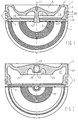
- Fig. 1 shows an upper part 1 of a piston whose lower part is not shown in the figure. Is marked in Fig. 1 half the bottom view of the upper part 1, which shows an inner, radially aligned contact surfaces 2 and an outer, radially aligned contact surface 3, wherein the upper part 1 rests on the contact surfaces 2 and 3 on the lower part of the piston 1.
- the upper part 1 is made of steel.
- the lower part can be made of steel, aluminum or cast iron with nodular graphite.
- the upper part 1 has a combustion bowl 5 molded into its piston head 4.
- the piston-bottom-side region of the radial outer side of the upper part 1 is designed as a land land 6, which is followed in a direction away from the piston crown by a ring part 7 with three annular grooves 8, 9 and 10.
- the piston bottom facing away from the underside of the upper part 1 has coaxial with the piston axis 11, a threaded bolt 12 through which the upper part 1 is bolted to the lower part of the piston.
- a radially inner, annular recesses 13 and a radially outer, annular recess 14 are arranged on the underside of the upper part 1, which together with piston bottom side recesses in the lower part form closed ring channels for the passage of cooling oil.
- the inner recess 13 is bounded radially inwardly by the threaded bolt 12 and radially outwardly by an annular rib 15 arranged between the recesses 13 and 14.
- the outer recess 14 is radially inwardly of the annular rib 15 and radially outward from one to the piston crown 4 molded annular wall 25 limited, on the radial outer side of the top land 6 and the ring section 7 are arranged.
- the piston bottom facing away from the bottom of the annular rib 15 carries the inner contact surface 2.
- a circumferential recess 16 is radially inwardly formed, which has the outer bearing surface 3.
- a profile with a groove shape which likewise conforms to the standard DIN EN ISO 1302, and which is described in more detail with the graphic symbols X (crossed grooves) or the graphic symbol R (grooves in the form of radially arranged sheets).
- Fig. 2 shows the upper part 17 of a built piston, which is different from the in Fig. 1 illustrated upper part 1 differs in that it has on the bottom side facing away from the bottom coaxial with the piston axis 24 blind hole 18 having an internal thread 19 into which a screw for assembling the upper part 17 with a in Fig. 2 not shown lower part can be screwed.
- Another difference between the two tops 1 and 17 is that the top 17 only the piston bottom facing away, radially aligned inner contact surface 20 of the annular rib 21 which is disposed between an outer recess 22 and an inner recess 23 on the underside of the upper part 17 , has a profile in the form of concentric grooves, as shown in the lower half view of the upper part 17 shows. In the Fig. 2 shown profiling of only one of the two bearing surfaces is sufficient at lower ignition pressures less highly loaded piston.
Landscapes
- Engineering & Computer Science (AREA)
- General Engineering & Computer Science (AREA)
- Chemical & Material Sciences (AREA)
- Combustion & Propulsion (AREA)
- Mechanical Engineering (AREA)
- Pistons, Piston Rings, And Cylinders (AREA)
Description
Die Erfindung betrifft ein Oberteil eines gebauten Kolbens nach dem Oberbegriff des Anspruches 1.The invention relates to an upper part of a built-up piston according to the preamble of claim 1.
Aus der
Diesen Nachteil des Standes der Technik zu vermeiden, ist Aufgabe der Erfindung. Gelöst wird diese Aufgabe mit den im Kennzeichen des Hauptanspruches stehenden Merkmalen, wobei es ein einfach zu realisierender und damit preisgünstiger Weg ist, zur Vermeidung des Verschleißes der Kontaktflächen des Oberteils und Unterteils eines gebauten Kolbens die Kontaktfläche des Oberteils mit einem rillenförmigen Profil zu versehen. Ein Kolbenoberteil mit auf seiner inneren Kontaktfläche konzentrisch angeordneten Nuten mit einer Tiefe von 10 bis 500 µm ist aus
- Fig. 1
- ein Oberteil eines Kolbens, das einen mittig angeordneten Gewindebolzen zum Verschrauben des Oberteiles mit dem Unterteil des Kolbens aufweist, und dessen zur Hälfte dargestellte Unteransicht, und
- Fig. 2
- ein Oberteil eines Kolbens, das eine mittig angeordnete Sacklochbohrung mit Innengewinde zur Aufnahme einer Schraube aufweist, womit das Oberteil mit dem Unterteil des Kolbens verschraubt wird, und dessen zur Hälfte dargestellte Unteransicht.
- Fig. 1
- an upper part of a piston having a centrally located threaded bolt for screwing the upper part to the lower part of the piston, and its half-view bottom view, and
- Fig. 2
- an upper part of a piston having a centrally located blind hole bore with internal thread for receiving a screw, whereby the upper part is screwed to the lower part of the piston, and its half-view bottom view.
Das Oberteil 1 weist eine in seinen Kolbenboden 4 eingeformte Verbrennungsmulde 5 auf. Der kolbenbodenseitige Bereich der radialen Außenseite des Oberteils 1 ist als Feuersteg 6 ausgebildet, dem sich in kolbenbodenabgewandte Richtung eine Ringpartie 7 mit drei Ringnuten 8, 9 und 10 anschließt.The upper part 1 has a
Die kolbenbodenabgewandte Unterseite des Oberteils 1 weist koaxial zur Kolbenachse 11 einen Gewindebolzen 12 auf, über den das Oberteil 1 mit dem Unterteil des Kolbens verschraubt ist. Konzentrisch zur Kolbenachse 11 und konzentrisch zueinander sind auf der Unterseite des Oberteils 1 eine radial innere, ringförmige Ausnehmungen 13 und eine radial äußere, ringförmige Ausnehmung 14 angeordnet, die gemeinsam mit kolbenbodenseitigen Ausnehmungen im Unterteil geschlossene Ringkanäle zum Durchleiten von Kühlöl bilden. Begrenzt ist die innere Ausnehmung 13 radial innen von dem Gewindebolzen 12 und radial außen von einer zwischen den Ausnehmungen 13 und 14 angeordneten Ringrippe 15. Die äußere Ausnehmung 14 ist radial innen von der Ringrippe 15 und radial außen von einer an den Kolbenboden 4 angeformten Ringwand 25 begrenzt, auf dessen radialer Außenseite der Feuersteg 6 und die Ringpartie 7 angeordnet sind.The piston bottom facing away from the underside of the upper part 1 has coaxial with the piston axis 11, a threaded
Die kolbenbodenabgewandte Unterseite der Ringrippe 15 trägt die innere Kontaktfläche 2. In dem kolbenbodenabgewandten Endbereich der Ringwand 25 ist radial innen eine umlaufende Ausnehmung 16 eingeformt, die die äußere Auflagefläche 3 aufweist.The piston bottom facing away from the bottom of the
Wegen der in neueren Motoren gestiegenen Zünddrücke nehmen in den darin verwendeten gebauten Kolben, die aus einem Oberteil und einem Unterteil bestehen, wobei das Oberteil mit dem Unterteil verschraubt ist, auch die Kontaktpressung und die Relativbewegungen zwischen den in Kontakt miteinander stehenden Flächen des Oberteils und des Unterteils zu. Die Folgen sind ein erhöhter Reibverschleiß (fretting) der Kontaktflächen als Folge von Materialverschweißungen (microwelding) mit darauf zurückzuführenden, partiellen Materialauslösungen.Because of the increased ignition pressures in newer engines, in the built-up pistons used therein, which consist of a top and a bottom, the top being bolted to the bottom, also the contact pressure and relative movements between the contacting surfaces of the top and Lower parts too. The consequences are increased fretting of the contact surfaces as a result of material welding (microwelding) with partial material firings due to it.
In Versuchen hat sich gezeigt, dass hiergegen Abhilfe geschaffen werden kann, wenn die Kontaktflächen 2 und 3 des Oberteiles 1 des Kolbens aufgeraut werden, wobei sich ein rillenförmiges Profil als besonders wirkungsvoll bei der Vermeidung des Verschleißes der Kontaktflächen 2, 3 erwiesen hat, das eine Rauheit zwischen Rz 10 und Rz 25, d.h., eine Profilstruktur aufweist, bei der die mittlere Abweichung des Profils von einer O-Achse in positive und negative Richtung 10 µm bis 25 µm beträgt. Hierbei kann das Profil der Kontaktflächen 2 und 3 die Form konzentrischer Rillen (siehe Norm DIN EN ISO 1302, bezeichnet mit dem graphischen Symbol C) mit einem Rillenabstand von 300 bis 1200 µm aufweisen, wie es in
Möglich ist auch ein Profil mit einer Rillenform, die sich ebenfalls an die Norm DIN EN ISO 1302 anlehnt, und die mit dem graphischen Symbolen X (gekreuzte Rillen) oder dem graphischen Symbol R (Rillen in Form radial angeordneter Blätter) näher bezeichnet wird.Also possible is a profile with a groove shape, which likewise conforms to the standard DIN EN ISO 1302, and which is described in more detail with the graphic symbols X (crossed grooves) or the graphic symbol R (grooves in the form of radially arranged sheets).
Zur Vermeidung des Verschleißes der Kontaktflächen von Ober- und Unterteil eines gebauten Kolbens ist es auch möglich, eine oder mehrere kolbenbodenseitige, radial ausgerichtete Kontaktflächen des Kolbenunterteils mit der rillenförmigen Profilierung zu versehen, die die oben genannten Bemaßungen, d.h., Rauheit und Rillenabstand, und die oben angegebenen DIN-Formen aufweist.To avoid the wear of the contact surfaces of the upper and lower part of a built piston, it is also possible to provide one or more piston bottom side, radially aligned contact surfaces of the piston lower part with the groove-shaped profiling, the above-mentioned dimensions, ie, roughness and groove spacing, and Having indicated above DIN-forms.
- 11
- Oberteil eines gebauten KolbensTop part of a built-up piston
- 22
- innere Kontaktflächeinner contact surface
- 33
- äußere Kontaktflächeouter contact surface
- 44
- Kolbenbodenpiston crown
- 55
- Verbrennungsmuldecombustion bowl
- 66
- Feuerstegtop land
- 77
- Ringpartiering belt
- 8, 9, 108, 9, 10
- Ringnutring groove
- 1111
- Kolbenachsepiston axis
- 1212
- Gewindebolzenthreaded bolt
- 1313
- innere Ausnehmunginner recess
- 1414
- äußere Ausnehmungouter recess
- 1515
- Ringrippeannular rib
- 1616
- Ausnehmungrecess
- 1717
- Oberteil eines gebauten KolbensTop part of a built-up piston
- 1818
- SacklochbohrungBlind hole
- 1919
- Innengewindeinner thread
- 2020
- innere Kontaktflächeinner contact surface
- 2121
- Ringrippeannular rib
- 2222
- äußere Ausnehmungouter recess
- 2323
- innere Ausnehmunginner recess
- 2424
- Kolbenachsepiston axis
- 2525
- Ringwandring wall
Claims (1)
- Upper part (1, 17) of a composite piston,- with a piston crown (4),- with a ring wall (25) which is formed onto the piston crown (4) in the direction facing away from the piston crown, on the radial outer surface of which ring wall a ring belt (7) is disposed,- with a ring-shaped outer recess (14, 22) formed into the underside facing away from the piston crown, the recess being delimited radially on the outside by the ring wall (25), and radially on the inside by a ring rib (15, 21) formed onto the underside of the upper part (1, 17),- with an inner contact surface (2, 20) disposed on the underside of the ring rib (15, 21) and oriented radially, and- with an outer contact surface (3) disposed on the underside of the ring wall (25) and oriented radially,- wherein the inner contact surface (2, 20) has a groove-shaped profile having an average roughness depth between Rz 10 and Rz 30,characterized in that- the profile of the inner contact surface (2, 20) has the shape of concentrically disposed grooves having a groove spacing between 300 µm and 1200 µm,- in addition to the inner contact surface (2, 20), the outer contact surface (3) also has a groove-shaped profile having an average roughness depth between Rz 10 and Rz 30, wherein the profile has the shape of concentrically disposed grooves having a groove spacing between 300 µm and 1200 µm.
Applications Claiming Priority (2)
| Application Number | Priority Date | Filing Date | Title |
|---|---|---|---|
| DE102006015587A DE102006015587A1 (en) | 2006-04-04 | 2006-04-04 | Top part of a built-up piston |
| PCT/DE2007/000536 WO2007115528A1 (en) | 2006-04-04 | 2007-03-23 | Upper part of an assembled piston |
Publications (2)
| Publication Number | Publication Date |
|---|---|
| EP2002104A1 EP2002104A1 (en) | 2008-12-17 |
| EP2002104B1 true EP2002104B1 (en) | 2017-05-10 |
Family
ID=38326771
Family Applications (1)
| Application Number | Title | Priority Date | Filing Date |
|---|---|---|---|
| EP07722095.2A Active EP2002104B1 (en) | 2006-04-04 | 2007-03-23 | Upper part of an assembled piston |
Country Status (7)
| Country | Link |
|---|---|
| US (1) | US8079299B2 (en) |
| EP (1) | EP2002104B1 (en) |
| JP (1) | JP5091227B2 (en) |
| KR (1) | KR101443396B1 (en) |
| CN (1) | CN101415929B (en) |
| DE (1) | DE102006015587A1 (en) |
| WO (1) | WO2007115528A1 (en) |
Families Citing this family (1)
| Publication number | Priority date | Publication date | Assignee | Title |
|---|---|---|---|---|
| DE102006055251A1 (en) | 2006-11-23 | 2008-05-29 | Mahle International Gmbh | Two-piece piston for an internal combustion engine |
Family Cites Families (11)
| Publication number | Priority date | Publication date | Assignee | Title |
|---|---|---|---|---|
| CH406736A (en) * | 1962-09-11 | 1966-01-31 | Mirrlees National Limited | Pistons for internal combustion engines |
| US3465651A (en) * | 1968-02-13 | 1969-09-09 | Alco Products Inc | Composite pistons |
| DE2832970A1 (en) * | 1978-07-27 | 1980-02-07 | Schmidt Gmbh Karl | BUILT LIQUID-COOLED PISTON FOR INTERNAL COMBUSTION ENGINES |
| DE2936630C2 (en) * | 1979-09-11 | 1985-05-09 | Mtu Motoren- Und Turbinen-Union Friedrichshafen Gmbh, 7990 Friedrichshafen | Pistons for an internal combustion engine |
| DE3633134A1 (en) * | 1986-09-30 | 1988-04-07 | Man B & W Diesel Gmbh | Built piston for internal combustion engines |
| DE3926791A1 (en) * | 1989-08-14 | 1991-02-21 | Kriegler Franz | Piston for IC engine - has crown attached to body by fasteners which minimise heat conduction |
| DE4129746C2 (en) * | 1991-09-06 | 1994-04-14 | Man B & W Diesel Ag | Built pistons for reciprocating machines |
| JPH08210180A (en) * | 1995-02-03 | 1996-08-20 | Mitsubishi Heavy Ind Ltd | Piston |
| DK176124B1 (en) * | 1999-04-07 | 2006-09-11 | Man B & W Diesel As | Piston and piston rod for an internal combustion engine |
| FI113683B (en) * | 2001-06-04 | 2004-05-31 | Waertsilae Finland Oy | Piston unit at an internal combustion engine |
| DE102004027974A1 (en) * | 2004-06-08 | 2005-12-29 | Mahle Gmbh | A built piston and method of preventing damage in contact surfaces of the top and bottom of the piston |
-
2006
- 2006-04-04 DE DE102006015587A patent/DE102006015587A1/en not_active Withdrawn
-
2007
- 2007-03-23 EP EP07722095.2A patent/EP2002104B1/en active Active
- 2007-03-23 CN CN2007800124248A patent/CN101415929B/en active Active
- 2007-03-23 WO PCT/DE2007/000536 patent/WO2007115528A1/en not_active Ceased
- 2007-03-23 JP JP2009503402A patent/JP5091227B2/en not_active Expired - Fee Related
- 2007-03-23 US US12/225,900 patent/US8079299B2/en active Active
- 2007-03-23 KR KR1020087024114A patent/KR101443396B1/en active Active
Also Published As
| Publication number | Publication date |
|---|---|
| JP5091227B2 (en) | 2012-12-05 |
| US20090173224A1 (en) | 2009-07-09 |
| KR20090004901A (en) | 2009-01-12 |
| CN101415929A (en) | 2009-04-22 |
| US8079299B2 (en) | 2011-12-20 |
| CN101415929B (en) | 2011-12-28 |
| KR101443396B1 (en) | 2014-09-24 |
| DE102006015587A1 (en) | 2007-10-11 |
| WO2007115528A1 (en) | 2007-10-18 |
| JP2009532612A (en) | 2009-09-10 |
| EP2002104A1 (en) | 2008-12-17 |
Similar Documents
| Publication | Publication Date | Title |
|---|---|---|
| DE3604661C2 (en) | ||
| EP1828587B1 (en) | Multipart, cooled piston for a combustion engine | |
| EP2129899B1 (en) | Piston for an internal combustion engine | |
| DE102008056203A1 (en) | Multi-part piston for an internal combustion engine and method for its production | |
| EP1546536B1 (en) | Single-part cooling channel piston for an internal combustion engine | |
| EP1583897B1 (en) | Method for the introduction of shaker drillings in the cooling channel of a one-piece piston | |
| WO2010051878A1 (en) | Internal combustion engine piston with cooling channel said piston comprising a sealing element sealing the cooling channel | |
| EP0714485A1 (en) | Light metal piston for highly stressed internal combustion engines | |
| DD286026A5 (en) | CYLINDER HEAD FIRE SEAL FOR A PISTON ENGINE | |
| EP3334918A1 (en) | Piston for an internal combustion engine | |
| WO2007025622A1 (en) | Piston comprising a circumferential radial recess located below an annular groove | |
| DE2709359A1 (en) | PISTON RING FOR PISTON INTERNAL ENGINEERING MACHINES | |
| EP1819922A1 (en) | Two-part piston for a combustion engine | |
| DE10340291A1 (en) | Piston for an internal combustion engine | |
| DE102015006354A1 (en) | Piston for an internal combustion engine | |
| WO2013004218A1 (en) | Piston for an internal combustion engine | |
| EP2002104B1 (en) | Upper part of an assembled piston | |
| DE102005041001A1 (en) | Lightweight piston for internal combustion engine has arched zone inside piston at transition from gudgeon pin boring in direction of shaft wall section | |
| DE10321034B3 (en) | Piston-type internal combustion engine, e.g. for vehicle, has insert fitted without play between cylinder liner and cylinder head | |
| DE102017205152A1 (en) | PISTON WITH GROOVED VARIABLE DEEP | |
| DE3538978C1 (en) | Piston-ring arrangement for trunk pistons | |
| EP2923122B1 (en) | Piston for an internal combustion engine | |
| EP3850249B1 (en) | Piston ring and piston with internal groove sealing | |
| DE102017215834A1 (en) | piston | |
| DE102009018981A1 (en) | Piston for internal combustion engine, has hub for bearing gudgeon pin and piston skirt and spaced from piston skirt by recesses of piston skirt, where piston skirt is formed by two circular cylinder segments |
Legal Events
| Date | Code | Title | Description |
|---|---|---|---|
| PUAI | Public reference made under article 153(3) epc to a published international application that has entered the european phase |
Free format text: ORIGINAL CODE: 0009012 |
|
| 17P | Request for examination filed |
Effective date: 20080926 |
|
| AK | Designated contracting states |
Kind code of ref document: A1 Designated state(s): DE ES FI FR GB IT |
|
| DAX | Request for extension of the european patent (deleted) | ||
| RBV | Designated contracting states (corrected) |
Designated state(s): DE ES FI FR GB IT |
|
| 17Q | First examination report despatched |
Effective date: 20100614 |
|
| GRAP | Despatch of communication of intention to grant a patent |
Free format text: ORIGINAL CODE: EPIDOSNIGR1 |
|
| INTG | Intention to grant announced |
Effective date: 20161222 |
|
| GRAS | Grant fee paid |
Free format text: ORIGINAL CODE: EPIDOSNIGR3 |
|
| GRAA | (expected) grant |
Free format text: ORIGINAL CODE: 0009210 |
|
| AK | Designated contracting states |
Kind code of ref document: B1 Designated state(s): DE ES FI FR GB IT |
|
| REG | Reference to a national code |
Ref country code: GB Ref legal event code: FG4D Free format text: NOT ENGLISH |
|
| REG | Reference to a national code |
Ref country code: DE Ref legal event code: R096 Ref document number: 502007015631 Country of ref document: DE |
|
| PG25 | Lapsed in a contracting state [announced via postgrant information from national office to epo] |
Ref country code: ES Free format text: LAPSE BECAUSE OF FAILURE TO SUBMIT A TRANSLATION OF THE DESCRIPTION OR TO PAY THE FEE WITHIN THE PRESCRIBED TIME-LIMIT Effective date: 20170510 |
|
| REG | Reference to a national code |
Ref country code: DE Ref legal event code: R097 Ref document number: 502007015631 Country of ref document: DE |
|
| PG25 | Lapsed in a contracting state [announced via postgrant information from national office to epo] |
Ref country code: IT Free format text: LAPSE BECAUSE OF FAILURE TO SUBMIT A TRANSLATION OF THE DESCRIPTION OR TO PAY THE FEE WITHIN THE PRESCRIBED TIME-LIMIT Effective date: 20170510 |
|
| PLBE | No opposition filed within time limit |
Free format text: ORIGINAL CODE: 0009261 |
|
| STAA | Information on the status of an ep patent application or granted ep patent |
Free format text: STATUS: NO OPPOSITION FILED WITHIN TIME LIMIT |
|
| 26N | No opposition filed |
Effective date: 20180213 |
|
| GBPC | Gb: european patent ceased through non-payment of renewal fee |
Effective date: 20180323 |
|
| PG25 | Lapsed in a contracting state [announced via postgrant information from national office to epo] |
Ref country code: GB Free format text: LAPSE BECAUSE OF NON-PAYMENT OF DUE FEES Effective date: 20180323 |
|
| PG25 | Lapsed in a contracting state [announced via postgrant information from national office to epo] |
Ref country code: FR Free format text: LAPSE BECAUSE OF NON-PAYMENT OF DUE FEES Effective date: 20180331 |
|
| PGFP | Annual fee paid to national office [announced via postgrant information from national office to epo] |
Ref country code: FI Payment date: 20230323 Year of fee payment: 17 |
|
| P01 | Opt-out of the competence of the unified patent court (upc) registered |
Effective date: 20240527 |
|
| PG25 | Lapsed in a contracting state [announced via postgrant information from national office to epo] |
Ref country code: FI Free format text: LAPSE BECAUSE OF NON-PAYMENT OF DUE FEES Effective date: 20240323 |
|
| PG25 | Lapsed in a contracting state [announced via postgrant information from national office to epo] |
Ref country code: FI Free format text: LAPSE BECAUSE OF NON-PAYMENT OF DUE FEES Effective date: 20240323 |
|
| PGFP | Annual fee paid to national office [announced via postgrant information from national office to epo] |
Ref country code: DE Payment date: 20250319 Year of fee payment: 19 |