EP2001762B1 - Safety seal for closing receptacles of various closing diameters - Google Patents
Safety seal for closing receptacles of various closing diameters Download PDFInfo
- Publication number
- EP2001762B1 EP2001762B1 EP06804867A EP06804867A EP2001762B1 EP 2001762 B1 EP2001762 B1 EP 2001762B1 EP 06804867 A EP06804867 A EP 06804867A EP 06804867 A EP06804867 A EP 06804867A EP 2001762 B1 EP2001762 B1 EP 2001762B1
- Authority
- EP
- European Patent Office
- Prior art keywords
- combination lock
- safety seal
- locking ring
- code
- receptacles
- Prior art date
- Legal status (The legal status is an assumption and is not a legal conclusion. Google has not performed a legal analysis and makes no representation as to the accuracy of the status listed.)
- Not-in-force
Links
Images


Classifications
-
- B—PERFORMING OPERATIONS; TRANSPORTING
- B65—CONVEYING; PACKING; STORING; HANDLING THIN OR FILAMENTARY MATERIAL
- B65D—CONTAINERS FOR STORAGE OR TRANSPORT OF ARTICLES OR MATERIALS, e.g. BAGS, BARRELS, BOTTLES, BOXES, CANS, CARTONS, CRATES, DRUMS, JARS, TANKS, HOPPERS, FORWARDING CONTAINERS; ACCESSORIES, CLOSURES, OR FITTINGS THEREFOR; PACKAGING ELEMENTS; PACKAGES
- B65D55/00—Accessories for container closures not otherwise provided for
- B65D55/02—Locking devices; Means for discouraging or indicating unauthorised opening or removal of closure
- B65D55/14—Applications of locks, e.g. of permutation or key-controlled locks
- B65D55/145—Applications of locks, e.g. of permutation or key-controlled locks of permutation locks
-
- B—PERFORMING OPERATIONS; TRANSPORTING
- B65—CONVEYING; PACKING; STORING; HANDLING THIN OR FILAMENTARY MATERIAL
- B65D—CONTAINERS FOR STORAGE OR TRANSPORT OF ARTICLES OR MATERIALS, e.g. BAGS, BARRELS, BOTTLES, BOXES, CANS, CARTONS, CRATES, DRUMS, JARS, TANKS, HOPPERS, FORWARDING CONTAINERS; ACCESSORIES, CLOSURES, OR FITTINGS THEREFOR; PACKAGING ELEMENTS; PACKAGES
- B65D2255/00—Locking devices
Definitions
- the present invention deals with a safety seal according to the preamble of the independent claim 1.
- the safety seal has to be applied on greatly varying receptacles, it must encompass in the opened state the largest possible diameter of the original sealing system, but also clamp onto the opening neck of the smallest possible closure diameter. The closer shall therefore provide a large closing stroke.
- the safety seal of document WO 03/024829 uses a rotating support plate screwed in an inner side of a concave portion, so as to move vertically.
- Such sealing system due to its technical structure, encompasses a relatively limited range of catch diameters of bottles, so it is intended to lock an airtight container storing expensive samples or alcoholic liquors for private use.
- Fig. 2 thereby shows that the seal is to be used for bottles which get screwed to the safety seal.
- the locking device is closely supported through not only the rotating support plate of the upper cover supported by the cap of the storage container but also the diaphraqm plate of the lower cover, so a non-allowed person cannot open the storage container.
- This prior art structure also strongly limits the type of bottles for which the prior art safety seal is suitable.
- the firm Kwiktop offers reusable bottle closing means for bottles with beverages.
- such means close only PET-bottles of a very narrow range of diameters- Therefore, such reusable bottle closing means are not usable for bottles with a drinking device as used by sportsmen.
- the safety seal according to the preamble of the independent claim 1 is provided with the means as defined in the characterizinq part of independent claim 1, and preferred embodiments are defined in the dependent claims thereto.
- Claim 4 defines the use of such a safety seal according to one or more of claims 1 to 3.
- the safety seal consists of a seal body 1 which contains the combination lock 2 and a disk 3 with spiral slots 4. Furthermore it consists of a locking ring 5 that comprises a disk 3 with radial guide grooves 6 and clamping wings 7 running in them. Onto the locking ring 5 are holes 19, in which a pusher 10 of the permutation or combination lock is pressed inside.
- the combination lock 2 consists of at least three handwheels 9, a pusher 10 and a compression spring 11.
- the pusher 10 has a wedge 14 each lying on an axis. An additional surface on the pusher 10 prevents its rotation and exactly defines its position in the combination lock 2.
- the pusher 10 When the handwheels 9 are in the handwheels opened position 9a, the pusher 10 can be moved up and down and by this the safety seal can be opened or closed. When the handwheel 9 is not in this position, but in the handwheels closed position 9b, then the pusher 10 sits tightly in one of the recesses 13, so that the seal body 1 and the locking ring 5 cannot be rotated against each other and thus the clamping wing 7 be blocked.
- the pusher 10 can only be moved if, after inputting the correct code combination, all handwheels 9 arc in the correct position.
- the clamping wing 7 in the safety seal retracts. The safety seal can then be pulled over the original sealing system and the original cover is accessible.
- the safety seal is carrried out with an electronic combination lock ( Fig. 5 ).
- the linear actuator 15 prevents a relative rotation of the seal body 1 and the locking ring 5.
- the linear actuator 15 is fitted into the seal body 1 and its anchor viz. armature 16 engages in a hole 19 of the locking ring 5.
- a code with at least 1 up to a maximum of 16 digits, preferably 2-6 digits, can be programmed.
- the code is inputted by using the rotatable code ring 20.
- the direction of the rotation and the rotation angle of the rotatable code ring 20 are sensed and evaluated.
- a preferred coding starts with a whole turn of the rotatable code ring 20.
- Each new code digit is then initiated by a counter-rotation and a rotation angle preferentially measured in units of 36° in order to code the digit. Is the code input correct, the linear actuator 15 is actuated and the safety seal can be opened and removed.
- the range of catch diameters which is applicable is between a minimum of 5 mm and a maximum of 100 mm with a preferred range of 20 - 45 mm for bottles and a preferred range of 6 - 25 mm for tubes and a preferred range of 30 - 100 mm for cans. It is also possible to safely lock bottles with additional drinking means.
- the safety seal is rapidly mountable, can rapidly be removed and is designed to be constantly closed and reopened.
Landscapes
- Engineering & Computer Science (AREA)
- Mechanical Engineering (AREA)
- Closures For Containers (AREA)
Abstract
Description
- The present invention deals with a safety seal according to the preamble of the
independent claim 1. - Many top sportsmen fear not self-caused doping. To avoid the, they need a simple and reusable safety seal for bottles of beverages of all kinds, which is simple to mount and to close. Also in the case of application of technical means for tampering with should the safety seal not be opened nor be closed going unnoticed. A safety seal on receptacles with dangerous chemical substances and cleaning agents should prevent access of unauthorized pensions to poisonous and dangerous substances. To these means also counts the known child safety lock for dangerous substances, which are however not provided with a key and which therefore cannot offer 100 percent protection. There are also not liquid substances like pills, tablets, powders, pastes and creams etc., which are held in receptacles with very different closing diameters, and there is a need to secure them against unauthorized opening.
- Tf the safety seal has to be applied on greatly varying receptacles, it must encompass in the opened state the largest possible diameter of the original sealing system, but also clamp onto the opening neck of the smallest possible closure diameter. The closer shall therefore provide a large closing stroke.
- Today, the market offers safety seals for champagne and other wine bottles, e.g. of the EGO type with a permutation or combination lock of Leopold. Such sealing systems are not designed to close bottles of varying diameters of collar and of original closure means. Moreover, they can only be used if the original closing means are removed, and such a system is just not applicable for bottles with is drinking device as used by sportsmen.
- To perform scaling, the safety seal of document
WO 03/024829 Fig. 2 thereby shows that the seal is to be used for bottles which get screwed to the safety seal. The locking device is closely supported through not only the rotating support plate of the upper cover supported by the cap of the storage container but also the diaphraqm plate of the lower cover, so a non-allowed person cannot open the storage container. This prior art structure also strongly limits the type of bottles for which the prior art safety seal is suitable. - The firm Kwiktop offers reusable bottle closing means for bottles with beverages. However, such means close only PET-bottles of a very narrow range of diameters- Therefore, such reusable bottle closing means are not usable for bottles with a drinking device as used by sportsmen.
- In the European Patent
EP-B1-1 121 300 and in further related patents there is described a safety bottle cap which possesses an indentment which can be shifted inwardly and which for its opening needs a mechanical key means which lifts the indentment. This solution is also limited to a small closing stroke and is applied to a security means against theft and to means for electronic identification of bottles. And for many applications, it is not desirably to use a mechanical key in any form. - In order to overcome all these drawbacks of the prior art, the safety seal according to the preamble of the
independent claim 1 is provided with the means as defined in the characterizinq part ofindependent claim 1, and preferred embodiments are defined in the dependent claims thereto. -
Claim 4 defines the use of such a safety seal according to one or more ofclaims 1 to 3. - The invention will now be described in a more specific way as shown in a non-limiting way by the drawings. They show:
-
Fig. 1 a safety seal for a bottle -
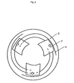
Fig. 2 a disk with spiral slots -
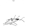
Fig. 3 a disk with radial guide grooves and clamping wings -
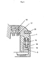
Fig. 4 a cut through a mechanical permutation or combination lock for illustrative purpose only -
Fig. 5 a cut through an electronic permutation or combination lock according to the invention - The safety seal consists of a
seal body 1 which contains thecombination lock 2 and adisk 3 withspiral slots 4. Furthermore it consists of alocking ring 5 that comprises adisk 3 withradial guide grooves 6 and clampingwings 7 running in them. Onto thelocking ring 5 areholes 19, in which apusher 10 of the permutation or combination lock is pressed inside. - With a rotation movement of the
locking ring 5 against theseal body 1, theclamping wings 7 are moved due to the action of thespiral slots 4 along theradial guide grooves 6 in the desired direction away from the bottle top collar or onto the bottle top collar. Through the pitch of the spiral the necessary stroke can be dcmultiplied. By this, the rotation movement of the safety seal and the engaging of thepusher 10 in thelocking ring 5 can be adjusted. - The
seal body 1 and thelocking ring 5 can only be rotated against each other, if the correct code combination is entered in thecombination lock 2. In case of a mechanical combination lock which, however, does not form part of the present invention, thecombination lock 2 consists of at least three handwheels 9, apusher 10 and acompression spring 11. For each handwheel 9 thepusher 10 has awedge 14 each lying on an axis. An additional surface on thepusher 10 prevents its rotation and exactly defines its position in thecombination lock 2. - When the handwheels 9 are in the handwheels opened
position 9a, thepusher 10 can be moved up and down and by this the safety seal can be opened or closed. When the handwheel 9 is not in this position, but in the handwheels closedposition 9b, then thepusher 10 sits tightly in one of therecesses 13, so that theseal body 1 and thelocking ring 5 cannot be rotated against each other and thus the clampingwing 7 be blocked. - The
pusher 10 can only be moved if, after inputting the correct code combination, all handwheels 9 arc in the correct position. By rotation in the opening direction, theclamping wing 7 in the safety seal retracts. The safety seal can then be pulled over the original sealing system and the original cover is accessible. - According to the presnt invention the safety seal is carrried out with an electronic combination lock (
Fig. 5 ). The anchor viz.armature 16 of alinear actuator 15, e.g. a lifting magnet, takes the function of thepusher 10, an additionalrotatable code ring 20 on theseal body 1 is used for code inputting, and amicroelectronics control 17, which is fed by abattery 18 replaceable from the outside, checks the code input and triggers thelinear actuator 15. Thelinear actuator 15 prevents a relative rotation of theseal body 1 and thelocking ring 5. Thelinear actuator 15 is fitted into theseal body 1 and its anchor viz.armature 16 engages in ahole 19 of thelocking ring 5. When the anchor viz.armature 16 is driven out, theseal body 1 and thelocking ring 5 cannot any longer be rotated against each other. - It the
combination lock 2 is open, a code with at least 1 up to a maximum of 16 digits, preferably 2-6 digits, can be programmed. The code is inputted by using therotatable code ring 20. In functional analogy with a computer mouse, the direction of the rotation and the rotation angle of therotatable code ring 20 are sensed and evaluated. To start inputting, a preferred coding starts with a whole turn of therotatable code ring 20. Each new code digit is then initiated by a counter-rotation and a rotation angle preferentially measured in units of 36° in order to code the digit. Is the code input correct, thelinear actuator 15 is actuated and the safety seal can be opened and removed. - By this novel and inventive safety seal it is now possible to safely lock receptacles with strongly varying catch diameters and also such receptacles with large closing strokes. Tn the applications intended, the range of catch diameters which is applicable is between a minimum of 5 mm and a maximum of 100 mm with a preferred range of 20 - 45 mm for bottles and a preferred range of 6 - 25 mm for tubes and a preferred range of 30 - 100 mm for cans. It is also possible to safely lock bottles with additional drinking means.
- The safety seal is rapidly mountable, can rapidly be removed and is designed to be constantly closed and reopened.
Claims (4)
- Safety seal for closing receptacles with a tapered opening neck of various catch diameters, which are attached over an original sealing system for protecting against unauthorized access to the substances kept therein, whose seal body (1) possesses a sufficiently large cavity to receive the original sealing system, which furthermore possesses a clamping mechanism with a plurality of organs acting upon the tapered opening neck and is provided with a combination lock (2) with adjustable code, which lock blocks a locking ring (5) through a pusher (10) and releases the locking ring (5) for manipulation only witch the correctly inserted code, characterized in that the clasping mechanism (1-14) possesses, as said plurality of organs, at least three clamping wings (7), which are radially movable, inwardly to close viz. outwardly to open, by manual rotation of a locking ring (5) against the seal body (1), to such an extent that they encompass receptacles having catch diameters between a minimum of 5 mm and a maximum of 100 mm and in that the clamping mechanism (1-14) combination lock is actuated by manually rotating a first disk (3) with at least three slots (4), which due to this turning are running inwards, which act as guidance for the clamping wings (7) against a second disk (3) having at least at three places on its periphery radial guide grooves (6), which act as counter-guidancc for the clamping wings (7), whereby either the first or the second disk (3) is situated in the seal body (1) and the respective other is situated in the locking ring (5), further in that the disk (3) in the locking ring 15) possesses holes (19) over the whole periphery, for locking the combination lock (2) by the action of the pusher (10), whereby the pusher (10) of the combination lock (2) is retracted from the hole (19) when the combination lock (2) is opened, so that by this the disks (3) can be freely rotated against each other, and is engaged in a hole (19) when the combination lock (2) is locked, so that then the disks (3) cannot any longer be moved against each other, and in that the combination lock is an electronic combination lock (2) with a rotatable code ring (20) on the seal body (1) for inputting a code with at least 1 up to a maximum of 16 digits, with a linear actuator (15), whose anchor viz. armature (16) actuates a pusher (10), with a microelectronics control (17), which is fed by a battery (18) which ist replaceable from the outsize, which microelectronics control recognize the coding, checks the coding and in the case of a correct result, actuates the linear actuator (15).
- Safety seal according to claim 1, characterized in that said number of digits is 2-6 digits.
- Safety seal according to claim 1 or 2, characterized in that said coding starts with a whole turn of the rotatable code ring (20), followed for each digit by a counter-rotation and a rotation angle preferentially measured in units of 36° in order to code the digit.
- Use of a safety seal according to one or more of claims 1 to 3 for securing receptacles with either liquid type or non-liquid type substances like creams, pastes, powders, granulates, pills and tablets, which receptacles have catch diameters with a preferred range of 20 - 45 mm for bottles and a preferred range of 6 - 25 mm for tubers and a preferred range of 30 - 100 mm for cans, whereby also bottles with additional drinking means can be safely locked and secured.
Applications Claiming Priority (2)
| Application Number | Priority Date | Filing Date | Title |
|---|---|---|---|
| CH20962005 | 2005-12-30 | ||
| PCT/CH2006/000635 WO2007076616A1 (en) | 2005-12-30 | 2006-11-13 | Safety seal for closing receptacles of various closing diameters |
Publications (2)
| Publication Number | Publication Date |
|---|---|
| EP2001762A1 EP2001762A1 (en) | 2008-12-17 |
| EP2001762B1 true EP2001762B1 (en) | 2011-12-14 |
Family
ID=37688953
Family Applications (1)
| Application Number | Title | Priority Date | Filing Date |
|---|---|---|---|
| EP06804867A Not-in-force EP2001762B1 (en) | 2005-12-30 | 2006-11-13 | Safety seal for closing receptacles of various closing diameters |
Country Status (3)
| Country | Link |
|---|---|
| EP (1) | EP2001762B1 (en) |
| AT (1) | ATE537075T1 (en) |
| WO (1) | WO2007076616A1 (en) |
Families Citing this family (2)
| Publication number | Priority date | Publication date | Assignee | Title |
|---|---|---|---|---|
| CN104948020A (en) * | 2015-07-07 | 2015-09-30 | 包国菊 | Container tank coded lock |
| CN107758104A (en) * | 2016-08-22 | 2018-03-06 | 上海圣享科技股份有限公司 | Bottle cap coded lock |
Family Cites Families (5)
| Publication number | Priority date | Publication date | Assignee | Title |
|---|---|---|---|---|
| US5515634A (en) * | 1994-05-17 | 1996-05-14 | Kong; Yu W. | Household safety lock and gun lock guard |
| US5911764A (en) * | 1997-07-28 | 1999-06-15 | Wei Kong; Yu | Bottle lock with a chuck device |
| KR100412322B1 (en) * | 2001-09-03 | 2003-12-31 | 권경우 | A Device for Locking of Airtight Case |
| US7004340B2 (en) * | 2003-07-25 | 2006-02-28 | Alpha Security Products, Inc. | Bottle security device |
| ES2245873B1 (en) * | 2004-03-23 | 2007-02-16 | Juan De Bagration De Ulloa | DEVICE TO PREVENT THE UNAUTHORIZED HANDLING OF CONTAINER PLUGS. |
-
2006
- 2006-11-13 WO PCT/CH2006/000635 patent/WO2007076616A1/en not_active Ceased
- 2006-11-13 AT AT06804867T patent/ATE537075T1/en active
- 2006-11-13 EP EP06804867A patent/EP2001762B1/en not_active Not-in-force
Also Published As
| Publication number | Publication date |
|---|---|
| EP2001762A1 (en) | 2008-12-17 |
| WO2007076616A1 (en) | 2007-07-12 |
| ATE537075T1 (en) | 2011-12-15 |
Similar Documents
| Publication | Publication Date | Title |
|---|---|---|
| US5586670A (en) | Bottle security system | |
| EP2473419B1 (en) | Lockable cap for a bottle | |
| EP3947180A1 (en) | Tethered cap and spout | |
| US20020152780A1 (en) | Shielded pushbutton lock | |
| US8100297B1 (en) | Locking container cap and dispenser for fuel | |
| US4588098A (en) | Closures for containers having tampering indicating means | |
| US6371316B1 (en) | Child resistant closure and container with guarded flip-top | |
| JP6609049B2 (en) | Improvements in / related to closures for container necks | |
| US4779747A (en) | Container having a stopper for the container | |
| US8123057B2 (en) | Security rotating closure for a multi-compartment bottle including conical seals | |
| US10099830B2 (en) | Lock it! | |
| CN108136788A (en) | Safe Refill System | |
| US5758788A (en) | Piercing container cap | |
| EP2001762A1 (en) | Safety seal for closing receptacles of various closing diameters | |
| US20060138072A1 (en) | Closure for a container | |
| US20020027119A1 (en) | Convertible child resistant closure | |
| US20050211658A1 (en) | Device for preventing unauthorized tampering of container caps | |
| WO2000069740A1 (en) | Locking helical closure system | |
| US441240A (en) | Locking-stopper for bottles | |
| US20150225149A1 (en) | Underground tank locking and sealing mechanism | |
| JP3766102B2 (en) | Perforated container cap | |
| EP2665659B1 (en) | Locking closure for an oil storage tank | |
| DE36343C (en) | Locking and securing for screw caps on vessels | |
| EP4624361A1 (en) | Closure device for container | |
| KR200330397Y1 (en) | Bottle cap |
Legal Events
| Date | Code | Title | Description |
|---|---|---|---|
| PUAI | Public reference made under article 153(3) epc to a published international application that has entered the european phase |
Free format text: ORIGINAL CODE: 0009012 |
|
| 17P | Request for examination filed |
Effective date: 20080626 |
|
| AK | Designated contracting states |
Kind code of ref document: A1 Designated state(s): AT BE BG CH CY CZ DE DK EE ES FI FR GB GR HU IE IS IT LI LT LU LV MC NL PL PT RO SE SI SK TR |
|
| 17Q | First examination report despatched |
Effective date: 20091023 |
|
| GRAP | Despatch of communication of intention to grant a patent |
Free format text: ORIGINAL CODE: EPIDOSNIGR1 |
|
| DAX | Request for extension of the european patent (deleted) | ||
| GRAS | Grant fee paid |
Free format text: ORIGINAL CODE: EPIDOSNIGR3 |
|
| GRAA | (expected) grant |
Free format text: ORIGINAL CODE: 0009210 |
|
| AK | Designated contracting states |
Kind code of ref document: B1 Designated state(s): AT BE BG CH CY CZ DE DK EE ES FI FR GB GR HU IE IS IT LI LT LU LV MC NL PL PT RO SE SI SK TR |
|
| REG | Reference to a national code |
Ref country code: GB Ref legal event code: FG4D |
|
| REG | Reference to a national code |
Ref country code: CH Ref legal event code: EP |
|
| REG | Reference to a national code |
Ref country code: IE Ref legal event code: FG4D |
|
| REG | Reference to a national code |
Ref country code: DE Ref legal event code: R096 Ref document number: 602006026424 Country of ref document: DE Effective date: 20120308 |
|
| REG | Reference to a national code |
Ref country code: NL Ref legal event code: VDEP Effective date: 20111214 |
|
| PG25 | Lapsed in a contracting state [announced via postgrant information from national office to epo] |
Ref country code: LT Free format text: LAPSE BECAUSE OF FAILURE TO SUBMIT A TRANSLATION OF THE DESCRIPTION OR TO PAY THE FEE WITHIN THE PRESCRIBED TIME-LIMIT Effective date: 20111214 |
|
| LTIE | Lt: invalidation of european patent or patent extension |
Effective date: 20111214 |
|
| PG25 | Lapsed in a contracting state [announced via postgrant information from national office to epo] |
Ref country code: GR Free format text: LAPSE BECAUSE OF FAILURE TO SUBMIT A TRANSLATION OF THE DESCRIPTION OR TO PAY THE FEE WITHIN THE PRESCRIBED TIME-LIMIT Effective date: 20120315 Ref country code: SI Free format text: LAPSE BECAUSE OF FAILURE TO SUBMIT A TRANSLATION OF THE DESCRIPTION OR TO PAY THE FEE WITHIN THE PRESCRIBED TIME-LIMIT Effective date: 20111214 Ref country code: LV Free format text: LAPSE BECAUSE OF FAILURE TO SUBMIT A TRANSLATION OF THE DESCRIPTION OR TO PAY THE FEE WITHIN THE PRESCRIBED TIME-LIMIT Effective date: 20111214 Ref country code: SE Free format text: LAPSE BECAUSE OF FAILURE TO SUBMIT A TRANSLATION OF THE DESCRIPTION OR TO PAY THE FEE WITHIN THE PRESCRIBED TIME-LIMIT Effective date: 20111214 Ref country code: NL Free format text: LAPSE BECAUSE OF FAILURE TO SUBMIT A TRANSLATION OF THE DESCRIPTION OR TO PAY THE FEE WITHIN THE PRESCRIBED TIME-LIMIT Effective date: 20111214 |
|
| PG25 | Lapsed in a contracting state [announced via postgrant information from national office to epo] |
Ref country code: CY Free format text: LAPSE BECAUSE OF FAILURE TO SUBMIT A TRANSLATION OF THE DESCRIPTION OR TO PAY THE FEE WITHIN THE PRESCRIBED TIME-LIMIT Effective date: 20111214 Ref country code: BE Free format text: LAPSE BECAUSE OF FAILURE TO SUBMIT A TRANSLATION OF THE DESCRIPTION OR TO PAY THE FEE WITHIN THE PRESCRIBED TIME-LIMIT Effective date: 20111214 |
|
| PG25 | Lapsed in a contracting state [announced via postgrant information from national office to epo] |
Ref country code: CZ Free format text: LAPSE BECAUSE OF FAILURE TO SUBMIT A TRANSLATION OF THE DESCRIPTION OR TO PAY THE FEE WITHIN THE PRESCRIBED TIME-LIMIT Effective date: 20111214 Ref country code: SK Free format text: LAPSE BECAUSE OF FAILURE TO SUBMIT A TRANSLATION OF THE DESCRIPTION OR TO PAY THE FEE WITHIN THE PRESCRIBED TIME-LIMIT Effective date: 20111214 Ref country code: EE Free format text: LAPSE BECAUSE OF FAILURE TO SUBMIT A TRANSLATION OF THE DESCRIPTION OR TO PAY THE FEE WITHIN THE PRESCRIBED TIME-LIMIT Effective date: 20111214 Ref country code: BG Free format text: LAPSE BECAUSE OF FAILURE TO SUBMIT A TRANSLATION OF THE DESCRIPTION OR TO PAY THE FEE WITHIN THE PRESCRIBED TIME-LIMIT Effective date: 20120314 Ref country code: IS Free format text: LAPSE BECAUSE OF FAILURE TO SUBMIT A TRANSLATION OF THE DESCRIPTION OR TO PAY THE FEE WITHIN THE PRESCRIBED TIME-LIMIT Effective date: 20120414 |
|
| PG25 | Lapsed in a contracting state [announced via postgrant information from national office to epo] |
Ref country code: PL Free format text: LAPSE BECAUSE OF FAILURE TO SUBMIT A TRANSLATION OF THE DESCRIPTION OR TO PAY THE FEE WITHIN THE PRESCRIBED TIME-LIMIT Effective date: 20111214 Ref country code: PT Free format text: LAPSE BECAUSE OF FAILURE TO SUBMIT A TRANSLATION OF THE DESCRIPTION OR TO PAY THE FEE WITHIN THE PRESCRIBED TIME-LIMIT Effective date: 20120416 Ref country code: RO Free format text: LAPSE BECAUSE OF FAILURE TO SUBMIT A TRANSLATION OF THE DESCRIPTION OR TO PAY THE FEE WITHIN THE PRESCRIBED TIME-LIMIT Effective date: 20111214 |
|
| REG | Reference to a national code |
Ref country code: AT Ref legal event code: MK05 Ref document number: 537075 Country of ref document: AT Kind code of ref document: T Effective date: 20111214 |
|
| RAP2 | Party data changed (patent owner data changed or rights of a patent transferred) |
Owner name: DR. BEUCHAT & PARTNER GMBH |
|
| RIN2 | Information on inventor provided after grant (corrected) |
Inventor name: LACIGA, PAUL MICHEL Inventor name: WEIERMANN, TOBIAS Inventor name: BIRCHER, FRITZ |
|
| PLBE | No opposition filed within time limit |
Free format text: ORIGINAL CODE: 0009261 |
|
| STAA | Information on the status of an ep patent application or granted ep patent |
Free format text: STATUS: NO OPPOSITION FILED WITHIN TIME LIMIT |
|
| PG25 | Lapsed in a contracting state [announced via postgrant information from national office to epo] |
Ref country code: DK Free format text: LAPSE BECAUSE OF FAILURE TO SUBMIT A TRANSLATION OF THE DESCRIPTION OR TO PAY THE FEE WITHIN THE PRESCRIBED TIME-LIMIT Effective date: 20111214 |
|
| 26N | No opposition filed |
Effective date: 20120917 |
|
| PG25 | Lapsed in a contracting state [announced via postgrant information from national office to epo] |
Ref country code: IT Free format text: LAPSE BECAUSE OF FAILURE TO SUBMIT A TRANSLATION OF THE DESCRIPTION OR TO PAY THE FEE WITHIN THE PRESCRIBED TIME-LIMIT Effective date: 20111214 |
|
| REG | Reference to a national code |
Ref country code: DE Ref legal event code: R097 Ref document number: 602006026424 Country of ref document: DE Effective date: 20120917 |
|
| PG25 | Lapsed in a contracting state [announced via postgrant information from national office to epo] |
Ref country code: AT Free format text: LAPSE BECAUSE OF FAILURE TO SUBMIT A TRANSLATION OF THE DESCRIPTION OR TO PAY THE FEE WITHIN THE PRESCRIBED TIME-LIMIT Effective date: 20111214 |
|
| PG25 | Lapsed in a contracting state [announced via postgrant information from national office to epo] |
Ref country code: ES Free format text: LAPSE BECAUSE OF FAILURE TO SUBMIT A TRANSLATION OF THE DESCRIPTION OR TO PAY THE FEE WITHIN THE PRESCRIBED TIME-LIMIT Effective date: 20120325 |
|
| PG25 | Lapsed in a contracting state [announced via postgrant information from national office to epo] |
Ref country code: FI Free format text: LAPSE BECAUSE OF FAILURE TO SUBMIT A TRANSLATION OF THE DESCRIPTION OR TO PAY THE FEE WITHIN THE PRESCRIBED TIME-LIMIT Effective date: 20111214 |
|
| GBPC | Gb: european patent ceased through non-payment of renewal fee |
Effective date: 20121113 |
|
| REG | Reference to a national code |
Ref country code: IE Ref legal event code: MM4A |
|
| REG | Reference to a national code |
Ref country code: FR Ref legal event code: ST Effective date: 20130731 |
|
| REG | Reference to a national code |
Ref country code: DE Ref legal event code: R119 Ref document number: 602006026424 Country of ref document: DE Effective date: 20130601 |
|
| PG25 | Lapsed in a contracting state [announced via postgrant information from national office to epo] |
Ref country code: IE Free format text: LAPSE BECAUSE OF NON-PAYMENT OF DUE FEES Effective date: 20121113 Ref country code: DE Free format text: LAPSE BECAUSE OF NON-PAYMENT OF DUE FEES Effective date: 20130601 |
|
| PG25 | Lapsed in a contracting state [announced via postgrant information from national office to epo] |
Ref country code: FR Free format text: LAPSE BECAUSE OF NON-PAYMENT OF DUE FEES Effective date: 20121130 Ref country code: GB Free format text: LAPSE BECAUSE OF NON-PAYMENT OF DUE FEES Effective date: 20121113 |
|
| PG25 | Lapsed in a contracting state [announced via postgrant information from national office to epo] |
Ref country code: MC Free format text: LAPSE BECAUSE OF NON-PAYMENT OF DUE FEES Effective date: 20121130 Ref country code: TR Free format text: LAPSE BECAUSE OF FAILURE TO SUBMIT A TRANSLATION OF THE DESCRIPTION OR TO PAY THE FEE WITHIN THE PRESCRIBED TIME-LIMIT Effective date: 20111214 |
|
| PG25 | Lapsed in a contracting state [announced via postgrant information from national office to epo] |
Ref country code: LU Free format text: LAPSE BECAUSE OF NON-PAYMENT OF DUE FEES Effective date: 20121113 |
|
| PG25 | Lapsed in a contracting state [announced via postgrant information from national office to epo] |
Ref country code: HU Free format text: LAPSE BECAUSE OF FAILURE TO SUBMIT A TRANSLATION OF THE DESCRIPTION OR TO PAY THE FEE WITHIN THE PRESCRIBED TIME-LIMIT Effective date: 20061113 |
|
| PGFP | Annual fee paid to national office [announced via postgrant information from national office to epo] |
Ref country code: CH Payment date: 20151014 Year of fee payment: 10 |
|
| REG | Reference to a national code |
Ref country code: CH Ref legal event code: PL |
|
| PG25 | Lapsed in a contracting state [announced via postgrant information from national office to epo] |
Ref country code: LI Free format text: LAPSE BECAUSE OF NON-PAYMENT OF DUE FEES Effective date: 20161130 Ref country code: CH Free format text: LAPSE BECAUSE OF NON-PAYMENT OF DUE FEES Effective date: 20161130 |