EP2001359B1 - Ultrasound catheter and hand-held device for manipulating a transducer on the catheter's distal end - Google Patents
Ultrasound catheter and hand-held device for manipulating a transducer on the catheter's distal end Download PDFInfo
- Publication number
- EP2001359B1 EP2001359B1 EP07797199.2A EP07797199A EP2001359B1 EP 2001359 B1 EP2001359 B1 EP 2001359B1 EP 07797199 A EP07797199 A EP 07797199A EP 2001359 B1 EP2001359 B1 EP 2001359B1
- Authority
- EP
- European Patent Office
- Prior art keywords
- steering
- catheter
- steering actuator
- hand
- actuator
- Prior art date
- Legal status (The legal status is an assumption and is not a legal conclusion. Google has not performed a legal analysis and makes no representation as to the accuracy of the status listed.)
- Active
Links
Images











Classifications
-
- A—HUMAN NECESSITIES
- A61—MEDICAL OR VETERINARY SCIENCE; HYGIENE
- A61B—DIAGNOSIS; SURGERY; IDENTIFICATION
- A61B8/00—Diagnosis using ultrasonic, sonic or infrasonic waves
- A61B8/44—Constructional features of the ultrasonic, sonic or infrasonic diagnostic device
- A61B8/4483—Constructional features of the ultrasonic, sonic or infrasonic diagnostic device characterised by features of the ultrasound transducer
- A61B8/4488—Constructional features of the ultrasonic, sonic or infrasonic diagnostic device characterised by features of the ultrasound transducer the transducer being a phased array
-
- A—HUMAN NECESSITIES
- A61—MEDICAL OR VETERINARY SCIENCE; HYGIENE
- A61B—DIAGNOSIS; SURGERY; IDENTIFICATION
- A61B17/00—Surgical instruments, devices or methods
- A61B17/22—Implements for squeezing-off ulcers or the like on inner organs of the body; Implements for scraping-out cavities of body organs, e.g. bones; for invasive removal or destruction of calculus using mechanical vibrations; for removing obstructions in blood vessels, not otherwise provided for
- A61B17/22004—Implements for squeezing-off ulcers or the like on inner organs of the body; Implements for scraping-out cavities of body organs, e.g. bones; for invasive removal or destruction of calculus using mechanical vibrations; for removing obstructions in blood vessels, not otherwise provided for using mechanical vibrations, e.g. ultrasonic shock waves
- A61B17/22012—Implements for squeezing-off ulcers or the like on inner organs of the body; Implements for scraping-out cavities of body organs, e.g. bones; for invasive removal or destruction of calculus using mechanical vibrations; for removing obstructions in blood vessels, not otherwise provided for using mechanical vibrations, e.g. ultrasonic shock waves in direct contact with, or very close to, the obstruction or concrement
- A61B17/2202—Implements for squeezing-off ulcers or the like on inner organs of the body; Implements for scraping-out cavities of body organs, e.g. bones; for invasive removal or destruction of calculus using mechanical vibrations; for removing obstructions in blood vessels, not otherwise provided for using mechanical vibrations, e.g. ultrasonic shock waves in direct contact with, or very close to, the obstruction or concrement the ultrasound transducer being inside patient's body at the distal end of the catheter
-
- A—HUMAN NECESSITIES
- A61—MEDICAL OR VETERINARY SCIENCE; HYGIENE
- A61B—DIAGNOSIS; SURGERY; IDENTIFICATION
- A61B8/00—Diagnosis using ultrasonic, sonic or infrasonic waves
- A61B8/12—Diagnosis using ultrasonic, sonic or infrasonic waves in body cavities or body tracts, e.g. by using catheters
-
- A—HUMAN NECESSITIES
- A61—MEDICAL OR VETERINARY SCIENCE; HYGIENE
- A61B—DIAGNOSIS; SURGERY; IDENTIFICATION
- A61B8/00—Diagnosis using ultrasonic, sonic or infrasonic waves
- A61B8/44—Constructional features of the ultrasonic, sonic or infrasonic diagnostic device
- A61B8/4444—Constructional features of the ultrasonic, sonic or infrasonic diagnostic device related to the probe
- A61B8/445—Details of catheter construction
-
- A—HUMAN NECESSITIES
- A61—MEDICAL OR VETERINARY SCIENCE; HYGIENE
- A61B—DIAGNOSIS; SURGERY; IDENTIFICATION
- A61B8/00—Diagnosis using ultrasonic, sonic or infrasonic waves
- A61B8/44—Constructional features of the ultrasonic, sonic or infrasonic diagnostic device
- A61B8/4444—Constructional features of the ultrasonic, sonic or infrasonic diagnostic device related to the probe
- A61B8/4461—Features of the scanning mechanism, e.g. for moving the transducer within the housing of the probe
-
- A—HUMAN NECESSITIES
- A61—MEDICAL OR VETERINARY SCIENCE; HYGIENE
- A61B—DIAGNOSIS; SURGERY; IDENTIFICATION
- A61B8/00—Diagnosis using ultrasonic, sonic or infrasonic waves
- A61B8/44—Constructional features of the ultrasonic, sonic or infrasonic diagnostic device
- A61B8/4483—Constructional features of the ultrasonic, sonic or infrasonic diagnostic device characterised by features of the ultrasound transducer
-
- A—HUMAN NECESSITIES
- A61—MEDICAL OR VETERINARY SCIENCE; HYGIENE
- A61B—DIAGNOSIS; SURGERY; IDENTIFICATION
- A61B8/00—Diagnosis using ultrasonic, sonic or infrasonic waves
- A61B8/48—Diagnostic techniques
- A61B8/483—Diagnostic techniques involving the acquisition of a 3D volume of data
-
- A—HUMAN NECESSITIES
- A61—MEDICAL OR VETERINARY SCIENCE; HYGIENE
- A61B—DIAGNOSIS; SURGERY; IDENTIFICATION
- A61B17/00—Surgical instruments, devices or methods
- A61B17/00234—Surgical instruments, devices or methods for minimally invasive surgery
- A61B2017/00292—Surgical instruments, devices or methods for minimally invasive surgery mounted on or guided by flexible, e.g. catheter-like, means
- A61B2017/003—Steerable
-
- A—HUMAN NECESSITIES
- A61—MEDICAL OR VETERINARY SCIENCE; HYGIENE
- A61B—DIAGNOSIS; SURGERY; IDENTIFICATION
- A61B8/00—Diagnosis using ultrasonic, sonic or infrasonic waves
- A61B8/08—Clinical applications
- A61B8/0883—Clinical applications for diagnosis of the heart
Definitions
- the present invention generally relates to ultrasound catheters. More specifically, the present invention pertains to an ultrasound intracardiac echocardiography (ICE) catheter with flexed steering to transmit ultrasound and receive echo in intracardiac diagnostics.
- ICE ultrasound intracardiac echocardiography
- Diagnostic and therapeutic ultrasound catheters have been designed for use inside many areas of the human body.
- IVUS intravascular ultrasound
- ICE intracardiac echocardiography
- a single rotating transducer or an array of transducer elements is used to transmit ultrasound at the tips of the catheters.
- the same transducers are used to receive echoes from the tissue.
- a signal generated from the echoes is transferred to a console which allows for the processing, storing, display, or manipulation of the ultrasound-related data.
- IVUS catheters are typically used in the large and small blood vessels (arteries or veins) of the body, and are almost always delivered over a guidewire having a flexible tip.
- ICE catheters are usually used to image the chambers of the heart and surrounding structures.
- Commercially-available ICE catheters are not designed to be delivered over a guidewire, but instead have distal ends which can be articulated by a steering mechanism located in a handle at the proximal end of the catheter.
- ICE catheter Intracardiac Ultrasound Deflectable catheter
- ICE catheter has a distal articulation in a single plane (both directions), operated by a single wheel that rotates about the lengthwise axis of the handle.
- the wheel is turned to a specific position for the desired catheter shape, staying in place due to the inherent friction on the wheel mechanism.
- the catheter is torquable, and can be rotated with the handle to aid steering in a second plane.
- the motions required to simultaneously torque and rotate the catheter often require two-handed operation.
- ICE catheter (Siemens/ACUSON AcuNavTM Ultrasound Catheter) has an additional steering plane, and each steering plane is utilized by turning one of two corresponding wheels on the handle. These wheels rotate about the lengthwise axis of the handle.
- a third wheel which also rotates about the lengthwise axis of the handle, is a locking mechanism for freezing each of the two steering wheels in its respective orientation. The entire catheter need not be torqued. However, unlocking the locking mechanism unlocks the steering wheels for both of the steering planes/wheels at the same time. While the physician is steering the catheter in one plane, the orientation of the other plane may spontaneously change to an undesired orientation.
- the two steering planes allow a large combination of possible catheter configurations, the simultaneous steering of both planes in order to achieve a specific configuration can be difficult to visualize and coordinate.
- the signal lines are formed on a flex cable with a rectangular cross-section and assembled without radial symmetry.
- the flex cable runs along the length of the AcuNavTM catheter behind the ultrasound transducers, causing the catheter to have different bending stiffness along different bending planes of the catheter, making the catheter more difficult to manipulate or maneuver.
- Both the ViewFlex and the AcuNav catheters utilize a linear array of multiple transducer elements, e.g., 64 elements, at their tips.
- the design of the catheter requires 64 channels in the ultrasound console in order to process each element in parallel. This requires that the catheter shaft contain at least that many conductors to carry the signals to the proximal end. There is a limit (due to conductor size, dielectric properties, etc.) to how small the catheter shaft can be made using this design.
- the AcuNav is currently an 8 F catheter and the ViewFlex is a 9 F catheter. In order to place these catheters within the vascular system of the patient, punctures of a diameter larger than the catheter shaft size are required.
- US 5,853,368 discloses an ultrasound imaging catheter with controls for the manipulation of the tip of the catheter. The controls are located on top of the handle in lengthwise direction.
- a hand-operated catheter assembly is useful in a variety of applications including ICE procedures for imaging intracardiac and surrounding structures with a heightened level of control and ease of use. More particularly a hand-operated ultrasound catheter assembly is described herein that includes an elongate flexible shaft having a proximal end and a distal end. An ultrasonic transducer is mounted proximate the distal end to facilitate acquiring raw ultrasound image data. In accordance with exemplary embodiments described herein the catheter assembly also includes a handle coupled to the shaft near the proximal end.
- the handle includes a number of features for improved, single-handed control of the position of the ultrasonic transducer.
- a housing of the handle has an elongate shape adapted for hand-held operation.
- the handle also includes a first steering actuator for controlling a position of the ultrasonic transducer.
- the first steering actuator affects repositioning the ultrasonic transducer by repositioning an exposed control surface of the first steering actuator lengthwise along the housing of the handle.
- the handle also includes a second steering actuator for controlling the position of the ultrasonic transducer. The second steering actuator affects repositioning the ultrasonic transducer by repositioning an exposed second control surface of the second steering actuator lengthwise along the housing.
- the steering actuators are used to position the ultrasonic transducer in potentially a variety of ways.
- a first way involves rotating a tip at the end of the catheter to face the transducer in a particular direction.
- a second way involves flexing a distal segment of the catheter shaft upon which the transducer is mounted.
- a locking mechanism is also provided in accordance with particular exemplary embodiments to hold the actuators in a desired position.
- ultrasound catheter assembly 10 is described in the context of an ultrasound catheter system for use as an intracardiac echocardiography (ICE) catheter.
- ICE intracardiac echocardiography
- other applications of the disclosed catheter assembly are contemplated for alternative embodiments.
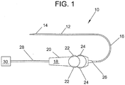
- FIG. 1 illustratively depicts an embodiment of the catheter assembly 10 including a catheter shaft 12.
- the catheter shaft 12 is a generally flexible elongate member having a distal segment 14, a proximal segment 16, and at least one lumen (not shown).
- the proximal segment 16 is attached to a handle 18.
- the handle 18 includes, by way of example, a housing 20, a first in-line steering actuator 22 (e.g., a knob), and a second steering actuator 24.
- the first and second actuators 22 and 24 are manipulated by a user moving an exposed control surface of the actuators 22 and 24 (using a finger/thumb) lengthwise along the length of the housing 20 of the handle 18 (as opposed to across the width of the handle 18).
- lengthwise along the housing includes the arrangement depicted in the exemplary embodiments (e.g., FIGs. 18 , 19 and 25 ) as well as other arrangements where the movement of an exposed control surface of the actuators is primarily along the lengthwise axis of the handle 18 (e.g., tilted by 30 degrees).
- Exposed control surface refers to a portion of the actuators 22 and 24 that is physically accessible to a user's finger/thumb through, for example, an opening in the housing 20.
- actuators 22 and 24 comprise rotatable knobs that rotate on an axis that is transverse to the lengthwise axis of the handle 18 when a user moves a thumb along the handle 18's length.
- thumb-controlled slider actuators replace the rotating knobs.
- the distal segment 14 is, by way of example, 10 cm long. However, an exemplary range for the length of the distal segment 14 is from 5 cm to 20 cm.
- a tip of the distal segment 14 has a generally smaller diameter than the diameter of the proximal segment 16 of the catheter shaft.
- the catheter shaft 12 is made, by way of example, of engineered nylon (such as Pebax® polyether block amide) and includes a tube or tubing, alternatively called a catheter tube or catheter tubing that has at least one lumen.
- the first and second steering actuators 22 and 24 are accessible (have exposed control surfaces through the housing 20) on two sides of the handle 18.
- a potential advantage of the depicted arrangement of the steering actuators 22 and 24 is the ability of a user to control the actuators 22 and 24 with a same hand that is holding the handle 18.
- a strain relief 26 protects the catheter shaft 12 at a point where the catheter shaft proximal segment 16 meets the handle 18.
- a cable 28 connects the handle 18 to a connector 30.
- the connector 30, which can be any of many possible configurations, is configured to interconnect with an ultrasound system for processing, storing, manipulating, and displaying data obtained from signals generated by a sensor mounted at the distal segment 14 of the catheter shaft 12.
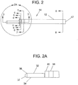
- FIGS. 2, 2A , 2B , and 8 illustrate a first embodiment of an ultrasound catheter 10 incorporating a handle and knob-based actuator control mechanism that supports single-handed position manipulation/control by a user of a sensor mounted at the distal segment 14 of the catheter shaft 12.
- the distal segment 14 of the catheter shaft 12 includes a rotatable tip 34 that extends from the distal segment 14 and rotates relative to an axis of the catheter shaft 12.
- the catheter shaft 12 has a lumen 47 as illustrated more clearly in FIGs. 7 and 8 .
- the rotatable tip 34 comprises a transducer probe assembly including transducers and a flex circuit.
- the rotatable tip 34 comprises a linearly arranged transducer array 32 including a set of transducer elements that are rectangular in shape, and the transducer probe assembly generally has a diameter that is smaller than the diameter of the distal segment 14 of the catheter shaft 12.
- rotatable tip 34 connects to a distal segment of the catheter 10 with a rotatably smooth sliding contact.
- the rotatable tip 34 includes a backing material 36.
- the rotatable tip 34 also includes a rounded tip portion 37 (atraumatic) to reduce the incidence of trauma to the human body as the tip 34 is fed into a patient.
- the rounded tip portion 37 is made from material such as a room temperature vulcanizing (RTV) elastomer or any silicone rubber.
- RTV room temperature vulcanizing
- the transducer array 32 is isolated from bodily fluids by the same materials as utilized in the rounded tip portion 37.
- the rotatable tip 34 is potentially rotatable by manual or motorized means.
- the rotatable tip 34 can be adapted to rotate in a variety of angular rotational ranges.
- the tip 34 is rotated bidirectionally in a 360° field of view.
- the tip 34 rotation is restricted to rotate bidirectionally in a limited rotational range, e.g., clockwise or counter-clockwise by 180° in each direction.
- the rotating tip 34 is rotated by manipulation of the first in-line steering actuator 22 of the handle 18, and is capable of approximately 180° of rotation in the clockwise direction and 180° rotation in the counter-clockwise direction.
- FIGS. 2B and 2C illustrate rotational steering affected by the actuator 22 of the catheter assembly 10.
- FIG. 2B illustrates the distal segment 14 in a central, neutral, or intermediate/relaxed position in between the two extremes of tip 34's rotation in relation to a distal segment termination 40 of the catheter shaft 12.
- the first steering actuator 22 a rotating knob
- the disclosed rotational steering mechanism facilitates smooth panning movement and pinpoint accuracy in imaging the desired tissue with the transducer array 32.
- the first steering actuator 22 e.g., rotating knob
- the first steering actuator 22 is moved in an opposing second rotational direction with respect to the handle 18.
- the exemplary transducer array 32 is a linear array of 64 transducer elements that are individually controlled to fire and sense echoes in phases, but can alternatively be any number of transducer elements, for example 16, 32, 128 or 256.
- the transducer array can be a curved array.
- the array can be a two-dimensional array, for example, two rows of 16 elements or four rows of 16 elements.
- the transducer array illustrated in this embodiment is coupled to a single multiplexer chip 46 controlling the transmission/reception of signals to/from the array 32.
- a multiplexer effectively reduces the number of wires passing through the majority of the length of the catheter shaft 12 by one half the transducer signal wires; for example, processing the signals received on 64 transducer elements with 32 electrical conduits instead of 64.
- further reduction is achieved by a factor of four, eight, or more.
- commercially-available intracardiac echocardiography catheter shafts are typically 8 French to 10 French in diameter
- the multiplexing in the present system provides for a catheter shaft that is 6 French or smaller in diameter. This results in a less invasive procedure and less trauma to the patient.
- the size of the puncture in the access artery or vein is smaller, allowing for faster healing, fewer complications, more space for other catheters and an ability to perform procedures in smaller patients such as pediatric patients.
- FIGs. 2B and 2C Though the single multiplexer chip 46 is illustrated in FIGs. 2B and 2C , more multiplexers can be used.
- the (reduction) ratio between transducer elements and wires can be increased to further reduce the number of wires within the catheter shaft 12, and thus reduce the catheter diameter.
- multiplexers are used to increase the number of transducer elements on an 8F to 10F catheter for greater than 64 transducer elements using 64 electrical wires.
- Each transducer directly connects to an electrical conductor/wire on a flex circuit before the multiplexer.
- a 256 element transducer array can be configured as a 1 x 256 linear array, a 2 x 128 1.5D array or alternatively as a 16 x 16 array for 3D imaging.
- a catheter with an array configured for 3D or three-dimensional imaging has the ability to be used in 3D applications, for example to guide a "smart" ablation or other therapeutic procedure to a specific point or area in a 3D map.
- a tracking device such as a wire loop or RF antenna for determining, positioning, and tracking the position and orientation of the catheter tip, a three dimensional map or image of the entire area of study can be obtained.
- the coordinates of the catheter tip 34 are downloaded and combined with multiple "slices" or frames of ultrasound image data.
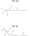
- FIGS. 2D and 2E illustrate distal segment 14 flexing steering affected by the second actuator 24 in the first embodiment.
- the catheter 12 is flexed, using the actuator 24, from a straight configuration as illustrated in FIG. 2D into a flexed steering configuration, as illustrated in Fig. 2E .
- the catheter 12's distal segment 14 is steerable into any number of flexed positions in between the straight configuration of Fig. 2D and the flexed configuration of Fig. 2E , and can even be flexed beyond the configuration of Fig. 2E .
- the catheter is capable of flexing past the 90° point in each direction and has an angular range of 0° to 150° from the straight or neutral configuration.
- the second direction is similar to what has been illustrated in FIG. 2E , and it can be appreciated that it is simply the mirror image of the configuration of Fig. 2E illustrated for the first direction.
- the second steering actuator 24 (e.g., knob) is turned in a first rotational direction with respect to the relatively fixed position handle 18. Rotating the actuator 24 in the first direction causes a first steering wire 56 (see, e.g., FIG. 8 ) to apply tension to a steering bulkhead 38 forcing the distal segment 14 of the catheter shaft 12 to bend at bending joint 15 (see, FIG. 2E ).
- the second steering actuator 24 is turned in an opposing second rotational direction with respect to the handle 18. This causes second steering wire 58 to apply tension to an opposite side of steering bulkhead 38, forcing the catheter to bend in an opposite direction at the bending joint 15.
- the catheter assembly 10 supports bidirectional flexed steering by at least 150 degrees in each direction from a neutral or straight catheter position. Using the combination of these two steering modes (rotational and flexing) is much more intuitive to the user than a steering mechanism based solely on either rotation or flexing - but not both.
- the catheter tip 34 is first placed into a desired location of the body, for example the right atrium of the heart. While visualizing the catheter tip position 34, such as with ultrasound or fluoroscopy, the second steering actuator 24 is adjusted until the catheter orientation is close to the desired orientation. The first steering actuator 22 is then adjusted so that the rotatable tip 34 points the transducer array 32 in the desired orientation for the target image plane.
- FIG. 9 illustrates the rotatable catheter tip 34 in place in a right atrium 72 of the heart.
- Second steering actuator 24 has already been adjusted to orient the catheter tip 34 in the correct tip flex position.
- an atrial septum 74 is not being imaged by ultrasound waves 76.
- a heart wall 70 is instead being imaged.
- the rotatable tip 34 is turned so that the ultrasound 76 impinges on the desired structure. This is done without torquing/twisting the catheter shaft 12.
- the adjustment of first steering actuator 22 is complete, and the rotatable tip 34 is now in position to image the atrial septum 74.
- FIGS. 3-8 and 18-21 illustrate detailed construction of the catheter assembly 10 of the first exemplary embodiment.
- FIG. 18 illustrates the handle 18 with the catheter shaft 12 and the strain relief 26 removed to show a proximal orifice 138. Cable wires 28 from the connector 30 extend through a proximal orifice 138. The catheter steering mechanisms and signal wire bundle extend through distal orifice 140.
- the contour of the handle facilitates one-hand use.
- the lower portion of the thumb and the two smallest fingers comfortably grip the handle 18 at a grip area 142.
- the shape of the handle 18 and positioning of the actuators 22 and 24 permits easy access for the thumb on the top of the handle and either the index or middle finger on the bottom of the handle to manipulate either the first steering actuator 22 or the second steering actuator 24 while maintaining hold on the grip area 142 of the handle 18.
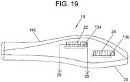
- FIG.19 illustratively depicts a top view of the handle in FIG. 18 to more clearly show the offset (staggered) alignment of the two actuators 22 and 24 with regard to a shared surface of the handle 18's housing 20.
- a first lock lever 134 and a second lock lever 136 protrude slightly above the outer edges/diameters of the first steering actuator 22 and second steering actuator 24. While in the resting locked position shown, the locking mechanisms controlled by the levers 134 and 136 do not allow the actuators 22 and 24 to be moved, thus maintaining the catheter 10 in its desired rotational and flex state.
- the associated one of the lock levers 134 and 136 is held down slightly by the thumb, releasing the corresponding locking mechanism and allowing the actuator to be moved (e.g., the knob rotates).
- the contours of the actuators 22 and 24 and lock levers 134 and 136 are configured so that it takes a small amount of force to hold the lock levers 134 and 136 down, and the thumb slides easily over the lock lever 134 and 136's surface while moving the corresponding actuator 22 or 24. After the actuator 22 or 24 is moved to the desired position and the thumb is taken off the lock lever 134 or 136, the corresponding lock automatically engages the actuator 22 or 24, holding the actuator 22 or 24 in the desired position until the next time it is to be moved.
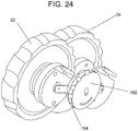
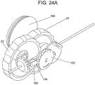
- FIG. 20 illustrates an exemplary configuration for the locking mechanism on the actuator 22 (taken along section line 20 in FIG. 19 ), though other configurations such as a clutch (see, e.g., FIGs. 24 and 24A described herein below) are contemplated in alternative embodiments.
- the first lock lever 134 is attached at one end to the handle 18 and has a free floating lock lever end 158 at the other end.
- the first lock lever 134 has a flexible portion 148, made, for example from a flexible polymer that is within its elastic limit over the flexible locked/unlocked displacement range used in the locking mechanism.
- Exemplary polymers include polycarbonate, acetal (such as Delrin® acetal resin), or any hard - yet flexible - plastic.
- FIG. 20 illustrates the lock 134 in an unlocked position in the handle 18. Note an upper thumb surface 150 and a lower finger surface 152.
- the first lock lever 134 contains lock teeth 144, which, when in the unlocked position, are not engaged with steering knob teeth 146. In this position while the first lock lever 134 is held down and the flexible portion 148 is flexed, the first actuator 22 is turned to the desired orientation or angular position. When the first lock lever 134 is released, lock teeth 144 engage with steering knob teeth 146 and the first actuator 22 is locked in its angular position.
- the embodiment shown in FIG. 20 utilizes the engagement of teeth as an actuator locking mechanism
- the teeth locking mechanism is replaced by a friction surface on the lock that when engaged to a surface of the actuator (e.g. the wheel), the friction surface creates a holding force.
- the friction on the steering actuator's surface can be created by using a rough surface, or an elastomeric material like silicone, thermoplastic elastomers or rubbers, or a tacky material.
- a radial engagement of the locking mechanism is shown, alternatively, the mechanisms as described can be incorporated in the axial direction.
- the locking mechanism is provided by a clutch that includes a tensioning knob 192, a friction cone 196 and the actuators22 and 24.
- the tensioning knob 192 generates a lateral displacement pushing the actuator 24 into further contact with the friction cone 196 resulting in a greater level of resistance to rotational motion.
- a similar cone exerts resistance on the actuator 22.
- the controllable additional resistance provides greater controllability to hold the actuators 22 and 24 against the restoring force presented by the steering lines that are in tension to maintain a desired position of the transducer probe mounted on the rotatable tip 34.
- FIG. 3 illustrates an exemplary embodiment of the rotatable tip 34.
- the rotatable tip 34 has a length that typically is 10 mm, and ranges from 5 mm to 20 mm.
- the exemplary transducer array 32 includes 64 transducer elements 44 mounted on a backing material 36. Inside the rotatable tip 34 is a stiffening member 42 proximate to the transducer elements 44.
- the stiffening member 42 can be a tube or rod, or can be of noncircular cross-section.
- Stiffening member 42 is made, for example, from a stiff material, such as a metal.
- the stiffening member 42 is made, for example, of a radiopaque metal, such as platinum, though stainless steel of sufficient wall thickness is sufficiently radiopaque.
- the transducer array 32 is large and stiff enough on its own, so that the stiffening member is not needed.
- a rotation point 51 represents the portion on the rotatable tip 34 that interfaces with the distal segment termination 40 on the distal segment 14 of the catheter shaft 12.
- the distal segment termination 40 is made, for example of engineered nylon (such as Pebax® polyether block amide).
- Attached to the rotatable tip in this embodiment is a torque member 50, made of a torquable tube, for example a braided or coil reinforced tube. It can also be made from a co-extruded tube. This tube can also act as electromagnetic interference (EMI) shielding.
- a cable bundle 48 is shown inside the torque member 50.
- the cable bundle 48 can be coaxial or simple wire, etc. Each of the cables of the cable bundle 48 is terminated to electrical connections 49 interfacing with the integrated circuit chip 46.
- FIGS. 3-8 illustrate, when the first steering actuator 22 is moved, end piece 40, steering bulkhead 38, and catheter shaft 12 remain rotationally static, but torque member 50, cable bundle 48, and rotatable tip 34 all rotate together to the desired angular position.
- a seal 45 such as an O-ring seal is placed at the rotation point 51 that allows the rotating components to rotate but serves as a barrier for blood to enter.
- a flexible sheath 41 connects and covers the tip 34 and distal segment 14 of the catheter 12 and provides for the tip 34 to rotate bidirectionally relative to the distal segment 14 by at least 360 degrees in each direction.
- the sheath 41 provides a seal for the tip and distal segment of the catheter 12 from bodily fluids. The ends of the sheath 41 are thermally joined/fitted to the tip 34 and distal segment 14 of the catheter 12 to form a seal.
- FIG. 21 is a detailed internal view of the first embodiment of the catheter handle 18 for use with a catheter having a combination of rotational steering and flexed steering.
- FIG. 21 illustrates a gearing interface that enables the first actuator 22 to turn torque member 50, which turns the cable bundle 48 and the rotatable tip 34.
- the lock levers and top housing half of handle 18 are not shown in order to more clearly illustrate the gearing interface.
- the first actuator 22 is rotated around a first shaft 182 causing actuator gear 164 to turn shaft gear 166.
- Shaft gear 166 is attached to a stiff torque shaft 168, which torque shaft is in turn attached to the torque member 50 in the catheter shaft 12.
- the torque member 50 is directly attached to shaft gear 166.
- the stiff torque shaft 168 is rotated clockwise.
- the stiff torque shaft 168 is rotated counter-clockwise.
- a beveled gear pair is illustrated, alternatively other gearing mechanisms can be used, such as a worm and wheel combination.
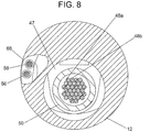
- FIG. 8 illustrates a cross section of the catheter shaft 12 over the majority of its length.
- the catheter shaft 12 includes central lumen 47 containing the wire bundle 48 including individual wires (e.g., 48a and 48b) and a shared lumen 68 through which the first steering wire 56 and the second steering wire 58 pass.
- Each steering wire can alternatively be within its own sheath (not shown), and both assemblies of wire and sheath are contained within the shared lumen 68.
- the catheter shaft 12's configuration at steering bulkhead 38 includes a cross section having central lumen 47, as well as first steering lumen 64 and second steering lumen 66, through which the first steering wire 56 and the second steering wire 58 pass individually.
- first steering lumen 64 and second steering lumen 66 through which the first steering wire 56 and the second steering wire 58 pass individually.
- the assemblies of wire and sheath transition from the shared lumen 68 to the separate steering lumens 64 and 66.
- FIG. 6 shows the portion of the distal segment termination 40, at which the distal ends of both of the steering wires 56 and 58 are located.
- Steering wires are alternatively called steering lines. Attached or secured to the ends of the steering wires are a first end cap 60 and a second end cap 62.
- a single steering wire turns around at the end piece 40, secures to the distal ends of the steering lumens by tension and adhesive for example, and runs continuously and bidirectionally inside the catheter shaft 12 from a steering control actuator on the handle 18 without using end caps 60 and 62 to accomplish flexed steering. This configuration can be repeated to enable flexing in two or more directions.
- the end caps 60 and 62 or alternatively the continuous loop steering wire are attached to the distal segment termination 40 using adhesive, solder, welding, brazing, swaging, crimping, or other attachment methods.
- the steering wires 56 and 58 are made, for example, of stainless steel or nitinol, but can also be made of aramid fiber (such as Kevlar® aramid fiber) or other high tensile types of line, and thus, the steering wires 56 and 58 are more generally called steering lines to include a wide variety of metal and non-metal materials.
- a first clearance lumen 52 and a second clearance lumen 54 allow the end caps 60 and 62 to fit within them, but alternatively the clearance lumens 52 and 54 can be formed permanently around the end caps.
- the diameter of each end cap 60 and 62 is larger than the diameter of each steering lumen 64 and 66.
- the end cap 60 By pulling the first steering wire 56 in a proximal direction, the end cap 60 impinges on distal segment of the steering lumen 64 of the steering bulkhead 38, causing this side of the catheter tubing to be stressed, thus causing the catheter shaft 12 to flex in a direction favoring this stress.
- steering wires 56 and 58 are integrally connected and wrap around a steering knob, when the first steering wire 56 is pulled, the second steering wire 58 is extended on the other side of the catheter shaft 12, resulting in a complimentary relaxation in the compliment wire and a smooth catheter profile for flexed steering.
- second steering wire 58 is pulled instead of first steering wire 56, the opposite occurs and the catheter shaft flexes in the opposite direction.
- the cable bundle 48 that includes wires 48a and 48b has a substantially uniform diameter and radial symmetry in the wire bundle 48, such that the bending stiffness is substantially uniform in any plane or surface in flexed steering of the catheter shaft 12 in the present catheter assembly 10.
- the cable bundle 48 is contained in free form tubing that is soft and compliant to enable the cable bundle to fit easily and symmetrically inside a lumen or cavity. For the operator of the present system this uniform bending stiffness enables easy and accurate control for improved manipulation or maneuverability to navigate and orientate the transducers to an optimal position and orientation to image a target area in an intracardiac chamber such as an atrial chamber.
- the shared lumen 68 is located more centrally in the catheter shaft 12.
- the steering lumens 64 and 66 pass through the central lumen 47 of the catheter 12, and there is no shared lumen.
- FIG. 21 an exemplary arrangement is illustrated for flexed steering of the catheter shaft 12's distal segment 14.
- Second steering actuator 24 is rotated around second shaft 184 causing first steering pulley 170 to rotate eccentrically and second steering pulley 172 to rotate concentrically.
- the knobs and steering pulleys rotate bidirectionally.
- First steering line 174 is wrapped around both pulleys 170 and 172 in a switch back or "z" configuration.
- One end of the steering line 174 terminates at an anchor spring 181 that secures to the handle.
- first steering line 174 is secured inside the housing 20, and is attached to an anchor spring 181 to maintain tension.
- anchor spring 181 to maintain tension.
- the effective length of the first steering line 174 is changed (i.e., increasing or decreasing) depending on the direction the knob is turned.
- an upper distal pulley 160 and a lower distal pulley 162 help guide the steering line 174 as it extends into the catheter shaft 12.
- a second steering line is a mirror image of the first steering line arrangement already described.
- the steering line 174 alternatively wraps around a steering pulley 172 and a cleat 173 or alternatively called a tie-off mechanism attached to the steering pulley 172 such that steering line 174 departs from the steering pulley 172 and returns to the distal segment 14 of the catheter 12.
- the cleat 173 provides for proper tension to be set and the reduction or elimination of slack in the steering line 174.
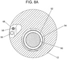
- FIG. 8A An alternative embodiment of the catheter assembly is illustrated in FIG. 8A .
- the embodiment of FIG. 8A includes a torque cable 90 which allows the conductors, shown as a flat conductor assembly 92, to be located outside the torque cable 90, not inside a lumen.
- the torque cable 90 is made from multiple layer multifilar coils. The advantage to this configuration is that a cable of this type can be made to be very straight and thus have a better fine torque response than a torque tube configuration.
- the flat conductor assembly 92 can be made from a flex circuit ribbon.
- the conductor assembly 92 and torque cable 90 have radial symmetry in the catheter shaft such that this configuration has the advantage of substantially uniform bending stiffness in any bending plane in flexed steering as already described.
- a surrounding tube 94 is made from shrink tubing, and holds the entire assembly together.
- Another advantage to this embodiment is that the torque cable 90 can extend further into the rotatable tip 34, to secure it, and also allows for easier routing of the conductors at the tip 34 for electrical connection to the cable bundle 48. Electrical connection can be achieved by micro-welding or soldering, or other known methods.
- FIGS. 11-14 illustratively depict components of an exemplary tip 34 that includes a transducer array for use in ultrasound catheters of size 6F and smaller.
- FIG. 11 illustrates a flex circuit 77 component of the tip 34.
- each transducer element can be independently programmed to fire.
- a substrate 82 is made, for example, from a thin and flexible material, such as polyimide. Some examples of polyimide are Kapton® polyimide or Upilex-S® polyimide.
- the substrate can also serve as an ultrasonic matching layer.
- Conductive tracings 78 and 80 create multiple conductors on the substrate 82 which is a part of the flex circuit. Each conductive tracing provides a single electrical conduit for each transducer.
- transducer elements are attached to the flex circuit 77.
- a piezoelectric material block is attached, and then kerfs are made with, for example, a dicing saw, to create the individual transducer elements.
- One or more integrated circuit or chip 46 is connected to the conductive tracings 78 and 80. In a specific configuration as illustrated in FIG. 12 the chip 46 is connected between the two groups of conductive tracings 78 and 80.
- other devices such as a wire loop or RF antenna 35 (see, e.g., FIG. 3 ) in the tip 34 is connected to conductive tracings 78 and 80 via terminals 79. Terminals 49 allow electrical connection of the aforementioned conductive tracings 78 and 80 to the cable bundle 48.
- An example of a flex circuit that includes terminals 79 but no integrated circuit is illustrated in FIG. 12 .
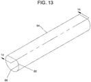
- FIGS. 13 and 14 the assembly of FIG. 12 is rolled into a rolled transducer assembly 84 having a D-shaped cross-section 86 and a seam 88.
- a distal segment of the flex circuit is rolled over a stiffening member 42 (see, FIG. 3 ) that is proximate to and extends alongside the array of transducers.
- the backing material 36 is injected inside the rolled transducer assembly 84.
- An additional matching layer can be formed over the assembly to provide better acoustic matching between the transducer piezoelectric material and the target tissue as well as the transmission medium.
- RTV silicone is one such material that can be used.
- the D-shape cross section allows the linear layout of the transducer elements and uniform wall thickness of the matching layer due to the flat top for even and controlled focusing.
- the tip 34 has a proximal portion which has a rounded shape and encapsulates the proximal portion of the flex circuit.
- Exemplary transducers for ICE have a typical thickness of approximately 0.28 mm in the piezoelectric material to enable an 8 MHz ultrasound signal to be generated and transmitted at a typical velocity of 1500 m/sec through blood.
- the transducer thickness can be of various thicknesses ranging approximately from 0.56 mm to 0.19 mm to generate sufficient penetration depth in tissue imaging.
- the thickness of the transducers can be adjusted for the frequency of sound in the transmission medium for the desired penetration depth in any tissue imaging.
- Image intensity can be adjusted by driving voltage on the transducers.
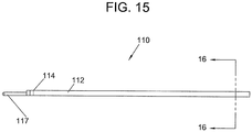
- FIGS. 15-16 illustrate an alternative embodiment of the catheter assembly 10.
- Ultrasound catheter 110 includes a catheter shaft 112 and a distal segment 114 having a non-rotating tip 117.
- Non-rotating tip 117 has a structure similar to the rotatable tip 34 but differs in its connection with the distal segment of the catheter.
- Non-rotating tip 117 connects integrally to the distal segment 114 of the catheter shaft 112 and does not rotate relative to the catheter shaft 112.
- FIG. 16 illustrates two orthogonally arranged planar steering controls. First plane steering lines 119 and 121 and second plane steering lines 123 and 125 pass through four steering lumens in shaft 129.
- a two-material shaft is provided to overcome stiffness of a high lubricity material.
- the shaft 129 is extruded so that each lumen has a lumen liner 127 consisting of a material that is different from the material of the shaft 129.
- the material of the lumen liners is a high lubricity material that allows the steering lines to move axially with minimal frictional resistance. If the entire shaft were to be extruded from the material used in the lumen liners, the high stiffness of the lubricious material used would cause the shaft to be dangerously inflexible.
- the rest of the shaft can be made from a sufficiently flexible material to optimize catheter shaft flexibility, ease of use and safety in the patient.
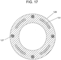
- FIG. 17 shows an alternative tubing extrusion that includes embedded conductors 131 within the tubing wall and extending the length of the tubing.
- the wall thickness of the tubing can be increased for strength.
- the conductors are well placed for making electrical terminations and further connections to the conductive tracings of the flex circuit.
- a flat ribbon of several conductors can be used.
- four groups of eight wire ribbons are illustrated.
- FIG. 22 illustrates an alternative embodiment of the handle 18 for use with the catheter embodiment of FIGS. 15-17 .
- Second steering actuator 24 works in the same manner as that of FIG. 21 .
- the embodiment of FIG. 22 contains the same mechanism in both actuators for flexed steering in two different, orthogonal, planes or surfaces.
- One actuator operates the catheter flexing in a first plane and the other knob operates the catheter flexing in a second plane.
- First steering actuator 22 operates third steering pulley 178 and fourth steering pulley 180, and its own steering lines (not shown).
- FIG. 23 illustrates a similar embodiment to that of FIG. 22 .
- each steering knob instead rotates first and second large pulleys 186 and 188.
- a single steering line is used from the distal end in one lumen, then proximally and around the large pulley, and then distally again, terminating at the distal end of the other lumen.
- the grooves of each pulley are coated with a low lubricity, high friction material, such as silicone elastomer, such that no slippage occurs on the steering line.
- the steering line is permanently attached to the pulley instead of being frictionally coupled.
- tensioners (not shown) consisting of secondary pulleys spring loaded on an arm, can be used to minimize line slack.
- a three-way steering catheter is made that combines the two orthogonally arranged flexed steering of FIGS. 15-17 with the rotational steering associated with Figs. 1-14 .
- the three steering modes in this case, for example, are flexed steering left-to-right, flexed steering anterior-to-posterior, and tip rotation.
- An embodiment of the three plane steering catheter includes the configuration as already described in FIGS. 15-17 and adding a torque member connected to the rotating tip 14 on the distal side and to a third shaft gear assembly on the handle.
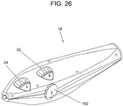
- FIGS. 24 , 24A and 26 illustrate a clutch mechanism facilitated by the interaction of the following components: a tensioning knob 192, a cam 194 (or screw), actuator 24, a thrust washer 186 and a friction cone 196 (not shown in FIG 24 ).
- Actuators 22 and 24 each are fit with friction cones (only friction cone 196 for actuator 24 is shown in the illustrative example in FIG. 24A ).
- the thrust washer 186 acts as an interface between the cam 194 and the actuator 22.
- Rotating the tensioning knob 192 in a first direction results in the application of lateral displacement to actuators 22 and 24 which, in turn, increases the amount of contact area between the actuators 22 and 24 and friction cones (e.g. cone 196 for actuator 24).
- the increase in the contact area between the actuators and their corresponding friction cones results in increased resistance to rotational motion of the actuators -- which in turn results in increased resistance to the restoring force presented by the steering lines that are in tension.
- the clutch mechanism acts to create a slight and variable hold of a control actuator such as actuators 22 and 24 such that an ideal position can be achieved by the clinician. By use of this variable resistance functionality the clinician can find the ideal position to do his procedure and increase the resistance to motion by further tightening the tensioning and thereby holding its set position.
- the resistance to movement functionality is achieved by three basic components: the friction cone 196 that is anchored to the handle 18; actuators 22 and/or 24 that have surfaces which match the angle of the friction cones and are free to turn as well as move slightly axially onto and off of the friction cone 196; and the cam 194 (or screw) that generates the side load and lateral motion of the actuators 22 and 24 onto the friction cones such as cone 196.
- FIG. 26 provides an exemplary exterior view of the handle 18 including the tensioning knob 192 for applying a varying degree of resistance to movement of the actuators 22 and 24. Placing the tensioning knob 192 on a side of the handle 18 facilitates single-handed operation of the catheter assembly 10 via the exposed control surfaces of the actuators 22 and 24 and the tensioning knob 192.
- the tensioning knob 192 comprises a slider external control surface that provides a variable amount of resistance to movement of the actuators 22 and 24 by moving the slider within a sliding range along the side of the housing 20 of the handle 18.
- any of the handle designs can be combined with methods for determining exactly the tip configuration of the catheter.
- magnetic tape with circumferential position coordinates is attached to each of the two steering knobs.
- a multiplicative factor is included in these coordinates that transforms the circumferential displacement of the knob to either the angular displacement of the tip flex or the angular displacement of the rotatable tip rotation.
- a reusable magnetic reader is plugged in to the handle and the position or angular data is retrieved by the ultrasound system, or by a co-registration system coupled to the ultrasound system.
- RF backscatter based tissue characterization is used in IVUS to determine plaque type (fibrous, fibro-lipidic, calcified, necrotic, etc.). This type of analysis is also known as Virtual Histology. Using this imaging technique with myocardial tissue instead of atherosclerotic plaque, different types of myocardial tissue can be identified, including for example, healthy myocardium, dead myocardium, or diseased myocardium. Also, ablated and non-ablated tissue can be identified, such as the tissue in the pulmonary veins or other cardiac tissue. RF backscatter tissue characterization can also be used to more correctly identify the extent of calcification on diseased heart valves.
- An alternative steerable catheter utilizes a backbone of two-way shape memory.
- Current is selectively sent through different sections of a two-way shape memory metal lattice structure, causing phase change due to differential heating. For example, when current is sent through nodes on one side, the distal segment 14 of the catheter shaft 12 bends in a first direction. When current is turned off in nodes on the first side and turned on in nodes on a second side, the tip bends in a second direction, different from the first.
- Another alternative steerable catheter utilizes magnetic rings.
- the catheter has one or more magnetic bands at the tip.
- a magnetic guidance system such as that made by Stereotaxis
- the distal segment 14 of the catheter shaft 12 can be made to flex in reaction to specific magnetic fields that are produced.
- Another alternative steerable catheter utilizes a micromotor. Instead of the rotatable tip being rotated in one direction or the other by turning a knob manually in the handle, a motor in the handle 18 rotates the assembly by pushing either a clockwise or counter-clockwise button. Alternatively, a micromotor is embedded in the tip and when a button in the handle is pressed, the micromotor rotates the rotatable tip.
- Another alternative steerable catheter tip utilizes micromachines.
- An articulation or microgearing system is constructed in the distal end of the catheter using nanotechnology micro parts.
- Another alternative steerable catheter utilizes spinning top articulation.
- the distal end of the catheter shaft 12 has two opposing spiral grooves in the wall.
- a rotatable tip is attached to a push rod, not a torque member.
- the rotatable tip has two tabs, one that slidably fits into each of the grooves. When the rod is pushed, the rotatable tip rotates to the right. When the rod is pulled, the rotatable tip rotates to the left.
- Another alternative steerable catheter utilizes spinning top articulation combined with piezo power.
- a piezoelectric material is used as a mount for a transducer array at the tip of the catheter shaft 12. By activating the mount with a voltage, the mount oscillates a few degrees (for example 10 degrees), causing the transducer array to sweep back and forth, creating a 3D image.
- Another alternative steerable catheter utilizes a superelastic material. Inside the catheter shaft 12 is a shaped mandrel of superelastic material which has a sliding stiff tube over it. When the stiff tube is pulled back, the superelastic mandrel takes its curved shape. When the stiff tube is advanced, the superelastic mandrel is straightened, causing the shaft to straighten with it. The distal end of the superelastic shaped mandrel is, by way of example, flattened.
- a polymeric catheter shaft is pre-shaped. It contains a lumen that is filled with a material such as a mineral or vegetable oil that is nontoxic and can be sterilized.
- a pistoning mandrel is slidable within the lumen.
- a sealing stopper made from, for example, a ruby or ceramic ball for ultra low friction.
- the ball sealably slides within the lumen, increasing the pressure of the oil within the lumen and causing a curved tube to straighten, as in a Bourdon tube. Pulling on the mandrel lowers the pressure and allows the tubing to return to its shaped configuration.
Landscapes
- Health & Medical Sciences (AREA)
- Life Sciences & Earth Sciences (AREA)
- Surgery (AREA)
- Engineering & Computer Science (AREA)
- Medical Informatics (AREA)
- General Health & Medical Sciences (AREA)
- Veterinary Medicine (AREA)
- Public Health (AREA)
- Biomedical Technology (AREA)
- Heart & Thoracic Surgery (AREA)
- Nuclear Medicine, Radiotherapy & Molecular Imaging (AREA)
- Molecular Biology (AREA)
- Animal Behavior & Ethology (AREA)
- Physics & Mathematics (AREA)
- Biophysics (AREA)
- Pathology (AREA)
- Radiology & Medical Imaging (AREA)
- Gynecology & Obstetrics (AREA)
- Mechanical Engineering (AREA)
- Orthopedic Medicine & Surgery (AREA)
- Vascular Medicine (AREA)
- Ultra Sonic Daignosis Equipment (AREA)
Description
- The present invention generally relates to ultrasound catheters. More specifically, the present invention pertains to an ultrasound intracardiac echocardiography (ICE) catheter with flexed steering to transmit ultrasound and receive echo in intracardiac diagnostics.
- Diagnostic and therapeutic ultrasound catheters have been designed for use inside many areas of the human body. In the cardiovascular system, two common diagnostic ultrasound methods are intravascular ultrasound (IVUS) and intracardiac echocardiography (ICE). Typically a single rotating transducer or an array of transducer elements is used to transmit ultrasound at the tips of the catheters. The same transducers (or separate transducers) are used to receive echoes from the tissue. A signal generated from the echoes is transferred to a console which allows for the processing, storing, display, or manipulation of the ultrasound-related data.
- IVUS catheters are typically used in the large and small blood vessels (arteries or veins) of the body, and are almost always delivered over a guidewire having a flexible tip. ICE catheters are usually used to image the chambers of the heart and surrounding structures. Commercially-available ICE catheters are not designed to be delivered over a guidewire, but instead have distal ends which can be articulated by a steering mechanism located in a handle at the proximal end of the catheter.
- One type of ICE catheter (EP Medsystems ViewFlex™ Intracardiac Ultrasound Deflectable catheter) has a distal articulation in a single plane (both directions), operated by a single wheel that rotates about the lengthwise axis of the handle. The wheel is turned to a specific position for the desired catheter shape, staying in place due to the inherent friction on the wheel mechanism. The catheter is torquable, and can be rotated with the handle to aid steering in a second plane. The motions required to simultaneously torque and rotate the catheter often require two-handed operation.
- Another type of ICE catheter (Siemens/ACUSON AcuNav™ Ultrasound Catheter) has an additional steering plane, and each steering plane is utilized by turning one of two corresponding wheels on the handle. These wheels rotate about the lengthwise axis of the handle. A third wheel, which also rotates about the lengthwise axis of the handle, is a locking mechanism for freezing each of the two steering wheels in its respective orientation. The entire catheter need not be torqued. However, unlocking the locking mechanism unlocks the steering wheels for both of the steering planes/wheels at the same time. While the physician is steering the catheter in one plane, the orientation of the other plane may spontaneously change to an undesired orientation. Though the two steering planes allow a large combination of possible catheter configurations, the simultaneous steering of both planes in order to achieve a specific configuration can be difficult to visualize and coordinate. Further the signal lines are formed on a flex cable with a rectangular cross-section and assembled without radial symmetry. The flex cable runs along the length of the AcuNav™ catheter behind the ultrasound transducers, causing the catheter to have different bending stiffness along different bending planes of the catheter, making the catheter more difficult to manipulate or maneuver.
- Both the ViewFlex and the AcuNav catheters utilize a linear array of multiple transducer elements, e.g., 64 elements, at their tips. The design of the catheter requires 64 channels in the ultrasound console in order to process each element in parallel. This requires that the catheter shaft contain at least that many conductors to carry the signals to the proximal end. There is a limit (due to conductor size, dielectric properties, etc.) to how small the catheter shaft can be made using this design. For example, the AcuNav is currently an 8 F catheter and the ViewFlex is a 9 F catheter. In order to place these catheters within the vascular system of the patient, punctures of a diameter larger than the catheter shaft size are required. These are relatively large punctures, especially when inserted arterially, and may take longer to close or heal as well as have a greater number of related complications. In addition, because many of the cases performed in the cardiac catheter laboratory or electrophysiology laboratory require multiple catheters, having a large diameter ICE catheter can cause a "traffic jam" inside the anatomy.
US 5,853,368 discloses an ultrasound imaging catheter with controls for the manipulation of the tip of the catheter. The controls are located on top of the handle in lengthwise direction. - A hand-operated catheter assembly is useful in a variety of applications including ICE procedures for imaging intracardiac and surrounding structures with a heightened level of control and ease of use. More particularly a hand-operated ultrasound catheter assembly is described herein that includes an elongate flexible shaft having a proximal end and a distal end. An ultrasonic transducer is mounted proximate the distal end to facilitate acquiring raw ultrasound image data. In accordance with exemplary embodiments described herein the catheter assembly also includes a handle coupled to the shaft near the proximal end.
- The handle includes a number of features for improved, single-handed control of the position of the ultrasonic transducer. A housing of the handle has an elongate shape adapted for hand-held operation. The handle also includes a first steering actuator for controlling a position of the ultrasonic transducer. In accordance with illustrative embodiments, the first steering actuator affects repositioning the ultrasonic transducer by repositioning an exposed control surface of the first steering actuator lengthwise along the housing of the handle. In accordance with illustrative embodiments the handle also includes a second steering actuator for controlling the position of the ultrasonic transducer. The second steering actuator affects repositioning the ultrasonic transducer by repositioning an exposed second control surface of the second steering actuator lengthwise along the housing.
- The steering actuators are used to position the ultrasonic transducer in potentially a variety of ways. A first way involves rotating a tip at the end of the catheter to face the transducer in a particular direction. A second way involves flexing a distal segment of the catheter shaft upon which the transducer is mounted. A locking mechanism is also provided in accordance with particular exemplary embodiments to hold the actuators in a desired position.
- The various features of the present invention and the manner of attaining them will be described in greater detail with reference to the following description, claims, and drawings, wherein reference numerals appear in more than one drawing, where appropriate, to indicate a correspondence between the referenced items, and wherein:
-
FIG. 1 is an illustration of an intracardiac echocardiography (ICE) catheter; -
FIG. 2 is an illustration of the distal end of the ICE catheter; -
FIG. 2A is a detail view of the distal end of the ICE catheter; -
FIGS. 2B and 2C are illustrations of rotational steering mode of an ICE catheter; -
FIGS. 2D and 2E are illustrations of a flexing steering mode of an ICE catheter; -
FIG. 3 is a section taken alongline 3 inFIG. 2 ; -
FIG. 4 is a cross-section taken alongline 4 inFIG. 2 ; -
FIG. 5 is a cross-section taken alongline 5 inFIG. 2 ; -
FIG. 6 is a cross-section taken alongline 6 inFIG. 2 ; -
FIG. 7 is a cross-section taken alongline 7 inFIG. 2 ; -
FIG. 8 is a cross-section taken alongline 8 inFIG. 2 ; -
FIG. 8A is an alternative embodiment of the catheter inFIG. 8 ; -
FIGS. 9 and10 illustrate a rotational steering catheter being used to image structures in the heart; -
FIG. 11 is an illustration of a flex circuit for use in an ultrasound catheter; -
FIG. 12 is an illustration of a transducer/circuit assembly for use in a linear array ultrasound catheter; -
FIG. 13 illustratively depicts the transducer/circuit assembly ofFIG. 12 in a rolled or wrapped configuration; -
FIG. 14 is a cross-section of the rolled transducer/circuit assembly ofFIG. 13 taken alongline 14; -
FIG. 15 is an alternative embodiment of an ICE catheter; -
FIG. 16 is a cross-section of the catheter shaft of the catheter inFIG. 15 taken alongline 16; -
FIG. 17 is a cross-section of an alternative shaft of an ICE catheter; -
FIG. 18 is a detailed illustration of a catheter handle; -
FIG. 19 is a top view of the same catheter handle; -
FIG. 20 is a cross-sectional view of the locking/unlocking mechanism in one of the knobs of the catheter handle; -
FIG. 21 is a detailed internal view of a first embodiment of the catheter handle for use with a catheter having a combination of rotational steering and flexed steering; -
FIG. 22 is a detailed view of a second embodiment of the catheter handle for use with a catheter having two-plane flexed steering; -
FIG. 23 is a detailed view of a third embodiment of the catheter handle for use with a catheter having two plane flex steering and showing further detail of the locking/unlocking mechanism. -
FIG. 24 and24A is a detailed view of a clutch in relation to the knobs. -
FIG. 25 is a detailed view of a cleat or tie-off mechanism attached to a knob. -
FIG. 26 is a detailed view of a handle with two knobs and a clutch. - It should be understood that the sizes of the different components in the figures may not be in proportion and are shown for visual clarity and for the purpose of explanation.
- The following embodiments are related to an
ultrasound catheter assembly 10. For the purpose of illustration theultrasound catheter assembly 10 is described in the context of an ultrasound catheter system for use as an intracardiac echocardiography (ICE) catheter. However, other applications of the disclosed catheter assembly are contemplated for alternative embodiments. -
FIG. 1 illustratively depicts an embodiment of thecatheter assembly 10 including acatheter shaft 12. Thecatheter shaft 12 is a generally flexible elongate member having adistal segment 14, aproximal segment 16, and at least one lumen (not shown). Theproximal segment 16 is attached to ahandle 18. Thehandle 18 includes, by way of example, ahousing 20, a first in-line steering actuator 22 (e.g., a knob), and asecond steering actuator 24. - The first and
second actuators actuators 22 and 24 (using a finger/thumb) lengthwise along the length of thehousing 20 of the handle 18 (as opposed to across the width of the handle 18). As used herein the term "lengthwise along the housing" includes the arrangement depicted in the exemplary embodiments (e.g.,FIGs. 18 ,19 and25 ) as well as other arrangements where the movement of an exposed control surface of the actuators is primarily along the lengthwise axis of the handle 18 (e.g., tilted by 30 degrees). "Exposed control surface" refers to a portion of theactuators housing 20. Furthermore, a variety of actuator mechanisms are envisioned foractuators first actuator 22 andsecond actuator 24 comprise rotatable knobs that rotate on an axis that is transverse to the lengthwise axis of thehandle 18 when a user moves a thumb along thehandle 18's length. In alternative embodiments, thumb-controlled slider actuators replace the rotating knobs. - The
distal segment 14 is, by way of example, 10 cm long. However, an exemplary range for the length of thedistal segment 14 is from 5 cm to 20 cm. A tip of thedistal segment 14 has a generally smaller diameter than the diameter of theproximal segment 16 of the catheter shaft. Thecatheter shaft 12 is made, by way of example, of engineered nylon (such as Pebax® polyether block amide) and includes a tube or tubing, alternatively called a catheter tube or catheter tubing that has at least one lumen. - In the illustrative example in
FIG. 1 , the first andsecond steering actuators handle 18. A potential advantage of the depicted arrangement of thesteering actuators actuators handle 18. Astrain relief 26 protects thecatheter shaft 12 at a point where the catheter shaftproximal segment 16 meets thehandle 18. Acable 28 connects thehandle 18 to aconnector 30. Theconnector 30, which can be any of many possible configurations, is configured to interconnect with an ultrasound system for processing, storing, manipulating, and displaying data obtained from signals generated by a sensor mounted at thedistal segment 14 of thecatheter shaft 12. -
FIGS. 2, 2A ,2B , and8 illustrate a first embodiment of anultrasound catheter 10 incorporating a handle and knob-based actuator control mechanism that supports single-handed position manipulation/control by a user of a sensor mounted at thedistal segment 14 of thecatheter shaft 12. Turning toFIGs. 2 and 2A , thedistal segment 14 of thecatheter shaft 12 includes arotatable tip 34 that extends from thedistal segment 14 and rotates relative to an axis of thecatheter shaft 12. Thecatheter shaft 12 has alumen 47 as illustrated more clearly inFIGs. 7 and8 . - In the illustrative embodiment depicted in
FIGs. 2 and 2A therotatable tip 34 comprises a transducer probe assembly including transducers and a flex circuit. By way of example, therotatable tip 34 comprises a linearly arrangedtransducer array 32 including a set of transducer elements that are rectangular in shape, and the transducer probe assembly generally has a diameter that is smaller than the diameter of thedistal segment 14 of thecatheter shaft 12. Furthermorerotatable tip 34 connects to a distal segment of thecatheter 10 with a rotatably smooth sliding contact. Therotatable tip 34 includes abacking material 36. Therotatable tip 34 also includes a rounded tip portion 37 (atraumatic) to reduce the incidence of trauma to the human body as thetip 34 is fed into a patient. The roundedtip portion 37 is made from material such as a room temperature vulcanizing (RTV) elastomer or any silicone rubber. Thetransducer array 32 is isolated from bodily fluids by the same materials as utilized in the roundedtip portion 37. - The
rotatable tip 34 is potentially rotatable by manual or motorized means. Therotatable tip 34 can be adapted to rotate in a variety of angular rotational ranges. For example, in one embodiment thetip 34 is rotated bidirectionally in a 360° field of view. Alternatively thetip 34 rotation is restricted to rotate bidirectionally in a limited rotational range, e.g., clockwise or counter-clockwise by 180° in each direction. In a first embodiment, the rotatingtip 34 is rotated by manipulation of the first in-line steering actuator 22 of thehandle 18, and is capable of approximately 180° of rotation in the clockwise direction and 180° rotation in the counter-clockwise direction. -
FIGS. 2B and 2C illustrate rotational steering affected by theactuator 22 of thecatheter assembly 10.FIG. 2B illustrates thedistal segment 14 in a central, neutral, or intermediate/relaxed position in between the two extremes oftip 34's rotation in relation to adistal segment termination 40 of thecatheter shaft 12. In order to rotationally steer thetransducer array 32 to the rotated position illustrated inFig, 2C , thefirst steering actuator 22, a rotating knob, is turned in a first rotational direction with respect to the relatively fixed position of thehandle 18. The disclosed rotational steering mechanism facilitates smooth panning movement and pinpoint accuracy in imaging the desired tissue with thetransducer array 32. To rotate thecatheter tip 34 in the opposite direction (e.g., counter-clockwise), the first steering actuator 22 (e.g., rotating knob) is moved in an opposing second rotational direction with respect to thehandle 18. - In the illustrative embodiment depicted in
FIG. 2A , theexemplary transducer array 32 is a linear array of 64 transducer elements that are individually controlled to fire and sense echoes in phases, but can alternatively be any number of transducer elements, for example 16, 32, 128 or 256. Alternatively the transducer array can be a curved array. In addition, the array can be a two-dimensional array, for example, two rows of 16 elements or four rows of 16 elements. - The transducer array illustrated in this embodiment is coupled to a
single multiplexer chip 46 controlling the transmission/reception of signals to/from thearray 32. In an exemplary embodiment a multiplexer effectively reduces the number of wires passing through the majority of the length of thecatheter shaft 12 by one half the transducer signal wires; for example, processing the signals received on 64 transducer elements with 32 electrical conduits instead of 64. In yet other exemplary multiplexers, further reduction is achieved by a factor of four, eight, or more. Whereas commercially-available intracardiac echocardiography catheter shafts are typically 8 French to 10 French in diameter, the multiplexing in the present system provides for a catheter shaft that is 6 French or smaller in diameter. This results in a less invasive procedure and less trauma to the patient. As a result of the smaller diameter of the catheter shaft of the present system, the size of the puncture in the access artery or vein (e.g., femoral vein, femoral artery, subclavian vein, jugular vein) is smaller, allowing for faster healing, fewer complications, more space for other catheters and an ability to perform procedures in smaller patients such as pediatric patients. - Though the
single multiplexer chip 46 is illustrated inFIGs. 2B and 2C , more multiplexers can be used. - Also, the (reduction) ratio between transducer elements and wires can be increased to further reduce the number of wires within the
catheter shaft 12, and thus reduce the catheter diameter. Alternatively, multiplexers are used to increase the number of transducer elements on an 8F to 10F catheter for greater than 64 transducer elements using 64 electrical wires. Each transducer directly connects to an electrical conductor/wire on a flex circuit before the multiplexer. For example a 256 element transducer array can be configured as a 1 x 256 linear array, a 2 x 128 1.5D array or alternatively as a 16 x 16 array for 3D imaging. A catheter with an array configured for 3D or three-dimensional imaging has the ability to be used in 3D applications, for example to guide a "smart" ablation or other therapeutic procedure to a specific point or area in a 3D map. By placing in the tip 34 a tracking device such as a wire loop or RF antenna for determining, positioning, and tracking the position and orientation of the catheter tip, a three dimensional map or image of the entire area of study can be obtained. The coordinates of thecatheter tip 34 are downloaded and combined with multiple "slices" or frames of ultrasound image data. -
FIGS. 2D and 2E illustratedistal segment 14 flexing steering affected by thesecond actuator 24 in the first embodiment. Thecatheter 12 is flexed, using theactuator 24, from a straight configuration as illustrated inFIG. 2D into a flexed steering configuration, as illustrated inFig. 2E . In addition, thecatheter 12'sdistal segment 14 is steerable into any number of flexed positions in between the straight configuration ofFig. 2D and the flexed configuration ofFig. 2E , and can even be flexed beyond the configuration ofFig. 2E . The catheter is capable of flexing past the 90° point in each direction and has an angular range of 0° to 150° from the straight or neutral configuration. The second direction is similar to what has been illustrated inFIG. 2E , and it can be appreciated that it is simply the mirror image of the configuration ofFig. 2E illustrated for the first direction. - To affect flexing the
distal segment 14 in the manner described above, the second steering actuator 24 (e.g., knob) is turned in a first rotational direction with respect to the relatively fixed position handle 18. Rotating theactuator 24 in the first direction causes a first steering wire 56 (see, e.g.,FIG. 8 ) to apply tension to asteering bulkhead 38 forcing thedistal segment 14 of thecatheter shaft 12 to bend at bending joint 15 (see,FIG. 2E ). In order to flex the catheter in the opposite direction, thesecond steering actuator 24 is turned in an opposing second rotational direction with respect to thehandle 18. This causessecond steering wire 58 to apply tension to an opposite side of steeringbulkhead 38, forcing the catheter to bend in an opposite direction at the bending joint 15. Thecatheter assembly 10, by way of example, supports bidirectional flexed steering by at least 150 degrees in each direction from a neutral or straight catheter position. Using the combination of these two steering modes (rotational and flexing) is much more intuitive to the user than a steering mechanism based solely on either rotation or flexing - but not both. In an example of a method for using thecatheter assembly 10 having both rotational and flex steering, thecatheter tip 34 is first placed into a desired location of the body, for example the right atrium of the heart. While visualizing thecatheter tip position 34, such as with ultrasound or fluoroscopy, thesecond steering actuator 24 is adjusted until the catheter orientation is close to the desired orientation. Thefirst steering actuator 22 is then adjusted so that therotatable tip 34 points thetransducer array 32 in the desired orientation for the target image plane. -
FIG. 9 illustrates therotatable catheter tip 34 in place in aright atrium 72 of the heart.Second steering actuator 24 has already been adjusted to orient thecatheter tip 34 in the correct tip flex position. As illustrated inFIG. 9 the desired structure to be imaged, anatrial septum 74, is not being imaged by ultrasound waves 76. Aheart wall 70 is instead being imaged. By manipulatingfirst steering actuator 22, therotatable tip 34 is turned so that theultrasound 76 impinges on the desired structure. This is done without torquing/twisting thecatheter shaft 12. InFig. 10 , the adjustment offirst steering actuator 22 is complete, and therotatable tip 34 is now in position to image theatrial septum 74. -
FIGS. 3-8 and18-21 illustrate detailed construction of thecatheter assembly 10 of the first exemplary embodiment.FIG. 18 illustrates thehandle 18 with thecatheter shaft 12 and thestrain relief 26 removed to show aproximal orifice 138.Cable wires 28 from theconnector 30 extend through aproximal orifice 138. The catheter steering mechanisms and signal wire bundle extend throughdistal orifice 140. - It can be seen that the contour of the handle facilitates one-hand use. The lower portion of the thumb and the two smallest fingers comfortably grip the
handle 18 at agrip area 142. The shape of thehandle 18 and positioning of theactuators first steering actuator 22 or thesecond steering actuator 24 while maintaining hold on thegrip area 142 of thehandle 18. -
FIG.19 illustratively depicts a top view of the handle inFIG. 18 to more clearly show the offset (staggered) alignment of the twoactuators handle 18'shousing 20. With continued reference toFIG. 18 , afirst lock lever 134 and asecond lock lever 136 protrude slightly above the outer edges/diameters of thefirst steering actuator 22 andsecond steering actuator 24. While in the resting locked position shown, the locking mechanisms controlled by thelevers actuators catheter 10 in its desired rotational and flex state. While a user's thumb manipulates one of theactuators - It can be seen from
FIG. 18 that the contours of theactuators levers lock lever actuator actuator lock lever actuator actuator -
FIG. 20 illustrates an exemplary configuration for the locking mechanism on the actuator 22 (taken alongsection line 20 inFIG. 19 ), though other configurations such as a clutch (see, e.g.,FIGs. 24 and24A described herein below) are contemplated in alternative embodiments. Thefirst lock lever 134 is attached at one end to thehandle 18 and has a free floatinglock lever end 158 at the other end. Thefirst lock lever 134 has aflexible portion 148, made, for example from a flexible polymer that is within its elastic limit over the flexible locked/unlocked displacement range used in the locking mechanism. Exemplary polymers include polycarbonate, acetal (such as Delrin® acetal resin), or any hard - yet flexible - plastic. -
FIG. 20 illustrates thelock 134 in an unlocked position in thehandle 18. Note anupper thumb surface 150 and alower finger surface 152. Thefirst lock lever 134 containslock teeth 144, which, when in the unlocked position, are not engaged withsteering knob teeth 146. In this position while thefirst lock lever 134 is held down and theflexible portion 148 is flexed, thefirst actuator 22 is turned to the desired orientation or angular position. When thefirst lock lever 134 is released, lockteeth 144 engage withsteering knob teeth 146 and thefirst actuator 22 is locked in its angular position. - Though the embodiment shown in
FIG. 20 utilizes the engagement of teeth as an actuator locking mechanism, in an alternative embodiment the teeth locking mechanism is replaced by a friction surface on the lock that when engaged to a surface of the actuator (e.g. the wheel), the friction surface creates a holding force. The friction on the steering actuator's surface can be created by using a rough surface, or an elastomeric material like silicone, thermoplastic elastomers or rubbers, or a tacky material. In addition, though a radial engagement of the locking mechanism is shown, alternatively, the mechanisms as described can be incorporated in the axial direction. - Alternatively, referring to
FIGs. 24 and24A , the locking mechanism is provided by a clutch that includes atensioning knob 192, afriction cone 196 and the actuators22 and 24. Thetensioning knob 192 generates a lateral displacement pushing theactuator 24 into further contact with thefriction cone 196 resulting in a greater level of resistance to rotational motion. A similar cone (not shown) exerts resistance on theactuator 22. The controllable additional resistance provides greater controllability to hold theactuators rotatable tip 34. -
FIG. 3 illustrates an exemplary embodiment of therotatable tip 34. Therotatable tip 34 has a length that typically is 10 mm, and ranges from 5 mm to 20 mm. Theexemplary transducer array 32 includes 64transducer elements 44 mounted on abacking material 36. Inside therotatable tip 34 is a stiffeningmember 42 proximate to thetransducer elements 44. The stiffeningmember 42 can be a tube or rod, or can be of noncircular cross-section. Stiffeningmember 42 is made, for example, from a stiff material, such as a metal. The stiffeningmember 42 is made, for example, of a radiopaque metal, such as platinum, though stainless steel of sufficient wall thickness is sufficiently radiopaque. Alternatively thetransducer array 32 is large and stiff enough on its own, so that the stiffening member is not needed. - The
chip 46 is shown and provides for multiplexing, signal amplification or a combination of both as described earlier. Arotation point 51 represents the portion on therotatable tip 34 that interfaces with thedistal segment termination 40 on thedistal segment 14 of thecatheter shaft 12. Thedistal segment termination 40 is made, for example of engineered nylon (such as Pebax® polyether block amide). Attached to the rotatable tip in this embodiment is atorque member 50, made of a torquable tube, for example a braided or coil reinforced tube. It can also be made from a co-extruded tube. This tube can also act as electromagnetic interference (EMI) shielding. Acable bundle 48 is shown inside thetorque member 50. Thecable bundle 48 can be coaxial or simple wire, etc. Each of the cables of thecable bundle 48 is terminated toelectrical connections 49 interfacing with theintegrated circuit chip 46. - As
FIGS. 3-8 illustrate, when thefirst steering actuator 22 is moved,end piece 40, steeringbulkhead 38, andcatheter shaft 12 remain rotationally static, buttorque member 50,cable bundle 48, androtatable tip 34 all rotate together to the desired angular position. - To prevent blood from entering the
central lumen 47 of thecatheter shaft 12, aseal 45 such as an O-ring seal is placed at therotation point 51 that allows the rotating components to rotate but serves as a barrier for blood to enter. In addition, aflexible sheath 41 connects and covers thetip 34 anddistal segment 14 of thecatheter 12 and provides for thetip 34 to rotate bidirectionally relative to thedistal segment 14 by at least 360 degrees in each direction. In addition thesheath 41 provides a seal for the tip and distal segment of thecatheter 12 from bodily fluids. The ends of thesheath 41 are thermally joined/fitted to thetip 34 anddistal segment 14 of thecatheter 12 to form a seal. -
FIG. 21 is a detailed internal view of the first embodiment of the catheter handle 18 for use with a catheter having a combination of rotational steering and flexed steering.FIG. 21 illustrates a gearing interface that enables thefirst actuator 22 to turntorque member 50, which turns thecable bundle 48 and therotatable tip 34. The lock levers and top housing half ofhandle 18 are not shown in order to more clearly illustrate the gearing interface. - The
first actuator 22 is rotated around afirst shaft 182 causingactuator gear 164 to turnshaft gear 166.Shaft gear 166 is attached to astiff torque shaft 168, which torque shaft is in turn attached to thetorque member 50 in thecatheter shaft 12. Alternatively, thetorque member 50 is directly attached toshaft gear 166. As illustrated inFIGS. 20-21 , when thefirst actuator 22 is rotated in a firstrotational direction 154, thestiff torque shaft 168 is rotated clockwise. When thefirst actuator 22 is rotated in a secondrotational direction 156, thestiff torque shaft 168 is rotated counter-clockwise. Though a beveled gear pair is illustrated, alternatively other gearing mechanisms can be used, such as a worm and wheel combination. -
FIG. 8 illustrates a cross section of thecatheter shaft 12 over the majority of its length. Thecatheter shaft 12 includescentral lumen 47 containing thewire bundle 48 including individual wires (e.g., 48a and 48b) and a sharedlumen 68 through which thefirst steering wire 56 and thesecond steering wire 58 pass. Each steering wire can alternatively be within its own sheath (not shown), and both assemblies of wire and sheath are contained within the sharedlumen 68. - Further distal, as illustrated in
FIG. 7 , thecatheter shaft 12's configuration at steeringbulkhead 38 includes a cross section havingcentral lumen 47, as well asfirst steering lumen 64 andsecond steering lumen 66, through which thefirst steering wire 56 and thesecond steering wire 58 pass individually. In between the proximal and distal ends of thecatheter 12 having exemplary cross sections illustrated inFIGS. 8 and7 , the assemblies of wire and sheath transition from the sharedlumen 68 to theseparate steering lumens -
FIG. 6 shows the portion of thedistal segment termination 40, at which the distal ends of both of thesteering wires first end cap 60 and asecond end cap 62. As an alternative method to connect and attach or secure the steering wire to the distal segment of the catheter, a single steering wire turns around at theend piece 40, secures to the distal ends of the steering lumens by tension and adhesive for example, and runs continuously and bidirectionally inside thecatheter shaft 12 from a steering control actuator on thehandle 18 without usingend caps distal segment termination 40 using adhesive, solder, welding, brazing, swaging, crimping, or other attachment methods. Thesteering wires steering wires first clearance lumen 52 and asecond clearance lumen 54 allow the end caps 60 and 62 to fit within them, but alternatively theclearance lumens end cap steering lumen - By pulling the
first steering wire 56 in a proximal direction, theend cap 60 impinges on distal segment of thesteering lumen 64 of the steeringbulkhead 38, causing this side of the catheter tubing to be stressed, thus causing thecatheter shaft 12 to flex in a direction favoring this stress. Since steeringwires first steering wire 56 is pulled, thesecond steering wire 58 is extended on the other side of thecatheter shaft 12, resulting in a complimentary relaxation in the compliment wire and a smooth catheter profile for flexed steering. Whensecond steering wire 58 is pulled instead offirst steering wire 56, the opposite occurs and the catheter shaft flexes in the opposite direction. - In the catheter shaft as illustrated in
FIGS. 3 ,6-8 thecable bundle 48 that includeswires wire bundle 48, such that the bending stiffness is substantially uniform in any plane or surface in flexed steering of thecatheter shaft 12 in thepresent catheter assembly 10. Thecable bundle 48 is contained in free form tubing that is soft and compliant to enable the cable bundle to fit easily and symmetrically inside a lumen or cavity. For the operator of the present system this uniform bending stiffness enables easy and accurate control for improved manipulation or maneuverability to navigate and orientate the transducers to an optimal position and orientation to image a target area in an intracardiac chamber such as an atrial chamber. - In an alternative to the configuration of
FIG. 8 , the sharedlumen 68 is located more centrally in thecatheter shaft 12. Alternatively, the steeringlumens central lumen 47 of thecatheter 12, and there is no shared lumen. Returning toFIG. 21 , an exemplary arrangement is illustrated for flexed steering of thecatheter shaft 12'sdistal segment 14.Second steering actuator 24 is rotated aroundsecond shaft 184 causing first steeringpulley 170 to rotate eccentrically andsecond steering pulley 172 to rotate concentrically. The knobs and steering pulleys rotate bidirectionally.First steering line 174 is wrapped around bothpulleys steering line 174 terminates at ananchor spring 181 that secures to the handle. - The proximal end of
first steering line 174 is secured inside thehousing 20, and is attached to ananchor spring 181 to maintain tension. As thesecond steering actuator 24 is turned, the effective length of thefirst steering line 174 is changed (i.e., increasing or decreasing) depending on the direction the knob is turned. Distally in thehandle 18, an upperdistal pulley 160 and a lowerdistal pulley 162 help guide thesteering line 174 as it extends into thecatheter shaft 12. A second steering line is a mirror image of the first steering line arrangement already described. - As further illustrated in
FIG. 25 , thesteering line 174 alternatively wraps around a steeringpulley 172 and acleat 173 or alternatively called a tie-off mechanism attached to the steeringpulley 172 such thatsteering line 174 departs from the steeringpulley 172 and returns to thedistal segment 14 of thecatheter 12. Thecleat 173 provides for proper tension to be set and the reduction or elimination of slack in thesteering line 174. - An alternative embodiment of the catheter assembly is illustrated in
FIG. 8A . In contrast toFIG. 8 , the embodiment ofFIG. 8A includes atorque cable 90 which allows the conductors, shown as aflat conductor assembly 92, to be located outside thetorque cable 90, not inside a lumen. Thetorque cable 90 is made from multiple layer multifilar coils. The advantage to this configuration is that a cable of this type can be made to be very straight and thus have a better fine torque response than a torque tube configuration. In this embodiment, theflat conductor assembly 92 can be made from a flex circuit ribbon. Theconductor assembly 92 andtorque cable 90 have radial symmetry in the catheter shaft such that this configuration has the advantage of substantially uniform bending stiffness in any bending plane in flexed steering as already described. A surroundingtube 94 is made from shrink tubing, and holds the entire assembly together. Another advantage to this embodiment is that thetorque cable 90 can extend further into therotatable tip 34, to secure it, and also allows for easier routing of the conductors at thetip 34 for electrical connection to thecable bundle 48. Electrical connection can be achieved by micro-welding or soldering, or other known methods. -
FIGS. 11-14 illustratively depict components of anexemplary tip 34 that includes a transducer array for use in ultrasound catheters of size 6F and smaller.FIG. 11 illustrates aflex circuit 77 component of thetip 34. In thetransducer array 32 each transducer element can be independently programmed to fire. Asubstrate 82 is made, for example, from a thin and flexible material, such as polyimide. Some examples of polyimide are Kapton® polyimide or Upilex-S® polyimide. The substrate can also serve as an ultrasonic matching layer.Conductive tracings substrate 82 which is a part of the flex circuit. Each conductive tracing provides a single electrical conduit for each transducer. - In
FIG. 12 , transducer elements are attached to theflex circuit 77. In one method of fabrication, a piezoelectric material block is attached, and then kerfs are made with, for example, a dicing saw, to create the individual transducer elements. One or more integrated circuit orchip 46 is connected to theconductive tracings FIG. 12 thechip 46 is connected between the two groups ofconductive tracings FIG. 3 ) in thetip 34 is connected toconductive tracings terminals 79.Terminals 49 allow electrical connection of the aforementionedconductive tracings cable bundle 48. An example of a flex circuit that includesterminals 79 but no integrated circuit is illustrated inFIG. 12 . - In
FIGS. 13 and14 (see alsoFIG. 3 ), the assembly ofFIG. 12 is rolled into a rolledtransducer assembly 84 having a D-shapedcross-section 86 and aseam 88. A distal segment of the flex circuit is rolled over a stiffening member 42 (see,FIG. 3 ) that is proximate to and extends alongside the array of transducers. Thebacking material 36 is injected inside the rolledtransducer assembly 84. An additional matching layer can be formed over the assembly to provide better acoustic matching between the transducer piezoelectric material and the target tissue as well as the transmission medium. For example, RTV silicone is one such material that can be used. In one embodiment the D-shape cross section allows the linear layout of the transducer elements and uniform wall thickness of the matching layer due to the flat top for even and controlled focusing. Thetip 34 has a proximal portion which has a rounded shape and encapsulates the proximal portion of the flex circuit. - Exemplary transducers for ICE have a typical thickness of approximately 0.28 mm in the piezoelectric material to enable an 8 MHz ultrasound signal to be generated and transmitted at a typical velocity of 1500 m/sec through blood. The transducer thickness can be of various thicknesses ranging approximately from 0.56 mm to 0.19 mm to generate sufficient penetration depth in tissue imaging. In general, the thickness of the transducers can be adjusted for the frequency of sound in the transmission medium for the desired penetration depth in any tissue imaging. Image intensity can be adjusted by driving voltage on the transducers.
-
FIGS. 15-16 illustrate an alternative embodiment of thecatheter assembly 10.Ultrasound catheter 110 includes acatheter shaft 112 and adistal segment 114 having anon-rotating tip 117.Non-rotating tip 117 has a structure similar to therotatable tip 34 but differs in its connection with the distal segment of the catheter.Non-rotating tip 117 connects integrally to thedistal segment 114 of thecatheter shaft 112 and does not rotate relative to thecatheter shaft 112.FIG. 16 illustrates two orthogonally arranged planar steering controls. Firstplane steering lines plane steering lines shaft 129. - In an exemplary embodiment, a two-material shaft is provided to overcome stiffness of a high lubricity material. The
shaft 129 is extruded so that each lumen has alumen liner 127 consisting of a material that is different from the material of theshaft 129. The material of the lumen liners is a high lubricity material that allows the steering lines to move axially with minimal frictional resistance. If the entire shaft were to be extruded from the material used in the lumen liners, the high stiffness of the lubricious material used would cause the shaft to be dangerously inflexible. By using an extrusion method that only incorporates this lubricious material into the lumen liners, the rest of the shaft can be made from a sufficiently flexible material to optimize catheter shaft flexibility, ease of use and safety in the patient. -
FIG. 17 shows an alternative tubing extrusion that includes embeddedconductors 131 within the tubing wall and extending the length of the tubing. By packaging the conductors in this manner, the wall thickness of the tubing can be increased for strength. At the distal end of the tubing the conductors are well placed for making electrical terminations and further connections to the conductive tracings of the flex circuit. As shown, a flat ribbon of several conductors can be used. InFIG. 17 , four groups of eight wire ribbons are illustrated. -
FIG. 22 illustrates an alternative embodiment of thehandle 18 for use with the catheter embodiment ofFIGS. 15-17 .Second steering actuator 24 works in the same manner as that ofFIG. 21 . Instead of the gearing mechanism infirst steering actuator 22, the embodiment ofFIG. 22 contains the same mechanism in both actuators for flexed steering in two different, orthogonal, planes or surfaces. One actuator operates the catheter flexing in a first plane and the other knob operates the catheter flexing in a second plane.First steering actuator 22 operates third steeringpulley 178 andfourth steering pulley 180, and its own steering lines (not shown). -
FIG. 23 illustrates a similar embodiment to that ofFIG. 22 . In place of the two smaller pulleys in each steering knob, each steering knob instead rotates first and secondlarge pulleys - In a third embodiment of the present system a three-way steering catheter is made that combines the two orthogonally arranged flexed steering of
FIGS. 15-17 with the rotational steering associated withFigs. 1-14 . The three steering modes in this case, for example, are flexed steering left-to-right, flexed steering anterior-to-posterior, and tip rotation. An embodiment of the three plane steering catheter includes the configuration as already described inFIGS. 15-17 and adding a torque member connected to therotating tip 14 on the distal side and to a third shaft gear assembly on the handle. -
FIGS. 24 ,24A and26 illustrate a clutch mechanism facilitated by the interaction of the following components: a tensioningknob 192, a cam 194 (or screw),actuator 24, athrust washer 186 and a friction cone 196 (not shown inFIG 24 ).Actuators friction cone 196 foractuator 24 is shown in the illustrative example inFIG. 24A ). Thethrust washer 186 acts as an interface between thecam 194 and theactuator 22. Rotating thetensioning knob 192 in a first direction results in the application of lateral displacement to actuators 22 and 24 which, in turn, increases the amount of contact area between theactuators e.g. cone 196 for actuator 24). The increase in the contact area between the actuators and their corresponding friction cones results in increased resistance to rotational motion of the actuators -- which in turn results in increased resistance to the restoring force presented by the steering lines that are in tension. The clutch mechanism acts to create a slight and variable hold of a control actuator such asactuators friction cone 196 that is anchored to thehandle 18;actuators 22 and/or 24 that have surfaces which match the angle of the friction cones and are free to turn as well as move slightly axially onto and off of thefriction cone 196; and the cam 194 (or screw) that generates the side load and lateral motion of theactuators cone 196. -
FIG. 26 provides an exemplary exterior view of thehandle 18 including thetensioning knob 192 for applying a varying degree of resistance to movement of theactuators tensioning knob 192 on a side of thehandle 18 facilitates single-handed operation of thecatheter assembly 10 via the exposed control surfaces of theactuators tensioning knob 192. In alternative embodiments, thetensioning knob 192 comprises a slider external control surface that provides a variable amount of resistance to movement of theactuators housing 20 of thehandle 18. - Any of the handle designs can be combined with methods for determining exactly the tip configuration of the catheter. For example, magnetic tape with circumferential position coordinates is attached to each of the two steering knobs. A multiplicative factor is included in these coordinates that transforms the circumferential displacement of the knob to either the angular displacement of the tip flex or the angular displacement of the rotatable tip rotation. A reusable magnetic reader is plugged in to the handle and the position or angular data is retrieved by the ultrasound system, or by a co-registration system coupled to the ultrasound system.
- It is also within the scope of the disclosed exemplary embodiments to incorporate the improvements described into other types of ultrasound catheters, such as for example IVUS catheters. RF backscatter based tissue characterization is used in IVUS to determine plaque type (fibrous, fibro-lipidic, calcified, necrotic, etc.). This type of analysis is also known as Virtual Histology. Using this imaging technique with myocardial tissue instead of atherosclerotic plaque, different types of myocardial tissue can be identified, including for example, healthy myocardium, dead myocardium, or diseased myocardium. Also, ablated and non-ablated tissue can be identified, such as the tissue in the pulmonary veins or other cardiac tissue. RF backscatter tissue characterization can also be used to more correctly identify the extent of calcification on diseased heart valves.
- An alternative steerable catheter utilizes a backbone of two-way shape memory. Current is selectively sent through different sections of a two-way shape memory metal lattice structure, causing phase change due to differential heating. For example, when current is sent through nodes on one side, the
distal segment 14 of thecatheter shaft 12 bends in a first direction. When current is turned off in nodes on the first side and turned on in nodes on a second side, the tip bends in a second direction, different from the first. - Another alternative steerable catheter utilizes magnetic rings. The catheter has one or more magnetic bands at the tip. When used in a laboratory equipped with a magnetic guidance system, such as that made by Stereotaxis, the
distal segment 14 of the catheter shaft 12can be made to flex in reaction to specific magnetic fields that are produced. - Another alternative steerable catheter utilizes a micromotor. Instead of the rotatable tip being rotated in one direction or the other by turning a knob manually in the handle, a motor in the
handle 18 rotates the assembly by pushing either a clockwise or counter-clockwise button. Alternatively, a micromotor is embedded in the tip and when a button in the handle is pressed, the micromotor rotates the rotatable tip. - Another alternative steerable catheter tip utilizes micromachines. An articulation or microgearing system is constructed in the distal end of the catheter using nanotechnology micro parts.
- Another alternative steerable catheter utilizes spinning top articulation. The distal end of the
catheter shaft 12 has two opposing spiral grooves in the wall. A rotatable tip is attached to a push rod, not a torque member. The rotatable tip has two tabs, one that slidably fits into each of the grooves. When the rod is pushed, the rotatable tip rotates to the right. When the rod is pulled, the rotatable tip rotates to the left. - Another alternative steerable catheter utilizes spinning top articulation combined with piezo power. A piezoelectric material is used as a mount for a transducer array at the tip of the
catheter shaft 12. By activating the mount with a voltage, the mount oscillates a few degrees (for example 10 degrees), causing the transducer array to sweep back and forth, creating a 3D image. - Another alternative steerable catheter utilizes a superelastic material. Inside the
catheter shaft 12 is a shaped mandrel of superelastic material which has a sliding stiff tube over it. When the stiff tube is pulled back, the superelastic mandrel takes its curved shape. When the stiff tube is advanced, the superelastic mandrel is straightened, causing the shaft to straighten with it. The distal end of the superelastic shaped mandrel is, by way of example, flattened. - Another alternative steerable catheter utilizes a hydraulic column. A polymeric catheter shaft is pre-shaped. It contains a lumen that is filled with a material such as a mineral or vegetable oil that is nontoxic and can be sterilized. A pistoning mandrel is slidable within the lumen. At the tip of the mandrel is a sealing stopper made from, for example, a ruby or ceramic ball for ultra low friction. As the mandrel is slid distally, the ball sealably slides within the lumen, increasing the pressure of the oil within the lumen and causing a curved tube to straighten, as in a Bourdon tube. Pulling on the mandrel lowers the pressure and allows the tubing to return to its shaped configuration.
- It is to be understood that the embodiments of the invention that have been described are merely illustrative of many potential applications of the disclosed device. Numerous modifications may be made to the improved ultrasound catheter that facilitates one-hand maneuvering of a steerable distal segment and tip of a catheter assembly without departing from the scope of the presently disclosed exemplary embodiments.
Claims (15)
- A hand-operated ultrasound catheter assembly (10) comprising:an elongate flexible shaft (12) having a proximal end (16) and a distal end (14);an ultrasonic transducer mounted proximate the distal end; anda handle (18) coupled to the shaft near the proximal end, the handle (18) configured for single-handed control of a position of the ultrasonic transducer, the handle including:a housing (20) having an elongate shape adapted for single-handed operation, the housing extending along a lengthwise axis;a first steering actuator (22) for controlling a rotational position of a rotatable tip (34) upon which the ultrasonic transducer is mounted, wherein the first steering actuator comprises a rotatable knob that rotates on axis transverse to the lengthwise axis of the housing (20), wherein the first steering actuator is positioned within the housing such that control surfaces of the first steering actuator are exposed and physically accessible to a user's finger/thumb through openings on opposing sides of the housing, wherein the first steering actuator is adapted to control the rotational position of the rotatable tip (34) by repositioning the exposed control surfaces of the first steering actuator lengthwise along the housing of the handle, anda second steering actuator (24) for controlling the position of the ultrasonic transducer by controlling a flex of a distal segment (14) of the shaft (12), wherein the second steering actuator comprises a rotatable knob that rotates on axis transverse to the lengthwise axis of the housing (20), wherein the second steering actuator is positioned within the housing and offset from the first steering actuator (22) along the length and width of the housing such that control surfaces of the second steering actuator are exposed and physically accessible to a user's finger/ thumb through openings on opposing sides of the housing wherein the exposed control surfaces of the first and second steering actuator are staggered along a shared surface wherein the second steering actuator is configured to affect the flexing of the distal segment (14) of the shaft (12) by repositioning the exposed control surfaces of the second steering actuator lengthwise along the housing.
- The hand-operated catheter assembly of claim 1 further comprising a torque member coupled to the rotatable tip (34) and configured to be controlled by the first steering actuator (22) to affect rotation of the rotatable tip.
- The hand-operated catheter assembly of claim 2 wherein the torque member comprises a hollow inside through which a signal cable bundle passes.
- The hand-operated catheter of claim 1, wherein the distal segment (14) of the shaft that is subject to flexing under the control of the second steering actuator has a length between 5 cm and 20 cm.
- The hand-operated catheter assembly of claim 1 wherein an actuator locking mechanism (134) holds at least the first steering actuator at a current position.
- The hand-operated catheter assembly of claim 5 wherein the actuator locking mechanism comprises a locking lever (134) comprising a set of teeth for engaging a complimentary inter-locking surface on the first steering actuator.
- The hand-operated catheter assembly of claim 5 wherein the actuator locking mechanism comprises a clutch lock configured to apply a varying degree of resistance to a frictionally engaged movable surface of the first steering actuator.
- The hand-operated catheter assembly of claim 7 wherein a screw knob (192) disposed outside the housing (20) is provided to adjust the varying degree of resistance.
- The hand-operated catheter assembly of claim 7 wherein a post extending from a rotating knob provides a surface for applying a lateral force for increasing rotational resistance on the rotating knob.
- The hand-operated catheter assembly of claim 1 wherein the exposed control surfaces of the first steering actuator comprises a circumferential edge of the rotatable knob.
- The hand-operated catheter assembly of claim 1 wherein the second steering actuator (24) is configured to apply a tension to a steering line to affect flexing of a distal segment of the shaft.
- The hand-operated catheter assembly of claim 11 wherein the second steering actuator (24) comprises a steering pulley assembly through which the steering line passes.
- The hand-operated catheter assembly of claim 11 wherein the second steering actuator (24) comprises a steering pulley having a cleat upon which the steering line is wound.
- The hand-operated catheter of claim 11, wherein the steering line resides in a lumen provided with a lumen liner comprising a high lubricity material that differs from the material of the shaft.
- The hand-operated catheter assembly of claim 1 wherein the first steering actuator (22) is configured to operate bi-directionally.
Applications Claiming Priority (2)
| Application Number | Priority Date | Filing Date | Title |
|---|---|---|---|
| US78900106P | 2006-04-04 | 2006-04-04 | |
| PCT/US2007/065970 WO2007115307A2 (en) | 2006-04-04 | 2007-04-04 | Ultrasound catheter and hand-held device for manipulating a transducer on the catheter's distal end |
Publications (3)
| Publication Number | Publication Date |
|---|---|
| EP2001359A2 EP2001359A2 (en) | 2008-12-17 |
| EP2001359A4 EP2001359A4 (en) | 2011-01-05 |
| EP2001359B1 true EP2001359B1 (en) | 2018-06-27 |
Family
ID=38564313
Family Applications (1)
| Application Number | Title | Priority Date | Filing Date |
|---|---|---|---|
| EP07797199.2A Active EP2001359B1 (en) | 2006-04-04 | 2007-04-04 | Ultrasound catheter and hand-held device for manipulating a transducer on the catheter's distal end |
Country Status (4)
| Country | Link |
|---|---|
| US (1) | US8840560B2 (en) |
| EP (1) | EP2001359B1 (en) |
| JP (1) | JP5385780B2 (en) |
| WO (1) | WO2007115307A2 (en) |
Families Citing this family (63)
| Publication number | Priority date | Publication date | Assignee | Title |
|---|---|---|---|---|
| US7691095B2 (en) | 2004-12-28 | 2010-04-06 | St. Jude Medical, Atrial Fibrillation Division, Inc. | Bi-directional steerable catheter control handle |
| US8858495B2 (en) * | 2004-12-28 | 2014-10-14 | St. Jude Medical, Atrial Fibrillation Division, Inc. | Five degree of freedom ultrasound catheter and catheter control handle |
| JP5038764B2 (en) * | 2007-04-05 | 2012-10-03 | 株式会社東芝 | Ultrasonic diagnostic equipment |
| US8052607B2 (en) * | 2008-04-22 | 2011-11-08 | St. Jude Medical, Atrial Fibrillation Division, Inc. | Ultrasound imaging catheter with pivoting head |
| US8197413B2 (en) * | 2008-06-06 | 2012-06-12 | Boston Scientific Scimed, Inc. | Transducers, devices and systems containing the transducers, and methods of manufacture |
| US8317713B2 (en) * | 2009-01-09 | 2012-11-27 | Volcano Corporation | Ultrasound catheter with rotatable transducer |
| US8702689B2 (en) * | 2009-09-01 | 2014-04-22 | Boston Scientific Scimed, Inc. | Systems and methods for twisting an expansion element of a cryoablation system |
| US8696581B2 (en) | 2010-10-18 | 2014-04-15 | CardioSonic Ltd. | Ultrasound transducer and uses thereof |
| JP2013543423A (en) | 2010-10-18 | 2013-12-05 | カーディオソニック リミテッド | Tissue treatment |
| US9028417B2 (en) | 2010-10-18 | 2015-05-12 | CardioSonic Ltd. | Ultrasound emission element |
| US9566456B2 (en) | 2010-10-18 | 2017-02-14 | CardioSonic Ltd. | Ultrasound transceiver and cooling thereof |
| US20120095348A1 (en) * | 2010-10-19 | 2012-04-19 | Sonavation, Inc. | Three Dimensional Imaging Intra Cardiac Echocardiography (ICE) Catheter |
| KR20130126602A (en) * | 2010-10-27 | 2013-11-20 | 고어 엔터프라이즈 홀딩즈, 인코포레이티드 | Imaging catheter with rotatble array |
| US20120226154A1 (en) * | 2010-12-31 | 2012-09-06 | Volcano Corporation | Pulmonary Embolism Therapeutic Methods Using Therapeutic Inflatable Occlusive Devices and Systems |
| WO2013008047A1 (en) * | 2011-07-12 | 2013-01-17 | B-K Medical Aps | Ultrasound imaging probe |
| WO2013157011A2 (en) | 2012-04-18 | 2013-10-24 | CardioSonic Ltd. | Tissue treatment |
| KR101371585B1 (en) | 2012-05-10 | 2014-03-10 | 심성은 | medical catheter structure |
| US11357447B2 (en) | 2012-05-31 | 2022-06-14 | Sonivie Ltd. | Method and/or apparatus for measuring renal denervation effectiveness |
| KR101407752B1 (en) * | 2012-10-12 | 2014-06-16 | 전남대학교산학협력단 | Active Catheter |
| US9233225B2 (en) | 2012-11-10 | 2016-01-12 | Curvo Medical, Inc. | Coaxial bi-directional catheter |
| US9549666B2 (en) | 2012-11-10 | 2017-01-24 | Curvo Medical, Inc. | Coaxial micro-endoscope |
| WO2014099672A1 (en) * | 2012-12-21 | 2014-06-26 | Andrew Hancock | System and method for multipath processing of image signals |
| CA2895976A1 (en) | 2012-12-21 | 2014-06-26 | Volcano Corporation | Steerable intravascular devices and associated devices, systems, and methods |
| WO2014188430A2 (en) | 2013-05-23 | 2014-11-27 | CardioSonic Ltd. | Devices and methods for renal denervation and assessment thereof |
| FR3026631B1 (en) | 2014-10-03 | 2016-12-09 | Ecole Polytech | IMPLANTABLE MEDICAL DEVICE WITH SENSORS |
| WO2016084081A2 (en) | 2014-11-26 | 2016-06-02 | Sonievie Ltd. | Devices and methods for pulmonary hypertension treatment |
| WO2017060792A1 (en) * | 2015-10-09 | 2017-04-13 | Koninklijke Philips N.V. | Handheld steering devices for intra vascular devices and associated systems and methods |
| FR3042873A1 (en) | 2015-10-23 | 2017-04-28 | Ecole Polytech | METHOD AND SYSTEM FOR DISCRIMINATING CELLS |
| US10799677B2 (en) | 2016-03-21 | 2020-10-13 | Edwards Lifesciences Corporation | Multi-direction steerable handles for steering catheters |
| US10799676B2 (en) | 2016-03-21 | 2020-10-13 | Edwards Lifesciences Corporation | Multi-direction steerable handles for steering catheters |
| US10835714B2 (en) | 2016-03-21 | 2020-11-17 | Edwards Lifesciences Corporation | Multi-direction steerable handles for steering catheters |
| US10799675B2 (en) | 2016-03-21 | 2020-10-13 | Edwards Lifesciences Corporation | Cam controlled multi-direction steerable handles |
| US11219746B2 (en) | 2016-03-21 | 2022-01-11 | Edwards Lifesciences Corporation | Multi-direction steerable handles for steering catheters |
| FR3049843A1 (en) | 2016-04-06 | 2017-10-13 | Instent | MEDICAL DEVICE PROVIDED WITH SENSORS |
| JP7034427B2 (en) | 2016-04-11 | 2022-03-14 | センサム | A medical device that recommends treatment based on the detected characteristics of the lesion |
| CN109688892B (en) * | 2016-07-19 | 2021-10-15 | 纽维拉医疗公司 | Medical device and method of use |
| US11759174B2 (en) | 2016-09-29 | 2023-09-19 | Philips Image Guided Therapy Corporation | Flexible imaging assembly for intraluminal imaging and associated devices, systems, and methods |
| WO2018060108A1 (en) * | 2016-09-29 | 2018-04-05 | Koninklijke Philips N.V. | Intracardiac echocardiography (ice) catheter tip assembly |
| JP7239466B2 (en) * | 2016-09-30 | 2023-03-14 | コーニンクレッカ フィリップス エヌ ヴェ | Intraluminal imaging device |
| US11568990B2 (en) | 2016-11-21 | 2023-01-31 | Sensome SAS | Characterizing and identifying biological structure |
| WO2018141949A1 (en) * | 2017-02-06 | 2018-08-09 | Koninklijke Philips N.V. | Intraluminal imaging device with wire interconnection for imaging assembly |
| JP6951456B2 (en) * | 2017-03-07 | 2021-10-20 | コーニンクレッカ フィリップス エヌ ヴェKoninklijke Philips N.V. | Ultrasound imaging device with a thermally conductive plate |
| US10786651B2 (en) | 2017-03-07 | 2020-09-29 | Talon Medical, LLC | Steerable guide catheter |
| US20200238107A1 (en) | 2017-03-20 | 2020-07-30 | Sonie Vie Ltd. | Pulmonary hypertension treatment method and/or system |
| CA3057946A1 (en) | 2017-03-30 | 2018-10-04 | Shifamed Holdings, Llc | Medical tool positioning devices, systems, and methods of use and manufacture |
| CN110536646B (en) * | 2017-04-11 | 2022-07-15 | 圣犹达医疗用品心脏病学部门有限公司 | Ultrasound transducer array catheter with integrated coupler |
| US11110251B2 (en) | 2017-09-19 | 2021-09-07 | Edwards Lifesciences Corporation | Multi-direction steerable handles for steering catheters |
| EP3787521A1 (en) | 2018-05-02 | 2021-03-10 | Koninklijke Philips N.V. | Intraluminal medical imaging interface devices and systems |
| US11653896B2 (en) * | 2018-08-21 | 2023-05-23 | Siemens Healthcare Gmbh | Active steering for intracardiac echocardiography catheters |
| EP3840630B1 (en) | 2018-08-23 | 2025-09-10 | NuVera Medical, Inc. | Medical tool positioning devices, systems, and methods of use and manufacture |
| US11986608B2 (en) * | 2019-08-20 | 2024-05-21 | Boston Scientific Scimed, Inc. | Steerable catheter handle design |
| US20220354457A1 (en) * | 2019-10-08 | 2022-11-10 | Koninklijke Philips N.V. | Disposable intraluminal sensing device with usage tracking |
| EP4093313B1 (en) * | 2020-03-10 | 2025-03-19 | St. Jude Medical, Cardiology Division, Inc. | Catheter tip with integrated electronics package and catheter incorporating the same |
| CN115666456A (en) * | 2020-05-21 | 2023-01-31 | 美敦力瓦斯科尔勒公司 | Steerable delivery devices and systems for stented prostheses |
| CN111685798A (en) * | 2020-05-28 | 2020-09-22 | 广州新诚生物科技有限公司 | Catheter integrating controllable circumferential ultrasonic scanning and steering functions |
| WO2021258113A1 (en) | 2020-06-19 | 2021-12-23 | Remedy Robotics, Inc. | Systems and methods for guidance of intraluminal devices within the vasculature |
| US11872357B2 (en) | 2020-11-09 | 2024-01-16 | Agile Devices, Inc. | Devices for steering catheters |
| JP7775564B2 (en) * | 2021-01-22 | 2025-11-26 | ウルトラテレッジ ユーエスエー カンパニー リミテッド | Dual Ultrasound Catheter |
| US12121307B2 (en) | 2021-07-01 | 2024-10-22 | Remedy Robotics, Inc. | Vision-based position and orientation determination for endovascular tools |
| WO2023278789A1 (en) | 2021-07-01 | 2023-01-05 | Remedy Robotics, Inc. | Vision-based position and orientation determination for endovascular tools |
| US11707332B2 (en) | 2021-07-01 | 2023-07-25 | Remedy Robotics, Inc. | Image space control for endovascular tools |
| EP4543301A1 (en) | 2022-06-23 | 2025-04-30 | Koninklijke Philips N.V. | Hybrid intravascular ultrasound and intracardiac echocardiography transducer and associated devices, systems, and methods |
| CN122180475A (en) * | 2023-10-31 | 2026-06-09 | 韦兰医疗技术有限责任公司 | Side outlet slope top liner |
Family Cites Families (45)
| Publication number | Priority date | Publication date | Assignee | Title |
|---|---|---|---|---|
| US3470876A (en) * | 1966-09-28 | 1969-10-07 | John Barchilon | Dirigible catheter |
| US3938502A (en) * | 1972-02-22 | 1976-02-17 | Nicolaas Bom | Apparatus with a catheter for examining hollow organs or bodies with the ultrasonic waves |
| JPS54144787A (en) * | 1978-05-02 | 1979-11-12 | Ouchi Teruo | Device for curving endoscope |
| JPS5586435A (en) * | 1978-12-22 | 1980-06-30 | Olympus Optical Co | Endoscope |
| US4462408A (en) * | 1982-05-17 | 1984-07-31 | Advanced Technology Laboratories, Inc. | Ultrasonic endoscope having elongated array mounted in manner allowing it to remain flexible |
| FR2543817B1 (en) * | 1983-04-06 | 1986-06-27 | Rabelais Universite Francois | ENDOSCOPIC ULTRASOUND SCANNING AND ULTRASONIC ULTRASOUND PROBE |
| US4586923A (en) * | 1984-06-25 | 1986-05-06 | Cordis Corporation | Curving tip catheter |
| GB8503547D0 (en) * | 1985-02-12 | 1985-03-13 | British Petroleum Co Plc | Nozzle |
| JPS62240025A (en) * | 1986-04-10 | 1987-10-20 | 住友電気工業株式会社 | Catheter type sensor |
| US4841977A (en) * | 1987-05-26 | 1989-06-27 | Inter Therapy, Inc. | Ultra-thin acoustic transducer and balloon catheter using same in imaging array subassembly |
| US4917097A (en) * | 1987-10-27 | 1990-04-17 | Endosonics Corporation | Apparatus and method for imaging small cavities |
| US4996974A (en) * | 1989-04-17 | 1991-03-05 | Welch Allyn, Inc. | Adjustable steering control for flexible probe |
| US6413234B1 (en) * | 1990-02-02 | 2002-07-02 | Ep Technologies, Inc. | Assemblies for creating compound curves in distal catheter regions |
| US5207225A (en) * | 1990-11-14 | 1993-05-04 | Advanced Technology Laboratories, Inc. | Transesophageal ultrasonic scanhead |
| DE59009302D1 (en) * | 1990-12-07 | 1995-07-27 | Ruesch Willy Ag | Medical instrument with steerable tip. |
| JP3367666B2 (en) * | 1990-12-17 | 2003-01-14 | カーディオヴァスキュラー イメイジング システムズ インコーポレイテッド | Vascular catheter with low profile distal end |
| US5325860A (en) * | 1991-11-08 | 1994-07-05 | Mayo Foundation For Medical Education And Research | Ultrasonic and interventional catheter and method |
| US5190050A (en) * | 1991-11-08 | 1993-03-02 | Electro-Catheter Corporation | Tip deflectable steerable catheter |
| US5713363A (en) * | 1991-11-08 | 1998-02-03 | Mayo Foundation For Medical Education And Research | Ultrasound catheter and method for imaging and hemodynamic monitoring |
| US5704361A (en) * | 1991-11-08 | 1998-01-06 | Mayo Foundation For Medical Education And Research | Volumetric image ultrasound transducer underfluid catheter system |
| DE4230841C2 (en) * | 1992-09-15 | 2001-03-08 | Agfa Gevaert Ag | Method for determining the amount of copy light individually controlled in the individual colors when copying color originals |
| US5291893A (en) | 1992-10-09 | 1994-03-08 | Acoustic Imaging Technologies Corporation | Endo-luminal ultrasonic instrument and method for its use |
| US5330466A (en) * | 1992-12-01 | 1994-07-19 | Cardiac Pathways Corporation | Control mechanism and system and method for steering distal extremity of a flexible elongate member |
| US5462527A (en) * | 1993-06-29 | 1995-10-31 | C.R. Bard, Inc. | Actuator for use with steerable catheter |
| US5368037A (en) * | 1993-02-01 | 1994-11-29 | Endosonics Corporation | Ultrasound catheter |
| US5364352A (en) * | 1993-03-12 | 1994-11-15 | Heart Rhythm Technologies, Inc. | Catheter for electrophysiological procedures |
| US5385148A (en) * | 1993-07-30 | 1995-01-31 | The Regents Of The University Of California | Cardiac imaging and ablation catheter |
| US5402793A (en) * | 1993-11-19 | 1995-04-04 | Advanced Technology Laboratories, Inc. | Ultrasonic transesophageal probe for the imaging and diagnosis of multiple scan planes |
| US5413107A (en) * | 1994-02-16 | 1995-05-09 | Tetrad Corporation | Ultrasonic probe having articulated structure and rotatable transducer head |
| EP0671221B1 (en) | 1994-03-11 | 2000-04-26 | Intravascular Research Limited | Ultrasonic transducer array and method of manufacturing the same |
| US5803083A (en) * | 1995-11-09 | 1998-09-08 | Cordis Corporation | Guiding catheter with ultrasound imaging capability |
| US7226417B1 (en) | 1995-12-26 | 2007-06-05 | Volcano Corporation | High resolution intravascular ultrasound transducer assembly having a flexible substrate |
| US5853368A (en) * | 1996-12-23 | 1998-12-29 | Hewlett-Packard Company | Ultrasound imaging catheter having an independently-controllable treatment structure |
| US6030360A (en) * | 1996-12-30 | 2000-02-29 | Biggs; Robert C. | Steerable catheter |
| US5857974A (en) * | 1997-01-08 | 1999-01-12 | Endosonics Corporation | High resolution intravascular ultrasound transducer assembly having a flexible substrate |
| US5954654A (en) * | 1997-01-31 | 1999-09-21 | Acuson Corporation | Steering mechanism and steering line for a catheter-mounted ultrasonic transducer |
| US5846205A (en) | 1997-01-31 | 1998-12-08 | Acuson Corporation | Catheter-mounted, phased-array ultrasound transducer with improved imaging |
| US5938616A (en) * | 1997-01-31 | 1999-08-17 | Acuson Corporation | Steering mechanism and steering line for a catheter-mounted ultrasonic transducer |
| US5876345A (en) * | 1997-02-27 | 1999-03-02 | Acuson Corporation | Ultrasonic catheter, system and method for two dimensional imaging or three-dimensional reconstruction |
| US5991893A (en) * | 1997-08-29 | 1999-11-23 | Hewlett-Packard Company | Virtually reliable shared memory |
| US20020133077A1 (en) * | 2001-03-14 | 2002-09-19 | Edwardsen Stephen Dodge | Transesophageal ultrasound probe having a rotating endoscope shaft |
| ATE373449T1 (en) * | 2001-04-27 | 2007-10-15 | Bard Inc C R | HANDLE DESIGN FOR A MEDICAL CATHETER |
| US7025759B2 (en) * | 2002-02-04 | 2006-04-11 | Ebi, L.P. | Steerable catheter |
| US7972298B2 (en) * | 2004-03-05 | 2011-07-05 | Hansen Medical, Inc. | Robotic catheter system |
| US7507205B2 (en) * | 2004-04-07 | 2009-03-24 | St. Jude Medical, Atrial Fibrillation Division, Inc. | Steerable ultrasound catheter |
-
2007
- 2007-04-04 US US11/696,573 patent/US8840560B2/en active Active
- 2007-04-04 EP EP07797199.2A patent/EP2001359B1/en active Active
- 2007-04-04 WO PCT/US2007/065970 patent/WO2007115307A2/en not_active Ceased
- 2007-04-04 JP JP2009504451A patent/JP5385780B2/en active Active
Non-Patent Citations (1)
| Title |
|---|
| None * |
Also Published As
| Publication number | Publication date |
|---|---|
| US8840560B2 (en) | 2014-09-23 |
| US20080009745A1 (en) | 2008-01-10 |
| JP2009532188A (en) | 2009-09-10 |
| WO2007115307A3 (en) | 2008-03-20 |
| EP2001359A4 (en) | 2011-01-05 |
| WO2007115307A2 (en) | 2007-10-11 |
| EP2001359A2 (en) | 2008-12-17 |
| JP5385780B2 (en) | 2014-01-08 |
Similar Documents
| Publication | Publication Date | Title |
|---|---|---|
| US8840560B2 (en) | Ultrasound catheter and hand-held device for manipulating a transducer on the catheter's distal end | |
| US7641480B1 (en) | Axial multi-wire barrel connector for interconnecting a controller console to catheter including a distally mounted ultrasound transducer assembly | |
| US12336857B2 (en) | Control handle for sterrable medical devices | |
| US12232908B2 (en) | Lined variable braided differential durometer multi-lumen shaft with a cross-shaped inner profile | |
| US8052607B2 (en) | Ultrasound imaging catheter with pivoting head | |
| US8211025B2 (en) | Four-way steerable catheter system and method of use | |
| US10265505B2 (en) | Catheter with a mechanism for omni-directional deflection of a catheter shaft | |
| EP1631196B1 (en) | Articulating mechanism for remote manipulation of a surgical or diagnostic tool | |
| EP2934652B1 (en) | Steerable intravascular devices | |
| US20110264074A1 (en) | Five degree of freedom ultrasound catheter and catheter control handle | |
| JP2020108766A (en) | Medical device shaft with reduced whipping | |
| EP3998976B1 (en) | Catheter including deflectable shaft and methods of assembling same |
Legal Events
| Date | Code | Title | Description |
|---|---|---|---|
| PUAI | Public reference made under article 153(3) epc to a published international application that has entered the european phase |
Free format text: ORIGINAL CODE: 0009012 |
|
| 17P | Request for examination filed |
Effective date: 20080328 |
|
| AK | Designated contracting states |
Kind code of ref document: A2 Designated state(s): AT BE BG CH CY CZ DE DK EE ES FI FR GB GR HU IE IS IT LI LT LU LV MC MT NL PL PT RO SE SI SK TR |
|
| RIN1 | Information on inventor provided before grant (corrected) |
Inventor name: HEFLIN, ERNEST, W. Inventor name: WALKER, BLAIR, D. Inventor name: HOSSACK, NORMAN, HUGH Inventor name: KLOSINSKI, RICHARD Inventor name: ARCIA, ROVIL, RAE PASCUAL Inventor name: HUENNEKENS, RICHARD, SCOTT Inventor name: DAVIES, STEPHEN, C. Inventor name: LEUNG, CHAK, M. |
|
| RIN1 | Information on inventor provided before grant (corrected) |
Inventor name: DAVIES, STEPHEN, C. Inventor name: ARCIA, ROVIL, RAE PASCUAL Inventor name: HUENNEKENS, RICHARD, SCOTT Inventor name: HOSSACK, NORMAN, HUGH Inventor name: KLOSINSKI, RICHARD Inventor name: LEUNG, CHAK, M. Inventor name: HEFLIN, ERNEST, W. Inventor name: WALKER, BLAIR, D. |
|
| A4 | Supplementary search report drawn up and despatched |
Effective date: 20101206 |
|
| DAX | Request for extension of the european patent (deleted) | ||
| REG | Reference to a national code |
Ref country code: DE Ref legal event code: R079 Ref document number: 602007055214 Country of ref document: DE Free format text: PREVIOUS MAIN CLASS: A61B0005000000 Ipc: A61B0008120000 |
|
| GRAP | Despatch of communication of intention to grant a patent |
Free format text: ORIGINAL CODE: EPIDOSNIGR1 |
|
| STAA | Information on the status of an ep patent application or granted ep patent |
Free format text: STATUS: GRANT OF PATENT IS INTENDED |
|
| RIC1 | Information provided on ipc code assigned before grant |
Ipc: A61B 17/22 20060101ALI20170822BHEP Ipc: A61B 17/00 20060101ALI20170822BHEP Ipc: A61B 8/08 20060101ALI20170822BHEP Ipc: A61B 8/12 20060101AFI20170822BHEP Ipc: A61B 8/00 20060101ALI20170822BHEP |
|
| INTG | Intention to grant announced |
Effective date: 20170918 |
|
| GRAJ | Information related to disapproval of communication of intention to grant by the applicant or resumption of examination proceedings by the epo deleted |
Free format text: ORIGINAL CODE: EPIDOSDIGR1 |
|
| STAA | Information on the status of an ep patent application or granted ep patent |
Free format text: STATUS: REQUEST FOR EXAMINATION WAS MADE |
|
| INTC | Intention to grant announced (deleted) | ||
| GRAP | Despatch of communication of intention to grant a patent |
Free format text: ORIGINAL CODE: EPIDOSNIGR1 |
|
| STAA | Information on the status of an ep patent application or granted ep patent |
Free format text: STATUS: GRANT OF PATENT IS INTENDED |
|
| INTG | Intention to grant announced |
Effective date: 20180115 |
|
| GRAS | Grant fee paid |
Free format text: ORIGINAL CODE: EPIDOSNIGR3 |
|
| GRAA | (expected) grant |
Free format text: ORIGINAL CODE: 0009210 |
|
| STAA | Information on the status of an ep patent application or granted ep patent |
Free format text: STATUS: THE PATENT HAS BEEN GRANTED |
|
| AK | Designated contracting states |
Kind code of ref document: B1 Designated state(s): AT BE BG CH CY CZ DE DK EE ES FI FR GB GR HU IE IS IT LI LT LU LV MC MT NL PL PT RO SE SI SK TR |
|
| REG | Reference to a national code |
Ref country code: GB Ref legal event code: FG4D |
|
| REG | Reference to a national code |
Ref country code: AT Ref legal event code: REF Ref document number: 1011598 Country of ref document: AT Kind code of ref document: T Effective date: 20180715 |
|
| REG | Reference to a national code |
Ref country code: IE Ref legal event code: FG4D |
|
| REG | Reference to a national code |
Ref country code: DE Ref legal event code: R096 Ref document number: 602007055214 Country of ref document: DE |
|
| PG25 | Lapsed in a contracting state [announced via postgrant information from national office to epo] |
Ref country code: SE Free format text: LAPSE BECAUSE OF FAILURE TO SUBMIT A TRANSLATION OF THE DESCRIPTION OR TO PAY THE FEE WITHIN THE PRESCRIBED TIME-LIMIT Effective date: 20180627 Ref country code: BG Free format text: LAPSE BECAUSE OF FAILURE TO SUBMIT A TRANSLATION OF THE DESCRIPTION OR TO PAY THE FEE WITHIN THE PRESCRIBED TIME-LIMIT Effective date: 20180927 Ref country code: FI Free format text: LAPSE BECAUSE OF FAILURE TO SUBMIT A TRANSLATION OF THE DESCRIPTION OR TO PAY THE FEE WITHIN THE PRESCRIBED TIME-LIMIT Effective date: 20180627 Ref country code: LT Free format text: LAPSE BECAUSE OF FAILURE TO SUBMIT A TRANSLATION OF THE DESCRIPTION OR TO PAY THE FEE WITHIN THE PRESCRIBED TIME-LIMIT Effective date: 20180627 |
|
| REG | Reference to a national code |
Ref country code: NL Ref legal event code: MP Effective date: 20180627 |
|
| REG | Reference to a national code |
Ref country code: LT Ref legal event code: MG4D |
|
| PG25 | Lapsed in a contracting state [announced via postgrant information from national office to epo] |
Ref country code: GR Free format text: LAPSE BECAUSE OF FAILURE TO SUBMIT A TRANSLATION OF THE DESCRIPTION OR TO PAY THE FEE WITHIN THE PRESCRIBED TIME-LIMIT Effective date: 20180928 Ref country code: LV Free format text: LAPSE BECAUSE OF FAILURE TO SUBMIT A TRANSLATION OF THE DESCRIPTION OR TO PAY THE FEE WITHIN THE PRESCRIBED TIME-LIMIT Effective date: 20180627 |
|
| REG | Reference to a national code |
Ref country code: AT Ref legal event code: MK05 Ref document number: 1011598 Country of ref document: AT Kind code of ref document: T Effective date: 20180627 |
|
| PG25 | Lapsed in a contracting state [announced via postgrant information from national office to epo] |
Ref country code: NL Free format text: LAPSE BECAUSE OF FAILURE TO SUBMIT A TRANSLATION OF THE DESCRIPTION OR TO PAY THE FEE WITHIN THE PRESCRIBED TIME-LIMIT Effective date: 20180627 |
|
| PG25 | Lapsed in a contracting state [announced via postgrant information from national office to epo] |
Ref country code: RO Free format text: LAPSE BECAUSE OF FAILURE TO SUBMIT A TRANSLATION OF THE DESCRIPTION OR TO PAY THE FEE WITHIN THE PRESCRIBED TIME-LIMIT Effective date: 20180627 Ref country code: CZ Free format text: LAPSE BECAUSE OF FAILURE TO SUBMIT A TRANSLATION OF THE DESCRIPTION OR TO PAY THE FEE WITHIN THE PRESCRIBED TIME-LIMIT Effective date: 20180627 Ref country code: PL Free format text: LAPSE BECAUSE OF FAILURE TO SUBMIT A TRANSLATION OF THE DESCRIPTION OR TO PAY THE FEE WITHIN THE PRESCRIBED TIME-LIMIT Effective date: 20180627 Ref country code: IS Free format text: LAPSE BECAUSE OF FAILURE TO SUBMIT A TRANSLATION OF THE DESCRIPTION OR TO PAY THE FEE WITHIN THE PRESCRIBED TIME-LIMIT Effective date: 20181027 Ref country code: AT Free format text: LAPSE BECAUSE OF FAILURE TO SUBMIT A TRANSLATION OF THE DESCRIPTION OR TO PAY THE FEE WITHIN THE PRESCRIBED TIME-LIMIT Effective date: 20180627 Ref country code: EE Free format text: LAPSE BECAUSE OF FAILURE TO SUBMIT A TRANSLATION OF THE DESCRIPTION OR TO PAY THE FEE WITHIN THE PRESCRIBED TIME-LIMIT Effective date: 20180627 Ref country code: SK Free format text: LAPSE BECAUSE OF FAILURE TO SUBMIT A TRANSLATION OF THE DESCRIPTION OR TO PAY THE FEE WITHIN THE PRESCRIBED TIME-LIMIT Effective date: 20180627 |
|
| PG25 | Lapsed in a contracting state [announced via postgrant information from national office to epo] |
Ref country code: ES Free format text: LAPSE BECAUSE OF FAILURE TO SUBMIT A TRANSLATION OF THE DESCRIPTION OR TO PAY THE FEE WITHIN THE PRESCRIBED TIME-LIMIT Effective date: 20180627 Ref country code: IT Free format text: LAPSE BECAUSE OF FAILURE TO SUBMIT A TRANSLATION OF THE DESCRIPTION OR TO PAY THE FEE WITHIN THE PRESCRIBED TIME-LIMIT Effective date: 20180627 |
|
| REG | Reference to a national code |
Ref country code: DE Ref legal event code: R097 Ref document number: 602007055214 Country of ref document: DE |
|
| PLBE | No opposition filed within time limit |
Free format text: ORIGINAL CODE: 0009261 |
|
| STAA | Information on the status of an ep patent application or granted ep patent |
Free format text: STATUS: NO OPPOSITION FILED WITHIN TIME LIMIT |
|
| PG25 | Lapsed in a contracting state [announced via postgrant information from national office to epo] |
Ref country code: DK Free format text: LAPSE BECAUSE OF FAILURE TO SUBMIT A TRANSLATION OF THE DESCRIPTION OR TO PAY THE FEE WITHIN THE PRESCRIBED TIME-LIMIT Effective date: 20180627 |
|
| 26N | No opposition filed |
Effective date: 20190328 |
|
| PG25 | Lapsed in a contracting state [announced via postgrant information from national office to epo] |
Ref country code: SI Free format text: LAPSE BECAUSE OF FAILURE TO SUBMIT A TRANSLATION OF THE DESCRIPTION OR TO PAY THE FEE WITHIN THE PRESCRIBED TIME-LIMIT Effective date: 20180627 |
|
| REG | Reference to a national code |
Ref country code: CH Ref legal event code: PL |
|
| REG | Reference to a national code |
Ref country code: BE Ref legal event code: MM Effective date: 20190430 |
|
| PG25 | Lapsed in a contracting state [announced via postgrant information from national office to epo] |
Ref country code: MC Free format text: LAPSE BECAUSE OF FAILURE TO SUBMIT A TRANSLATION OF THE DESCRIPTION OR TO PAY THE FEE WITHIN THE PRESCRIBED TIME-LIMIT Effective date: 20180627 Ref country code: LU Free format text: LAPSE BECAUSE OF NON-PAYMENT OF DUE FEES Effective date: 20190404 |
|
| PG25 | Lapsed in a contracting state [announced via postgrant information from national office to epo] |
Ref country code: LI Free format text: LAPSE BECAUSE OF NON-PAYMENT OF DUE FEES Effective date: 20190430 Ref country code: CH Free format text: LAPSE BECAUSE OF NON-PAYMENT OF DUE FEES Effective date: 20190430 |
|
| PG25 | Lapsed in a contracting state [announced via postgrant information from national office to epo] |
Ref country code: BE Free format text: LAPSE BECAUSE OF NON-PAYMENT OF DUE FEES Effective date: 20190430 |
|
| PG25 | Lapsed in a contracting state [announced via postgrant information from national office to epo] |
Ref country code: TR Free format text: LAPSE BECAUSE OF FAILURE TO SUBMIT A TRANSLATION OF THE DESCRIPTION OR TO PAY THE FEE WITHIN THE PRESCRIBED TIME-LIMIT Effective date: 20180627 |
|
| PG25 | Lapsed in a contracting state [announced via postgrant information from national office to epo] |
Ref country code: IE Free format text: LAPSE BECAUSE OF NON-PAYMENT OF DUE FEES Effective date: 20190404 |
|
| PG25 | Lapsed in a contracting state [announced via postgrant information from national office to epo] |
Ref country code: PT Free format text: LAPSE BECAUSE OF FAILURE TO SUBMIT A TRANSLATION OF THE DESCRIPTION OR TO PAY THE FEE WITHIN THE PRESCRIBED TIME-LIMIT Effective date: 20181029 |
|
| PG25 | Lapsed in a contracting state [announced via postgrant information from national office to epo] |
Ref country code: CY Free format text: LAPSE BECAUSE OF FAILURE TO SUBMIT A TRANSLATION OF THE DESCRIPTION OR TO PAY THE FEE WITHIN THE PRESCRIBED TIME-LIMIT Effective date: 20180627 |
|
| PG25 | Lapsed in a contracting state [announced via postgrant information from national office to epo] |
Ref country code: HU Free format text: LAPSE BECAUSE OF FAILURE TO SUBMIT A TRANSLATION OF THE DESCRIPTION OR TO PAY THE FEE WITHIN THE PRESCRIBED TIME-LIMIT; INVALID AB INITIO Effective date: 20070404 Ref country code: MT Free format text: LAPSE BECAUSE OF FAILURE TO SUBMIT A TRANSLATION OF THE DESCRIPTION OR TO PAY THE FEE WITHIN THE PRESCRIBED TIME-LIMIT Effective date: 20180627 |
|
| PGFP | Annual fee paid to national office [announced via postgrant information from national office to epo] |
Ref country code: FR Payment date: 20210427 Year of fee payment: 15 |
|
| REG | Reference to a national code |
Ref country code: DE Ref legal event code: R081 Ref document number: 602007055214 Country of ref document: DE Owner name: PHILIPS IMAGE GUIDED THERAPY CORP., SAN DIEGO, US Free format text: FORMER OWNER: VOLCANO CORPORATION, RANCHO CORDOVA, CALIF., US |
|
| PG25 | Lapsed in a contracting state [announced via postgrant information from national office to epo] |
Ref country code: FR Free format text: LAPSE BECAUSE OF NON-PAYMENT OF DUE FEES Effective date: 20220430 |
|
| PGFP | Annual fee paid to national office [announced via postgrant information from national office to epo] |
Ref country code: GB Payment date: 20260421 Year of fee payment: 20 |
|
| PGFP | Annual fee paid to national office [announced via postgrant information from national office to epo] |
Ref country code: DE Payment date: 20260421 Year of fee payment: 20 |