EP2001104A2 - Network-based aircraft secondary electric power distribution system - Google Patents
Network-based aircraft secondary electric power distribution system Download PDFInfo
- Publication number
- EP2001104A2 EP2001104A2 EP20080157699 EP08157699A EP2001104A2 EP 2001104 A2 EP2001104 A2 EP 2001104A2 EP 20080157699 EP20080157699 EP 20080157699 EP 08157699 A EP08157699 A EP 08157699A EP 2001104 A2 EP2001104 A2 EP 2001104A2
- Authority
- EP
- European Patent Office
- Prior art keywords
- additional
- switch
- electrical power
- control node
- load
- Prior art date
- Legal status (The legal status is an assumption and is not a legal conclusion. Google has not performed a legal analysis and makes no representation as to the accuracy of the status listed.)
- Withdrawn
Links
Images



Classifications
-
- H—ELECTRICITY
- H02—GENERATION; CONVERSION OR DISTRIBUTION OF ELECTRIC POWER
- H02J—ELECTRIC POWER NETWORKS; CIRCUIT ARRANGEMENTS OR SYSTEMS FOR SUPPLYING OR DISTRIBUTING ELECTRIC POWER; SYSTEMS FOR STORING ELECTRIC ENERGY
- H02J13/00—Circuit arrangements for providing remote monitoring or remote control of equipment in a power distribution network
- H02J13/13—Circuit arrangements for providing remote monitoring or remote control of equipment in a power distribution network characterised by the transmission of data to equipment in the power network
- H02J13/1311—Circuit arrangements for providing remote monitoring or remote control of equipment in a power distribution network characterised by the transmission of data to equipment in the power network using the power network as support for the transmission
-
- H—ELECTRICITY
- H02—GENERATION; CONVERSION OR DISTRIBUTION OF ELECTRIC POWER
- H02J—ELECTRIC POWER NETWORKS; CIRCUIT ARRANGEMENTS OR SYSTEMS FOR SUPPLYING OR DISTRIBUTING ELECTRIC POWER; SYSTEMS FOR STORING ELECTRIC ENERGY
- H02J13/00—Circuit arrangements for providing remote monitoring or remote control of equipment in a power distribution network
- H02J13/13—Circuit arrangements for providing remote monitoring or remote control of equipment in a power distribution network characterised by the transmission of data to equipment in the power network
- H02J13/1331—Circuit arrangements for providing remote monitoring or remote control of equipment in a power distribution network characterised by the transmission of data to equipment in the power network using wireless data transmission
- H02J13/1335—Circuit arrangements for providing remote monitoring or remote control of equipment in a power distribution network characterised by the transmission of data to equipment in the power network using wireless data transmission involving a local wireless network, e.g. Wi-Fi®, ZigBee® or Bluetooth®
-
- H—ELECTRICITY
- H02—GENERATION; CONVERSION OR DISTRIBUTION OF ELECTRIC POWER
- H02J—ELECTRIC POWER NETWORKS; CIRCUIT ARRANGEMENTS OR SYSTEMS FOR SUPPLYING OR DISTRIBUTING ELECTRIC POWER; SYSTEMS FOR STORING ELECTRIC ENERGY
- H02J3/00—Circuit arrangements for AC mains or AC distribution networks
- H02J3/12—Arrangements for adjusting voltage in AC networks by changing a characteristic of the network load
- H02J3/14—Arrangements for adjusting voltage in AC networks by changing a characteristic of the network load by switching loads on to, or off from, the networks, e.g. progressively balanced loading
-
- H—ELECTRICITY
- H02—GENERATION; CONVERSION OR DISTRIBUTION OF ELECTRIC POWER
- H02J—ELECTRIC POWER NETWORKS; CIRCUIT ARRANGEMENTS OR SYSTEMS FOR SUPPLYING OR DISTRIBUTING ELECTRIC POWER; SYSTEMS FOR STORING ELECTRIC ENERGY
- H02J2105/00—Networks for supplying or distributing electric power characterised by their spatial reach or by the load
- H02J2105/30—Networks for supplying or distributing electric power characterised by their spatial reach or by the load the load networks being external to vehicles, i.e. exchanging power with vehicles
- H02J2105/32—Networks for supplying or distributing electric power characterised by their spatial reach or by the load the load networks being external to vehicles, i.e. exchanging power with vehicles for aircrafts
Definitions
- the present invention relates to secondary electrical power distribution systems and more particularly to secondary electrical power distribution systems having network-controlled solid state power controllers.
- SEPDS secondary electrical power distribution system
- SSPC solid state power controller
- CCA circuit card assembly
- LRU line replaceable unit
- the control of the SSPC channels is usually through a centralized gateway designated for the LRU via a main data bus.
- the local control circuitry on each CCA interfaces to the gateway via an internal data bus inside the LRU.
- SEPDSs that utilize SSPC technology achieve some of the above-discussed needed improvements over electro-mechanical technology.
- SSPC provides system intelligence, remote control, and convenient maintenance.
- Centralized control can introduce additional wiring and hardware, increase power consumption, and add to the material cost and to the system weight as compared to some electromechanical systems.
- the increased complexity of SSPC-based SEPDSs also can create reliability issues.
- Dependency among various SSPC channels means that the failure of one SSPC channel can affect other SSPC channels.
- SSPC technology-based SEPDs where, for example, several SSPC channels may be clustered in one CCA, and several CCAs, may be clustered in one envelope to share a common backplane, power supply and data bus.
- SSPC-based SEPDs can not always be easily retrofitted into older systems that have electro-mechanical SEPDS.
- an SSPC-based SEPD which minimizes the hardware, power consumption, thermal dissipation, weight, size, and cost.
- an SSPC-based SEPD with improved reliability over existing systems.
- an electric power distribution system comprises: at least one source of electrical power; at least one load connected by a conductor to the at least one source of electrical power; a switch disposed across the conductor, the switch connecting the load to the at least one source of electrical power when in a closed state and disconnecting the load from the at least one source of electrical power when in an open state; at least one master node; and a wireless communication network carrying commands from the master node to the switch to open the switch and commands to close the switch.
- a system for sensing electrical power transferred to a load comprises: a load; a source of electrical power connected by a conductor to the load; a sensor connected to the conductor, the sensor detecting a current passing through the conductor; a microcontroller connected to the sensor; and a wireless communication network coupled to the sensor and to the microcontroller carrying information regarding the current detected by the sensor.
- a method for controlling an electric power distribution system comprises: transferring electrical power from a source to a load through a conductor, the conductor having a switch connected to a control node; sending a plurality of commands from a master node to the control node through a powerline carrier communication network, the plurality of commands including commands to open the switch and commands to close the switch; receiving the plurality of commands in the control node through the powerline carrier communication network; sending a plurality of signals to the switch from the control node, a first type of the plurality of signals causing the switch to open and a second type of the plurality of signals causing the switch to close; and opening the switch in response to the command to open the switch and closing the switch in response to the command to close the switch.
- Figure 1 is a block diagram of a network-based secondary electric power distribution system in accordance with one embodiment of the invention
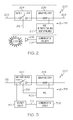
- FIG 2 is a block diagram of a control node used in a wireless embodiment of the network-based secondary electric power distribution system shown in Figure 1 ;
- FIG 3 is a block diagram of a control node used in a power line carrier embodiment of the network-based secondary electric power distribution system shown in Figure 1 ;
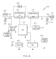
- Figure 4 is a block diagram of a wireless control node in one embodiment of the network-based secondary electric power distribution system shown in Figure 1 ;
- FIG 5 is a block diagram of a master node used in a wireless embodiment of the network-based secondary electric power distribution system shown in Figure 1 ;
- Figure 6 is a block diagram of a master node used in a power line carrier embodiment of the network-based secondary electric power distribution system shown in Figure 1 ;
- Figure 7 is a flow chart of a method for controlling a secondary electric power distribution system in accordance with one embodiment of the invention.
- the present invention generally provides a system and method for control of an electric power distribution system.
- the present invention may use a communication network for centralized monitoring and control of the supply of electricity to a load.
- the present invention may be advantageously employed in a variety of applications.
- One application is on aircraft, where electrical power is supplied to a large number of loads and it is desirable to control and monitor the current supplied to the loads from a central location.
- the present invention also may be retrofitted to existing aircraft.
- the advantages of the present invention are also particularly useful in applications where space and weight are limited because it eliminates the need for hardwire communication network to provided centralized control and monitoring functions.
- the invention uses a wireless communication network connecting control nodes with master nodes to control and monitor a solid state power controller, in contrast to prior art systems, which relied on hardwired connections for control and communication.
- the master node may remotely turn on and off the electrical power to the load, in contrast to prior art systems, which required a hardwired connection to turn on and off electrical power to the load.
- the control node may also report the state of the sensed current to the master node through the wireless communication network, in contrast to prior art systems, which relied on hardwired connections to monitor the state of sensed load currents.
- FIG. 1 shows a network-based secondary electric power distribution system (SEPDS) 100 in accordance with one embodiment of the present invention.
- the SEPDS 100 may supply electrical power through one or more types of electric power distribution subsystems.
- the embodiment in Figure 1 shows two different electric power subsystems, an alternating current (AC) power distribution subsystem 102 and a direct current (DC) power distribution subsystem 104, each of which may have one or more control nodes 106.
- the SEPDS 100 may also include one or more master nodes 108, which may be linked to the control nodes 106 through a communication system 109. Master nodes 108 may control the operation of the control nodes 106 as described in more detail below.
- Communication system 109 may either be a wireless communication network or a power line carrier communication network.
- the master nodes 108 may operate as a gateway that may use the communication system 109 to transmit and receive information, such as command data and status data, to and from a control node 106.
- the master nodes 108 may also exchange information through the same communication system 109 with any external system, which may include other intelligent systems that have access to the communication system 109 on the aircraft.
- the exact number of master nodes 108 may be depend on many factors, such as redundancy requirements, data throughput requirements, protocol requirements and other system requirements.
- the number of master nodes may typically be less than the number of control nodes 106 by a ratio of about 1 to 50.
- Each electric power subsystem 102 may comprise a source of electrical power.
- an AC power supply 110 may supply AC power through a plurality of AC power lines 112 to each control node 106.
- a DC power supply 114 may supply DC electrical power to the control nodes 106 through a plurality of DC power lines 116. Electrical power may be supplied to a plurality of loads 122 through feeder lines 123.
- Each control node 106 may include a solid state power controller (SSPC) engine 118 and a solid state switch 120.
- the SSPC engine 118 may perform control, protection and communication functions.
- SSPC engine 118 may switch on and off the power to the loads 122 through the solid state switch 120, monitor and protect the load 122 and feeder lines 123, and communicate with the master nodes 108, as described in more detail below.
- the solid state switch 120 may be any kind of solid state power device (e.g. MOSFET) that is capable of blocking and conducting electric current on command.
- Communication system 109 in the embodiment shown in Figure 1 may comprise any one of a variety of communication systems such as an ultra low power spread spectrum wireless communication system.
- the communication system 109 may utilize a meshed network topology, which may allow each control node 106 to communicate with other control nodes 106 as well as to the master nodes 108.
- the SEPDS 100 may have the features of being self-healing, by allowing some of the functions of malfunctioning control nodes 106 to be performed by other control nodes 106.
- the SEPDS 100 may have plug-play characteristics, so that individual components such as control nodes 106 and master nodes 108 may be easily replaced without replacing other components.
- FIG. 2 shows a control node 200 in accordance with one embodiment of the invention, which may use a wireless communication system 209.
- Control node 200 may comprise a SSPC 218 that communicates with the wireless communication system 109 using a communication circuit 202 having an antenna 203.
- a variety of communications standards may be used, such as the ZigBee and IEEE 802.15.4 standards.
- Control node 200 also may include a switch 204, which may receive electrical power at a first end from a DC or an AC power line 205. Switch 204 may also be connected at a second end to a sensor resistor 206. Sensor resistor 206 may comprise a low resistance value resistor as will be apparent to those skilled in the art. Line 208 may connect sensor resistor 206 to a load (not shown).
- a microcontroller (MCU) 210 may be connected to the communication circuitry 202, the switch 204 and to the sensor resistor 206.
- the MCU 210 may have two primary functions, to turn switch 204 on and off as commanded by a master node 108, and to provide over current protection.
- MCU 210 may receive an on or off command from a master node 108 through the communication circuitry 202 and respond by sending a signal to a gate 214 of switch 204 turning the switch on or off.
- the over current protection function of MCU 210 may be accomplished by sensing the current through the sense resistor 206 and determining if an over current condition exists. If the sensed current exceeds a predetermined threshold, the microcontroller unit may be programmed to open switch 204 by sending a signal through line 212 to switch gate 214 causing it to turn off switch turn off switch 204.
- FIG. 3 shows a control node 300 in accordance with another embodiment of the invention.
- control node 300 may use a power line carrier (PLC) communication system.
- PLC power line carrier
- Control node 300 may comprise a SSPC 318 that includes an switch 302 having a gate 314, a sensor resistor 304 and an MCU 306 that may be similar in function to the switch 204, sensor resistor 206 and MCU 210, respectively, shown in Figure 2 .
- MCU may be connected to the gate 314 through line 316.
- Control node 300 may include a PLC communication circuit 308 and a coupler circuit 310.
- PLC communication circuit 308 receives and transmits information between the MCU 308 and the master nodes 108.
- the coupler circuit 310 may couple the communication circuit 308 to the master nodes 108 by receiving and detecting information signals from a power line 312 through line 320. The information signal may be sent from coupler circuit 310 to communication circuit 308 through line 318.
- coupler 310 may receive information signals from the communication circuit 308 and transforms these signals into a signal that may be sent to the master nodes 108 through the power line 312.
- PLC communication circuit 308 and coupler circuit 310 may comprise standard products including transceivers available from Echelon Corporation for the LonWorks ® networking platform.
- similar LonWorks ® networking products may also be used in the master nodes 108 for receiving and transmitting information, as shown in more detail in Figure 6 .
- FIG 4 shows a block diagram of an exemplary embodiment of a control node 400 that may be used with the SEPDS 100 shown in Figure 1 .
- Control node 400 comprises a SSPC that uses wireless communications to communicate with the master nodes 108 and may perform the same functions as control node 200 shown in Figure 2 .
- Wireless communication between control node 400 and master nodes 108 may be through radio frequency signals received by an antenna 404 connected to a wireless transceiver 402, which may comprise a Freescale Semiconductor® low power wireless transceiver part number MC13192.
- the MC13192 may support the ZigBee ® and IEEE 802.15.4 standards and may generate wireless power of about 1 mw and having a communication distance of between about 10 and 50 meters.
- Wireless transceiver 402 also may be connected to an MCU 406, which may comprise a Freescale Semiconductor ® part number MC9S08GT60 8 bit microcontroller.
- MCU 406 may be programmed to perform the control node functions described above.
- MCU 406 may be is connected to a leakage clamp circuit 408, which may be used for the purpose of bypassing the leakage current of the switch 414 when the switch 414 is off. It is well recognized that some solid state power switching devices, such as MOSFETs, have a leakage current when in the off state due to the junction capacitance, which may cause a safety concern. Therefore, the leakage clamp circuit 408 is configured to be on when the switch 414 is off and to be off when the switch 414 is on, thus bypassing the leakage current so it does not reach the load 418.
- ASIC application specific integrated circuit
- ASIC 410 may provide the proper drive signal to turn the switch 414 on and off when commanded by the MCU 406.
- ASIC 410 may turn the switch 414 off when a current sense signal from a sensor resistor 412 indicates an over current condition.
- ASIC and MCU 406 may use this current sense signal to estimate the thermal energy level inside a feeder line 416 connected to a load 418. When this estimated thermal energy level exceeds a predetermined threshold, ASIC 410 may send a signal that turns the switch 414 off.
- the ASIC 414 and MCU 406 also may provide feedback signals regarding load and trip status the master nodes 108, shown in Figure 1 . Master nodes 108 may transmit this information to an aircraft load management system (not shown).
- Three transient voltage suppressors also known as "transorbs", 426, 428 and 428 and 430 may be employed to absorb transient voltages.
- a power supply 420 may receive AC electrical power from a power line 422 and BUS bar 423 and convert the AC power into a +15 volt, 50mA DC output.
- a voltage regulator 424 may convert the +15 volt output into a +5 volt, 25mA output, which may be used to provide the electrical power to the various components in the control node 400.
- Power supply 420 and voltage regulator 424 may be isolated from BUS bar 423.
- FIG. 5 shows an exemplary master node 500, which may be used as one of the master nodes 108 shown in Figure 1 , for an embodiment of the invention where the communication system 109 in Figure 1 is a wireless communication system.
- Master node 500 may include a wireless communication controller 502 in conjunction with a wireless controller 504.
- An antenna 505 may be connected to the wireless controller 504 for transmitting and receiving radio frequency signals to and from one or more of the control nodes 106.
- additional redundant wireless controllers 504 may also be connected to the communication controller 502.
- a total of four wireless controllers may be used, although other numbers of wireless controllers may be used depending on the particular needs of the SEPDS 100.
- wireless communication controller 502 comprises a low power wireless communication controller such as the Freescale Semiconductor ® MPC8250, and the wireless controller 504 may be a Freescale Semiconductor ® MC13192, such as the wireless transceiver 402 described above and shown in Figure 4 . Both the communication controller 502 and the wireless controller 504 may implement the IEEE 802.15.4 standard. Communication controller 502 may be coupled to an avionics full-duplex switched Ethernet (AFDX) interface 506. AFDX defines a low-level network and protocol to communicate between avionics devices in an aircraft. The AFDX interface may receive and transmit information to and from an AFDX network (not shown).
- AFDX avionics full-duplex switched Ethernet
- the communication controller 502 may be configured in a meshed network topology, utilizing the ZigBee ® protocol.
- a meshed network topology may improve network reliability since each control node will have the ability to relay information to its adjacent control nodes and to the master nodes so that the system may be self-healing and plug-play.
- FIG 6 shows a master node 600 that is adapted to be used with a power line carrier communication system.
- Master node 600 may be compatible with control node 300 shown in Figure 3 .
- a coupler circuit 602 may receive information from a carrier signal on a power line 604. This signal may be detected by the coupler circuit 602 and sent to a communication controller 606, which may be similar to communication circuit 308 shown in Figure 3 .
- An AFDX interface 608 may receive the information from the communication controller 606 in a receive mode and send it to an AFDX interface 608.
- the AFDX interface 608 may send received information to other systems on the aircraft through an AFDX network (not shown).
- commands may be sent from a system on an aircraft through an AFDX network (not shown) to the AFDX interface 608. These commands may be sent by the AFDX interface 608 to the communication controller 606, which in turn may convert the information into a signal that is applied to a carrier signal on the power line 604. As with the Communication controller 502 in Figure 5 , the communication controller 606 may be implemented in a meshed network such as the ZigBee ® protocol.
- FIG. 7 shows a method 700 for controlling an electric power distribution system in accordance with another embodiment of the invention.
- electrical power may be supplied from a source (e.g. a generator 110 or a battery 114) to a load, such as load 122.
- a master node 108 may send a command to a control node 106 to either open or close a switch 120 120 connecting the load 122 to the source, 110 or 114, of electrical power.
- This command may be sent to the control node 106 through either a wireless, a power line carrier or other communication system 109.
- step 706 the control node 106 may receive the command and determines, in step 710 if it is an open command or not. If the received command is an open command as determined in step 710, step 712 may open the switch 126, thereby disconnecting the load 122 from the source, 110 or 114, of electrical power. The process 700 then may return to step 704 until another command is sent by the master node 108. If step 710 determined that the command was not an open command, then the only other possibility is that it is a close command and step 714 may close the switch 120 thereby connecting the load 122 to the source, 110 or 114, of electrical power.
Landscapes
- Engineering & Computer Science (AREA)
- Power Engineering (AREA)
- Remote Monitoring And Control Of Power-Distribution Networks (AREA)
Abstract
A system (100) and method for control of an electric power distribution system is provided, which uses a communication network (109) for centralized monitoring and control of the supply of electricity to a load (122). In one embodiment, the invention may use a wireless communication system (109) connecting control nodes (106) and master nodes (108) to control and monitor a solid state power controller (118). As a result, the master node (108) may remotely turn on and off the electrical power to the load (122). Also the control node (106) may sense the current being supplied to the load (122) and may turn off the supply of electrical power in the event of an over current situation. The control node (106) may also report the state of the sensed current to the master node (108). In another embodiment, the communication system (109) may be a power line carrier network.
Description
- The present invention relates to secondary electrical power distribution systems and more particularly to secondary electrical power distribution systems having network-controlled solid state power controllers.
- In a conventional secondary electrical power distribution system (SEPDS), such as those used on aircraft, electric power is distributed to electrical loads through electro-mechanical relays in combination with circuit breakers. Due to increasing demands in avionic systems, there is a need for improvements in SEPDSs in the areas of reliability, size, weight and cost, which cannot always be met by electro-mechanical systems.
- As a result, SEPDSs which use solid state power controller (SSPC) technology as an electric management center have been introduced. SSPCs offer a number of advantages over electro-mechanical relays and circuit breakers. In such systems, several SSPC channels are usually located on one circuit card assembly (CCA) and several of these CCAs are then installed in one line replaceable unit (LRU). The control of the SSPC channels is usually through a centralized gateway designated for the LRU via a main data bus. The local control circuitry on each CCA interfaces to the gateway via an internal data bus inside the LRU.
- SEPDSs that utilize SSPC technology achieve some of the above-discussed needed improvements over electro-mechanical technology. Also, SSPC provides system intelligence, remote control, and convenient maintenance. However, there is still a need for improvements to SSPC-based SEPDS. Centralized control can introduce additional wiring and hardware, increase power consumption, and add to the material cost and to the system weight as compared to some electromechanical systems. The increased complexity of SSPC-based SEPDSs also can create reliability issues. Dependency among various SSPC channels means that the failure of one SSPC channel can affect other SSPC channels. There is also a need to reduce thermal dissipation in SSPC technology-based SEPDs, where, for example, several SSPC channels may be clustered in one CCA, and several CCAs, may be clustered in one envelope to share a common backplane, power supply and data bus. Also, SSPC-based SEPDs can not always be easily retrofitted into older systems that have electro-mechanical SEPDS.
- As can be seen, there is a need for an SSPC-based SEPD which minimizes the hardware, power consumption, thermal dissipation, weight, size, and cost. There is a further need for an SSPC-based SEPD with improved reliability over existing systems. Still further there is a need for an SSPC-based SEPD that is easily retrofitted into an existing electro-mechanical SEPD system.
- In one aspect of the present invention, an electric power distribution system comprises: at least one source of electrical power; at least one load connected by a conductor to the at least one source of electrical power; a switch disposed across the conductor, the switch connecting the load to the at least one source of electrical power when in a closed state and disconnecting the load from the at least one source of electrical power when in an open state; at least one master node; and a wireless communication network carrying commands from the master node to the switch to open the switch and commands to close the switch.
- In another aspect of the present invention a system for sensing electrical power transferred to a load comprises: a load; a source of electrical power connected by a conductor to the load; a sensor connected to the conductor, the sensor detecting a current passing through the conductor; a microcontroller connected to the sensor; and a wireless communication network coupled to the sensor and to the microcontroller carrying information regarding the current detected by the sensor.
- In a further aspect of the present invention, a method for controlling an electric power distribution system comprises: transferring electrical power from a source to a load through a conductor, the conductor having a switch connected to a control node; sending a plurality of commands from a master node to the control node through a powerline carrier communication network, the plurality of commands including commands to open the switch and commands to close the switch; receiving the plurality of commands in the control node through the powerline carrier communication network; sending a plurality of signals to the switch from the control node, a first type of the plurality of signals causing the switch to open and a second type of the plurality of signals causing the switch to close; and opening the switch in response to the command to open the switch and closing the switch in response to the command to close the switch.
- These and other features, aspects and advantages of the present invention will become better understood with reference to the following drawings, description and claims.
-
Figure 1 is a block diagram of a network-based secondary electric power distribution system in accordance with one embodiment of the invention; -
Figure 2 is a block diagram of a control node used in a wireless embodiment of the network-based secondary electric power distribution system shown inFigure 1 ; -
Figure 3 is a block diagram of a control node used in a power line carrier embodiment of the network-based secondary electric power distribution system shown inFigure 1 ; -
Figure 4 is a block diagram of a wireless control node in one embodiment of the network-based secondary electric power distribution system shown inFigure 1 ; -
Figure 5 is a block diagram of a master node used in a wireless embodiment of the network-based secondary electric power distribution system shown inFigure 1 ; -
Figure 6 is a block diagram of a master node used in a power line carrier embodiment of the network-based secondary electric power distribution system shown inFigure 1 ; and -
Figure 7 is a flow chart of a method for controlling a secondary electric power distribution system in accordance with one embodiment of the invention. - The following detailed description is of the best currently contemplated modes of carrying out the invention. The description is not to be taken in a limiting sense, but is made merely for the purpose of illustrating the general principles of the invention, since the scope of the invention is best defined by the appended claims.
- The present invention generally provides a system and method for control of an electric power distribution system. The present invention may use a communication network for centralized monitoring and control of the supply of electricity to a load. The present invention may be advantageously employed in a variety of applications. One application is on aircraft, where electrical power is supplied to a large number of loads and it is desirable to control and monitor the current supplied to the loads from a central location. The present invention also may be retrofitted to existing aircraft. The advantages of the present invention are also particularly useful in applications where space and weight are limited because it eliminates the need for hardwire communication network to provided centralized control and monitoring functions.
- In particular, in one embodiment, the invention uses a wireless communication network connecting control nodes with master nodes to control and monitor a solid state power controller, in contrast to prior art systems, which relied on hardwired connections for control and communication. In this way, the master node may remotely turn on and off the electrical power to the load, in contrast to prior art systems, which required a hardwired connection to turn on and off electrical power to the load. The control node may also report the state of the sensed current to the master node through the wireless communication network, in contrast to prior art systems, which relied on hardwired connections to monitor the state of sensed load currents.
-
Figure 1 shows a network-based secondary electric power distribution system (SEPDS) 100 in accordance with one embodiment of the present invention. The SEPDS 100 may supply electrical power through one or more types of electric power distribution subsystems. The embodiment inFigure 1 shows two different electric power subsystems, an alternating current (AC) power distribution subsystem 102 and a direct current (DC) power distribution subsystem 104, each of which may have one ormore control nodes 106. The SEPDS 100 may also include one ormore master nodes 108, which may be linked to thecontrol nodes 106 through acommunication system 109.Master nodes 108 may control the operation of thecontrol nodes 106 as described in more detail below.Communication system 109 may either be a wireless communication network or a power line carrier communication network. - In general, the
master nodes 108 may operate as a gateway that may use thecommunication system 109 to transmit and receive information, such as command data and status data, to and from acontrol node 106. Themaster nodes 108 may also exchange information through thesame communication system 109 with any external system, which may include other intelligent systems that have access to thecommunication system 109 on the aircraft. The exact number ofmaster nodes 108 may be depend on many factors, such as redundancy requirements, data throughput requirements, protocol requirements and other system requirements. The number of master nodes may typically be less than the number ofcontrol nodes 106 by a ratio of about 1 to 50. - Each electric power subsystem 102 may comprise a source of electrical power. In the case of electrical power subsystem 102, an
AC power supply 110 may supply AC power through a plurality ofAC power lines 112 to eachcontrol node 106. In the case of electrical power subsystem 104, aDC power supply 114 may supply DC electrical power to thecontrol nodes 106 through a plurality ofDC power lines 116. Electrical power may be supplied to a plurality ofloads 122 throughfeeder lines 123. - Each
control node 106 may include a solid state power controller (SSPC)engine 118 and asolid state switch 120. The SSPCengine 118 may perform control, protection and communication functions. In particular, SSPCengine 118 may switch on and off the power to theloads 122 through thesolid state switch 120, monitor and protect theload 122 andfeeder lines 123, and communicate with themaster nodes 108, as described in more detail below. Thesolid state switch 120 may be any kind of solid state power device (e.g. MOSFET) that is capable of blocking and conducting electric current on command. -
Communication system 109 in the embodiment shown inFigure 1 may comprise any one of a variety of communication systems such as an ultra low power spread spectrum wireless communication system. Thecommunication system 109 may utilize a meshed network topology, which may allow eachcontrol node 106 to communicate withother control nodes 106 as well as to themaster nodes 108. As a result, theSEPDS 100 may have the features of being self-healing, by allowing some of the functions of malfunctioningcontrol nodes 106 to be performed byother control nodes 106. Also, theSEPDS 100 may have plug-play characteristics, so that individual components such ascontrol nodes 106 andmaster nodes 108 may be easily replaced without replacing other components. -
Figure 2 shows acontrol node 200 in accordance with one embodiment of the invention, which may use awireless communication system 209.Control node 200 may comprise aSSPC 218 that communicates with thewireless communication system 109 using acommunication circuit 202 having anantenna 203. A variety of communications standards may be used, such as the ZigBee and IEEE 802.15.4 standards. -
Control node 200 also may include aswitch 204, which may receive electrical power at a first end from a DC or anAC power line 205.Switch 204 may also be connected at a second end to asensor resistor 206.Sensor resistor 206 may comprise a low resistance value resistor as will be apparent to those skilled in the art.Line 208 may connectsensor resistor 206 to a load (not shown). - A microcontroller (MCU) 210 may be connected to the
communication circuitry 202, theswitch 204 and to thesensor resistor 206. TheMCU 210 may have two primary functions, to turnswitch 204 on and off as commanded by amaster node 108, and to provide over current protection. For the on and off function,MCU 210 may receive an on or off command from amaster node 108 through thecommunication circuitry 202 and respond by sending a signal to agate 214 ofswitch 204 turning the switch on or off. - The over current protection function of
MCU 210 may be accomplished by sensing the current through thesense resistor 206 and determining if an over current condition exists. If the sensed current exceeds a predetermined threshold, the microcontroller unit may be programmed to openswitch 204 by sending a signal throughline 212 to switchgate 214 causing it to turn off switch turn offswitch 204. -
Figure 3 shows acontrol node 300 in accordance with another embodiment of the invention. Instead of using a wireless communication system as was the case withcontrol node 200,control node 300 may use a power line carrier (PLC) communication system.Control node 300 may comprise aSSPC 318 that includes answitch 302 having agate 314, asensor resistor 304 and anMCU 306 that may be similar in function to theswitch 204,sensor resistor 206 andMCU 210, respectively, shown inFigure 2 . MCU may be connected to thegate 314 throughline 316. -
Control node 300 may include aPLC communication circuit 308 and acoupler circuit 310.PLC communication circuit 308 receives and transmits information between theMCU 308 and themaster nodes 108. In particular, thecoupler circuit 310 may couple thecommunication circuit 308 to themaster nodes 108 by receiving and detecting information signals from apower line 312 through line 320. The information signal may be sent fromcoupler circuit 310 tocommunication circuit 308 throughline 318. Also, in the reverse direction,coupler 310 may receive information signals from thecommunication circuit 308 and transforms these signals into a signal that may be sent to themaster nodes 108 through thepower line 312. In one embodiment of the invention,PLC communication circuit 308 andcoupler circuit 310 may comprise standard products including transceivers available from Echelon Corporation for the LonWorks® networking platform. In this power line carrier embodiment, similar LonWorks® networking products may also be used in themaster nodes 108 for receiving and transmitting information, as shown in more detail inFigure 6 . -
Figure 4 shows a block diagram of an exemplary embodiment of acontrol node 400 that may be used with theSEPDS 100 shown inFigure 1 .Control node 400 comprises a SSPC that uses wireless communications to communicate with themaster nodes 108 and may perform the same functions ascontrol node 200 shown inFigure 2 . Wireless communication betweencontrol node 400 andmaster nodes 108 may be through radio frequency signals received by anantenna 404 connected to awireless transceiver 402, which may comprise a Freescale Semiconductor® low power wireless transceiver part number MC13192. The MC13192 may support the ZigBee® and IEEE 802.15.4 standards and may generate wireless power of about 1 mw and having a communication distance of between about 10 and 50 meters. -
Wireless transceiver 402 also may be connected to anMCU 406, which may comprise a Freescale Semiconductor® part number MC9S08GT60 8 bit microcontroller.MCU 406 may be programmed to perform the control node functions described above.MCU 406 may be is connected to aleakage clamp circuit 408, which may be used for the purpose of bypassing the leakage current of theswitch 414 when theswitch 414 is off. It is well recognized that some solid state power switching devices, such as MOSFETs, have a leakage current when in the off state due to the junction capacitance, which may cause a safety concern. Therefore, theleakage clamp circuit 408 is configured to be on when theswitch 414 is off and to be off when theswitch 414 is on, thus bypassing the leakage current so it does not reach theload 418. -
MCU 406 also may be connected to an application specific integrated circuit (ASIC) 410. During normal operating conditions,ASIC 410 may provide the proper drive signal to turn theswitch 414 on and off when commanded by theMCU 406. During overcurrent conditions ASIC 410 may turn theswitch 414 off when a current sense signal from asensor resistor 412 indicates an over current condition. In particular, ASIC andMCU 406 may use this current sense signal to estimate the thermal energy level inside afeeder line 416 connected to aload 418. When this estimated thermal energy level exceeds a predetermined threshold,ASIC 410 may send a signal that turns theswitch 414 off. TheASIC 414 andMCU 406 also may provide feedback signals regarding load and trip status themaster nodes 108, shown inFigure 1 .Master nodes 108 may transmit this information to an aircraft load management system (not shown). Three transient voltage suppressors, also known as "transorbs", 426, 428 and 428 and 430 may be employed to absorb transient voltages. - In one embodiment of the invention, a
power supply 420 may receive AC electrical power from a power line 422 andBUS bar 423 and convert the AC power into a +15 volt, 50mA DC output. Avoltage regulator 424 may convert the +15 volt output into a +5 volt, 25mA output, which may be used to provide the electrical power to the various components in thecontrol node 400.Power supply 420 andvoltage regulator 424 may be isolated fromBUS bar 423. -
Figure 5 shows anexemplary master node 500, which may be used as one of themaster nodes 108 shown inFigure 1 , for an embodiment of the invention where thecommunication system 109 inFigure 1 is a wireless communication system.Master node 500 may include awireless communication controller 502 in conjunction with awireless controller 504. Anantenna 505 may be connected to thewireless controller 504 for transmitting and receiving radio frequency signals to and from one or more of thecontrol nodes 106. For improved system reliability, additionalredundant wireless controllers 504 may also be connected to thecommunication controller 502. As shown inFigure 5 , a total of four wireless controllers may be used, although other numbers of wireless controllers may be used depending on the particular needs of theSEPDS 100. - In one embodiment of the invention,
wireless communication controller 502 comprises a low power wireless communication controller such as the Freescale Semiconductor® MPC8250, and thewireless controller 504 may be a Freescale Semiconductor® MC13192, such as thewireless transceiver 402 described above and shown inFigure 4 . Both thecommunication controller 502 and thewireless controller 504 may implement the IEEE 802.15.4 standard.Communication controller 502 may be coupled to an avionics full-duplex switched Ethernet (AFDX)interface 506. AFDX defines a low-level network and protocol to communicate between avionics devices in an aircraft. The AFDX interface may receive and transmit information to and from an AFDX network (not shown). - Furthermore, the
communication controller 502 may be configured in a meshed network topology, utilizing the ZigBee® protocol. A meshed network topology, may improve network reliability since each control node will have the ability to relay information to its adjacent control nodes and to the master nodes so that the system may be self-healing and plug-play. -
Figure 6 shows amaster node 600 that is adapted to be used with a power line carrier communication system.Master node 600 may be compatible withcontrol node 300 shown inFigure 3 . Acoupler circuit 602 may receive information from a carrier signal on a power line 604. This signal may be detected by thecoupler circuit 602 and sent to acommunication controller 606, which may be similar tocommunication circuit 308 shown inFigure 3 . AnAFDX interface 608 may receive the information from thecommunication controller 606 in a receive mode and send it to anAFDX interface 608. TheAFDX interface 608 may send received information to other systems on the aircraft through an AFDX network (not shown). - In a transmit mode, in accordance with one embodiment of the invention, commands may be sent from a system on an aircraft through an AFDX network (not shown) to the
AFDX interface 608. These commands may be sent by theAFDX interface 608 to thecommunication controller 606, which in turn may convert the information into a signal that is applied to a carrier signal on the power line 604. As with theCommunication controller 502 inFigure 5 , thecommunication controller 606 may be implemented in a meshed network such as the ZigBee® protocol. -
Figure 7 shows amethod 700 for controlling an electric power distribution system in accordance with another embodiment of the invention. Instep 702 electrical power may be supplied from a source (e.g. agenerator 110 or a battery 114) to a load, such asload 122. In step 704 amaster node 108 may send a command to acontrol node 106 to either open or close aswitch 120 120 connecting theload 122 to the source, 110 or 114, of electrical power. This command may be sent to thecontrol node 106 through either a wireless, a power line carrier orother communication system 109. - In
step 706 thecontrol node 106 may receive the command and determines, instep 710 if it is an open command or not. If the received command is an open command as determined instep 710,step 712 may open the switch 126, thereby disconnecting theload 122 from the source, 110 or 114, of electrical power. Theprocess 700 then may return to step 704 until another command is sent by themaster node 108. Ifstep 710 determined that the command was not an open command, then the only other possibility is that it is a close command and step 714 may close theswitch 120 thereby connecting theload 122 to the source, 110 or 114, of electrical power. - It should be understood, of course, that the foregoing relates to exemplary embodiments of the invention and that modifications may be made without departing from the spirit and scope of the invention as set forth in the following claims.
Claims (10)
- An electric power distribution system (100) comprising:at least one source (110) of electrical power;at least one load (122) connected by a conductor (123) to said at least one source of electrical power (110);a switch (120) disposed across said conductor (123), said switch (120) connecting said load (122) to said at least one source of electrical power (110) when in a closed state and disconnecting said load (122) from said at least one source of electrical power (110) when in an open state;at least one master node (108); anda wireless communication network (109) carrying commands from said master node (108) to said switch (120) to open said switch (120) and commands to close said switch (120).
- The electric power distribution system of (100) claim 1 further comprising:a control node (106) connected to said switch (120) and controlling said state of said switch (120); andwherein said wireless communication network carries information between said master node (108) and said control node (106), said information including said commands from said master node (108) to said control node (106) to open said switch (120) and commands from said master node (108) to said control node (106) to close said switch (120).
- The electric power distribution system (100) of claim 2 further comprising:a sensor (206) connected to said conductor (123) and to said control node (106), wherein said sensor (206) detects a current passing through said conductor (123), wherein said control node (106) opens said switch (120) when said current detected by said sensor (206) is above a predetermined threshold.
- The electric power distribution system (100) of claim 3 wherein said information carried by said wireless communication network (109) includes information regarding said current detected by said sensor (206).
- The electric power distribution system (100) of claim 2 further comprising:an additional load (122) connected to said source of electrical power (110) through an additional conductor (123);an additional switch (120) disposed across said additional conductor (123), said additional switch (120) connecting said load (122) to said source of electrical power (110) when in a closed state and disconnecting said load (122) from said source of electrical power (110) when in an open state;an additional control node (106) connected to said additional switch (120), said additional control node (106) controlling said state of said additional switch (120); andsaid wireless communication network (109) carrying information between said master node (108) and said additional control node (106).
- The electric power distribution system (100) of claim 5 further comprising an additional master node (108) connected by said communication system (109) to said additional control node (106).
- The electric power distribution system (100) of claim 1 further comprising an avionics full-duplex switched Ethernet (AFDX) system (608) in an aircraft connected to said master node (108), said AFDX system (608) receiving commands from said aircraft to open and close said switch (120). (120).
- The electric power distribution system (100) of claim 2 further comprising:an additional source of electrical power (114);an additional load (122) connected by an additional conductor (123) to said additional source of electrical power (114);an additional switch (120) disposed across said additional conductor (123), said additional switch (120) connecting said additional load (122) to said additional source of electrical power (114) when in a closed state and disconnecting said additional load (122) from said additional source of electrical power (114) when in an open state;an additional control node (106) connected to said additional switch (120) and controlling said state of said additional switch (120); andsaid wireless communication network (109) carrying information between said master node (108) and said additional control node (106), said information including commands from said master node (108) to said additional control node (106) to open and close said additional switch (120).
- The electric power distribution system (100) of claim 8 wherein said source of electrical power (110) and said additional source of electrical power (114) each provide electrical power of a type selected from the following: alternating current electrical power and direct current electrical power.
- The electric power distribution system (100) of claim 1 wherein said wireless communication network (109) is a radio frequency communication network.
Applications Claiming Priority (1)
| Application Number | Priority Date | Filing Date | Title |
|---|---|---|---|
| US11/760,579 US7598625B2 (en) | 2007-06-08 | 2007-06-08 | Network-based aircraft secondary electric power distribution system |
Publications (1)
| Publication Number | Publication Date |
|---|---|
| EP2001104A2 true EP2001104A2 (en) | 2008-12-10 |
Family
ID=39743835
Family Applications (1)
| Application Number | Title | Priority Date | Filing Date |
|---|---|---|---|
| EP20080157699 Withdrawn EP2001104A2 (en) | 2007-06-08 | 2008-06-05 | Network-based aircraft secondary electric power distribution system |
Country Status (2)
| Country | Link |
|---|---|
| US (1) | US7598625B2 (en) |
| EP (1) | EP2001104A2 (en) |
Cited By (36)
| Publication number | Priority date | Publication date | Assignee | Title |
|---|---|---|---|---|
| EP2199201A1 (en) * | 2008-12-22 | 2010-06-23 | Messier-Bugatti | Power-distribution architecture for distributing power to electromechanical actuators of an aircraft |
| CN102355051A (en) * | 2011-07-21 | 2012-02-15 | 常州森隆电力科技有限公司 | On-line monitoring system of breaker and on-line monitoring method thereof |
| CN102377187A (en) * | 2011-10-19 | 2012-03-14 | 镇江博扬电气科技有限公司 | Reactive compensation system on remote monitoring post |
| CN102638097A (en) * | 2012-03-26 | 2012-08-15 | 天津市三源电力设备制造有限公司 | Remote concentrated measurement and control system for distribution network |
| CN102710015A (en) * | 2012-05-25 | 2012-10-03 | 清华大学 | Intelligent terminal device adaptive to intelligent transformer substation |
| CN102780271A (en) * | 2012-08-23 | 2012-11-14 | 健雄职业技术学院 | 3G smart monitoring terminal for connection of photovoltaic micro-network power generation system to power grid |
| CN102931726A (en) * | 2012-10-22 | 2013-02-13 | 深圳供电局有限公司 | Power supply system is protected to main and distribution network integration |
| CN103023151A (en) * | 2012-12-19 | 2013-04-03 | 广东电网公司电力科学研究院 | Intelligent power consumption communication platform system |
| CN103259336A (en) * | 2013-04-17 | 2013-08-21 | 无锡市崇安区科技创业服务中心 | High-voltage fault monitoring system based on internet of things technology |
| CN103354388A (en) * | 2013-06-19 | 2013-10-16 | 国家电网公司 | Multi-service linked electric power operation instruction issuing method |
| ES2400152R1 (en) * | 2011-09-15 | 2013-10-24 | Eads Constr Aeronauticas Sa | AN ELECTRICAL SYSTEM OF AN AIRCRAFT. |
| CN103560588A (en) * | 2013-11-18 | 2014-02-05 | 国家电网公司 | Inquiring and monitoring method and device for power dispatching |
| CN103698584A (en) * | 2014-01-08 | 2014-04-02 | 广州思泰信息技术有限公司 | Power distribution network overhead line three-phase current sampling synchronization method |
| FR2997507A1 (en) * | 2012-10-29 | 2014-05-02 | Labinal | SYSTEM AND METHOD FOR MONITORING A CURRENT RETURN NETWORK OF AN AIRCRAFT |
| CN104052152A (en) * | 2014-05-26 | 2014-09-17 | 北京航天发射技术研究所 | Intelligent power supply and distribution unit |
| EP2690785A3 (en) * | 2012-07-26 | 2014-12-31 | General Electric Company | Method, system and apparatus for galvanic isolation of gate-controlled devices |
| CN104333132A (en) * | 2014-10-23 | 2015-02-04 | 盐城工学院 | Household power distribution method, household power distribution system and distribution box |
| EP2838173A1 (en) * | 2013-08-09 | 2015-02-18 | The Boeing Company | Advanced energy monitoring and control in a complex system |
| EP2945244A1 (en) * | 2014-05-15 | 2015-11-18 | Airbus Operations GmbH | Power and data distribution module and method for power and data distribution in an airborne vehicle |
| CN105242152A (en) * | 2015-11-11 | 2016-01-13 | 成都府河电力自动化成套设备有限责任公司 | Intelligent switching value isolated acquisition unit |
| CN105262223A (en) * | 2015-11-05 | 2016-01-20 | 国家电网公司 | Microcomputer protection abnormity processing auxiliary device |
| CN105305393A (en) * | 2015-10-21 | 2016-02-03 | 珠海许继芝电网自动化有限公司 | Distribution network emergency repair commanding system and method based on marketing and distribution communication |
| CN105445617A (en) * | 2015-11-18 | 2016-03-30 | 国网天津市电力公司 | Automatic studying and determination method of power distribution fault |
| CN106026205A (en) * | 2016-06-30 | 2016-10-12 | 温州大学 | Parallel power supply system optimization control method based on efficiency and current-sharing performance area sum maximization |
| CN106026204A (en) * | 2016-06-30 | 2016-10-12 | 温州大学 | Parallel power supply system current-sharing performance evaluation method based on current-sharing deviation expectation matrix 1 norm |
| CN106094523A (en) * | 2016-06-30 | 2016-11-09 | 温州大学 | Based on efficiency and current-sharing index area and maximum parallel operation system optimized control method |
| CN106099998A (en) * | 2016-06-30 | 2016-11-09 | 温州大学 | Parallel operation system current-sharing method of evaluating performance based on current-sharing standard deviation matrix ∞ norm |
| CN106130001A (en) * | 2016-06-30 | 2016-11-16 | 温州大学 | The parallel operation system power supply module number gray discrete system method that the expectation of a kind of current-sharing deviation is minimum |
| CN106160021A (en) * | 2016-06-30 | 2016-11-23 | 温州大学 | Parallel operation system optimal point based on efficiency and current-sharing standard deviation weighted sum matrix determines method |
| CN106160019A (en) * | 2016-06-30 | 2016-11-23 | 温州大学 | Parallel operation system optimal point based on efficiency and current-sharing index area and maximum determines method |
| CN106160011A (en) * | 2016-06-30 | 2016-11-23 | 温州大学 | Parallel operation system module number controlling method based on efficiency and current-sharing index golden section |
| CN106300680A (en) * | 2016-10-12 | 2017-01-04 | 安徽徽云信息科技有限公司 | A kind of computer based electric power monitoring system |
| CN106532934A (en) * | 2016-10-18 | 2017-03-22 | 兰州海红技术股份有限公司 | Alternating current row cabinet intelligent monitoring system |
| CN106532962A (en) * | 2016-12-26 | 2017-03-22 | 中国能源建设集团广东省电力设计研究院有限公司 | Centralized control method, device and system for multi-end flexible direct current converter stations |
| WO2018065043A1 (en) * | 2016-10-05 | 2018-04-12 | Jmp Ingenieros S.L. | Modular power bus architecture and method for optimum power management of distributed power sources and drains |
| CN109586258A (en) * | 2018-12-10 | 2019-04-05 | 国家电网有限公司 | A kind of the control and protective switch wireless communication apparatus and method of power distribution network |
Families Citing this family (44)
| Publication number | Priority date | Publication date | Assignee | Title |
|---|---|---|---|---|
| TW200834629A (en) * | 2007-02-05 | 2008-08-16 | Jjplus Corp | Remote power control method |
| US7634329B2 (en) * | 2007-03-05 | 2009-12-15 | Honeywell International Inc. | Intelligent aircraft secondary power distribution system that facilitates condition based maintenance |
| US8050806B2 (en) * | 2007-03-21 | 2011-11-01 | Honeywell International Inc. | Ground fault interruption using DSP based SSPC module |
| US8248984B2 (en) * | 2007-06-20 | 2012-08-21 | I Squared Llc | System and method for interfacing devices |
| US7977959B2 (en) * | 2007-09-27 | 2011-07-12 | Formfactor, Inc. | Method and apparatus for testing devices using serially controlled intelligent switches |
| US20090200864A1 (en) * | 2008-02-12 | 2009-08-13 | Josef Maier | Chip on bus bar |
| DE102009001081B3 (en) * | 2009-02-23 | 2010-04-22 | Airbus Deutschland Gmbh | Device for transmitting data e.g. control data, and energy over e.g. network nodes, of Ethernet network in e.g. passenger aircraft, has supply unit supplying data-voltage signal to receiving line with supply voltage signals |
| US7898115B2 (en) * | 2009-02-27 | 2011-03-01 | Meltzner Jamie H | Power supply switch |
| WO2010144465A1 (en) * | 2009-06-08 | 2010-12-16 | Raritan Americas, Inc. | Wireless power distribution system and device |
| EP2446517B1 (en) | 2009-06-26 | 2020-01-22 | Koninklijke Philips N.V. | Power distribution apparatus |
| US8275494B1 (en) | 2009-12-31 | 2012-09-25 | Michael Roth | System, apparatus and method for controlling an aircraft |
| EP2442425B1 (en) * | 2010-10-15 | 2016-03-30 | Airbus Defence and Space SA | Electrical power control system for a vehicle. |
| US9143029B2 (en) | 2011-12-15 | 2015-09-22 | General Electric Company | System and method for power distribution |
| US8836338B2 (en) | 2011-12-16 | 2014-09-16 | Ge Aviation Systems Limited | Switching circuits and methods of testing thereof |
| US9829526B2 (en) * | 2012-02-21 | 2017-11-28 | Texas Instruments Incorporated | Transmission line pulsing |
| US20130241284A1 (en) * | 2012-03-14 | 2013-09-19 | Transistor Devices, Inc. . d/b/a TDI Power | Load Distribution System and Power Management System and Method |
| US9896045B2 (en) * | 2012-03-15 | 2018-02-20 | Carling Technologies, Inc. | Touch activated, wireless switches |
| US20140175877A1 (en) * | 2012-08-13 | 2014-06-26 | William Baker | Building Power Management System |
| CN103913619B (en) * | 2012-12-30 | 2016-05-18 | 航天信息股份有限公司 | Based on the current monitoring method of wireless sensor network |
| US9240685B2 (en) * | 2013-01-21 | 2016-01-19 | Hamilton Sundstrand Corporation | Reconfigurable matrix-based power distribution architecture |
| WO2014152429A1 (en) * | 2013-03-15 | 2014-09-25 | Dominion Resources, Inc. | Management of energy on electric power systems |
| US9561761B2 (en) * | 2013-10-11 | 2017-02-07 | The Boeing Company | Modular equipment center zonal standalone power system control architecture |
| CN105629118A (en) * | 2014-11-04 | 2016-06-01 | 国家电网公司 | Outdoor electric power line wireless monitoring system |
| CN105186689B (en) * | 2015-08-27 | 2018-04-20 | 深圳市信锐网科技术有限公司 | Method and system, the digitlization end electric power access device of electric power centralized management |
| GB201522651D0 (en) | 2015-12-22 | 2016-02-03 | Rolls Royce Controls & Data Services Ltd | Solid state power control |
| US10048997B2 (en) * | 2016-05-04 | 2018-08-14 | Hamilton Sundstrand Corporation | Single event latch up mitigation in solid state power controllers |
| US10518898B2 (en) | 2016-05-13 | 2019-12-31 | Goodrich Corporation | Communication system and method for an aircraft cargo/freight handling system |
| US10980638B2 (en) | 2017-08-04 | 2021-04-20 | Boston Scientific Scimed, Inc. | Penile implant |
| CN107907752B (en) * | 2017-09-22 | 2020-01-24 | 国网上海市电力公司 | Method for positioning regional direct current ground potential fluctuation source |
| CN107621585A (en) * | 2017-10-12 | 2018-01-23 | 国家电网公司 | A kind of strong electromagnetic transient signal measuring system and method based on radio communication |
| US11139992B1 (en) * | 2017-10-30 | 2021-10-05 | Rockwell Collins, Inc. | Systems and methods for remotely powered data concentrators for distributed IMA system |
| PL3579376T3 (en) | 2018-06-08 | 2020-08-10 | Ovh | Methods and systems for identifying a connection path between a power source and a load |
| US10998935B2 (en) * | 2019-02-20 | 2021-05-04 | Honeywell Limited | Secondary electric power distribution system (SEPDS) to facilitate aircraft connectivity |
| US11140003B2 (en) | 2019-11-22 | 2021-10-05 | Hamilton Sundstrand Corporation | Main feeders as comms lines |
| US11157057B1 (en) * | 2020-05-28 | 2021-10-26 | Ovh | Systems and methods for electric systems monitoring and/or failure detection |
| US11832414B2 (en) * | 2020-08-05 | 2023-11-28 | Dell Products L.P. | Power distribution powerline networking management system |
| CN112114554B (en) * | 2020-09-11 | 2024-07-30 | 智慧式有限公司 | Wireless control system and method for power supply on-off of power equipment |
| GB2601129B (en) | 2020-11-18 | 2023-05-31 | Ge Aviat Systems Ltd | System and method for operating a power distribution system |
| WO2022192698A1 (en) | 2021-03-12 | 2022-09-15 | Essex Industries, Inc., | Rocker switch |
| US11688568B2 (en) | 2021-03-15 | 2023-06-27 | Essex Industries, Inc. | Five-position switch |
| US11489553B1 (en) | 2021-04-13 | 2022-11-01 | Ovh | System and method for identifying a connection between a power distribution unit and an electric device |
| US11677234B2 (en) * | 2021-08-20 | 2023-06-13 | Hamilton Sundstrand Corporation | Power input source detection in aircraft LRU |
| CN115549195B (en) * | 2022-10-14 | 2023-04-07 | 哈尔滨工业大学 | An aircraft distributed remote power distribution system and its working method |
| CN117439277B (en) * | 2023-12-21 | 2024-04-09 | 天津航空机电有限公司 | A communication network structure and communication method for a secondary power distribution system |
Family Cites Families (7)
| Publication number | Priority date | Publication date | Assignee | Title |
|---|---|---|---|---|
| US5576700A (en) * | 1992-08-26 | 1996-11-19 | Scientific-Atlanta | Apparatus and method for controlling an electrical load and monitoring control operations and the electrical load |
| US5598039A (en) * | 1993-03-15 | 1997-01-28 | Touchstone Patent Trust | Method and apparatus for sensing state of electric power flow through a master circuit and producing remote control of a slave circuit |
| US5752047A (en) | 1995-08-11 | 1998-05-12 | Mcdonnell Douglas Corporation | Modular solid state power controller with microcontroller |
| GB9614590D0 (en) * | 1996-07-11 | 1996-09-04 | Smiths Industries Plc | Electrical apparatus |
| US7007179B2 (en) | 2001-02-08 | 2006-02-28 | Honeywell International Inc. | Electric load management center |
| US6832135B2 (en) * | 2001-07-10 | 2004-12-14 | Yingco Electronic Inc. | System for remotely controlling energy distribution at local sites |
| CA2453791A1 (en) * | 2003-12-22 | 2005-06-22 | Blp Components Limited | Control system |
-
2007
- 2007-06-08 US US11/760,579 patent/US7598625B2/en not_active Expired - Fee Related
-
2008
- 2008-06-05 EP EP20080157699 patent/EP2001104A2/en not_active Withdrawn
Cited By (52)
| Publication number | Priority date | Publication date | Assignee | Title |
|---|---|---|---|---|
| EP2199201A1 (en) * | 2008-12-22 | 2010-06-23 | Messier-Bugatti | Power-distribution architecture for distributing power to electromechanical actuators of an aircraft |
| FR2940245A1 (en) * | 2008-12-22 | 2010-06-25 | Messier Bugatti | POWER DISTRIBUTION ARCHITECTURE FOR DISTRIBUTING POWER TO ELECTROMECHANICAL ACTUATORS OF AN AIRCRAFT |
| US8227933B2 (en) | 2008-12-22 | 2012-07-24 | Messier-Bugatti-Dowty | Power distribution architecture for distributing power to electromechanical actuators of an aircraft |
| CN102355051A (en) * | 2011-07-21 | 2012-02-15 | 常州森隆电力科技有限公司 | On-line monitoring system of breaker and on-line monitoring method thereof |
| ES2400152R1 (en) * | 2011-09-15 | 2013-10-24 | Eads Constr Aeronauticas Sa | AN ELECTRICAL SYSTEM OF AN AIRCRAFT. |
| CN102377187A (en) * | 2011-10-19 | 2012-03-14 | 镇江博扬电气科技有限公司 | Reactive compensation system on remote monitoring post |
| CN102638097A (en) * | 2012-03-26 | 2012-08-15 | 天津市三源电力设备制造有限公司 | Remote concentrated measurement and control system for distribution network |
| CN102710015A (en) * | 2012-05-25 | 2012-10-03 | 清华大学 | Intelligent terminal device adaptive to intelligent transformer substation |
| EP2690785A3 (en) * | 2012-07-26 | 2014-12-31 | General Electric Company | Method, system and apparatus for galvanic isolation of gate-controlled devices |
| US9002265B2 (en) | 2012-07-26 | 2015-04-07 | General Electric Company | Method, system and apparatus for galvanic isolation of gate-controlled devices |
| CN102780271A (en) * | 2012-08-23 | 2012-11-14 | 健雄职业技术学院 | 3G smart monitoring terminal for connection of photovoltaic micro-network power generation system to power grid |
| CN102931726A (en) * | 2012-10-22 | 2013-02-13 | 深圳供电局有限公司 | Power supply system is protected to main and distribution network integration |
| CN102931726B (en) * | 2012-10-22 | 2014-12-17 | 深圳供电局有限公司 | Power supply system is protected to main and distribution network integration |
| FR2997507A1 (en) * | 2012-10-29 | 2014-05-02 | Labinal | SYSTEM AND METHOD FOR MONITORING A CURRENT RETURN NETWORK OF AN AIRCRAFT |
| WO2014068219A1 (en) * | 2012-10-29 | 2014-05-08 | Labinal | System and method for monitoring a meshed current return network of an aircraft |
| CN103023151A (en) * | 2012-12-19 | 2013-04-03 | 广东电网公司电力科学研究院 | Intelligent power consumption communication platform system |
| CN103023151B (en) * | 2012-12-19 | 2015-08-12 | 广东电网公司电力科学研究院 | Intelligent power consumption communication platform system |
| CN103259336A (en) * | 2013-04-17 | 2013-08-21 | 无锡市崇安区科技创业服务中心 | High-voltage fault monitoring system based on internet of things technology |
| CN103354388A (en) * | 2013-06-19 | 2013-10-16 | 国家电网公司 | Multi-service linked electric power operation instruction issuing method |
| CN103354388B (en) * | 2013-06-19 | 2015-07-01 | 国家电网公司 | Multi-service linked electric power operation instruction issuing method |
| EP2838173A1 (en) * | 2013-08-09 | 2015-02-18 | The Boeing Company | Advanced energy monitoring and control in a complex system |
| US9577432B2 (en) | 2013-08-09 | 2017-02-21 | The Boeing Company | Advanced energy monitoring and control in a complex system |
| CN103560588B (en) * | 2013-11-18 | 2016-03-23 | 国家电网公司 | A query monitoring method and device for power dispatching |
| CN103560588A (en) * | 2013-11-18 | 2014-02-05 | 国家电网公司 | Inquiring and monitoring method and device for power dispatching |
| CN103698584A (en) * | 2014-01-08 | 2014-04-02 | 广州思泰信息技术有限公司 | Power distribution network overhead line three-phase current sampling synchronization method |
| CN103698584B (en) * | 2014-01-08 | 2016-02-24 | 广州思泰信息技术有限公司 | A kind of distribution network overhead line three-phase current sampling synchronization method |
| WO2015172857A1 (en) * | 2014-05-15 | 2015-11-19 | Airbus Operations Gmbh | Power and data distribution module and method for power and data distribution in an airborne vehicle |
| EP2945244A1 (en) * | 2014-05-15 | 2015-11-18 | Airbus Operations GmbH | Power and data distribution module and method for power and data distribution in an airborne vehicle |
| US11018521B2 (en) | 2014-05-15 | 2021-05-25 | Airbus Operations Gmbh | Power and data distribution module and method for power and data distribution in an airborne vehicle |
| CN104052152A (en) * | 2014-05-26 | 2014-09-17 | 北京航天发射技术研究所 | Intelligent power supply and distribution unit |
| CN104052152B (en) * | 2014-05-26 | 2017-07-11 | 北京航天发射技术研究所 | Intelligence supplies power distribution equipment |
| CN104333132A (en) * | 2014-10-23 | 2015-02-04 | 盐城工学院 | Household power distribution method, household power distribution system and distribution box |
| CN105305393A (en) * | 2015-10-21 | 2016-02-03 | 珠海许继芝电网自动化有限公司 | Distribution network emergency repair commanding system and method based on marketing and distribution communication |
| CN105262223A (en) * | 2015-11-05 | 2016-01-20 | 国家电网公司 | Microcomputer protection abnormity processing auxiliary device |
| CN105242152A (en) * | 2015-11-11 | 2016-01-13 | 成都府河电力自动化成套设备有限责任公司 | Intelligent switching value isolated acquisition unit |
| CN105445617A (en) * | 2015-11-18 | 2016-03-30 | 国网天津市电力公司 | Automatic studying and determination method of power distribution fault |
| CN106026205A (en) * | 2016-06-30 | 2016-10-12 | 温州大学 | Parallel power supply system optimization control method based on efficiency and current-sharing performance area sum maximization |
| CN106130001A (en) * | 2016-06-30 | 2016-11-16 | 温州大学 | The parallel operation system power supply module number gray discrete system method that the expectation of a kind of current-sharing deviation is minimum |
| CN106160021A (en) * | 2016-06-30 | 2016-11-23 | 温州大学 | Parallel operation system optimal point based on efficiency and current-sharing standard deviation weighted sum matrix determines method |
| CN106160019A (en) * | 2016-06-30 | 2016-11-23 | 温州大学 | Parallel operation system optimal point based on efficiency and current-sharing index area and maximum determines method |
| CN106160011A (en) * | 2016-06-30 | 2016-11-23 | 温州大学 | Parallel operation system module number controlling method based on efficiency and current-sharing index golden section |
| CN106026204A (en) * | 2016-06-30 | 2016-10-12 | 温州大学 | Parallel power supply system current-sharing performance evaluation method based on current-sharing deviation expectation matrix 1 norm |
| CN106099998A (en) * | 2016-06-30 | 2016-11-09 | 温州大学 | Parallel operation system current-sharing method of evaluating performance based on current-sharing standard deviation matrix ∞ norm |
| CN106094523B (en) * | 2016-06-30 | 2018-11-06 | 温州大学 | Based on efficiency and flow index area and maximum parallel operation system optimization method |
| CN106160011B (en) * | 2016-06-30 | 2018-10-26 | 温州大学 | Based on efficiency and flow the parallel operation system module number controlling method of index golden section |
| CN106094523A (en) * | 2016-06-30 | 2016-11-09 | 温州大学 | Based on efficiency and current-sharing index area and maximum parallel operation system optimized control method |
| WO2018065043A1 (en) * | 2016-10-05 | 2018-04-12 | Jmp Ingenieros S.L. | Modular power bus architecture and method for optimum power management of distributed power sources and drains |
| CN106300680A (en) * | 2016-10-12 | 2017-01-04 | 安徽徽云信息科技有限公司 | A kind of computer based electric power monitoring system |
| CN106532934A (en) * | 2016-10-18 | 2017-03-22 | 兰州海红技术股份有限公司 | Alternating current row cabinet intelligent monitoring system |
| CN106532962A (en) * | 2016-12-26 | 2017-03-22 | 中国能源建设集团广东省电力设计研究院有限公司 | Centralized control method, device and system for multi-end flexible direct current converter stations |
| CN106532962B (en) * | 2016-12-26 | 2019-02-19 | 中国能源建设集团广东省电力设计研究院有限公司 | Multiterminal flexible direct current converter station centralized control method, device and system |
| CN109586258A (en) * | 2018-12-10 | 2019-04-05 | 国家电网有限公司 | A kind of the control and protective switch wireless communication apparatus and method of power distribution network |
Also Published As
| Publication number | Publication date |
|---|---|
| US7598625B2 (en) | 2009-10-06 |
| US20080303353A1 (en) | 2008-12-11 |
Similar Documents
| Publication | Publication Date | Title |
|---|---|---|
| US7598625B2 (en) | Network-based aircraft secondary electric power distribution system | |
| US11990952B2 (en) | Initialization and synchronization for pulse power in a network system | |
| US6917186B2 (en) | Monitoring and control for power electronic system | |
| KR101974713B1 (en) | Power over data lines system with redundant power connections | |
| US20220116238A1 (en) | Multiple phase pulse power in a network communications system | |
| US6999291B2 (en) | Method and apparatus for node electronics unit architecture | |
| US7299368B2 (en) | High power architecture for power over Ethernet | |
| US8867184B2 (en) | Electrical circuit with redundant trunk | |
| EP2531698B1 (en) | Intrinsically safe connection unit with a network interface, intrinsically safe appliance and network interface for it | |
| CN109391131A (en) | A kind of submodule of MMC valve by-pass switch driving device | |
| US20130229054A1 (en) | Network and method for operating a network | |
| US9442543B2 (en) | Network and method for operating a network | |
| US7122917B2 (en) | Control arrangement and isolated power supplies for power electronic system | |
| US20070255969A1 (en) | Device for Controlling the Energy Flow Between an Energy Supply Network and an Electric Device Connected Thereto | |
| CN109149777A (en) | A kind of shutdown control system and method | |
| CA2280383C (en) | Control arrangement and method for power electronic system | |
| US11356090B2 (en) | Electronic current-switching system provided with a redundant control solution | |
| CA2385432C (en) | Monitoring and control for power electronic system | |
| RU2150775C1 (en) | Power supply system of shipboard radar station | |
| CN222441226U (en) | High-speed power supply step-down control cabinet | |
| CN219801973U (en) | Start-stop device of generator set, diesel generator set system and data system | |
| KR100784303B1 (en) | Coupler for Power Line Communication | |
| CN116325409A (en) | Photovoltaic system |
Legal Events
| Date | Code | Title | Description |
|---|---|---|---|
| PUAI | Public reference made under article 153(3) epc to a published international application that has entered the european phase |
Free format text: ORIGINAL CODE: 0009012 |
|
| 17P | Request for examination filed |
Effective date: 20080605 |
|
| AK | Designated contracting states |
Kind code of ref document: A2 Designated state(s): AT BE BG CH CY CZ DE DK EE ES FI FR GB GR HR HU IE IS IT LI LT LU LV MC MT NL NO PL PT RO SE SI SK TR |
|
| AX | Request for extension of the european patent |
Extension state: AL BA MK RS |
|
| STAA | Information on the status of an ep patent application or granted ep patent |
Free format text: STATUS: THE APPLICATION HAS BEEN WITHDRAWN |
|
| 18W | Application withdrawn |
Effective date: 20090929 |