EP2001018A2 - Optical means drive device - Google Patents
Optical means drive device Download PDFInfo
- Publication number
- EP2001018A2 EP2001018A2 EP07707148A EP07707148A EP2001018A2 EP 2001018 A2 EP2001018 A2 EP 2001018A2 EP 07707148 A EP07707148 A EP 07707148A EP 07707148 A EP07707148 A EP 07707148A EP 2001018 A2 EP2001018 A2 EP 2001018A2
- Authority
- EP
- European Patent Office
- Prior art keywords
- optical
- optical disk
- driving device
- holder
- means driving
- Prior art date
- Legal status (The legal status is an assumption and is not a legal conclusion. Google has not performed a legal analysis and makes no representation as to the accuracy of the status listed.)
- Withdrawn
Links
Images




Classifications
-
- G—PHYSICS
- G11—INFORMATION STORAGE
- G11B—INFORMATION STORAGE BASED ON RELATIVE MOVEMENT BETWEEN RECORD CARRIER AND TRANSDUCER
- G11B7/00—Recording or reproducing by optical means, e.g. recording using a thermal beam of optical radiation by modifying optical properties or the physical structure, reproducing using an optical beam at lower power by sensing optical properties; Record carriers therefor
- G11B7/08—Disposition or mounting of heads or light sources relatively to record carriers
- G11B7/09—Disposition or mounting of heads or light sources relatively to record carriers with provision for moving the light beam or focus plane for the purpose of maintaining alignment of the light beam relative to the record carrier during transducing operation, e.g. to compensate for surface irregularities of the latter or for track following
- G11B7/0925—Electromechanical actuators for lens positioning
- G11B7/0933—Details of stationary parts
-
- G—PHYSICS
- G11—INFORMATION STORAGE
- G11B—INFORMATION STORAGE BASED ON RELATIVE MOVEMENT BETWEEN RECORD CARRIER AND TRANSDUCER
- G11B7/00—Recording or reproducing by optical means, e.g. recording using a thermal beam of optical radiation by modifying optical properties or the physical structure, reproducing using an optical beam at lower power by sensing optical properties; Record carriers therefor
- G11B7/08—Disposition or mounting of heads or light sources relatively to record carriers
- G11B7/09—Disposition or mounting of heads or light sources relatively to record carriers with provision for moving the light beam or focus plane for the purpose of maintaining alignment of the light beam relative to the record carrier during transducing operation, e.g. to compensate for surface irregularities of the latter or for track following
- G11B7/0925—Electromechanical actuators for lens positioning
- G11B7/0935—Details of the moving parts
-
- G—PHYSICS
- G11—INFORMATION STORAGE
- G11B—INFORMATION STORAGE BASED ON RELATIVE MOVEMENT BETWEEN RECORD CARRIER AND TRANSDUCER
- G11B7/00—Recording or reproducing by optical means, e.g. recording using a thermal beam of optical radiation by modifying optical properties or the physical structure, reproducing using an optical beam at lower power by sensing optical properties; Record carriers therefor
- G11B7/12—Heads, e.g. forming of the optical beam spot or modulation of the optical beam
- G11B7/121—Protecting the head, e.g. against dust or impact with the record carrier
-
- G—PHYSICS
- G11—INFORMATION STORAGE
- G11B—INFORMATION STORAGE BASED ON RELATIVE MOVEMENT BETWEEN RECORD CARRIER AND TRANSDUCER
- G11B7/00—Recording or reproducing by optical means, e.g. recording using a thermal beam of optical radiation by modifying optical properties or the physical structure, reproducing using an optical beam at lower power by sensing optical properties; Record carriers therefor
- G11B7/12—Heads, e.g. forming of the optical beam spot or modulation of the optical beam
- G11B7/135—Means for guiding the beam from the source to the record carrier or from the record carrier to the detector
- G11B7/1372—Lenses
- G11B7/1374—Objective lenses
-
- G—PHYSICS
- G11—INFORMATION STORAGE
- G11B—INFORMATION STORAGE BASED ON RELATIVE MOVEMENT BETWEEN RECORD CARRIER AND TRANSDUCER
- G11B7/00—Recording or reproducing by optical means, e.g. recording using a thermal beam of optical radiation by modifying optical properties or the physical structure, reproducing using an optical beam at lower power by sensing optical properties; Record carriers therefor
- G11B2007/0003—Recording, reproducing or erasing systems characterised by the structure or type of the carrier
- G11B2007/0006—Recording, reproducing or erasing systems characterised by the structure or type of the carrier adapted for scanning different types of carrier, e.g. CD & DVD
-
- G—PHYSICS
- G11—INFORMATION STORAGE
- G11B—INFORMATION STORAGE BASED ON RELATIVE MOVEMENT BETWEEN RECORD CARRIER AND TRANSDUCER
- G11B7/00—Recording or reproducing by optical means, e.g. recording using a thermal beam of optical radiation by modifying optical properties or the physical structure, reproducing using an optical beam at lower power by sensing optical properties; Record carriers therefor
- G11B2007/0003—Recording, reproducing or erasing systems characterised by the structure or type of the carrier
- G11B2007/0009—Recording, reproducing or erasing systems characterised by the structure or type of the carrier for carriers having data stored in three dimensions, e.g. volume storage
- G11B2007/0013—Recording, reproducing or erasing systems characterised by the structure or type of the carrier for carriers having data stored in three dimensions, e.g. volume storage for carriers having multiple discrete layers
Definitions
- the present invention relates to optical disk apparatus such as a DVD (digital versatile disc) recorder and a BD player used for performing information recording to or playback from an information recording medium, in particular, to optical-means driving devices.
- optical disk apparatus such as a DVD (digital versatile disc) recorder and a BD player used for performing information recording to or playback from an information recording medium, in particular, to optical-means driving devices.
- the present invention has been directed at solving those problems described above, and an object of the invention is to obtain, in an optical-means driving device in which a plurality of objective lenses is held in a lens holder, the optical-means driving device that is compact and high in stiffness.
- An optical-means driving device comprises:
- the top face of a holder has a closed structure over inner yokes, there exists an effect in which a small-size optical-means driving device with high stiffness can be obtained.
- Fig. 1 is a perspective view showing an optical-means driving device 105 and its surrounding main components in Embodiment 1 of the present invention
- Fig. 2 a perspective view illustrating the optical-means driving device 105
- Fig. 3 a three-view drawing of the optical-means driving device 105
- Fig. 4 an exploded diagram of the optical-means driving device 105
- Fig. 5 an illustrative diagram of arranged heights of objective lenses 110 and 111 that are parts of the optical-means driving device 105
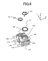
- Fig. 6 a perspective view illustrating a mounting structure of the objective lenses 110 and 111
- Fig. 1 is a perspective view showing an optical-means driving device 105 and its surrounding main components in Embodiment 1 of the present invention
- Fig. 2 a perspective view illustrating the optical-means driving device 105
- Fig. 3 a three-view drawing of the optical-means driving device 105
- Fig. 4 an exploded diagram of the optical-means
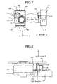
- FIG. 7 a front view and a side view for explaining a mounting state of the objective lenses 110 and 111, and a protector 113
- Fig. 8 a cross-sectional side view taken from the line A - A of Fig. 1
- Fig. 9 a cross-sectional side view taken from the line B - B of Fig. 2
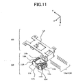
- Fig. 10 a perspective view of a movable unit 118 and a fixed unit 123 of the optical-means driving device 105 in Embodiment 1 each of which having been preassembled
- Fig. 11 another perspective view observed from a different viewpoint for Fig. 10 .
- the Z-axis is denoted in parallel with an optical axis of the objective lenses each; the X-axis, denoted in a radial direction of a discoid recording medium, perpendicular to the Z-axis; and the Y-axis, denoted in the direction orthogonal to these two axes.
- numeral 101 designates an optical disk that is an optical information-recording medium; numeral 102, a turntable on which the optical disk 101 is attached; and numeral 103, a spindle motor for rotating the turntable 102.
- Numeral 104 designates an optics base that is mounted with a plurality of light sources such as semiconductor lasers (not shown) and the optical-means driving device 105, and is supported so as to be movable in radial directions (X-axis directions) of the optical disk 101 by guide shafts 106a and 106b.
- numeral 107 designates a cover to protect the optical-means driving device 105.
- a light beam whose wavelength is in the vicinity of 405 nm and emitted from such a blue semiconductor-laser is designated as a light beam ⁇ ; and a red light-beam whose wavelength is in the vicinity of 660 nm and a light beam whose wavelength is in the vicinity of 780 nm, emitted from a two-wavelength semiconductor-laser, are designated as a light beam ⁇ .
- Numerals 110 and 111 designate the objective lenses that focus the light beam ⁇ and the light beam ⁇ on the optical disk 101, respectively; for example, the objective lens 110 is used for a BD (Blu-ray disc), and the objective lens 111, for two focal points compatible with a CD (compact disc) and a DVD (digital versatile disc); starting with outer dimensions, specifications of the focal length, an active range (working distance) or the like differ from each other.
- the objective lens 110 is used for a BD (Blu-ray disc)
- the objective lens 111 for two focal points compatible with a CD (compact disc) and a DVD (digital versatile disc); starting with outer dimensions, specifications of the focal length, an active range (working distance) or the like differ from each other.
- the objective lens 110 and the objective lens 111 are arranged in such a way that the optical axes of the objective lenses are parallel to the Z-axis, and a line segment connecting between the centers of the objective lenses is shifted at a predetermined angle with respect to the X-axis.
- the angle is selected at 45 degrees; thereby, it is also configured that, by way of a wavelength selective mirror (not shown) placed below the objective lens 110 and the objective lens 111, the light beam ⁇ and the light beam ⁇ each are incident thereto from a direction at an angle of 45 degrees that is equal to the placement angle of the objective lens 110 and the objective lens 111.
- a lens holder 112 is formed by plastic that is light in weight and high in stiffness, and is approximately shaped in a rectangular parallelepiped having faces perpendicular to the Z-axis, lateral sides perpendicular to the X-axis, and lateral sides perpendicular to the Y-axis.
- the objective lens 111 is arranged in such a manner that, when the optical disk 101 is a "DVD," a focal point is formed in a state in Fig. 5(A) , and when a "CD,” the lens holder 112 moves in the Z-axis directions so that a focal point is formed in a state in Fig. 5(B) .
- a position of the lens holder 112 along the Z-axis is arranged in such a manner that the position of the objective lens 110 used for the "BD" in this embodiment is determined along the Z-axis so that a focal point is formed at the position in Fig. 5(C) so as to come between the position in Fig. 5(A) and the position in Fig. 5(B) .
- a cutout 112a is made so as to mount the objective lens 111.
- a state in which the objective lenses 110 and 111 are mounted on the lens holder 112 demonstrates such a state that a portion of the objective lens 111 hides under the objective lens 110; thus, the perimeters thereof are placed overlapping with each other when viewed along the optical axes.
- the protector 113 that is a protection means against an occurrence of a collision between the optical disk 101 and the objective lenses is fixed upon the top face of the objective lens 111 that is the one whose distance to the optical disk 101 is larger than the other.
- Two protrusions 113a and 113b are formed upon the top face of the protector 113 so that the tips of the protrusions 113a and 113b are placed slightly more projective than the top face of the objective lens 110.
- a cutout 112b is made at a mounting portion for the objective lens 110 in the lens holder 112 in an X-axis direction thereof; then, a portion of the perimeter of the objective lens 110 extending from the cutout 112b is fixed overhanging from the lens holder 112.
- Fig. 8 is a cross-sectional side view showing positional relationship among the optical disk 101, the turntable 102, the spindle motor 103, the objective lens 110 and the lens holder 112 when the optics base 104 is placed on the innermost side of the optical disk 101.
- a diameter of the spindle motor 103 is generally made smaller than a diameter of the turntable 102.
- it is configured that the perimeters of the turntable 102 and the objective lens 110 are set closest with each other.
- a light shield 112c is formed in a lower portion of the lens holder 112 so that the light beam ⁇ is prevented from leaking to the optical disk 101.
- Fig. 10 and Fig. 11 illustrate a perspective view of the movable unit 118 and the fixed unit 123 that are in a state individually assembled (partially refer to Fig. 9 ).
- the movable unit 118 will be explained.
- the lens holder 112 at the center of a pair of lateral side walls each perpendicular to the Y-axis, there provided are oblong holes 112d and 112e; two continuously wound focusing coils 114a and 114b are introduced and fixed thereinside where each of these has the coil-winding axis in the Z-axis directions; and then, on the pair of lateral side walls each perpendicular to the Y-axis, four continuously wound tracking coils 115a, 115b, 115c and 115d are fixed by adhesion where each of these has the coil-winding axis in the Y-axis directions.
- the top face of the lens holder 112 is covered by wall portions 112f and 112g each having a downward column; thus, it is so arranged that the light beam ⁇ and the light beam ⁇ do not leak also in the Y-axis directions of the lens holder to the optical disk 101.
- movable-side boards 117a and 117b are fixed to the lens holder 112 on a pair of lateral side walls thereof perpendicular to the X-axis each so as to solder the coil ends of the focusing coils 114a and 114b, the tracking coils 115a, 115b, 115c and 115d, and the tilting coils 116a, 116b, 116c and 116d, so that the movable unit 118 is configured.
- a base yoke 119 is worked by pressing upon a magnetic material such as a cold-rolled steel plate, and has inner yoke portions 119a and 119b each provided with a slit at the center thereof; interposing the inner yoke portions 119a and 119b, magnets 120a and 120b magnetized in parallel in such a way that the identical poles face each other are fixed on fixing plates 119b and 119d of the base yoke 119, respectively; thereby, magnetic gaps are made to form closed circuits.
- a gel holder 122 fixed with fixed-side boards 121a and 121b is fixed by adhesion onto the base yoke 119. According to the manner described above, the fixed unit 123 is configured.
- wires 124a through 124f each that are conductive elastic members placed in parallel with one another in a respective group of three are fixed to the movable-side boards 117a and 117b by soldering; and other ends of the wires each are fixed to the fixed-side boards 121a and 121b by soldering.
- the movable unit 118 is elastically supported by the wires 124a through 124f so as to be movable in the Z-axis directions (focusing directions), the X-axis directions (tracking directions) and the directions of rotation about the Y-axis (tilting directions) with respect to the fixed unit 123.
- the wires 124a and 124d are connected to the focusing coils 114a and 114b; the wires 124b and 124e, connected to the tracking coils 115a, 115b, 115c and 115d; and the wires 124c and 124f, connected to the tilting coils 116a, 116b, 116c and 116d.
- the wires 124a through 124f are extended so as not to cut across the X and Z plane that includes the central axis of the spindle motor 103.
- Rectangular openings 122a and 122b are formed in the gel holder 122 for the fixed-side boards (refer to Fig. 4 ); in the rectangular openings 122a and 122b, gelatinous damper agents 125a and 125b that are of an ultraviolet curable type are filled so as to enclose around the end portions of the wires 124a through 124f each.
- the inner yoke portions 119a and 119b are introduced into the holes of the tilting coils 116a, 116b, 116c and 116d oriented in a Z-axis direction, and into the holes of the focusing coils 114a and 114b oriented in the Z-axis direction; each side of the tracking coils 115a, 115b, 115c and 115d oriented in the Z-axis direction is placed so as to face the magnets 120a and 120b with each other.
- magnetic circuits each configured by the inner yoke portions 119a and 119b, and the magnets 120a and 120b are formed to interpose the lens holder 112 therebetween in the Y-axis directions that observe a tangential direction of the optical disk 101.
- the optical-means driving device configured as described above.
- the focusing coils 114a and 114b connected in series each are energized by way of the wires 124a and 124d to which the focusing coils 114a and 114b are connected.
- electromagnetic force is generated along the Z-axis by mutual action with magnetic fields generated from the magnets 120a and 120b; the movable unit 118, the objective lenses 110 and 111 are driven to move in approximately perpendicular directions (Z-axis directions) with respect to the optical disk 101, so that a focusing control of the light spot is performed.
- the tracking coils 115a through 115d connected in series each are energized by way of the wires 124b through 124e to which the tracking coils 115a through 115d are connected.
- electromagnetic force is generated by mutual action with magnetic fields generated from the magnets 120a and 120b; the movable unit 118, the objective lenses 110 and 111 are driven to move in radial directions (X-axis directions) of the optical disk 101, so that a tracking control of the light spot is performed.
- the tilting coils 116a through 116d connected in series each are energized by way of the wires 124c through 124f to which the tilting coils 116a through 116d are connected.
- the tilting coils 116a and 116c, and the tilting coils 116b and 116d are placed so that winding directions of the sets each are made in opposite orientations, by mutual action with magnetic fields generated from the magnets 120a and 120b, electromagnetic forces are generated in the tilting coils 116a and 116c, and the tilting coils 116b and 116d that are mutually opposite in the Z-axis directions, so that moment is generated in a direction of rotation about the Y-axis, and the movable unit 118 and as a result, the objective lenses 110 and 111 are moved rotationally; thereby, with respect to a tilt in radial directions (X-axis directions) of the optical disk 101, a radial tilting control of the light spot is performed so as to keep the optical axis of the objective lenses 110 and 111 always perpendicular to the optical disk.
- the movable unit 118 is elastically supported by the six wires 124a through 124f so as to be movable in the Z-axis directions, the X-axis directions and the directions of rotation about the Y-axis, the unit returns to a reference operating position along the Z-axis when energization to the focusing coils 114a and 114b is ceased; the unit returns to a reference operating position in the X-axis directions when energization to the tracking coils 115a through 115d is ceased; and the unit returns to a reference operating position in a direction of rotation about the Y-axis when energization to the tilting coils 116a through 116d is ceased.
- the movable unit 118 moves in a direction to release from the optical disk 101 in a focusing-control direction, the wall portions 112f and 112g of the lens holder 112, and the inner yoke portions 118a and 118b are in contact with each other, so that the movable range is restricted.
- the wires 124a and 124d are connected to the focusing coils 114a and 114b; the wires 124b and 124e, connected to the tracking coils 115a, 115b, 115c and 115d; and the wires 124c and 124f, connected to the tilting coils 116a, 116b, 116c and 116d.
- positions of the wires are not necessarily limited to the positions described above; among six of the wires 124a through 124f, it is simply required to have every two wires as a pair connected to focusing coils, tracking coils or tilting coils.
- the magnetic circuits made of the magnets 120a and 120b, and the inner yoke portions 119a and 119b are formed to interpose the lens holder 112 therebetween in a tangential direction of the optical disk 101, and the inner yoke portions 119a and 119b are placed inside the lens holder 112 in which the top face thereof is closed; therefore, it becomes possible to provide an optical-means driving device that is high in sensitivity, high in stiffness and small in size in radial directions of the optical disk 101.
- the two objective lenses 110 and 111 are placed being shifted with reference to the X-axis directions, dimensions between the centers of the two objective lenses 110 and 111 in a radial direction (X-axis direction) of the optical disk 101 can be made small; thereby, it is possible to obtain an optical-means driving device capable of reading/writing information from/on the innermost track of the optical disk 101 in an easier manner without interfering with the turntable 102 or the spindle motor 103 when the objective lens 111 placed on the outer side is used.
- the light shield 112c is formed so that it prevents leakage of an incident light-beam; therefore, it is possible to avoid interference between the light shield 112c and the turntable 102, and to place the optical-means driving device 105 closer to the inner side of the optical disk 101.
- the light shield 112c which therefore acts as a balancer that keeps on a weight balance of the movable unit 118.
- the cutout 112b is made at a portion in adjacent to the turntable 102; and a perimeter portion of the objective lens 110 is overhanging from the lens holder 112. Therefore, it becomes possible to place the centers of the objective lenses 110 and 111 closer to the inner track of the optical disk 101.
- the two objective lenses 110 and 111 each are placed at different heights along the Z-axis, and portions of the two objective lenses 110 and 111 are placed overlapping with each other when viewed along the Z-axis, it becomes possible not only to obtain a movable unit that is compact and light in weight, but also to place the objective lens 111 placed on the outer side of the optical disk 101 closer to the inner side of the optical disk 101.
- the lens holder 112 can be moved rotationally on the Y-axis, so that it becomes possible to perform a radial tilting control.
- a focusing position of the objective lens 110 is placed so as to come between two focusing positions of the objective lens 111 having two focal points, positional shifts due to focusing movement can be made small even when recording or playback is performed on various kinds of such a different optical disk 101, so that it becomes possible not only to reduce changes in property that depends on a kind of the optical disk, but also to design to make an adjustable focusing range small; therefore, a compact optical-means driving device can be made available.
Landscapes
- Physics & Mathematics (AREA)
- Optics & Photonics (AREA)
- Optical Recording Or Reproduction (AREA)
- Optical Head (AREA)
Abstract
Description
- The present invention relates to optical disk apparatus such as a DVD (digital versatile disc) recorder and a BD player used for performing information recording to or playback from an information recording medium, in particular, to optical-means driving devices.
- In recent years, there developed are various kinds of optical disks each of which is different in the recording density, a cover-layer thickness or the like; for example there are a CD (compact disc) whose usable wavelength is in the vicinity of 780 nm, a DVD (digital versatile disc) whose usable wavelength is in the vicinity of 660 nm, a BD (Blu-ray disc) and an HD-DVD (high definition DVD) whose usable wavelength is in the vicinity of 405 nm, and the like. In such an optical disk apparatus adapted to a plurality of kinds of optical disks whose usable wavelengths are different to one another, there is an apparatus which includes a plurality of objective lenses so as to obtain a focusing spot corresponding to each of the optical disks. (For example, refer to Patent Document 1.)
[Patent Document 1] Japanese Laid-Open Patent Publication No.2003-281758 Fig. 2 through Fig. 13) - However, in the optical disk apparatus in Patent Document 1, the weight of a movable unit increases to mount a plurality of objective lenses on a lens holder; thereby, in order to obtain required driving forces, it has been necessary to provide complex magnetic circuits having inner yokes. For this reason, introduction holes are provided for the lens holder so as to introduce the inner yokes thereinto, which has caused a problem in which it is difficult to increase stiffness of the lens holder.
- The present invention has been directed at solving those problems described above, and an object of the invention is to obtain, in an optical-means driving device in which a plurality of objective lenses is held in a lens holder, the optical-means driving device that is compact and high in stiffness.
- An optical-means driving device according to the present invention comprises:
- a holder for holding a plurality of optical means each of which focuses on an optical disk a light beam outputted from a light source, focusing coils, and tracking coils;
- a plurality of elastic support members for supporting the holder so as to be movable in an approximately radial direction of the optical disk and in an approximately perpendicular direction to the optical disk; and
- a base for holding inner yokes placed inside the holder, and magnets that generate magnetic fields with respect to the focusing coils and to the tracking coils; the optical-means driving device is characterized in that
- the top face of the holder has a closed structure over the inner yokes.
- According to the present invention, because the top face of a holder has a closed structure over inner yokes, there exists an effect in which a small-size optical-means driving device with high stiffness can be obtained.
-
-
Fig. 1 is a perspective view illustrating an optical-means driving device and its surrounding main components in Embodiment 1; -
Fig. 2 is a perspective view illustrating the optical-means driving device in Embodiment 1; -
Fig. 3 is a three-view drawing of the optical-means driving device 105 in Embodiment 1; -
Fig. 4 is an exploded diagram of the optical-means driving device in Embodiment 1; -
Fig. 5 is an illustrative diagram of arranged heights of objective lenses in Embodiment 1; -
Fig. 6 is a perspective view illustrating a mounting structure of the objective lenses in Embodiment 1; -
Fig. 7 is a front view and a side view for explaining a mounting state of the objective lenses and a protector in Embodiment 1; -
Fig. 8 is a cross-sectional side view taken from the line A - A ofFig. 1 in Embodiment 1; -
Fig. 9 is a cross-sectional side view taken from the line B - B ofFig. 2 in Embodiment 1; -
Fig. 10 is a perspective view of a movable unit and a fixed unit of the optical-means driving device in Embodiment 1 each of which having been preassembled; and -
Fig. 11 is another perspective view observed from a different viewpoint forFig. 10 in Embodiment 1. - "101" designates an optical disk; "102," turntable; "103," spindle motor; "104," optics base; "105," optical-means driving device; "106a," "106b," guide shafts; "107," cover; "108," light beam; "109," light beam; "110," objective lens; "111," objective lens; "112," lens holder; "112a," cutout; "112b," cutout; "112c," light shield; "112f," "112g," wall portions; "113," protector; "114a," "114b," focusing coils; "115a," through "115d," tracking coils; "116a," through "116d," tilting coils; "117a," "117b," movable-side boards; "118," movable unit; "119," base yoke; "119a," "119b," inner-yoke portions; "120a," "120b," magnets; "121a," "121b," fixed-side boards; "122," gel holder; "123," fixed unit; "124a," through "124f," wires; and "125a," "125b," gels.
-
Fig. 1 is a perspective view showing an optical-means driving device 105 and its surrounding main components in Embodiment 1 of the present invention;Fig. 2 , a perspective view illustrating the optical-means driving device 105;Fig. 3 , a three-view drawing of the optical-means driving device 105;Fig. 4 , an exploded diagram of the optical-means driving device 105;Fig. 5 , an illustrative diagram of arranged heights ofobjective lenses means driving device 105;Fig. 6 , a perspective view illustrating a mounting structure of theobjective lenses Fig. 7 , a front view and a side view for explaining a mounting state of theobjective lenses protector 113;Fig. 8 , a cross-sectional side view taken from the line A - A ofFig. 1 ;Fig. 9 , a cross-sectional side view taken from the line B - B ofFig. 2 ;Fig. 10 , a perspective view of amovable unit 118 and afixed unit 123 of the optical-means driving device 105 in Embodiment 1 each of which having been preassembled; andFig. 11 , another perspective view observed from a different viewpoint forFig. 10 . - In addition, as for the X, Y and Z coordinate axes indicated in each of the figures, the Z-axis is denoted in parallel with an optical axis of the objective lenses each; the X-axis, denoted in a radial direction of a discoid recording medium, perpendicular to the Z-axis; and the Y-axis, denoted in the direction orthogonal to these two axes.
- In what follows, Embodiment 1 of the present invention will be explained by using
Fig. 1 through Fig. 11 . InFig. 1 through Fig. 11 ,numeral 101 designates an optical disk that is an optical information-recording medium;numeral 102, a turntable on which theoptical disk 101 is attached; andnumeral 103, a spindle motor for rotating theturntable 102. Numeral 104 designates an optics base that is mounted with a plurality of light sources such as semiconductor lasers (not shown) and the optical-means driving device 105, and is supported so as to be movable in radial directions (X-axis directions) of theoptical disk 101 byguide shafts numeral 107 designates a cover to protect the optical-means driving device 105. - As for light beams emitted from the light sources not shown in the figures, such as semiconductor lasers (not shown), a light beam whose wavelength is in the vicinity of 405 nm and emitted from such a blue semiconductor-laser is designated as a light beam α; and a red light-beam whose wavelength is in the vicinity of 660 nm and a light beam whose wavelength is in the vicinity of 780 nm, emitted from a two-wavelength semiconductor-laser, are designated as a light beam β.
Numerals optical disk 101, respectively; for example, theobjective lens 110 is used for a BD (Blu-ray disc), and theobjective lens 111, for two focal points compatible with a CD (compact disc) and a DVD (digital versatile disc); starting with outer dimensions, specifications of the focal length, an active range (working distance) or the like differ from each other. - The
objective lens 110 and theobjective lens 111 are arranged in such a way that the optical axes of the objective lenses are parallel to the Z-axis, and a line segment connecting between the centers of the objective lenses is shifted at a predetermined angle with respect to the X-axis. In this embodiment, the angle is selected at 45 degrees; thereby, it is also configured that, by way of a wavelength selective mirror (not shown) placed below theobjective lens 110 and theobjective lens 111, the light beam α and the light beam β each are incident thereto from a direction at an angle of 45 degrees that is equal to the placement angle of theobjective lens 110 and theobjective lens 111. Alens holder 112 is formed by plastic that is light in weight and high in stiffness, and is approximately shaped in a rectangular parallelepiped having faces perpendicular to the Z-axis, lateral sides perpendicular to the X-axis, and lateral sides perpendicular to the Y-axis. Here, theobjective lens 111 is arranged in such a manner that, when theoptical disk 101 is a "DVD," a focal point is formed in a state inFig. 5(A) , and when a "CD," thelens holder 112 moves in the Z-axis directions so that a focal point is formed in a state inFig. 5(B) . When theoptical disk 101 is a "BD," a position of thelens holder 112 along the Z-axis is arranged in such a manner that the position of theobjective lens 110 used for the "BD" in this embodiment is determined along the Z-axis so that a focal point is formed at the position inFig. 5(C) so as to come between the position inFig. 5(A) and the position inFig. 5(B) . - Mounting positions of the objective lenses will be explained by using
Fig. 6 andFig. 7 . At a mounting portion for theobjective lens 110 formed in thelens holder 112, acutout 112a is made so as to mount theobjective lens 111. A state in which theobjective lenses lens holder 112 demonstrates such a state that a portion of theobjective lens 111 hides under theobjective lens 110; thus, the perimeters thereof are placed overlapping with each other when viewed along the optical axes. Here, by comparing the distances between each of theobjective lenses optical disk 101, theprotector 113 that is a protection means against an occurrence of a collision between theoptical disk 101 and the objective lenses is fixed upon the top face of theobjective lens 111 that is the one whose distance to theoptical disk 101 is larger than the other. Twoprotrusions protector 113 so that the tips of theprotrusions objective lens 110. In addition, acutout 112b is made at a mounting portion for theobjective lens 110 in thelens holder 112 in an X-axis direction thereof; then, a portion of the perimeter of theobjective lens 110 extending from thecutout 112b is fixed overhanging from thelens holder 112. -
Fig. 8 is a cross-sectional side view showing positional relationship among theoptical disk 101, theturntable 102, thespindle motor 103, theobjective lens 110 and thelens holder 112 when theoptics base 104 is placed on the innermost side of theoptical disk 101. A diameter of thespindle motor 103 is generally made smaller than a diameter of theturntable 102. In a case of this embodiment, it is configured that the perimeters of theturntable 102 and theobjective lens 110 are set closest with each other. Alight shield 112c is formed in a lower portion of thelens holder 112 so that the light beam α is prevented from leaking to theoptical disk 101. -
Fig. 10 andFig. 11 illustrate a perspective view of themovable unit 118 and thefixed unit 123 that are in a state individually assembled (partially refer toFig. 9 ). First, themovable unit 118 will be explained. As for thelens holder 112 at the center of a pair of lateral side walls each perpendicular to the Y-axis, there provided are oblongholes coils wound tracking coils lens holder 112 where the focusingcoils coils - In addition, as shown by a cross-sectional side view in
Fig. 9 , the top face of thelens holder 112 is covered bywall portions optical disk 101. Moreover, movable-side boards lens holder 112 on a pair of lateral side walls thereof perpendicular to the X-axis each so as to solder the coil ends of the focusingcoils tracking coils tilting coils movable unit 118 is configured. - Next, a configuration of the
fixed unit 123 will be explained. Abase yoke 119 is worked by pressing upon a magnetic material such as a cold-rolled steel plate, and hasinner yoke portions inner yoke portions magnets fixing plates base yoke 119, respectively; thereby, magnetic gaps are made to form closed circuits. In addition, agel holder 122 fixed with fixed-side boards base yoke 119. According to the manner described above, thefixed unit 123 is configured. - As shown in
Fig. 2 andFig. 3 , one ends ofwires 124a through 124f each that are conductive elastic members placed in parallel with one another in a respective group of three are fixed to the movable-side boards side boards movable unit 118 is elastically supported by thewires 124a through 124f so as to be movable in the Z-axis directions (focusing directions), the X-axis directions (tracking directions) and the directions of rotation about the Y-axis (tilting directions) with respect to the fixedunit 123. - For example, the
wires coils wires wires wires 124a through 124f are extended so as not to cut across the X and Z plane that includes the central axis of thespindle motor 103.Rectangular openings gel holder 122 for the fixed-side boards (refer toFig. 4 ); in therectangular openings gelatinous damper agents wires 124a through 124f each. - In addition, the
inner yoke portions coils coils magnets inner yoke portions magnets lens holder 112 therebetween in the Y-axis directions that observe a tangential direction of theoptical disk 101. - The operations of the optical-means driving device configured as described above will be explained. First, when focusing error in a light spot is controlled, by supplying a focusing control voltage to predetermined terminals (not shown in the figures) of the fixed-
side boards coils wires coils magnets movable unit 118, theobjective lenses optical disk 101, so that a focusing control of the light spot is performed. - When tracking displacement of a light spot is controlled, by supplying a tracking control voltage to predetermined terminals (not shown in the figures) of the fixed-
side boards tracking coils 115a through 115d connected in series each are energized by way of thewires 124b through 124e to which thetracking coils 115a through 115d are connected. According to this arrangement, electromagnetic force is generated by mutual action with magnetic fields generated from themagnets movable unit 118, theobjective lenses optical disk 101, so that a tracking control of the light spot is performed. - Next, when radial tilting displacement of a light spot is contorolled, by supplying a tilting control voltage to predetermined terminals (not shown in the figures) of the fixed-
side boards coils 116a through 116d connected in series each are energized by way of thewires 124c through 124f to which thetilting coils 116a through 116d are connected. Because the tilting coils 116a and 116c, and the tilting coils 116b and 116d are placed so that winding directions of the sets each are made in opposite orientations, by mutual action with magnetic fields generated from themagnets movable unit 118 and as a result, theobjective lenses optical disk 101, a radial tilting control of the light spot is performed so as to keep the optical axis of theobjective lenses - In addition, because the
movable unit 118 is elastically supported by the sixwires 124a through 124f so as to be movable in the Z-axis directions, the X-axis directions and the directions of rotation about the Y-axis, the unit returns to a reference operating position along the Z-axis when energization to the focusingcoils tracking coils 115a through 115d is ceased; and the unit returns to a reference operating position in a direction of rotation about the Y-axis when energization to thetilting coils 116a through 116d is ceased. Moreover, because the end portions of the sixwires 124a through 124f each fixed on the fixed-side boards gelatinous damper agents gel holder 122 so as to enclose the surroundings, damping is given to themovable unit 118; thereby, a good focusing control characteristic, a tracking control characteristic and a radial tilting control characteristic can be obtained, and at the same time unwanted vibrations from outside are not easily transferred to themovable unit 118. In addition, when themovable unit 118 moves in a direction to release from theoptical disk 101 in a focusing-control direction, thewall portions lens holder 112, and the inner yoke portions 118a and 118b are in contact with each other, so that the movable range is restricted. - In this embodiment, it has been explained that the
wires coils wires wires wires 124a through 124f, it is simply required to have every two wires as a pair connected to focusing coils, tracking coils or tilting coils. - As described above, because the magnetic circuits made of the
magnets inner yoke portions lens holder 112 therebetween in a tangential direction of theoptical disk 101, and theinner yoke portions lens holder 112 in which the top face thereof is closed; therefore, it becomes possible to provide an optical-means driving device that is high in sensitivity, high in stiffness and small in size in radial directions of theoptical disk 101. - In addition, because the two
objective lenses objective lenses optical disk 101 can be made small; thereby, it is possible to obtain an optical-means driving device capable of reading/writing information from/on the innermost track of theoptical disk 101 in an easier manner without interfering with theturntable 102 or thespindle motor 103 when theobjective lens 111 placed on the outer side is used. - That is to say, because a plurality of objective lenses is placed at an angle with a radial direction of an optical disk, in particular with an objective lens placed on the outer side of the optical disk, it becomes possible to read/write the information from/on the innermost track of the optical disk. In addition, it is no more necessary to make small in diameter by cutting out a turntable that holds the optical disk. Moreover, use of a spindle motor small in diameter and demanding in price is no more required, so that it becomes possible to reduce costs.
- In addition, in a lower portion of a lateral side wall of the
lens holder 112 in an X-axis direction, thelight shield 112c is formed so that it prevents leakage of an incident light-beam; therefore, it is possible to avoid interference between thelight shield 112c and theturntable 102, and to place the optical-means driving device 105 closer to the inner side of theoptical disk 101. In addition, on the opposite side to theobjective lens 110 and theobjective lens 111 with respect to the Z-axis directions, there placed is thelight shield 112c, which therefore acts as a balancer that keeps on a weight balance of themovable unit 118. - In addition, it is configured that, at the mounting portion of the
lens holder 112 for theobjective lens 110, thecutout 112b is made at a portion in adjacent to theturntable 102; and a perimeter portion of theobjective lens 110 is overhanging from thelens holder 112. Therefore, it becomes possible to place the centers of theobjective lenses optical disk 101. - In addition, because the two
objective lenses objective lenses objective lens 111 placed on the outer side of theoptical disk 101 closer to the inner side of theoptical disk 101. - In addition, because the
tilting coils 116a through 116d are also mounted on thelens holder 112, thelens holder 112 can be moved rotationally on the Y-axis, so that it becomes possible to perform a radial tilting control. - In addition, because a focusing position of the
objective lens 110 is placed so as to come between two focusing positions of theobjective lens 111 having two focal points, positional shifts due to focusing movement can be made small even when recording or playback is performed on various kinds of such a differentoptical disk 101, so that it becomes possible not only to reduce changes in property that depends on a kind of the optical disk, but also to design to make an adjustable focusing range small; therefore, a compact optical-means driving device can be made available. - Moreover, because a configuration is adopted to place the
protector 113 having protruded portions slightly more projective than the top face of theobjective lens 110 that is near to theoptical disk 101 upon the top face of theobjective lens 111 that is far from theoptical disk 101; therefore, such a protector that protects theoptical disk 101 can be made in an inexpensive and simple shape.
Claims (10)
- An optical-means driving device, comprising:a holder for holding a plurality of optical means each of which focuses on an optical disk a light beam outputted from a light source, focusing coils, and tracking coils;a plurality of elastic support members for supporting said holder so as to be movable in an approximately radial direction of the optical disk and in an approximately perpendicular direction to the optical disk; anda base for holding inner yokes placed inside said holder, and magnets that generate magnetic fields with respect to the focusing coils and to the tracking coils; the optical-means driving devicecharacterized in that
the top face of said holder has a closed structure over the inner yokes. - The optical-means driving device as set forth in claim 1, wherein a line connecting the magnets with the inner yokes is parallel to an approximately tangential direction of the optical disk being perpendicular to the approximately radial direction of the optical disk.
- The optical-means driving device as set forth in claim 1, wherein a plane including the optical axes of at least two optical means out of the plurality of optical means is nonparallel to the approximately radial direction of the optical disk.
- The optical-means driving device as set forth in claim 3, wherein a plane including the optical axes of at least two optical means out of the plurality of optical means forms an angle of some 45 degrees with respect to the approximately radial direction of the optical disk.
- The optical-means driving device as set forth in claim 1, wherein a light shield is formed in a lower portion of a lateral side wall of the holder in the approximately radial direction of the optical disk so as to prevent leakage of the light beam.
- The optical-means driving device as set forth in claim 1, wherein
a cutout is formed on a portion of the holder for mounting at least one optical means in the approximately radial direction of the optical disk; and
the perimeter of said at least one optical means has a portion overhanging from a lateral side of said holder. - The optical-means driving device as set forth in claim 1, wherein the plurality of optical means each is placed at different heights in a direction perpendicular to the optical disk, and is placed so as to overlap with one another in the direction perpendicular to the optical disk.
- The optical-means driving device as set forth in claim 1, wherein the holder holds tilting coils and thereby can be rotationally moved on an axis in an approximately tangential direction of the optical disk.
- The optical-means driving device as set forth in claim 1, wherein
the plurality of optical means includes an objective lens having one focal point and an objective lens having two focal points; and
the objective lens having one focal point and the objective lens having two focal points are placed in such a way that a focusing position by the objective lens having one focal point comes between two focusing positions by that having two focal points. - The optical-means driving device as set forth in claim 1, wherein
the top face of the plurality of optical means each is placed at different heights in a direction perpendicular to the optical disk; and
a protection member is attached on an optical means whose top face is not nearest to the optical disk so that the top of the protection member is higher than the optical means top face being nearest to the optical disk.
Applications Claiming Priority (2)
| Application Number | Priority Date | Filing Date | Title |
|---|---|---|---|
| JP2006092016 | 2006-03-29 | ||
| PCT/JP2007/050885 WO2007111034A1 (en) | 2006-03-29 | 2007-01-22 | Optical means drive device |
Publications (3)
| Publication Number | Publication Date |
|---|---|
| EP2001018A2 true EP2001018A2 (en) | 2008-12-10 |
| EP2001018A9 EP2001018A9 (en) | 2009-03-11 |
| EP2001018A4 EP2001018A4 (en) | 2009-04-08 |
Family
ID=38540969
Family Applications (1)
| Application Number | Title | Priority Date | Filing Date |
|---|---|---|---|
| EP07707148A Withdrawn EP2001018A4 (en) | 2006-03-29 | 2007-01-22 | DEVICE FOR CONTROLLING OPTICAL MEANS |
Country Status (5)
| Country | Link |
|---|---|
| US (1) | US8042130B2 (en) |
| EP (1) | EP2001018A4 (en) |
| JP (1) | JP4768013B2 (en) |
| CN (1) | CN101401157B (en) |
| WO (1) | WO2007111034A1 (en) |
Families Citing this family (1)
| Publication number | Priority date | Publication date | Assignee | Title |
|---|---|---|---|---|
| EP1939865A1 (en) * | 2006-12-28 | 2008-07-02 | Deutsche Thomson OHG | Pickup for accessing moving storage media and drive having the pickup |
Family Cites Families (31)
| Publication number | Priority date | Publication date | Assignee | Title |
|---|---|---|---|---|
| NL8600437A (en) * | 1986-02-21 | 1987-09-16 | Philips Nv | ELECTRO-OPTICAL DEVICE. |
| KR950013703B1 (en) | 1991-05-13 | 1995-11-13 | 삼성전자주식회사 | Objective lens drive of optical pickup |
| KR950004797B1 (en) * | 1991-12-31 | 1995-05-10 | 삼성전자주식회사 | Optical pickup device for laser disc player |
| JPH0696458A (en) * | 1992-07-28 | 1994-04-08 | Asahi Optical Co Ltd | Electromagnetic drive device for objective lens of optical information recording / reproducing device |
| US5488603A (en) * | 1993-06-21 | 1996-01-30 | Matsushita Electric Industrial Co., Ltd. | Optical information recording reproducing apparatus with first and second electrokinetic transducers at respective distances |
| US5663840A (en) * | 1994-06-14 | 1997-09-02 | Nec Corporation | Objective lens actuator for optical head and used for high speed access |
| KR100230250B1 (en) * | 1994-12-26 | 1999-11-15 | 윤종용 | Method and apparatus for correcting aberration by tilting optical disc |
| US5768037A (en) * | 1995-10-06 | 1998-06-16 | Eastman Kodak Company | Actuator with single surface-field motor |
| US5673247A (en) * | 1995-11-29 | 1997-09-30 | Sharp Kabushiki Kaisha | Optical pickup having two objective lenses |
| JPH09297927A (en) * | 1996-05-07 | 1997-11-18 | Sharp Corp | Optical pickup device |
| JP3776560B2 (en) | 1997-05-14 | 2006-05-17 | オリンパス株式会社 | Optical system drive |
| KR20010046053A (en) * | 1999-11-10 | 2001-06-05 | 이형도 | Apparatus for moving an objective lens for optical pick-up |
| JP2002208150A (en) | 2001-01-10 | 2002-07-26 | Victor Co Of Japan Ltd | Optical pickup device |
| JP2002245650A (en) | 2001-02-20 | 2002-08-30 | Toshiba Corp | Objective lens driving device and optical disk device |
| JP2003045054A (en) * | 2001-07-31 | 2003-02-14 | Sumida Corporation | Optical pickup |
| KR100636127B1 (en) | 2001-12-01 | 2006-10-19 | 삼성전자주식회사 | Actuator for Optical Pickup |
| JP2003173557A (en) * | 2001-12-05 | 2003-06-20 | Sanyo Electric Co Ltd | Optical pickup device |
| JP3625207B2 (en) * | 2002-05-23 | 2005-03-02 | 三菱電機株式会社 | Optical means driving device |
| CN100361206C (en) * | 2003-01-22 | 2008-01-09 | 松下电器产业株式会社 | Optical head and disc device |
| JP2004265512A (en) * | 2003-02-28 | 2004-09-24 | Toshiba Corp | Optical head device, optical disk device using optical head device, and heat radiation mechanism |
| JP2005011433A (en) * | 2003-06-19 | 2005-01-13 | Matsushita Electric Ind Co Ltd | Optical head |
| JP2005174485A (en) * | 2003-12-12 | 2005-06-30 | Matsushita Electric Ind Co Ltd | Objective lens, optical pickup device, and optical disk device |
| EP1647016A2 (en) * | 2003-07-07 | 2006-04-19 | Matsushita Electric Industrial Co., Ltd. | Objective lens, optical pick-up device, and optical disk device |
| JP3818282B2 (en) * | 2003-08-19 | 2006-09-06 | ソニー株式会社 | Optical pickup and disk drive device |
| KR100555527B1 (en) * | 2003-11-13 | 2006-03-03 | 삼성전자주식회사 | High sensitivity optical pickup actuator and optical recording and / or reproducing apparatus employing the same |
| KR100532497B1 (en) * | 2004-01-27 | 2005-11-30 | 삼성전자주식회사 | Magnetic circuit and optical pickup actuator and optical recording and/or reproducing apparatus employing it |
| JP2005302163A (en) * | 2004-04-13 | 2005-10-27 | Sony Corp | Optical pickup and disk drive device |
| JP2005302162A (en) * | 2004-04-13 | 2005-10-27 | Sony Corp | Optical pickup and disk drive device |
| JP2006079781A (en) * | 2004-09-13 | 2006-03-23 | Sony Corp | Optical pickup and disk drive device |
| US7570547B2 (en) * | 2005-08-22 | 2009-08-04 | Konica Minolta Opto, Inc. | Objective lens unit and optical pickup device |
| JP4542070B2 (en) * | 2006-08-24 | 2010-09-08 | 株式会社日立メディアエレクトロニクス | Optical pickup device and optical disk drive device |
-
2007
- 2007-01-22 US US12/224,395 patent/US8042130B2/en not_active Expired - Fee Related
- 2007-01-22 WO PCT/JP2007/050885 patent/WO2007111034A1/en not_active Ceased
- 2007-01-22 JP JP2008507383A patent/JP4768013B2/en not_active Expired - Fee Related
- 2007-01-22 CN CN2007800090627A patent/CN101401157B/en not_active Expired - Fee Related
- 2007-01-22 EP EP07707148A patent/EP2001018A4/en not_active Withdrawn
Also Published As
| Publication number | Publication date |
|---|---|
| WO2007111034A1 (en) | 2007-10-04 |
| CN101401157B (en) | 2011-07-20 |
| EP2001018A9 (en) | 2009-03-11 |
| JP4768013B2 (en) | 2011-09-07 |
| JPWO2007111034A1 (en) | 2009-08-06 |
| CN101401157A (en) | 2009-04-01 |
| US20100153980A1 (en) | 2010-06-17 |
| US8042130B2 (en) | 2011-10-18 |
| EP2001018A4 (en) | 2009-04-08 |
Similar Documents
| Publication | Publication Date | Title |
|---|---|---|
| US5930214A (en) | Recording/reproducing optical head apparatus compatible with different optical media | |
| KR20030025623A (en) | Apparatus for controlling of lens holder in pick-up | |
| JP4166715B2 (en) | Objective lens driving device, optical pickup device and optical disk device | |
| JP3495123B2 (en) | Optical head device | |
| US20060225087A1 (en) | Optical pickup | |
| EP2001018A9 (en) | Optical means drive device | |
| US20080037383A1 (en) | Objective-lens driving apparatus and optical pickup and optical recording and reproducing apparatus for using same | |
| KR20060047382A (en) | Objective lens drive | |
| US20080151737A1 (en) | Objective lens drive apparatus, optical pickup, and optical disk apparatus | |
| EP2012318B1 (en) | Lens holder for optical pickup and optical pickup having same | |
| EP1909271A1 (en) | Optical pickup actuator capable of preventing adhesive agent in supporting portions of a damper base from deteriorating in strength | |
| US8938746B2 (en) | Object lens driving device and optical disc drive including the same | |
| EP1950751B1 (en) | Objective lens actuator and optical pickup device having the same | |
| JP3892444B2 (en) | Objective lens driving device and optical pickup device using the same | |
| EP1965379A1 (en) | Objective lens actuator and optical pickup device including the same | |
| US20070127327A1 (en) | Objective lens actuator and information recording/playback apparatus | |
| JP3570129B2 (en) | Optical pickup module | |
| US20080037385A1 (en) | Objective-lens driving apparatus and optical pickup and optical recording and reproducing apparatus for using same | |
| KR100374282B1 (en) | Objective lens device for optical pick-up | |
| JPH09265634A (en) | Optical pickup device | |
| KR200144839Y1 (en) | Actuator protection structure | |
| JP2008243251A (en) | Optical head and optical disk apparatus | |
| JPH06314433A (en) | Optical system supporting device | |
| JP2006244592A (en) | Objective lens drive device, optical pickup device, and optical disk drive device | |
| JPH10283641A (en) | Optical system driving device |
Legal Events
| Date | Code | Title | Description |
|---|---|---|---|
| PUAI | Public reference made under article 153(3) epc to a published international application that has entered the european phase |
Free format text: ORIGINAL CODE: 0009012 |
|
| 17P | Request for examination filed |
Effective date: 20080806 |
|
| AK | Designated contracting states |
Kind code of ref document: A2 Designated state(s): DE GB |
|
| PUAB | Information related to the publication of an a document modified or deleted |
Free format text: ORIGINAL CODE: 0009199EPPU |
|
| A4 | Supplementary search report drawn up and despatched |
Effective date: 20090306 |
|
| RBV | Designated contracting states (corrected) |
Designated state(s): DE GB |
|
| 17Q | First examination report despatched |
Effective date: 20091001 |
|
| APBK | Appeal reference recorded |
Free format text: ORIGINAL CODE: EPIDOSNREFNE |
|
| APBN | Date of receipt of notice of appeal recorded |
Free format text: ORIGINAL CODE: EPIDOSNNOA2E |
|
| APBR | Date of receipt of statement of grounds of appeal recorded |
Free format text: ORIGINAL CODE: EPIDOSNNOA3E |
|
| APAF | Appeal reference modified |
Free format text: ORIGINAL CODE: EPIDOSCREFNE |
|
| DAX | Request for extension of the european patent (deleted) | ||
| APAF | Appeal reference modified |
Free format text: ORIGINAL CODE: EPIDOSCREFNE |
|
| APBT | Appeal procedure closed |
Free format text: ORIGINAL CODE: EPIDOSNNOA9E |
|
| STAA | Information on the status of an ep patent application or granted ep patent |
Free format text: STATUS: THE APPLICATION HAS BEEN WITHDRAWN |
|
| 18W | Application withdrawn |
Effective date: 20160723 |