EP1950751B1 - Objective lens actuator and optical pickup device having the same - Google Patents
Objective lens actuator and optical pickup device having the same Download PDFInfo
- Publication number
- EP1950751B1 EP1950751B1 EP08000928A EP08000928A EP1950751B1 EP 1950751 B1 EP1950751 B1 EP 1950751B1 EP 08000928 A EP08000928 A EP 08000928A EP 08000928 A EP08000928 A EP 08000928A EP 1950751 B1 EP1950751 B1 EP 1950751B1
- Authority
- EP
- European Patent Office
- Prior art keywords
- holder
- objective lens
- objective
- lens
- tilt
- Prior art date
- Legal status (The legal status is an assumption and is not a legal conclusion. Google has not performed a legal analysis and makes no representation as to the accuracy of the status listed.)
- Expired - Fee Related
Links
Images


Classifications
-
- G—PHYSICS
- G11—INFORMATION STORAGE
- G11B—INFORMATION STORAGE BASED ON RELATIVE MOVEMENT BETWEEN RECORD CARRIER AND TRANSDUCER
- G11B7/00—Recording or reproducing by optical means, e.g. recording using a thermal beam of optical radiation by modifying optical properties or the physical structure, reproducing using an optical beam at lower power by sensing optical properties; Record carriers therefor
- G11B7/12—Heads, e.g. forming of the optical beam spot or modulation of the optical beam
- G11B7/22—Apparatus or processes for the manufacture of optical heads, e.g. assembly
-
- G—PHYSICS
- G11—INFORMATION STORAGE
- G11B—INFORMATION STORAGE BASED ON RELATIVE MOVEMENT BETWEEN RECORD CARRIER AND TRANSDUCER
- G11B7/00—Recording or reproducing by optical means, e.g. recording using a thermal beam of optical radiation by modifying optical properties or the physical structure, reproducing using an optical beam at lower power by sensing optical properties; Record carriers therefor
- G11B7/08—Disposition or mounting of heads or light sources relatively to record carriers
- G11B7/082—Aligning the head or the light source relative to the record carrier otherwise than during transducing, e.g. adjusting tilt set screw during assembly of head
-
- G—PHYSICS
- G11—INFORMATION STORAGE
- G11B—INFORMATION STORAGE BASED ON RELATIVE MOVEMENT BETWEEN RECORD CARRIER AND TRANSDUCER
- G11B7/00—Recording or reproducing by optical means, e.g. recording using a thermal beam of optical radiation by modifying optical properties or the physical structure, reproducing using an optical beam at lower power by sensing optical properties; Record carriers therefor
- G11B7/12—Heads, e.g. forming of the optical beam spot or modulation of the optical beam
- G11B7/135—Means for guiding the beam from the source to the record carrier or from the record carrier to the detector
- G11B7/1372—Lenses
- G11B7/1374—Objective lenses
-
- G—PHYSICS
- G11—INFORMATION STORAGE
- G11B—INFORMATION STORAGE BASED ON RELATIVE MOVEMENT BETWEEN RECORD CARRIER AND TRANSDUCER
- G11B7/00—Recording or reproducing by optical means, e.g. recording using a thermal beam of optical radiation by modifying optical properties or the physical structure, reproducing using an optical beam at lower power by sensing optical properties; Record carriers therefor
- G11B2007/0003—Recording, reproducing or erasing systems characterised by the structure or type of the carrier
- G11B2007/0006—Recording, reproducing or erasing systems characterised by the structure or type of the carrier adapted for scanning different types of carrier, e.g. CD & DVD
Definitions
- the present invention relates to an objective lens actuator to be equipped in an optical pickup device which irradiates a light beam to an optical recording medium to enable recording and reading information, and, more particularly, to the configuration of an objective lens actuator having a plurality of objective lenses.
- the present invention also relates an optical pickup device having such an objective lens actuator.
- Optical recording mediums such as a compact disc (hereinafter called “CD”) and digital versatile disc (hereinafter called “DVD”), are popular. Further, studies have recently been made on enhancement of the density of optical recording mediums to increase the amount of information thereof, thereby putting optical recording mediums, such as HD-DVD and Blu-ray Disc (hereinafter called “BD”), which can record a huge amount of information to practical use.
- CD compact disc
- DVD digital versatile disc
- BD Blu-ray Disc
- An optical pickup device is used in reading information from such an optical recording medium or writing information thereon.
- NA numerical aperture
- an objective lens whose NA is 0.45 and a light source whose wavelength is 780 nm are used for a CD
- an objective lens whose NA is 0.60 and a light source whose wavelength is 650 nm are used for a DVD
- an objective lens whose NA is 0.85 and a light source whose wavelength is 405 nm are used for a BD.
- optical pickup devices may be used for different optical recording mediums. It is however preferable that a single optical pickup device can compatibly use plural types of optical recording mediums, and multiple optical pickup devices of such a type have been developed. Some of such optical pickup devices have a plurality of objective lenses which can be switched from one to another depending on the type of an optical recording medium in use.
- An objective lens included in an optical pickup device is generally mounted on a lens holder provided in an objective lens actuator, so that the focus direction and tracking direction can be adjusted.
- the optical pickup device that has a plurality of objective lenses, which however should be mounted on the lens holder in such a way that the objective lenses do not tilt with respect to one another (i.e., the center axes of the objective lenses become in parallel).
- the tilt angle of an objective lens actuator having a plurality of objective lenses is normally adjusted using a dominant one of the objective lenses for the optical pickup device so that the influence of comatic aberration or the like is reduced.
- the adhesion angle may be deviated, causing the objective lenses to tilt in relative to one another (relative tilt).
- comatic aberration occurs, bringing about a problem of degrading the quality of information read by the optical pickup device.
- JP-A-2005-174485 discloses a technique of designing objective lenses of an objective lens actuator in such a way as to be able to adjust the swing of the objective lenses about the principal point of the objective lenses and configuring an objective lens holding cylinder which can secure an objective lens by an adhesive or the like in such a way as to be able to adjust the swing of the objective lens holding cylinder about the principal point of the objective lenses. This configuration can reduce a relative tilt between the objective lenses.
- JP-A-2005-174485 requires special processing on the objective lenses to reduce a relative tilt, thereby undesirably increasing the cost of preparing the objective lenses.
- the objective lenses are configured to move along a spherical surface or the like in case of adjusting the tilt angle of each objective lens to reduce the relative tilt between the objective lenses, it is not quite easy to smoothly move the objective lenses, which makes the adjustment work harder.
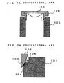
- FIGS. 7A and 7B are diagrams for explaining the configuration of a conventional objective lens actuator;
- FIG. 7A is a diagram showing the cross sections of a part of the lens holder 101 of the objective lens actuator, and the tilt adjusting holder 102 on which the objective lens 100 is mounted, and
- FIG. 7B is an enlarged view of a portion encircled by a dotted line in FIG. 7A .
- the tilt adjusting holder 102 When adjustment of a relative tilt which is executed by moving the tilt adjusting holder 102 is completed, the tilt adjusting holder 102 is securely adhered to the lens holder 101.
- the tilt adjusting holder 102 is moved after a UV adhesive which is cured by UV irradiation is applied to a corresponding portion of the tilt adjusting holder 102 or the lens holder 101 (for example, a filled-in-black portion 103 in FIG. 7B ), not that an adhesive is supplied after the state of securing the tilt adjusting holder 102 is determined. Then, when adjustment of the relative tilt is completed, UV irradiation is performed to cure the adhesive, thereby securing the tilt adjusting holder 102.
- the adhesive is likely to run around to other locations than an adhesion portion 103 at the time of adjusting the relative tilt.
- An adhesive 104 running around from the adhesion portion 103 has a certain thickness.
- JP 10011765 A discloses an optical disk device configured to improve the light condensing characteristics of an objective lens in an optical disk device having plural objective lenses.
- the optical disk device has an objective lens driving device mounting plural objective lenses having different specifications, a first adjusting mechanism and a second adjusting mechanism.
- the first adjusting mechanism is for adjusting the tilts of the objective lenses such that the respective optical axes of the plural objective lenses are parallel with each other
- the second adjusting mechanism is for adjusting the tilt of the objective lens driving device such that the respective optical axes of the plural objective lenses become perpendicular to the disk provided in the objective lens driving device.
- JP 10011765 discloses the preamble of claim 1.
- JP 2006338811 A an optical pickup and its adjusting device is described comprising a spherical base and a wall surface formed at a lens holder, wherein the position of an objective lens is optionally adjusted via the spherical base by providing an intermediate part so as to be in contact with the spherical base.
- the lens holder and the intermediate part are fixed to each other by using an adhesive applied in the region enclosed by the spherical base and the wall surface.
- an objective lens actuator according to the present invention comprises a the features of claim 1.
- a relative tilt between the plurality of objective lenses of the objective lens actuator can be adjusted by using the tilt adjusting holder at the time of assembly.
- the objective lens actuator is configured in such a way that the lens holder and the tilt adjusting holder are adhered by using the projection provided at the tilt adjusting holder separately from the slide part and the groove formed in the lens holder, not by the slide part as achieved in the conventional art. This prevents the adhesive to adhere the tilt adjusting holder to the lens holder from running around to other portions than the adhesion portion. It is therefore possible to provide a high-reliability objective lens actuator which can suppress a change in relative tilt between the objective lenses caused by adhesive fixation.
- the projection should be formed in an approximately symmetrical shape with respect to a center axis of the objective lens held by the tilt adjusting holder.
- the projection which is used at the time of adhering the tilt adjusting holder to the lens holder is formed in an approximately symmetrical shape with respect to the center axis of the objective lens held by the tilt adjusting holder, the tilt adjusting holder can be adhered, well balanced, to the lens holder.
- a first adhesion portion for adhering the tilt adjusting holder and the objective lens held by the tilt adjusting holder together should not overlie a second adhesion portion for adhering the lens holder and the tilt adjusting holder together as seen from a side where the objective lens is arranged.
- the lens holder and the tilt adjusting holder are adhered together by using a UV adhesive which is cured by UV (ultraviolet radiation) irradiation, the amount of transmission of the UV is less likely to be reduced by the adhesion portion at which the tilt adjusting holder is adhered to the objective lens which is to be held by the tilt adjusting holder. This makes it possible to reliably adhere the lens holder and the tilt adjusting holder together.
- the plurality of objective lenses may be two in number, and the at least one objective lens held by the tilt adjusting holder may be one in number.
- the number of objective lenses to be mounted on the objective lens actuator is not too large, so that the objective lens actuator can be realized easily.
- the configuration moves only one of the objective lenses at the time of adjusting a relative tilt between the objective lenses and is easy to achieve.
- An optical pickup device has an objective lens actuator with the foregoing configuration.
- the optical pickup device has an objective lens actuator with the foregoing configuration, it is possible to reduce comatic aberration caused by a relative tilt between the objective lenses, thus ensuring high-quality reproduction and recording.
- FIG. 1 is a schematic plan view showing the configuration of the optical pickup device 1 of the embodiment.
- FIG. 1 shows those portions of the optical system of the optical pickup device 1 which are generally covered and not seen for easier explanation of the optical system.
- the optical pickup device 1 of the embodiment is provided in such a way as to enable irradiation of a laser beam to three kinds (CD, DVD and BD) of optical discs (optical recording mediums) 50 to write and read information.
- the optical pickup device 1 is slidably supported on two guide rails 2 disposed in an optical disc unit having the optical pickup device 1. As the two guide rails 2 are disposed in parallel to the direction of the radius (radial direction) of the optical disc 50, the optical pickup device 1 can be moved in the radial direction.
- the optical system of the optical pickup device 1 includes a first light source 11, a second light source 12, a dichroic prism 13, a collimator lens 14, a beam splitter 15, a rising mirror 16, a first objective lens 17, and a second objective lens 18.
- Other optical members such as a wavefront aberration correcting element which corrects a wavefront aberration, are adequately disposed as needed.
- the first light source 11 is a single-wavelength laser diode that emits a laser beam with a wavelength of 405 nm which is used for BD.
- the second light source 12 is a two-wavelength laser diode that enables to switch laser beams of two kinds of wavelength and emits a laser beam with a wavelength of 650 nm which is used for DVD and a laser beam with a wavelength of 780 nm which is used for CD.
- the laser beams emitted from the first light source 11 and the second light source 12 are sent to the dichroic prism 13.
- the dichroic prism 13 passes the laser beam emitted from the first light source 11, and reflects the laser beam emitted from the second light source 12.
- the laser beam which has passed the dichroic prism 13 is sent to the collimator lens 14 to be converted to a parallel light.
- the beam splitter 15 reflects the laser beams emitted from the first light source 11 and the second light source 12 to guide the laser beam toward the optical disc 50, and passes and guides reflected light from the recording surface (not shown) of the optical disc 50 toward a photodetector 20.
- the laser beam emitted from the first light source 11 or the second light source 12 and reflected by the beam splitter 15 is reflected by the rising mirror 16 to travel in a direction perpendicular to the disc surface of the optical disc 50 (direction perpendicular to the surface of the sheet of FIG. 1 ).
- the laser beam reflected by the rising mirror 16 is sent to the first objective lens 17 or the second objective lens 18.
- the first objective lens 17 and the second objective lens 18 both have a capability of condensing an input laser beam to the recording surface of the optical disc 50, and are both mounted on an objective lens actuator 21 which will be described in detail later.
- the first objective lens 17 is designed as an objective lens for BD
- the second objective lens 18 is designed as an objective lens for DVD and CD.
- the arrangement of the first objective lens 17 or the second objective lens 18 in the optical path is selectively switched according to the type of the optical disc 50 in use.
- the switching between the first objective lens 17 and the second objective lens 18 is carried out by moving the objective lens actuator 21 in the radial direction with respect to an optical pickup base 3 by moving means (not shown). It is to be noted however that the configuration to selectively use the two objective lenses 17, 18 is not restrictive, and the selective switching may be achieved by, for example, the configuration of an optical system.
- the reflected light reflected at the recording surface of the optical disc 50 passes through the first objective lens 17 or the second objective lens 18, is reflected by the rising mirror 16, and passes through the beam splitter 15.
- the reflected light having passed the beam splitter 15 is condensed by a condenser lens 19 to be focused onto a light receiving area (not shown) of the photodetector 20.
- the photodetector 20 serves to convert an optical signal received at the unillustrated light receiving area to an electric signal.
- the electric signal from the photodetector 20 is processed to become a reproduction signal for reproducing information, a focus error signal or a tracking error signal for focus adjustment or tracking adjustment of the objective lenses 17, 18, or the like.
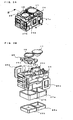
- FIG. 2 is a schematic perspective view showing the configuration of the objective lens actuator 21 of the embodiment.
- FIGS. 3A and 3B are diagrams for explaining the configuration of a lens holder 24 provided in the objective lens actuator 21 of the embodiment;
- FIG. 3A is a schematic perspective view showing the configuration of the lens holder 24, and
- FIG. 3B is an exploded perspective view showing the configuration of the lens holder 24.
- the objective lens actuator 21 mainly includes a base 22, permanent magnets 23a, 23b, the lens holder 24 and wires 29.
- the base 22 is made of a ferromagnetic metal, and has a through hole 22c formed approximately in the center to transmit a laser beam.
- the lens holder 24 to be described later in detail is disposed above the through hole 22c.
- a pair of permanent magnets 23a, 23b facing each other with a predetermined gap therebetween to hold the lens holder 24 are provided upright on the base 22.
- Each of the permanent magnets 23a, 23b has magnetic poles configured opposite to each other at a parting line BL as the boundary.
- the permanent magnet 23a and the permanent magnet 23b are arranged so that the same magnetic poles face each other.
- N poles face each other in front of the parting line BL in FIG. 2
- S poles face each other on the depth side to the parting line BL.
- projection pieces 22a, 22b formed bent from the base 22 are attracted.
- Two hold parts 24a, 24b are formed at the lens holder (first lens holder) 24 to be able to hold the first objective lens 17 and the second objective lens 18.
- the first objective lens 17 is directly bonded to the first hold part 24a by an adhesive to be held there.
- the second objective lens 18 is bonded and held by an adhesive to a tilt adjusting holder (second lens holder) 25 which is in turn bonded to the second hold part 24b by an adhesive to be held on the lens holder 24.
- the reason for mounting the second objective lens 18 on the lens holder 24 while being held on the tilt adjusting holder 25 is to ensure adjustment of a relative tilt between the first objective lens 17 and the second objective lens 18 without burden of cost and work at the time of assembling the objective lens actuator 21.
- the details on the relationship between the lens holder 24 and the tilt adjusting holder 25 will be given later.
- the embodiment is configured so that the second objective lens 18 alone is mounted on the tilt adjusting holder 25, it may be configured so that the first objective lens 17 is also mounted on the tilt adjusting holder 25. If tilting of just one of the objective lenses can be adjusted, a relative tilt between the objective lenses 17, 18 can be adjusted, so that it is sufficient that one of the objective lenses is held on the tilt adjusting holder 25.
- Tracking coils 26a, 26b are provided to face each other outside two of the side walls of the lens holder 24 which face the permanent magnets 23a, 23b.
- the tracking coils 26a, 26b are connected to generally be a single wire.
- a focus coil 27a and a focus coil 27b are provided side by side with the same height, inward of the lens holder 24 in such a way that the focus coil 27a surrounds the optical axis of the first objective lens 17 and the focus coil 27b surrounds the optical axis of the second objective lens 18.
- the focus coils 27a, 27b are connected to generally be a single wire.
- a tilt coil 28a and a tilt coil 28b are provided side by side with the same height, inward of the lens holder 24 and under the focus coils 27a, 27b in such a way that the tilt coil 28a surrounds the optical axis of the first objective lens 17 and the tilt coil 28b surrounds the optical axis of the second objective lens 18.
- the tilt coils 28a, 28b are connected to generally be a single wire.
- the thus configured lens holder 24 is slidably supported by a plurality of conductive wires 29 (three wires provided on each of the right and left sides) having one ends fixed to respective right and left side walls of the lens holder 24 (side walls where the tracking coils 26a, 26b are not provided).
- the other ends of the wires 29 are inserted in gel holes 30a of a gel holder 30 formed on the base 22, and are soldered to a printed circuit board (not shown) provided adjacent to the gel holder 30.
- the gel holder 30 serves to attenuate and suppress vibration occurring on each wire 29 by means of the gel material as the lens holder 24 is driven.
- the end portions of the individual conductive wires 29 that lie on the lens holder 24 side are arranged in such a way that the top two wires 29 are electrically connected to the tracking coils 26a, 26b by soldering, the middle two wires 29 are electrically connected to the focus coils 27a, 27b by soldering, and the bottom two wires 29 are electrically connected to the tilt coils 28a, 28b by soldering.
- the lens holder 24 is displaced in the tracking direction (same as the radial direction) by the electromagnetic action of the magnetic field generated by the permanent magnets 23a, 23b and the current flowing through the tracking coil 26a, 26b.
- the lens holder 24 is displaced in the focus direction by the electromagnetic action.
- the lens holder 24 is turned in a direction about the axis which is orthogonal to the focus direction and the tracking direction by the electromagnetic action.
- the permanent magnets 23a, 23b, the tracking coils 26a, 26b, the focus coils 27a, 27b, and the tilt coils 28a, 28b serve as a drive mechanism which drives the lens holder 24.
- the objective lens actuator 21 of the embodiment has two objective lenses 17, 18 in which case a relative tilt between the objective lenses 17, 18 needs to be reduced as much as possible.
- the objective lens actuator 21 of the embodiment is configured in such a way that as mentioned above, a relative tilt between the objective lenses 17, 18 can be adjusted by securely adhering the second objective lens 18 to the tilt adjusting holder 25 and adjusting the tilt of the tilt adjusting holder 25 with respect to the lens holder 24.
- FIG. 4 is a schematic cross-sectional view along line IV-IV in FIG. 3A .
- FIG. 5 is an enlarged view of a portion encircled by a dotted line in FIG. 4 .
- a slide part 25b is provided at that portion of the lower side of the tilt adjusting holder 25 which contacts the lens holder 24.
- the slide part 25b serves to ensure smooth tilt adjustment on the tilt adjusting holder 25 with respect to the lens holder 24, and is provided to have, for example, a curved surface. As the tilt adjusting holder 25 is slid with respect to the lens holder 24 by the slide part 25b, a relative tilt is adjusted.
- Projections 25a having an approximately rectangular cross section, which protrude toward the light incident side (corresponding to the lower side in FIG. 4 ) (which protrude toward the lens holder 24 with the tilt adjusting holder 25 mounted on the lens holder 24), are arranged outward of the slide part 25b and are formed at positions approximately symmetrical to each other with respect to a center axis 18a of the second objective lens 18 in the tilt adjusting holder 25.
- the projections 25a extend in a direction perpendicular to the surface of the sheet of FIG. 4 by a predetermined length (see FIG. 3B ).
- Grooves 31 are formed in the upper side of the lens holder 24.
- the grooves 31 are formed in such a way that the projections 25a of the tilt adjusting holder 25 are inserted in the grooves 31. Note that the projection 25a and the groove 31 have a relationship as shown in FIG. 5 .
- the relationship between a width t of the projection 25a and a width t' of the groove 31 becomes t ⁇ t', and a predetermined clearance CL is provided between the projection 25a and a bottom surface 31a of the groove 31. Designing the relationship between the projection 25a and the groove 31 this way inhibits the projection 25a and the groove 31 from coming in contact with each other, which would otherwise interfere with the sliding of the tilt adjusting holder 25, at the time the tilt adjusting holder 25 is slid with respect to the lens holder 24.
- the first objective lens 17 is securely adhered to the first hold part 24a of the lens holder 24 and is not moved as mentioned above.
- the second objective lens 18 is securely adhered to the tilt adjusting holder 25, so that its tilt is adjusted by moving the tilt adjusting holder 25.
- a UV adhesive adheresive to be cured by UV irradiation
- the tilt adjusting holder 25 is arranged at the second hold part 24b (see FIG. 3B ) of the lens holder 24.
- the relative tilt is adjusted while moving the tilt adjusting holder 25.
- the adjustment of a relative tilt between the objective lenses 17, 18 is carried out by a method of acquiring values on the tilts of the reflected lights at the rounded edges of the objective lenses 17, 18 by using, for example, a publicly-known laser auto collimator which measures the tilt of a measuring target in a non-contact manner, and determining that the tilts are the same when the values match with each other.
- the tilt adjusting holder 25 is formed of a material having a high UV transmissivity (e.g., polycarbonate or acrylic material).
- the adhesive to adhere the lens holder 24 and the tilt adjusting holder 25 together is filled in the grooves 31, so that the adhesive is unlike to run around to other portions than the adhesion portion.
- the adhesive layer can be made as thin as possible by adequately adjusting the widths of the projection 25a and the groove 31 and the clearance CL between the projection 25a and the groove 31 to set the amount of the adhesive 32 to be filled in the groove 31 to an adequate amount. Making the adhesive layer thin can reduce the amount of displacement of the set position of the tilt adjusting holder 25 caused by the influence of the temperature environment or the like. Further, the adhesion area can be increased depending on the design of the structure of the projection 25a and the groove 31. Therefore, the objective lens actuator 21 of the embodiment can make a relative tilt between the objective lenses 17, 18 as small as possible.
- a first adhesion portion 33 for adhering the second objective lens 18 and the tilt adjusting holder 25 together is structured so as not to overlie a second adhesion portion 34 (approximately corresponding to a position where the projection 25a of the tilt adjusting holder 25 which is adhered to the groove 31 of the lens holder 24 is provided) for adhering the tilt adjusting holder 25 and the lens holder 24 as seen from above.
- FIG. 6 is a schematic plan view of the tilt adjusting holder 25 as seen from above.
- FIG. 6 also shows the second objective lens 18.
- the configuration is not restrictive and can be modified in various forms without departing from the spirit and scope of the present invention.
- the configuration may be modified so that the projections 25a and the grooves 31 are so provided as to surround the second objective lens 18.
- the objective lens actuator is of a wire supporting type which is supported by wires.
- the present invention can be adapted to a variety of objective lens actuators which have a plurality of objective lenses and perform adjustment of a relative tilt between the objective lenses.
- the objective lens actuator may be modified to be of an axial slide type, and the locations and the number of objective lenses to be mounted on the objective lens actuator are not limited to those of the embodiment.
- optical pickup device having the objective lens actuator of the embodiment of the present invention is configured to be able to read and write information from and into a BD, DVD and CD
- the configuration is not restrictive and the invention can be adapted to a variety of optical pickup devices which use a plurality of objective lenses.
- the optical pickup device having the objective lens actuator of the invention mounted thereon can suppress occurrence of comatic aberration. Therefore, the invention is very useful.
Description
- The present invention relates to an objective lens actuator to be equipped in an optical pickup device which irradiates a light beam to an optical recording medium to enable recording and reading information, and, more particularly, to the configuration of an objective lens actuator having a plurality of objective lenses. The present invention also relates an optical pickup device having such an objective lens actuator.
- Optical recording mediums, such as a compact disc (hereinafter called "CD") and digital versatile disc (hereinafter called "DVD"), are popular. Further, studies have recently been made on enhancement of the density of optical recording mediums to increase the amount of information thereof, thereby putting optical recording mediums, such as HD-DVD and Blu-ray Disc (hereinafter called "BD"), which can record a huge amount of information to practical use.
- An optical pickup device is used in reading information from such an optical recording medium or writing information thereon. Depending on the type of the optical recording medium, it is necessary to change the numerical aperture (NA) of an objective lens used in an optical pickup device and the wavelength of a light source used therein. For example, an objective lens whose NA is 0.45 and a light source whose wavelength is 780 nm are used for a CD, an objective lens whose NA is 0.60 and a light source whose wavelength is 650 nm are used for a DVD, and an objective lens whose NA is 0.85 and a light source whose wavelength is 405 nm are used for a BD.
- Because the NA of an objective lens in use and the wavelength of a light source in use vary depending on the type of an optical recording medium, different optical pickup devices may be used for different optical recording mediums. It is however preferable that a single optical pickup device can compatibly use plural types of optical recording mediums, and multiple optical pickup devices of such a type have been developed. Some of such optical pickup devices have a plurality of objective lenses which can be switched from one to another depending on the type of an optical recording medium in use.
- An objective lens included in an optical pickup device is generally mounted on a lens holder provided in an objective lens actuator, so that the focus direction and tracking direction can be adjusted. The same is true of the optical pickup device that has a plurality of objective lenses, which however should be mounted on the lens holder in such a way that the objective lenses do not tilt with respect to one another (i.e., the center axes of the objective lenses become in parallel).
- The tilt angle of an objective lens actuator having a plurality of objective lenses is normally adjusted using a dominant one of the objective lenses for the optical pickup device so that the influence of comatic aberration or the like is reduced. At the time of, for example, adhering the objective lenses to the lens holder, however, the adhesion angle may be deviated, causing the objective lenses to tilt in relative to one another (relative tilt). In this case, when an objective lens which has not been used in adjusting the tilt angle of the objective lens actuator is used, comatic aberration occurs, bringing about a problem of degrading the quality of information read by the optical pickup device.
- In an objective lens actuator having a plurality of objective lenses, therefore, a relative tilt caused between the objective lenses needs to be suppressed. There is a conventional proposal on such a technique. For example,
JP-A-2005-174485 - However, the configuration disclosed in
JP-A-2005-174485 - As a solution to this problem, as shown in
FIG. 7A and FIG. 7B , anobjective lens 100 to be mounted on a lens holder 101 is configured to be mounted on atilt adjusting holder 102 which has a structure to facilitate tilt adjustment, thereby ensuring low-cost adjustment of a relative tilt with better workability. This configuration however has the following problem.FIGS. 7A and 7B are diagrams for explaining the configuration of a conventional objective lens actuator;FIG. 7A is a diagram showing the cross sections of a part of the lens holder 101 of the objective lens actuator, and thetilt adjusting holder 102 on which theobjective lens 100 is mounted, andFIG. 7B is an enlarged view of a portion encircled by a dotted line inFIG. 7A . - When adjustment of a relative tilt which is executed by moving the
tilt adjusting holder 102 is completed, thetilt adjusting holder 102 is securely adhered to the lens holder 101. In consideration of the workability or the like, normally, thetilt adjusting holder 102 is moved after a UV adhesive which is cured by UV irradiation is applied to a corresponding portion of thetilt adjusting holder 102 or the lens holder 101 (for example, a filled-in-black portion 103 inFIG. 7B ), not that an adhesive is supplied after the state of securing thetilt adjusting holder 102 is determined. Then, when adjustment of the relative tilt is completed, UV irradiation is performed to cure the adhesive, thereby securing thetilt adjusting holder 102. - In this case, the adhesive is likely to run around to other locations than an
adhesion portion 103 at the time of adjusting the relative tilt. Anadhesive 104 running around from theadhesion portion 103 has a certain thickness. When the temperature around the objective lens actuator changes, for example, thetilt adjusting holder 102 or the like is shifted from the set position due to the influence of thermal expansion or the like. In this case, the relative tilt between the objective lenses increases, thus reducing the reliability of the objective lens actuator. -
JP 10011765 A JP 10011765 claim 1. - In
JP 2006338811 A - In view of the above, it is an object of the present invention to provide a high-reliability objective lens actuator with a plurality of objective lenses, which can suppress a change in relative tilt between the objective lenses caused by adhesive fixation. It is another object of the present invention to provide an optical pickup device which has such an objective lens actuator to be able to reduce comatic aberration caused by a relative tilt between the objective lenses.
- To achieve the object, an objective lens actuator according to the present invention comprises a the features of
claim 1. - Accordingly, a relative tilt between the plurality of objective lenses of the objective lens actuator can be adjusted by using the tilt adjusting holder at the time of assembly. The objective lens actuator is configured in such a way that the lens holder and the tilt adjusting holder are adhered by using the projection provided at the tilt adjusting holder separately from the slide part and the groove formed in the lens holder, not by the slide part as achieved in the conventional art. This prevents the adhesive to adhere the tilt adjusting holder to the lens holder from running around to other portions than the adhesion portion. It is therefore possible to provide a high-reliability objective lens actuator which can suppress a change in relative tilt between the objective lenses caused by adhesive fixation.
- It is preferable that in the objective lens actuator with the configuration, the projection should be formed in an approximately symmetrical shape with respect to a center axis of the objective lens held by the tilt adjusting holder.
- Because the projection which is used at the time of adhering the tilt adjusting holder to the lens holder is formed in an approximately symmetrical shape with respect to the center axis of the objective lens held by the tilt adjusting holder, the tilt adjusting holder can be adhered, well balanced, to the lens holder.
- It is preferable that in the objective lens actuator with the configuration, a first adhesion portion for adhering the tilt adjusting holder and the objective lens held by the tilt adjusting holder together should not overlie a second adhesion portion for adhering the lens holder and the tilt adjusting holder together as seen from a side where the objective lens is arranged.
- Accordingly, in a case where the lens holder and the tilt adjusting holder are adhered together by using a UV adhesive which is cured by UV (ultraviolet radiation) irradiation, the amount of transmission of the UV is less likely to be reduced by the adhesion portion at which the tilt adjusting holder is adhered to the objective lens which is to be held by the tilt adjusting holder. This makes it possible to reliably adhere the lens holder and the tilt adjusting holder together.
- In the objective lens actuator with the configuration, the plurality of objective lenses may be two in number, and the at least one objective lens held by the tilt adjusting holder may be one in number.
- With this configuration, the number of objective lenses to be mounted on the objective lens actuator is not too large, so that the objective lens actuator can be realized easily. The configuration moves only one of the objective lenses at the time of adjusting a relative tilt between the objective lenses and is easy to achieve.
- An optical pickup device according to the present invention has an objective lens actuator with the foregoing configuration.
- Because the optical pickup device has an objective lens actuator with the foregoing configuration, it is possible to reduce comatic aberration caused by a relative tilt between the objective lenses, thus ensuring high-quality reproduction and recording.
-
-
FIG. 1 is a schematic plan view showing the configuration of one embodiment of an optical pickup device having an objective lens actuator according to the present invention; -
FIG. 2 is a schematic perspective view showing the configuration of the objective lens actuator according to the embodiment; -
FIG. 3A is a schematic perspective view showing the configuration of a lens holder provided in the objective lens actuator of the embodiment; -
FIG. 3B is an exploded perspective view of the lens holder shown inFIG. 3A ; -
FIG. 4 is a schematic cross-sectional view along line IV-IV inFIG. 3A ; -
FIG. 5 is an enlarged view of a portion encircled by a dotted line inFIG. 4 ; -
FIG. 6 is a schematic plan view of a tilt adjusting holder provided in the objective lens actuator of the embodiment as seen from above; -
FIG. 7A is a diagram for explaining the configuration of the conventional objective lens actuator and shows the cross sections of a part of the lens holder of the objective lens actuator, and the tilt adjusting holder on which an objective lens is mounted; and -
FIG. 7B is an enlarged view for explaining the configuration of the conventional objective lens actuator and shows a portion encircled by a dotted line inFIG. 7A . - A preferred embodiment of the present invention will be described below with reference to the accompanying drawings. The embodiment is just one illustrative example and is not restrictive.
- To begin with, the configuration of one embodiment of an
optical pickup device 1 which has an objective lens actuator according to the present invention.FIG. 1 is a schematic plan view showing the configuration of theoptical pickup device 1 of the embodiment.FIG. 1 shows those portions of the optical system of theoptical pickup device 1 which are generally covered and not seen for easier explanation of the optical system. - The
optical pickup device 1 of the embodiment is provided in such a way as to enable irradiation of a laser beam to three kinds (CD, DVD and BD) of optical discs (optical recording mediums) 50 to write and read information. Theoptical pickup device 1 is slidably supported on twoguide rails 2 disposed in an optical disc unit having theoptical pickup device 1. As the twoguide rails 2 are disposed in parallel to the direction of the radius (radial direction) of theoptical disc 50, theoptical pickup device 1 can be moved in the radial direction. - As shown in
FIG. 1 , the optical system of theoptical pickup device 1 includes afirst light source 11, a second light source 12, a dichroic prism 13, a collimator lens 14, abeam splitter 15, a risingmirror 16, a firstobjective lens 17, and a secondobjective lens 18. Other optical members, such as a wavefront aberration correcting element which corrects a wavefront aberration, are adequately disposed as needed. - The
first light source 11 is a single-wavelength laser diode that emits a laser beam with a wavelength of 405 nm which is used for BD. The second light source 12 is a two-wavelength laser diode that enables to switch laser beams of two kinds of wavelength and emits a laser beam with a wavelength of 650 nm which is used for DVD and a laser beam with a wavelength of 780 nm which is used for CD. The laser beams emitted from thefirst light source 11 and the second light source 12 are sent to the dichroic prism 13. - The dichroic prism 13 passes the laser beam emitted from the
first light source 11, and reflects the laser beam emitted from the second light source 12. The laser beam which has passed the dichroic prism 13 is sent to the collimator lens 14 to be converted to a parallel light. Thebeam splitter 15 reflects the laser beams emitted from thefirst light source 11 and the second light source 12 to guide the laser beam toward theoptical disc 50, and passes and guides reflected light from the recording surface (not shown) of theoptical disc 50 toward aphotodetector 20. - The laser beam emitted from the
first light source 11 or the second light source 12 and reflected by thebeam splitter 15 is reflected by the risingmirror 16 to travel in a direction perpendicular to the disc surface of the optical disc 50 (direction perpendicular to the surface of the sheet ofFIG. 1 ). The laser beam reflected by the risingmirror 16 is sent to the firstobjective lens 17 or the secondobjective lens 18. - The first
objective lens 17 and the secondobjective lens 18 both have a capability of condensing an input laser beam to the recording surface of theoptical disc 50, and are both mounted on anobjective lens actuator 21 which will be described in detail later. The firstobjective lens 17 is designed as an objective lens for BD, while the secondobjective lens 18 is designed as an objective lens for DVD and CD. The arrangement of the firstobjective lens 17 or the secondobjective lens 18 in the optical path is selectively switched according to the type of theoptical disc 50 in use. - In the embodiment, the switching between the first
objective lens 17 and the secondobjective lens 18 is carried out by moving theobjective lens actuator 21 in the radial direction with respect to anoptical pickup base 3 by moving means (not shown). It is to be noted however that the configuration to selectively use the twoobjective lenses - The reflected light reflected at the recording surface of the
optical disc 50 passes through the firstobjective lens 17 or the secondobjective lens 18, is reflected by the risingmirror 16, and passes through thebeam splitter 15. The reflected light having passed thebeam splitter 15 is condensed by acondenser lens 19 to be focused onto a light receiving area (not shown) of thephotodetector 20. - The
photodetector 20 serves to convert an optical signal received at the unillustrated light receiving area to an electric signal. The electric signal from thephotodetector 20 is processed to become a reproduction signal for reproducing information, a focus error signal or a tracking error signal for focus adjustment or tracking adjustment of theobjective lenses - Next, the general configuration of the
objective lens actuator 21 of the embodiment will be described referring toFIGS. 2 ,3A and3B .FIG. 2 is a schematic perspective view showing the configuration of theobjective lens actuator 21 of the embodiment.FIGS. 3A and 3B are diagrams for explaining the configuration of alens holder 24 provided in theobjective lens actuator 21 of the embodiment;FIG. 3A is a schematic perspective view showing the configuration of thelens holder 24, andFIG. 3B is an exploded perspective view showing the configuration of thelens holder 24. - The
objective lens actuator 21 mainly includes abase 22, permanent magnets 23a, 23b, thelens holder 24 andwires 29. - The
base 22 is made of a ferromagnetic metal, and has a through hole 22c formed approximately in the center to transmit a laser beam. Thelens holder 24 to be described later in detail is disposed above the through hole 22c. A pair of permanent magnets 23a, 23b facing each other with a predetermined gap therebetween to hold thelens holder 24 are provided upright on thebase 22. - Each of the permanent magnets 23a, 23b has magnetic poles configured opposite to each other at a parting line BL as the boundary. The permanent magnet 23a and the permanent magnet 23b are arranged so that the same magnetic poles face each other. For example, N poles face each other in front of the parting line BL in
FIG. 2 , and S poles face each other on the depth side to the parting line BL. At the outer surfaces of the permanent magnets 23a, 23b projection pieces 22a, 22b formed bent from the base 22 are attracted. - Two hold parts 24a, 24b are formed at the lens holder (first lens holder) 24 to be able to hold the first
objective lens 17 and the secondobjective lens 18. The firstobjective lens 17 is directly bonded to the first hold part 24a by an adhesive to be held there. The secondobjective lens 18 is bonded and held by an adhesive to a tilt adjusting holder (second lens holder) 25 which is in turn bonded to the second hold part 24b by an adhesive to be held on thelens holder 24. - The reason for mounting the second
objective lens 18 on thelens holder 24 while being held on thetilt adjusting holder 25 is to ensure adjustment of a relative tilt between the firstobjective lens 17 and the secondobjective lens 18 without burden of cost and work at the time of assembling theobjective lens actuator 21. The details on the relationship between thelens holder 24 and thetilt adjusting holder 25 will be given later. - Although the embodiment is configured so that the second
objective lens 18 alone is mounted on thetilt adjusting holder 25, it may be configured so that the firstobjective lens 17 is also mounted on thetilt adjusting holder 25. If tilting of just one of the objective lenses can be adjusted, a relative tilt between theobjective lenses tilt adjusting holder 25. - Tracking coils 26a, 26b are provided to face each other outside two of the side walls of the
lens holder 24 which face the permanent magnets 23a, 23b. The tracking coils 26a, 26b are connected to generally be a single wire. - A focus coil 27a and a focus coil 27b are provided side by side with the same height, inward of the
lens holder 24 in such a way that the focus coil 27a surrounds the optical axis of the firstobjective lens 17 and the focus coil 27b surrounds the optical axis of the secondobjective lens 18. The focus coils 27a, 27b are connected to generally be a single wire. - A tilt coil 28a and a tilt coil 28b are provided side by side with the same height, inward of the
lens holder 24 and under the focus coils 27a, 27b in such a way that the tilt coil 28a surrounds the optical axis of the firstobjective lens 17 and the tilt coil 28b surrounds the optical axis of the secondobjective lens 18. The tilt coils 28a, 28b are connected to generally be a single wire. - The thus configured
lens holder 24 is slidably supported by a plurality of conductive wires 29 (three wires provided on each of the right and left sides) having one ends fixed to respective right and left side walls of the lens holder 24 (side walls where the tracking coils 26a, 26b are not provided). The other ends of thewires 29 are inserted ingel holes 30a of agel holder 30 formed on thebase 22, and are soldered to a printed circuit board (not shown) provided adjacent to thegel holder 30. - With a gel material filled in the
gel holes 30a, thegel holder 30 serves to attenuate and suppress vibration occurring on eachwire 29 by means of the gel material as thelens holder 24 is driven. - The end portions of the individual
conductive wires 29 that lie on thelens holder 24 side are arranged in such a way that the top twowires 29 are electrically connected to the tracking coils 26a, 26b by soldering, the middle twowires 29 are electrically connected to the focus coils 27a, 27b by soldering, and the bottom twowires 29 are electrically connected to the tilt coils 28a, 28b by soldering. - Accordingly, as a current is supplied to the tracking coils 26a, 26b from the circuit board via the
wires 29 based on a signal generated from the tracking error signal, thelens holder 24 is displaced in the tracking direction (same as the radial direction) by the electromagnetic action of the magnetic field generated by the permanent magnets 23a, 23b and the current flowing through the tracking coil 26a, 26b. - Likewise, as a current is supplied to the focus coils 27a, 27b from the circuit board via the
wires 29 based on a signal generated from the focus error signal, thelens holder 24 is displaced in the focus direction by the electromagnetic action. As a current is supplied to the tilt coils 28a, 28b from the circuit board via thewires 29 based on a signal generated by a tilt sensor (not shown) provided in theoptical pickup device 1, thelens holder 24 is turned in a direction about the axis which is orthogonal to the focus direction and the tracking direction by the electromagnetic action. - That is, the permanent magnets 23a, 23b, the tracking coils 26a, 26b, the focus coils 27a, 27b, and the tilt coils 28a, 28b serve as a drive mechanism which drives the
lens holder 24. - The features of the
objective lens actuator 21 of the embodiment whose general configuration has been described above will be explained next. Theobjective lens actuator 21 has twoobjective lenses objective lenses objective lens actuator 21 of the embodiment is configured in such a way that as mentioned above, a relative tilt between theobjective lenses objective lens 18 to thetilt adjusting holder 25 and adjusting the tilt of thetilt adjusting holder 25 with respect to thelens holder 24. - As mentioned above, conventionally, the adhesive runs around at the time of adjusting a relative tilt by the
tilt adjusting holder 25, thereby deviating the relative tilt that has been adjusted after adhesive fixation. Theobjective lens actuator 21 of the embodiment is therefore configured so as to be able to prevent the adhesive from running around. This configuration will be described referring toFIGS. 4 and 5. FIG. 4 is a schematic cross-sectional view along line IV-IV inFIG. 3A .FIG. 5 is an enlarged view of a portion encircled by a dotted line inFIG. 4 . - As shown in
FIG. 4 , a slide part 25b is provided at that portion of the lower side of thetilt adjusting holder 25 which contacts thelens holder 24. The slide part 25b serves to ensure smooth tilt adjustment on thetilt adjusting holder 25 with respect to thelens holder 24, and is provided to have, for example, a curved surface. As thetilt adjusting holder 25 is slid with respect to thelens holder 24 by the slide part 25b, a relative tilt is adjusted. - Projections 25a having an approximately rectangular cross section, which protrude toward the light incident side (corresponding to the lower side in
FIG. 4 ) (which protrude toward thelens holder 24 with thetilt adjusting holder 25 mounted on the lens holder 24), are arranged outward of the slide part 25b and are formed at positions approximately symmetrical to each other with respect to a center axis 18a of the secondobjective lens 18 in thetilt adjusting holder 25. The projections 25a extend in a direction perpendicular to the surface of the sheet ofFIG. 4 by a predetermined length (seeFIG. 3B ). - Grooves 31 (see
FIG. 3B ) are formed in the upper side of thelens holder 24. Thegrooves 31 are formed in such a way that the projections 25a of thetilt adjusting holder 25 are inserted in thegrooves 31. Note that the projection 25a and thegroove 31 have a relationship as shown inFIG. 5 . - Specifically, the relationship between a width t of the projection 25a and a width t' of the
groove 31 becomes t<t', and a predetermined clearance CL is provided between the projection 25a and a bottom surface 31a of thegroove 31. Designing the relationship between the projection 25a and thegroove 31 this way inhibits the projection 25a and thegroove 31 from coming in contact with each other, which would otherwise interfere with the sliding of thetilt adjusting holder 25, at the time thetilt adjusting holder 25 is slid with respect to thelens holder 24. - A description will now be given of the action of the
objective lens actuator 21 of the embodiment with the foregoing configuration while explaining procedures of adjusting a relative tilt between the firstobjective lens 17 and the secondobjective lens 18. - At the time of adjusting a relative tilt between the objective lenses, the first
objective lens 17 is securely adhered to the first hold part 24a of thelens holder 24 and is not moved as mentioned above. The secondobjective lens 18 is securely adhered to thetilt adjusting holder 25, so that its tilt is adjusted by moving thetilt adjusting holder 25. Before the adjustment of the relative tilt by thetilt adjusting holder 25, a UV adhesive (adhesive to be cured by UV irradiation) is injected in thegrooves 31 of thelens holder 24 by a predetermined amount and thetilt adjusting holder 25 is arranged at the second hold part 24b (seeFIG. 3B ) of thelens holder 24. - In this state, the relative tilt is adjusted while moving the
tilt adjusting holder 25. The adjustment of a relative tilt between theobjective lenses objective lenses - When the adjustment of a relative tilt between the
objective lenses grooves 31 from the top surface side, curing the UV adhesive 32 so that thetilt adjusting holder 25 is secured to thelens holder 24. Thetilt adjusting holder 25 is formed of a material having a high UV transmissivity (e.g., polycarbonate or acrylic material). - As described above, the adhesive to adhere the
lens holder 24 and thetilt adjusting holder 25 together is filled in thegrooves 31, so that the adhesive is unlike to run around to other portions than the adhesion portion. The adhesive layer can be made as thin as possible by adequately adjusting the widths of the projection 25a and thegroove 31 and the clearance CL between the projection 25a and thegroove 31 to set the amount of the adhesive 32 to be filled in thegroove 31 to an adequate amount. Making the adhesive layer thin can reduce the amount of displacement of the set position of thetilt adjusting holder 25 caused by the influence of the temperature environment or the like. Further, the adhesion area can be increased depending on the design of the structure of the projection 25a and thegroove 31. Therefore, theobjective lens actuator 21 of the embodiment can make a relative tilt between theobjective lenses - In the
objective lens actuator 21, as shown inFIG 6 , afirst adhesion portion 33 for adhering the secondobjective lens 18 and thetilt adjusting holder 25 together is structured so as not to overlie a second adhesion portion 34 (approximately corresponding to a position where the projection 25a of thetilt adjusting holder 25 which is adhered to thegroove 31 of thelens holder 24 is provided) for adhering thetilt adjusting holder 25 and thelens holder 24 as seen from above.FIG. 6 is a schematic plan view of thetilt adjusting holder 25 as seen from above.FIG. 6 also shows the secondobjective lens 18. - With this configuration, when the
lens holder 24 and thetilt adjusting holder 25 are securely adhered by UV irradiation, the UV transmissivity does not become lower even with the presence of thefirst adhesion portion 33, thus preventing insufficient adhesion between thelens holder 24 and thetilt adjusting holder 25. - Although the above-described embodiment is configured so that the
grooves 31 of thelens holder 24 and the projections 25a of thetilt adjusting holder 25 are each provided two in number at approximately symmetrical positions with the center axis 18a of the secondobjective lens 18 in between, the configuration is not restrictive and can be modified in various forms without departing from the spirit and scope of the present invention. For example, the configuration may be modified so that the projections 25a and thegrooves 31 are so provided as to surround the secondobjective lens 18. - In the above-described embodiment, the objective lens actuator is of a wire supporting type which is supported by wires. However, the present invention can be adapted to a variety of objective lens actuators which have a plurality of objective lenses and perform adjustment of a relative tilt between the objective lenses. For example, the objective lens actuator may be modified to be of an axial slide type, and the locations and the number of objective lenses to be mounted on the objective lens actuator are not limited to those of the embodiment.
- Although the optical pickup device having the objective lens actuator of the embodiment of the present invention is configured to be able to read and write information from and into a BD, DVD and CD, the configuration is not restrictive and the invention can be adapted to a variety of optical pickup devices which use a plurality of objective lenses.
- According to the present invention, in the objective lens actuator having a plurality of objective lenses mounted thereon, a relative tilt between the objective lenses can be reduced as small as possible. Accordingly, the optical pickup device having the objective lens actuator of the invention mounted thereon can suppress occurrence of comatic aberration. Therefore, the invention is very useful.
Claims (5)
- An objective lens actuator comprising:a plurality of objective lenses (17, 18);a lens holder (24) on which the plurality of objective lenses (17, 18) are mounted;a tilt adjusting holder (25) having a slide part (25b), the slide part (25b) sliding the tilt adjusting holder (25) with respect to the lens holder (24) at a time of assembly, anda drive mechanism (23, 26, 27, 28, 29) that drives the lens holder (24),wherein at least one of the plurality of objective lenses (17, 18) is mounted on the lens holder (24) while being held by the tilt adjusting holder (25), characterized in thatthe tilt adjusting holder (25) has a projection (25a) formed thereon, the projection (25a) being arranged outward of the slide part (25b) and protruding towards the lens holder (24) with the tilt adjusting holder (25) being mounted on the lens holder (24), andthe lens holder (24) has a groove (31) formed therein where the projection (25a) is securely adhered.
- The objective lens actuator according to claim 1, wherein the projection (25a) is formed in an approximately symmetrical shape with respect to a center axis of the objective lens (17, 18) held by the tilt adjusting holder (25).
- The objective lens actuator according to claim 1 or 2, wherein a first adhesion portion (33) for adhering the tilt adjusting holder (25) and the objective lens (17, 18) held by the tilt adjusting holder (25) together does not overlie a second adhesion portion (34) for adhering the lens holder (24) and the tilt adjusting holder (25) together as seen from a side where the objective lens (17, 18) is arranged.
- The objective lens actuator according to any one of claims 1 to 3, wherein the plurality of objective lenses (17, 18) are two in number, and the at least one objective lens (17, 18) held by the tilt adjusting holder (25) is one in number.
- An optical pickup device having an objective lens actuator as recited in any one of claims 1 to 4.
Applications Claiming Priority (1)
| Application Number | Priority Date | Filing Date | Title |
|---|---|---|---|
| JP2007010983A JP2008176887A (en) | 2007-01-22 | 2007-01-22 | Objective lens actuator and optical pickup device including the same |
Publications (2)
| Publication Number | Publication Date |
|---|---|
| EP1950751A1 EP1950751A1 (en) | 2008-07-30 |
| EP1950751B1 true EP1950751B1 (en) | 2009-07-15 |
Family
ID=39307940
Family Applications (1)
| Application Number | Title | Priority Date | Filing Date |
|---|---|---|---|
| EP08000928A Expired - Fee Related EP1950751B1 (en) | 2007-01-22 | 2008-01-18 | Objective lens actuator and optical pickup device having the same |
Country Status (4)
| Country | Link |
|---|---|
| US (1) | US8254219B2 (en) |
| EP (1) | EP1950751B1 (en) |
| JP (1) | JP2008176887A (en) |
| DE (1) | DE602008000044D1 (en) |
Families Citing this family (2)
| Publication number | Priority date | Publication date | Assignee | Title |
|---|---|---|---|---|
| JP2013131270A (en) | 2011-12-21 | 2013-07-04 | Hitachi Media Electoronics Co Ltd | Optical pickup device and method for manufacturing the same |
| DE102022209222A1 (en) | 2022-09-06 | 2024-03-07 | Robert Bosch Gesellschaft mit beschränkter Haftung | Optical assembly and method for joining an optical assembly |
Family Cites Families (15)
| Publication number | Priority date | Publication date | Assignee | Title |
|---|---|---|---|---|
| JPH05101429A (en) * | 1991-10-08 | 1993-04-23 | Seiko Epson Corp | Optical head |
| US5453962A (en) * | 1992-08-20 | 1995-09-26 | Mitsubishi Denki Kabushiki Kaisha | Focus error detecting device |
| JP3508005B2 (en) | 1996-06-26 | 2004-03-22 | シャープ株式会社 | Optical disc apparatus and method for adjusting tilt of objective lens thereof |
| KR100298825B1 (en) * | 1996-08-19 | 2001-10-26 | 하시모토 야스고로 | Object lens driving apparatus and photo-disk apparatus using thereof |
| JP2001160229A (en) * | 1999-12-02 | 2001-06-12 | Sankyo Seiki Mfg Co Ltd | Optical head device and method for regulating inclination angle of its objective lens |
| JP2003066300A (en) * | 2001-08-29 | 2003-03-05 | Sony Corp | Device for manufacturing objective lens and method for manufacturing objective lens |
| JP3854588B2 (en) * | 2003-05-15 | 2006-12-06 | シャープ株式会社 | Optical pickup device |
| JP2005174485A (en) | 2003-12-12 | 2005-06-30 | Matsushita Electric Ind Co Ltd | Objective lens, optical pick-up device, and optical disk device |
| US7301864B2 (en) * | 2003-07-07 | 2007-11-27 | Matsushita Electric Industrial Co., Ltd. | Objective lens, optical pick-up device, and optical disk device |
| KR100612014B1 (en) * | 2004-06-29 | 2006-08-11 | 삼성전자주식회사 | Optical pickup and apparatus and method for assembling lenses |
| JP4480495B2 (en) * | 2004-07-07 | 2010-06-16 | 三洋電機株式会社 | Optical pickup device |
| CN100463061C (en) * | 2004-07-21 | 2009-02-18 | 柯尼卡美能达精密光学株式会社 | Assembly method of optical pickup apparatus and optical pickup apparatus |
| US20060028935A1 (en) * | 2004-08-03 | 2006-02-09 | Matsushita Electric Industrial Co., Ltd. | Optical pickup device, optical disk apparatus, and light-receiving unit |
| JP4682653B2 (en) * | 2005-03-14 | 2011-05-11 | ミツミ電機株式会社 | Autofocus actuator |
| JP2006338811A (en) | 2005-06-03 | 2006-12-14 | Matsushita Electric Ind Co Ltd | Optical pickup and its adjusting device |
-
2007
- 2007-01-22 JP JP2007010983A patent/JP2008176887A/en active Pending
-
2008
- 2008-01-18 EP EP08000928A patent/EP1950751B1/en not_active Expired - Fee Related
- 2008-01-18 DE DE602008000044T patent/DE602008000044D1/en active Active
- 2008-01-22 US US12/010,213 patent/US8254219B2/en not_active Expired - Fee Related
Also Published As
| Publication number | Publication date |
|---|---|
| US20080181087A1 (en) | 2008-07-31 |
| DE602008000044D1 (en) | 2009-08-27 |
| JP2008176887A (en) | 2008-07-31 |
| US8254219B2 (en) | 2012-08-28 |
| EP1950751A1 (en) | 2008-07-30 |
Similar Documents
| Publication | Publication Date | Title |
|---|---|---|
| US7562372B2 (en) | Optical pickup | |
| KR20060047382A (en) | Objective lens driver | |
| KR20060051246A (en) | Optical pickup and disc drive apparatus | |
| KR101222860B1 (en) | Optical pickup device | |
| US20040130999A1 (en) | Actuator for optical pickup, optical pickup apparatus, and optical recording/reproducing apparatus using same | |
| EP1950751B1 (en) | Objective lens actuator and optical pickup device having the same | |
| US20070183294A1 (en) | Objective lens driving unit and optical pickup device having the same | |
| JP4227295B2 (en) | Optical pickup device and optical component storage module for optical pickup | |
| EP1909271B1 (en) | Optical pickup actuator capable of preventing adhesive agent in supporting portions of a damper base from deteriorating in strength | |
| JP4509854B2 (en) | Objective lens driving device, optical pickup device and optical disk device | |
| US8938746B2 (en) | Object lens driving device and optical disc drive including the same | |
| JP3624624B2 (en) | Optical pickup and disc player | |
| US7924688B2 (en) | Optical pickup and manufacturing method for optical pickup | |
| JP4607068B2 (en) | Optical pickup | |
| KR20080029744A (en) | Optical pickup | |
| EP1965379A1 (en) | Objective lens actuator and optical pickup device including the same | |
| JP2009015934A (en) | Lens holder for optical pickup and optical pickup having same | |
| US20080151708A1 (en) | Objective lens driving device, assembling method for the same and optical disc apparatus | |
| JP2009146531A (en) | Lens holder for optical pickup and optical pickup provided with the same | |
| JP2000020982A (en) | Two-lens optical head device, and disk recording or reproducing apparatus | |
| JP2007184064A (en) | Optical pickup device | |
| JP2007213694A (en) | Optical pickup device | |
| JP2009076179A (en) | Lens holder for optical pickup, and optical pickup comprising the same | |
| JP2008084508A (en) | Optical pickup | |
| JP2012230745A (en) | Optical pickup device |
Legal Events
| Date | Code | Title | Description |
|---|---|---|---|
| PUAI | Public reference made under article 153(3) epc to a published international application that has entered the european phase |
Free format text: ORIGINAL CODE: 0009012 |
|
| AK | Designated contracting states |
Kind code of ref document: A1 Designated state(s): AT BE BG CH CY CZ DE DK EE ES FI FR GB GR HR HU IE IS IT LI LT LU LV MC MT NL NO PL PT RO SE SI SK TR |
|
| AX | Request for extension of the european patent |
Extension state: AL BA MK RS |
|
| 17P | Request for examination filed |
Effective date: 20080811 |
|
| GRAP | Despatch of communication of intention to grant a patent |
Free format text: ORIGINAL CODE: EPIDOSNIGR1 |
|
| AKX | Designation fees paid |
Designated state(s): DE FR GB |
|
| GRAS | Grant fee paid |
Free format text: ORIGINAL CODE: EPIDOSNIGR3 |
|
| GRAA | (expected) grant |
Free format text: ORIGINAL CODE: 0009210 |
|
| AK | Designated contracting states |
Kind code of ref document: B1 Designated state(s): DE FR GB |
|
| REG | Reference to a national code |
Ref country code: GB Ref legal event code: FG4D |
|
| REF | Corresponds to: |
Ref document number: 602008000044 Country of ref document: DE Date of ref document: 20090827 Kind code of ref document: P |
|
| PLBE | No opposition filed within time limit |
Free format text: ORIGINAL CODE: 0009261 |
|
| STAA | Information on the status of an ep patent application or granted ep patent |
Free format text: STATUS: NO OPPOSITION FILED WITHIN TIME LIMIT |
|
| 26N | No opposition filed |
Effective date: 20100416 |
|
| REG | Reference to a national code |
Ref country code: FR Ref legal event code: PLFP Year of fee payment: 8 |
|
| PGFP | Annual fee paid to national office [announced via postgrant information from national office to epo] |
Ref country code: DE Payment date: 20150113 Year of fee payment: 8 |
|
| PGFP | Annual fee paid to national office [announced via postgrant information from national office to epo] |
Ref country code: GB Payment date: 20150114 Year of fee payment: 8 Ref country code: FR Payment date: 20150108 Year of fee payment: 8 |
|
| REG | Reference to a national code |
Ref country code: DE Ref legal event code: R119 Ref document number: 602008000044 Country of ref document: DE |
|
| GBPC | Gb: european patent ceased through non-payment of renewal fee |
Effective date: 20160118 |
|
| REG | Reference to a national code |
Ref country code: FR Ref legal event code: ST Effective date: 20160930 |
|
| PG25 | Lapsed in a contracting state [announced via postgrant information from national office to epo] |
Ref country code: DE Free format text: LAPSE BECAUSE OF NON-PAYMENT OF DUE FEES Effective date: 20160802 Ref country code: GB Free format text: LAPSE BECAUSE OF NON-PAYMENT OF DUE FEES Effective date: 20160118 |
|
| PG25 | Lapsed in a contracting state [announced via postgrant information from national office to epo] |
Ref country code: FR Free format text: LAPSE BECAUSE OF NON-PAYMENT OF DUE FEES Effective date: 20160201 |