EP2000931A1 - System und Verfahren zur Erzeugung eines Objektmodells - Google Patents
System und Verfahren zur Erzeugung eines Objektmodells Download PDFInfo
- Publication number
- EP2000931A1 EP2000931A1 EP08251827A EP08251827A EP2000931A1 EP 2000931 A1 EP2000931 A1 EP 2000931A1 EP 08251827 A EP08251827 A EP 08251827A EP 08251827 A EP08251827 A EP 08251827A EP 2000931 A1 EP2000931 A1 EP 2000931A1
- Authority
- EP
- European Patent Office
- Prior art keywords
- cycles
- time
- composite
- database
- module
- Prior art date
- Legal status (The legal status is an assumption and is not a legal conclusion. Google has not performed a legal analysis and makes no representation as to the accuracy of the status listed.)
- Withdrawn
Links
Images




Classifications
-
- G—PHYSICS
- G06—COMPUTING OR CALCULATING; COUNTING
- G06F—ELECTRIC DIGITAL DATA PROCESSING
- G06F16/00—Information retrieval; Database structures therefor; File system structures therefor
- G06F16/20—Information retrieval; Database structures therefor; File system structures therefor of structured data, e.g. relational data
- G06F16/28—Databases characterised by their database models, e.g. relational or object models
- G06F16/284—Relational databases
- G06F16/288—Entity relationship models
Definitions
- the present disclosure relates to the creation of object models. More specifically, the present disclosure relates to the creation of dynamic software models of real world entities, while allowing for lossless processing and reversible changes in the entities, as well as in the characteristics and history of the entities.
- object-oriented systems have classes for describing the different types of real-world entities and their associated attributes and methods.
- the classes model the entities, so a change in the entity leads to a change in the code. This requires a programmer to create an entirely new version of the software application.
- Most object-oriented languages structure a program as a set of classes. A class defines the structure and behavior of objects. Thus, a new class is generally needed for each new kind of object that is encountered. For large and complex systems, this leads to the problem of having a class in which an unknown number of subclasses must be formed.
- a method for creating a dynamic domain model of an object comprises storing and organizing temporal information about the object in a bitemporal database that includes both a valid time and a transaction time for the information.
- the information is inserted into a plurality of tables in the database and a key is assigned to each of the plurality of tables.
- a composite representing the object is formed to represent a state of the object at the current time or at any previous time by dynamically linking the information by key, based on a logic and a request made by a user.
- a system for creating a dynamic domain model of an object includes a bitemporal database storing temporal information about the object, a relational database management system managing the bitemporal database, an object relational mapper, and a logic component.
- the database includes both a valid time and a transaction time for the information.
- the object relational mapper converts the information in the database into a composite representing the object, and the composite is formed by dynamically linking tables within the database based on relationships defined by the logic component.
- the composite represents a state of the object at the current time or any previous time.
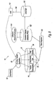
- System 10 creates an object model or domain model 12.
- Domain model 12 typically represents an abstraction of a physical, real world object. Domain model 12 contains information about various entities or subassemblies of the real world object, as well as information about the relationships between the entities.
- System 10 includes a logic component 14, which defines the relationships between entities within domain model 12.
- System 10 also includes an object-relational mapper 16, data model 18, and relational database management system (DBMS) 20. Relational DBMS 20 manages data model 18, and object-relational mapper converts data contained within data model 18 into domain model 12.
- domain model 12 represents an aircraft engine.
- Domain model 12 includes a flexible and dynamic semantic structure allowing for extensible software representations of objects, characteristics, and attributes, while providing a basis for maintaining a history of the manipulation of the objects, characteristics, and attributes over time.
- system 10 implements a method for processing, tracking, and calculating information regarding an object of interest where the representative structure of the object, characteristics of the structure, and the temporal history of both the structure and the characteristics of its components may be easily tracked and modified over time. System 10 is therefore able to rematerialize the representative state of the object at an arbitrary time in the past.
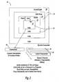
- FIG. 2 illustrates a dynamic composite 22, which is a component of domain model 12.
- Domain model 12 may have a single composite 22 or may be made up of a plurality of composites 22.
- Domain model 12 represents a real world object, or some other object of interest, and composite 22 represents an arbitrarily complex assembly of the object.
- Composite 22 is made up of individual entities 24.
- a generic entity-relationship model is established within composite 22, and the composite provides an arbitrarily wide and arbitrarily deep composition as a principal organizational mechanism.
- domain model 12 of FIG. 1 includes a composite representing an aircraft engine.
- an arbitrary relationship as defined by logic component 14, can be established between arbitrary entities as follows: an engine 26 contains build groups 28, which contain modules 30, which contain parts 32.
- Composite 22 provides for bidirectional and recursive relationships. Any entity 24 in the composite can find its child or parent entity, and any composite 22 can contain other composites. Composite 22 can therefore represent notions of inheritance ("is a"), ownership ("owns"), containment ("has a”), as well as composition ("part of”).
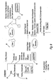
- FIG. 3 illustrates the core structure of domain model 12. As seen in FIG. 3 , relationships between objects are represented as data. For example, an attribute type object 38 and an entity type object 40 are connected by an association object 42.
- system 10 implements a mirrored generic data model coupled with a mirrored generic domain model.
- the mirrored models can impose an overarching relationship on composite 22, which is an arbitrary subset of information.
- the mirrored models organize temporal information and processing into a bitemporal database.
- a bitemporal database is a database that includes both valid time and transaction time of the data it contains. Facts are stored in the bitemporal database at a point in time. After the fact is stored, it can be retrieved. The time when a fact is stored in the database is the transaction time of the fact. Transaction times are consistent with the serial order of the transactions. Transaction times cannot be changed. A transaction time also cannot be later than the current time. Typically, the commit time of a database transaction is used as the transaction time.
- each entity 24 of composite 22 can also include characteristics 34.
- Characteristic 34 can include an attribute 36.
- Attribute 36 can be used to associate historical information with characteristic 34, and thus by relationship, entity 24 and composite 22.
- the characteristic/attribute mechanism can be used to "decorate" any specific entity 24 or composite 22 any number of times.
- FIG. 4 illustrates the relationships between tables in data model 18.
- a table 44 representing an entity 24 will include at least three fields: entity type 46, hierarchy type 48, and last upload effective date 50.
- An entity 24 may have several attributes, as identified in attribute table 52. However, an attribute will be associated with only one attribute type 53.
- an entity 24 may have several tracked characteristics or attributes 36, represented by table 54 and having a characteristic type represented by table 55.
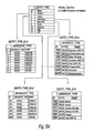
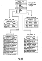
- FIGS. 5A and 5B show an embodiment of tables within database 20 of system 10 where system 10 is used for tracking the configuration and utilization of an aircraft engine.
- Each entity 24 represented by the data model 18 includes entity type 46 and hierarchy type 48.
- the values for entity type 46 and hierarchy type 48 are determined by logic component 14.
- any number of entity types can be defined, including airframe, engine, build group, major part, family, subfamily, Line Replaceable Unit (LRU), and Life Limited Part (LLP).
- LRU Line Replaceable Unit
- LLP Life Limited Part
- Each entity type is assigned a name and a unique entity type ID number. ID numbers are used as keys to associate one table with one or more other tables.
- Hierarchy types are defined as subsets of each entity type. For example, subsets of the engine entity type could include hierarchy types representing different models of engines.
- FIGS. 6 and 7 illustrate the relationships between entities.
- FIG. 6 shows three entities: an airframe and two engines in first and second positions associated with the airframe.
- Each entity table includes a field for ID number, entity type ID number, hierarchy type ID number, and a value for last update effective date.
- the entity table is linked to an entity structure table that identifies the parent entity (the airframe) as well as the position of the entity (first position on the airframe).
- the entity structure is also associated with a hierarchy type which is in turn associated with an entity type.
- FIG. 7 illustrates an example of an entity and its associated tracked characteristic.
- the entity table includes fields for ID number, entity type ID number, hierarchy type ID number, and last update effective date.
- the entity tab!e is linked to the entity type table through the entity type ID number, and is linked to a tracked characteristic table through the entity ID number.
- the tracked characteristic table includes an entity ID field and a characteristic ID field.
- the entity ID field matches the ID number contained within the entity table and links the tracked characteristic table to the entity structure table.
- the characteristic ID field links the tracked characteristic table to the characteristic type table.
- the characteristic type table includes the data that drives utilization processing. For example, for a life limited part in an aircraft engine such as a first stage fan disk, the characteristic type may include total time in operation.
- Domain models 12 built by system 10 have a flexible and dynamic semantic structure that is orthogonal to the referential integrity of the underlying persistence mechanism.
- domain models 12 can be built with a minimal representation in terms of stored information that can be expanded and altered over time, with the preservation of relevant history.
- Relations maintained in the domain model 12 are found dynamically via search, and therefore they do not coerce the compositional structure, or characteristics of the structure's components.
- Temporal relations are maintained in a bitemporal fashion, and therefore reasoning about time and events in relation to the modeled structures can be undertaken for arbitrary points in time. Additionally, cases of incomplete temporal or spatial data are handled as natural model states, subject only to the rules as defined by logic component 14 of system 10.
- a bitemporal database is built from the combination of domain model 12 and the structuring of entities within composites 22 that comprise domain model 12 and the ability to track the history of each entity and its characteristics in an arbitrary fashion.
- System 10 also records errors and provides an audit trail using system framework logic.
- Logic component 14 of system 10 may not allow certain classes of errors, such as an erroneous edit, to persist. However, because of the issues related to erroneous, missing, or out of sequence data, the system might consider data as being valid (the valid time is accepted as being true at the time of a transaction), but later system 10 can consider new inputs that may augment or even invalidate previous data. Therefore, the complete history of these changes and the original values being replaced may all be kept so that they are available for reprocessing.
- the mirrored data and domain models allow information to be stored in a relational database but to be realized as Object Oriented structures in memory.
- the object structures are built as Plain Old Java Objects (POJOs).
- POJOs Plain Old Java Objects
- This architecture allows full use of the power of the underlying relational database technology to provide relational operations (project, intersect, etc.) upon the data sets.
- the POJO-based object model allows the full use of the powerful capabilities of a modern Object Oriented language such as Java TM to implement algorithms and the logic.
- An object relational mapping layer maintains a consistent mapping between the models.
- the combination of the mirrored models and the mapping layer provides the foundation necessary to implement the bitemporal database functionality. Attributes such as recorded date, to date, and from date, as evidence in the tracked characteristics table are used to persist temporal information.
- the entity structure table contains "begin date” and "end date” attributes, as well as keyed attributes for parent and child entity IDs and hierarchy type IDs. This is how elements of composites 22 are related spatially, while maintaining the time interval endpoints that allow the re-creation of composites 22 as they existed during a prior time interval.
- the specialized form of attribute (tracked characteristic) 36 can hold time-varying streams for characteristic 34.
- Characteristic 34 may be applied to any entity 24 within composite 22. Characteristic 34 can represent dynamic characteristics or static characteristics. Rather than relying on a fixed index/time relationship, characteristic 34 can represent time series, as well as slowly changing data that carries its own timestamp. Entities 24 may stand alone, or the entities may be combined into composites 22.
- system 10 is extremely flexible, because composites 22, as well as the entities 24 that make up the composites, can be completely arbitrary in structure.
- the structure of composite 22 can comprise many levels or no levels at all, depending on the available information for a given object being represented. System 10 allows an object to be modeled using as many or as few structural levels as desired.
- system 10 forms a part of an On-Wing Tracker (OWT) application of an Advanced Diagnostics and Engine management System. As part of the OWT application, system 10 calculates the utilization of a particular configuration of a given engine at a particular time.
- OBT On-Wing Tracker
- Typical utilization characteristics that can be tracked and calculated by system 10 include the following: • Time Delta • Time Since Last Maintenance • Cycles Delta • Cycles Since Last Maintenance • Starts Delta • Time Since Overhaul • Flight Hours Delta • Cycles Since Overhaul • N1 Cycles Delta • Time Since Bench Test • Total Time • Cycles Since Bench Test • Total Cycles • Times Repaired • Time Since Last Visit • De-rate • Cycles Since Last Visit • Average Ambient Temperature • Time Since Repair • Total Module Flight Hours • Cycles Since Repair • Total Module Starts • Module Starts Since Heavy Maintenance • Part Starts Since Inspection • Part Starts Since Repair • Module Starts Since Last Repair • Component Starts Since Bench Check • Module Starts Since Last Visit • Module Starts Since Performance Restoration • Part Starts Since Overhaul • Part Total Starts • Module Flight Hours Since Heavy Maintenance • Part Flight Hours Since Inspection • Module Flight Hours Since Last Visit • Part Flight Hours Since Repair • Component Flight Hours Since Bench Check • Module Flight Hours Since Performance Restoration • Part Flight Hours Since Overhaul • Module Flight Hours Since Repair • Part Total Flight
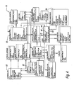
- FIG. 8 illustrates an embodiment of system 10 incorporating the On-Wing Tracker for an aircraft engine.
- an administrator 92 can load data, retrieve and modify existing data, add new entities 24, or change configurations by "moving" entities 24 to indicate that the entities 24 are installed in different composites 22.
- OWT application 90 inserts and/or updates the results of these interactions principally into three schema tables within database 18: tracked characteristic table 94, characteristic type table 96, and entity structure table 98.
- Tracked characteristic table 94 contains the actual tracked data for characteristic 34, including utilization data and non-utilization data.
- Characteristic type table is a reference table describing characteristics 34.
- Entity structure table 98 defines pair-wise installation of an entity (child) within another entity (parent) and the time span of this installation. Expanding the table for a given point of time forms the entire configuration at that time.
- Any change, such as an insertion, update, or deletion, made to tables 94, 96, 98 is added in real-time to the counterpart table in a change-data-capture schema, and the changes are sent to a data integrator 100.
- Data integrator 100 copies the changes to populate an input table stored in persistent staging database (PSD) 102.
- PSD persistent staging database
- Utilization extractor/calculator 104 uses the data stored in the PSD to compute the allocation of the changes that have been inputted. This calculation process is an analog of the processing that occurs when an end user materializes the information for specific entities by interacting directly with system 10 using OWT application 90.
- Calculator 104 writes its output into a work table in PSD 102 that specifies the accumulative value for each requested entity, characteristic, and time.
- An internal process then stores the results in a PSD history table. Thereafter, a separate workflow uses that data to populate a utilization fact table within a data mart 106. A user 110 can then use reporting tool 108 to access the configuration and utilization data within data mart 106 via reports and queries.
- system 10 calculates the utilization of entities 24 that make up composite 22.
- system 10 must represent a variety of information concerning entities 24 and characteristics 34 in domain model 12. This information may also include historical information and/or values regarding entities 24.
- a user of system 10 may choose to represent different types of physical assemblies. The user may also choose to model and track only a subset of entities 24 that make up composite 22. For example, for a given aircraft engine, a user may choose to model and track only the low pressure compressor and its associated subassemblies. Occasionally, the information concerning entities 24 may be missing, or erroneous, or arrive out of order. Therefore, system 10 must account for such possibilities when representing, storing, and processing information.
- a delta value is used when system 10 is representing an accumulating value over the particular time period being represented.
- the algorithms work by navigating the dynamic structures of composite 22 that maintain entities 24 and relationships between entities 24.
- the reprocessing propagates by navigation, reprocessing an entity 24 and reprocessing its children.
- the parent-child relationship is maintained via the composite structure.
- composites 22 are capable of infinite spatial qualification without modifying any of the algorithms being applied.
- Various types of utilization information can be maintained and processed by arbitrarily associating one or more characteristics with a particular composite 22 or an individual entity 24 of the composite.
- System 10 is also capable of infinite temporal qualification since the history can be arbitrarily deep as well.
- the algorithms can be arbitrarily complex, since characteristics can be freely applied and combined against any entity or composite in domain model 12.
- Bills of Material (BOM) structures can easily be created using system 10. Many situations that might trigger schema evolution and/or data migration in the underlying data model are minimized or avoided altogether due to the inherent genericity of the design of system 10.
- system 10 can create domain model 12 in which only the exact components of interest need to be represented, as opposed to all inclusive techniques that represent every single element when only a small fraction of the elements are of interest. For example, a user may be concerned with only a handful of life-limited parts of an aircraft engine, when the engine contains thousands of parts in total.
- Utilization can also be handled in a "lazy" fashion. Typically, utilization is calculated on demand. This prevents the system from having to reflow the calculation whenever there is a change in structure, characteristics or history. Utilization can also be calculated asynchronously, as part of either an individual calculation or as part of a batch process. This is done deliberately because these processes can become fairly complex.
- System 10 implements a technique termed shallowest depth reprocessing. While the structure of composite 22 can be arbitrarily extended, for purposes of history, only the top-level parent node must carry the required utilization data. In other words, the entire assembly exists intact and has experienced the effects of utilization as a whole. Therefore, there is no need to calculate utilization individually when there is a common history for the entire composite.
- the data of child nodes can be inferred to have the same value as the data of a parent node.
- Composite 22, as well as entities that make up composite 22, can be arbitrarily sparse in terms of spatial as well as temporal data. Conversely, composite 22 can be extended indefinitely, and utilization characteristics can be arbitrary for every entity 24, and each such characteristic can be tracked to have its own historical dimension as well.
- the historical data processing becomes too burdensome, it can be rolled out to other tables and the final values remaining are derived as a "collapse to a baseline" as the summation of the historical data before it is off-lined.
- the entire graph can be reduced to a "snapshot" from the standpoint of historical data.
- system 10 can deal with the fact that specific valid time attributes (e.g. time in service) of an entity 24 (e.g. fan blade) can be handled without regard to the temporal ordering or completeness of data entry for that attribute.
- System 10 will correctly calculate (reprocess) an attribute (utilization) of an entity 24 based on all of the available information. Data can arrive out of order. Data can be missing entirely. In this case, parent information can be utilized. For example, if the inception date of super-assembly is known, but not the sub-assembly (child), the sub-assembly will take on the utilization of its containing assembly (parent).
- System 10 does not impose either qualitative or quantitative limitations due to the flexibility and genericity inherent in the system. Certain optimization can be performed based on the representation of information within the composite 22 as a single entity whereby the root entity carries data that is germane to the entire composite 22. For example, a parent entity for a composite 22 representing a new aircraft engine carries the utilization hours for the entire engine. Because all of the parts on the engine are the original parts, the entire assembly has undergone the same history (utilization). Therefore, there is no need to visit the rest of the entities 24 that make up the composite 22, since the utilization of entities 24 is already understood by definition.
- the deepest item will no longer accept the history of its parent because its physical existence (history) is now deemed independent of the parent. Metadata, semantics, and relations are found dynamically via search, and therefore do not coerce the compositional structure, characteristics of the components, or their temporal information.
- system 10 when system 10 is interacting directly with a user, the system materializes a tree structure in memory that contains both configuration characteristics and associated utilization characteristics. System 10 processes these characteristics and computes the appropriate values on demand for the user. It also allows the user to edit either the configuration or the utilization values, and reprocesses any new values at that time. If the user desires, this information is saved in a transactional store in the relational DBMS 20. The store then serves as a basis for regeneration of data mart 106.
Landscapes
- Engineering & Computer Science (AREA)
- Databases & Information Systems (AREA)
- Theoretical Computer Science (AREA)
- Data Mining & Analysis (AREA)
- Physics & Mathematics (AREA)
- General Engineering & Computer Science (AREA)
- General Physics & Mathematics (AREA)
- Information Retrieval, Db Structures And Fs Structures Therefor (AREA)
Applications Claiming Priority (1)
| Application Number | Priority Date | Filing Date | Title |
|---|---|---|---|
| US11/809,493 US7734659B2 (en) | 2007-06-01 | 2007-06-01 | System and method for creating an object model |
Publications (1)
| Publication Number | Publication Date |
|---|---|
| EP2000931A1 true EP2000931A1 (de) | 2008-12-10 |
Family
ID=39672677
Family Applications (1)
| Application Number | Title | Priority Date | Filing Date |
|---|---|---|---|
| EP08251827A Withdrawn EP2000931A1 (de) | 2007-06-01 | 2008-05-27 | System und Verfahren zur Erzeugung eines Objektmodells |
Country Status (2)
| Country | Link |
|---|---|
| US (1) | US7734659B2 (de) |
| EP (1) | EP2000931A1 (de) |
Families Citing this family (25)
| Publication number | Priority date | Publication date | Assignee | Title |
|---|---|---|---|---|
| US8209300B2 (en) * | 2008-02-29 | 2012-06-26 | The Boeing Company | Online tracking of life-limited parts |
| US8150882B2 (en) | 2009-03-03 | 2012-04-03 | Microsoft Corporation | Mapping from objects to data model |
| US8219522B2 (en) * | 2010-06-29 | 2012-07-10 | Asserted Versioning, Llc | Management of temporal data by means of a canonical schema |
| US8713073B2 (en) | 2010-06-29 | 2014-04-29 | Asserted Versioning, Llc | Management of temporal data by means of a canonical schema |
| US8768652B1 (en) | 2010-07-16 | 2014-07-01 | The Mathworks, Inc. | Managing dynamic state of a physical system |
| US8738784B1 (en) | 2010-07-16 | 2014-05-27 | The Mathworks, Inc. | Managing dynamic state of a physical system |
| US8543611B1 (en) | 2010-07-16 | 2013-09-24 | Brian Mirtich | Managing dynamic state of a physical system |
| US8380467B1 (en) | 2010-07-16 | 2013-02-19 | The Mathworks, Inc. | Representing geometry of a system in a modeling environment |
| US9201986B1 (en) * | 2010-07-16 | 2015-12-01 | The Mathworks, Inc. | Managing dynamic state of a physical system |
| US8600925B2 (en) * | 2011-06-23 | 2013-12-03 | Microsoft Corporation | Object-relational mapped database initialization |
| US8595175B2 (en) * | 2011-06-23 | 2013-11-26 | Microsoft Corporation | Fluent API patterns for managing object persistence |
| US9262491B2 (en) * | 2011-06-29 | 2016-02-16 | International Business Machines Corporation | System and method for implementing multi-temporal database functionality |
| US10157175B2 (en) | 2013-03-15 | 2018-12-18 | International Business Machines Corporation | Business intelligence data models with concept identification using language-specific clues |
| EP3182304A1 (de) | 2013-03-29 | 2017-06-21 | Pilab S.A. | Computerimplementiertes verfahren zum speichern unbegrenzter datenmengen als mind-map in relationalen datenbanksystemen |
| EP2819030A1 (de) | 2013-06-30 | 2014-12-31 | Pilab S.A. | Datenbankhierarchieunabhängiges Data-Drilling |
| US20150039358A1 (en) * | 2013-07-31 | 2015-02-05 | International Business Machines Corporation | Data persistence technology configurator |
| EP2843567B1 (de) | 2013-08-30 | 2017-05-10 | Pilab S.A. | Computerimplementiertes Verfahren zur Verbesserung der Anfrageausführung in relationalen, Level 4 oder höher normalisierten Datenbanken |
| EP2843568A1 (de) * | 2013-08-30 | 2015-03-04 | Pilab S.A. | Computerimplementiertes Verfahren zur Erzeugung von Datenbankstrukturen ohne Kenntnisse der Funktionsfähigkeit eines relationalen Datenbanksystems |
| FR3013862A1 (fr) * | 2013-11-26 | 2015-05-29 | Orange | Traitement de donnees relatives a des entites |
| US20150186808A1 (en) * | 2013-12-27 | 2015-07-02 | International Business Machines Corporation | Contextual data analysis using domain information |
| AU2015244230A1 (en) * | 2014-04-07 | 2016-09-22 | Marklogic Corporation | Apparatus and method for management of bitemporal objects |
| US10698924B2 (en) | 2014-05-22 | 2020-06-30 | International Business Machines Corporation | Generating partitioned hierarchical groups based on data sets for business intelligence data models |
| US10002179B2 (en) | 2015-01-30 | 2018-06-19 | International Business Machines Corporation | Detection and creation of appropriate row concept during automated model generation |
| US9984116B2 (en) | 2015-08-28 | 2018-05-29 | International Business Machines Corporation | Automated management of natural language queries in enterprise business intelligence analytics |
| WO2017186774A1 (en) | 2016-04-26 | 2017-11-02 | Pilab S.A. | Systems and methods for querying databases |
Citations (1)
| Publication number | Priority date | Publication date | Assignee | Title |
|---|---|---|---|---|
| WO2001046014A1 (en) | 1999-12-20 | 2001-06-28 | Pratt & Whitney Canada Corp. | Engine monitoring display for maintenance management |
Family Cites Families (9)
| Publication number | Priority date | Publication date | Assignee | Title |
|---|---|---|---|---|
| US5408412A (en) * | 1992-04-09 | 1995-04-18 | United Technologies Corporation | Engine fault diagnostic system |
| US6003808A (en) * | 1997-07-11 | 1999-12-21 | Pratt & Whitney Canada Inc. | Maintenance and warranty control system for aircraft |
| US6735591B2 (en) * | 1999-01-26 | 2004-05-11 | Joseph M. Khan | Universal information warehouse system and method |
| US6067486A (en) * | 1999-02-01 | 2000-05-23 | General Electric Company | Method and system for planning repair of an aircraft engine |
| US6728610B1 (en) * | 2000-04-27 | 2004-04-27 | General Electric Co. | Methods and systems for performing maintenance services on aircraft engines |
| US6622136B2 (en) * | 2001-02-16 | 2003-09-16 | Motorola, Inc. | Interactive tool for semi-automatic creation of a domain model |
| US6871160B2 (en) * | 2001-09-08 | 2005-03-22 | Scientific Monitoring Inc. | Intelligent condition-based engine/equipment management system |
| US7103593B2 (en) * | 2002-06-14 | 2006-09-05 | Christopher James Dean | System and method for retrieving information from disparate information sources in a decentralized manner and integrating the information in accordance with a distributed domain model/ontology |
| BRPI0415352B1 (pt) * | 2003-10-17 | 2017-05-23 | Hydralift Amclyde Inc | sistema e método baseado em computador para administrar componentes substituíveis para equipamento tendo uma pluralidade de componentes, e, método usado para monitorar a condição de equipamento remoto tendo pelo menos um componente de desgaste |
-
2007
- 2007-06-01 US US11/809,493 patent/US7734659B2/en not_active Expired - Fee Related
-
2008
- 2008-05-27 EP EP08251827A patent/EP2000931A1/de not_active Withdrawn
Patent Citations (1)
| Publication number | Priority date | Publication date | Assignee | Title |
|---|---|---|---|---|
| WO2001046014A1 (en) | 1999-12-20 | 2001-06-28 | Pratt & Whitney Canada Corp. | Engine monitoring display for maintenance management |
Non-Patent Citations (6)
| Title |
|---|
| ARTALE A ET AL: "Reasoning with enhanced temporal entity-relationship models", DATABASE AND EXPERT SYSTEMS APPLICATIONS, 1999. PROCEEDINGS. TENTH INT ERNATIONAL WORKSHOP ON FLORENCE, ITALY 1-3 SEPT. 1999, LOS ALAMITOS, CA, USA,IEEE COMPUT. SOC, US, 1 September 1999 (1999-09-01), pages 482 - 486, XP010352439, ISBN: 978-0-7695-0281-6 * |
| C. NJOVU ET AL.: "A Design Pattern Approach to Bitemporal data Modelling", PROCEEDINGS OF THE 14TH INTERNATIONAL WORKSHOP ON DATABASE AND EXPERT SYSTEMS APPLICATIONS |
| GREGERSEN H ET AL: "TEMPORAL ENTITY-RELATIONSHIP MODELS-A SURVEY", IEEE TRANSACTIONS ON KNOWLEDGE AND DATA ENGINEERING, IEEE SERVICE CENTER, LOS ALAMITOS, CA, US, vol. 11, no. 3, 1 May 1999 (1999-05-01), pages 464 - 497, XP001187148, ISSN: 1041-4347 * |
| JULHO DE, LINCOLN M. OLIVEIRA, LINCOLN M. OLIVEIRA, CLAUDIA BAUZER MEDEIROS, CLAUDIA BAUZER MEDEIROS: "Managing Time in Object-Oriented Databases", 1993, XP002491858, Retrieved from the Internet <URL:http://www.dcc.unicamp.br/ic-tr-ftp/1993/93-14.ps.gz> [retrieved on 20080811] * |
| NJOVU C ET AL: "A design pattern approach to bitemporal data modelling", DATABASE AND EXPERT SYSTEMS APPLICATIONS, 2003. PROCEEDINGS. 14TH INTE RNATIONAL WORKSHOP ON 1-5 SEPT 2003, PISCATAWAY, NJ, USA,IEEE, 1 September 2003 (2003-09-01), pages 758 - 761, XP010658263, ISBN: 978-0-7695-1993-7 * |
| WON KIM ET AL: "COMPOSITE OBJECT SUPPORT IN AN OBJECT-ORIENTED DATABASE SYSTEM", PROCEEDINGS OF THE OBJECT ORIENTED PROGRAMMING SYSTEMS LANGUAGES AND APPLICATIONS CONFERENCE. (OOPSLA). ORLANDO, OCT. 4 - 8, 1987. SPECIAL ISSUE OF SIGPLAN NOTICES, VOL. 22, NO. 12, DEC. 1987; [PROCEEDINGS OF THE OBJECT ORIENTED PROGRAMMING SYSTEMS L, vol. 22, 4 October 1987 (1987-10-04), pages 118 - 125, XP000300377 * |
Also Published As
| Publication number | Publication date |
|---|---|
| US20080301181A1 (en) | 2008-12-04 |
| US7734659B2 (en) | 2010-06-08 |
Similar Documents
| Publication | Publication Date | Title |
|---|---|---|
| US7734659B2 (en) | System and method for creating an object model | |
| US8024305B2 (en) | Updating a data warehouse schema based on changes in an observation model | |
| CN110300963B (zh) | 大规模数据储存库中的数据管理系统 | |
| CN110168515B (zh) | 用于分析数据关系以支持查询执行的系统 | |
| CN103460208B (zh) | 用于将数据加载到时态数据仓库的方法和系统 | |
| US8010521B2 (en) | Systems and methods for managing foreign key constraints | |
| Blaschka et al. | On schema evolution in multidimensional databases | |
| Kline | An update of the temporal database bibliography | |
| US20110145210A1 (en) | System and Method for Managing One or More Databases | |
| US20120254254A1 (en) | Directed Graph Transitive Closure | |
| Broecker et al. | Integration of large data based on HDF5 in a collaborative and multidisciplinary design environment, Part A: Methodology and Implementation | |
| CN113886505A (zh) | 一种基于搜索引擎和关系型数据库实现动态建模的管理系统 | |
| Anand et al. | An overview on data quality issues at data staging etl | |
| Openko et al. | Problem of choosing a dbms in modern information system | |
| US7882142B2 (en) | Dynamic optimized datastore generation and modification for process models | |
| US8615527B2 (en) | Automated abstract database generation through existing application statement analysis | |
| Regardt et al. | Anchor Modeling: An Agile Modeling Technique Using the Sixth Normal Form for Structurally and Temporally Evolving Data | |
| US20060136804A1 (en) | Generating a relational view for a base model schema | |
| Taktak et al. | Toward propagating the evolution of data warehouse on data marts | |
| US20210303583A1 (en) | Ranking filter algorithms | |
| CN112381228B (zh) | 一种基于业务的知识体系构建和应用方法 | |
| Mark et al. | Incrementally maintained network→ relational database mapping | |
| Rolland et al. | Object database design | |
| EP4660834A1 (de) | Verfahren, insbesondere computerimplementiertes verfahren, zum erzeugen eines informationsmodells für die erfassung und ausgabe, insbesondere anzeige, von assetdaten, computerprogramm und computerlesbares medium | |
| Kaenchaliao et al. | Impact Analysis on Database Instance from Functional Requirements’ Input Changes |
Legal Events
| Date | Code | Title | Description |
|---|---|---|---|
| PUAI | Public reference made under article 153(3) epc to a published international application that has entered the european phase |
Free format text: ORIGINAL CODE: 0009012 |
|
| AK | Designated contracting states |
Kind code of ref document: A1 Designated state(s): AT BE BG CH CY CZ DE DK EE ES FI FR GB GR HR HU IE IS IT LI LT LU LV MC MT NL NO PL PT RO SE SI SK TR |
|
| AX | Request for extension of the european patent |
Extension state: AL BA MK RS |
|
| 17P | Request for examination filed |
Effective date: 20090305 |
|
| 17Q | First examination report despatched |
Effective date: 20090407 |
|
| AKX | Designation fees paid |
Designated state(s): DE GB |
|
| STAA | Information on the status of an ep patent application or granted ep patent |
Free format text: STATUS: THE APPLICATION IS DEEMED TO BE WITHDRAWN |
|
| 18D | Application deemed to be withdrawn |
Effective date: 20121107 |