EP2000899A2 - System and method for real-time system control using precomputed plans - Google Patents
System and method for real-time system control using precomputed plans Download PDFInfo
- Publication number
- EP2000899A2 EP2000899A2 EP08157086A EP08157086A EP2000899A2 EP 2000899 A2 EP2000899 A2 EP 2000899A2 EP 08157086 A EP08157086 A EP 08157086A EP 08157086 A EP08157086 A EP 08157086A EP 2000899 A2 EP2000899 A2 EP 2000899A2
- Authority
- EP
- European Patent Office
- Prior art keywords
- plan
- job
- planning
- precomputed
- planner
- Prior art date
- Legal status (The legal status is an assumption and is not a legal conclusion. Google has not performed a legal analysis and makes no representation as to the accuracy of the status listed.)
- Withdrawn
Links
Images


Classifications
-
- G—PHYSICS
- G06—COMPUTING OR CALCULATING; COUNTING
- G06Q—INFORMATION AND COMMUNICATION TECHNOLOGY [ICT] SPECIALLY ADAPTED FOR ADMINISTRATIVE, COMMERCIAL, FINANCIAL, MANAGERIAL OR SUPERVISORY PURPOSES; SYSTEMS OR METHODS SPECIALLY ADAPTED FOR ADMINISTRATIVE, COMMERCIAL, FINANCIAL, MANAGERIAL OR SUPERVISORY PURPOSES, NOT OTHERWISE PROVIDED FOR
- G06Q10/00—Administration; Management
- G06Q10/06—Resources, workflows, human or project management; Enterprise or organisation planning; Enterprise or organisation modelling
-
- G—PHYSICS
- G06—COMPUTING OR CALCULATING; COUNTING
- G06Q—INFORMATION AND COMMUNICATION TECHNOLOGY [ICT] SPECIALLY ADAPTED FOR ADMINISTRATIVE, COMMERCIAL, FINANCIAL, MANAGERIAL OR SUPERVISORY PURPOSES; SYSTEMS OR METHODS SPECIALLY ADAPTED FOR ADMINISTRATIVE, COMMERCIAL, FINANCIAL, MANAGERIAL OR SUPERVISORY PURPOSES, NOT OTHERWISE PROVIDED FOR
- G06Q10/00—Administration; Management
- G06Q10/04—Forecasting or optimisation specially adapted for administrative or management purposes, e.g. linear programming or "cutting stock problem"
-
- G—PHYSICS
- G06—COMPUTING OR CALCULATING; COUNTING
- G06Q—INFORMATION AND COMMUNICATION TECHNOLOGY [ICT] SPECIALLY ADAPTED FOR ADMINISTRATIVE, COMMERCIAL, FINANCIAL, MANAGERIAL OR SUPERVISORY PURPOSES; SYSTEMS OR METHODS SPECIALLY ADAPTED FOR ADMINISTRATIVE, COMMERCIAL, FINANCIAL, MANAGERIAL OR SUPERVISORY PURPOSES, NOT OTHERWISE PROVIDED FOR
- G06Q50/00—Information and communication technology [ICT] specially adapted for implementation of business processes of specific business sectors, e.g. utilities or tourism
- G06Q50/04—Manufacturing
-
- Y—GENERAL TAGGING OF NEW TECHNOLOGICAL DEVELOPMENTS; GENERAL TAGGING OF CROSS-SECTIONAL TECHNOLOGIES SPANNING OVER SEVERAL SECTIONS OF THE IPC; TECHNICAL SUBJECTS COVERED BY FORMER USPC CROSS-REFERENCE ART COLLECTIONS [XRACs] AND DIGESTS
- Y02—TECHNOLOGIES OR APPLICATIONS FOR MITIGATION OR ADAPTATION AGAINST CLIMATE CHANGE
- Y02P—CLIMATE CHANGE MITIGATION TECHNOLOGIES IN THE PRODUCTION OR PROCESSING OF GOODS
- Y02P90/00—Enabling technologies with a potential contribution to greenhouse gas [GHG] emissions mitigation
- Y02P90/30—Computing systems specially adapted for manufacturing
Definitions
- Various features described herein relate generally to a tightly-integrated parallel printing architecture and more specifically to print job plan optimization.
- Conventional planning algorithms attempt to generate a planned ordering or sequence of events for processing a print job received at a printer.
- careful routing of a sequence of pages to be printed through a printer can become crucial.
- print job planning can facilitate conserving resources such as toner and paper while improving throughput of a printing platform.
- a method of planning a job in a machine environment comprises receiving a job to be planned, analyzing a set of precomputed plans to identify a first plan that is feasible, and scheduling the first plan as a default plan.
- the method further comprises setting a maximum planning time period to identify a second plan, identifying the second plan if available, and determining whether the second plan is better than the first plan.
- a system for performing offline and online job planning for a machine job comprises a constraint library that stores at least one constraint that is employed to ensure that a given job plan conforms to a job request, and a planner that analyzes a precomputed plan database and identifies a first plan to satisfy the job request during a first portion of a predefined planning period, and attempts to identify a second plan during a second portion of the predefined planning period.
- the system further comprises an optimizer that compares the first plan and the second plan to determine which plan is better for executing the job request.
- the planner schedules the better of the first and second plans upon an indication thereof from the optimizer.
- the system further comprises a constraint relaxer that relaxes one or more constraints to increase a number of plans identified as satisfying the job request.
- the system further comprises a constraint relaxer that removes one or more constraints to facilitate finding a plan using a smaller set of constraints.
- the predefined planning period is less than approximately 1 second in duration. In a further embodiment the predefined planning period is approximately 0.2 seconds to approximately 0.5 seconds in duration.
- the first portion of the predefined planning period is approximately one-third of the total predefined planning period, and wherein the second portion of the predefined planning period is the other approximately two-thirds of the predefined planning period.
- the job is a print job and the machine comprises a print platform.
- the at least one constraint relates to a maximum allowable job execution time period.
- the at least one constraint relates to a maximum allowable number of components employed to execute the job.
- the at least one constraint relates to interferences between different operators in the system.
- the at least one constraint relates to interferences between different objects moving in the system.
- the components are xerographic components for performing a xerographic process.
- the xerographic components are part of a tightly-integrated parallel printing platform.
- FIGURE 1 illustrates a system that comprises a planner that is operatively coupled to a machine, and which may plan jobs for the machine;
- FIGURE 2 illustrates a system comprising a plurality of components, such as may be employed in a universal production printer with a color print sheet buffer or a tightly-integrated parallel printer (TIPP) system, which represents an environment in which the various features described herein may be employed.
- TIPP tightly-integrated parallel printer
- FIGURE 3 illustrates a network-flow model solution for a media routing job in a machine, such as a TIPP platform or the like.
- FIGURE 4 illustrates a model-based online planner solution for a media routing job in a machine, such as a TIPP platform or the like.
- FIGURE 5 illustrates a planning framework that facilitates quickly locating a job plan for executing a received job, as well as performing a search for an optimal-quality plan, within predefined time bound.
- FIGURE 6 illustrates a planning framework that employs a greedy search algorithm in conjunction with a constraint relaxing protocol to facilitate finding at least one valid job plan during a first portion of an allocated planning time period while conserving the remaining portion of the planning time period for generation and/or identification of an optimal job plan.
- FIGURE 7 is an illustration of a planning framework that employs another approach to job planning, wherein job solutions may be selected both from a set of precomputed job plans as well as previously performed job plans that are identified online in real time.
- FIGURE 8 illustrates a planning framework that facilitates simplifying a job plan procedure by employing an integer linear programming (ILP) technique, in accordance with one or more features.
- ILP integer linear programming
- FIGURE 9 is an illustration of a planning framework that facilitates generating and/or selecting a job plan solution using a connection graph, in accordance with various aspects.
- FIGURE 10 is an illustration of a method for utilizing precomputed plans to plan a job in a predefined time period, where a sufficient job plan is identified during a first portion of the planning period, and a better job plan is searched for during a second portion of the planning period.
- FIGURE 11 illustrates a method for evaluating a print job that is to be performed by a print platform, selecting a first job plan that at least meets minimum criteria for performing the job to ensure that at least one plan is available, and then identifying a better plan for performing the job to improve job execution and performance, in accordance with various aspects such as bound on total time to search for a plan.
- Various features described herein relate to an approach for reducing planning time by intelligently using a set of precomputed plans to quickly select a solution to a given job. A planner may then use the rest of the allotted planning time to improve on the initially selected solution.
- An advantage of this approach compared to the current practice is the ability to find a valid plan very quickly.
- the approach can provide performance guarantee in scenarios where real-time constraints make it difficult for a conventional planner to find an optimal plan that can achieve the maximum productivity of the system in a reasonable time frame.
- a system 100 comprises a planner 102 that is operatively coupled to a machine 104, and which may plan jobs for the machine 104.
- the machine may be a router in a manufacturing environment and may route objects from one manufacturing device to another.
- the planner 102 may determine an optimal plan or schedule for movement of an object to and from various devices within the manufacturing environment.
- the machine 104 may be a printer, and the planner 102 may facilitate optimizing execution of a print job or the like by finding an optimal way to route sheets of paper from one component to another.
- the planner 102 comprises a constraint library 106 that stores information related to one or more constraints that may be applied when constructing and/or selecting a plan for a received task or job.
- a temporal constraint may be associated with a job solution, such as a predetermined maximum time period in which the job is to be completed, or a predetermined maximum time period for identifying or selecting a job solution, etc.
- a constraint may relate to ensuring that an optimal solution is selected, such as a constraint that indicates a preference for a job solution that utilizes a smallest number of components to complete the job.
- the constraint library comprises constraints related to the discreteness of objects to be scheduled and/or interactions between different activities of different objects.
- the library comprises constraints that relate to interferences between different operators in the system, and/or to interferences between different objects moving in the system.
- the constraint library 106 may comprise constraints such as the foregoing and any other suitable or desirable constraints, such as will be appreciated by those of skill.
- the planner 102 further comprises a constraint relaxer 108 that selectively relaxes and/or removes one or more constraints applied when generating and/or selecting a job solution, or plan, in order to make it easier to find a plan quickly by increasing the number of plans that may be generated or identified for a given job. For instance, by relaxing one or more constraints on a job plan criterion, constraint relaxer 108 can increase a number of job plans that are identified as acceptable for job execution, thereby increasing a number of options available. As a consequence, make it easier to find a satisfying or optimal plan (subject to the relaxed set of constraints).
- a temporal constraint may dictate that a preferred job plan has an execution time not greater than 10 seconds, and an ordering constraint may dictate that events a, b, and c are performed in consecutive order.
- constraint relaxer 108 may relax the ordering constraint to permit, for instance, events b and c to occur in any order so long as event a occurs first, which may result in a higher number of satisfactory job solutions.
- constraint relaxer 108 may completely remove the ordering constraint to make all six job plans available for selection and/or execution.
- a plan database 110 can store one or more job plans, or solutions, which may be pre-computed or may be generated upon receiving a job or task.
- the plan database 110 can store information related to one or more selected plans, identified as meeting all criteria and/or constraints associated with a given job, and/or any other information related to job planning and/or execution.
- the planner 102 comprises an optimizer 112 that identifies an optimal plan in a set of one or more plans that meet given constraints.
- the optimizer 112 can determine that a plan with a shortest execution time is desirable over plans that take longer to perform, while conservation of a particular resource, such as paper or toner, is less important given a particular set of conditions (e.g., a job queue is full or almost full, etc.). In such a case, the optimizer 112 may instruct the constraint relaxer 108 to relax or remove a constraint that requires a minimal usage of toner, which in turn may permit job plans with shortest execution time to be identified, analyzed, selected, etc., in less time.
- a plan with a shortest execution time is desirable over plans that take longer to perform, while conservation of a particular resource, such as paper or toner, is less important given a particular set of conditions (e.g., a job queue is full or almost full, etc.).
- the optimizer 112 may instruct the constraint relaxer 108 to relax or remove a constraint that requires a minimal usage of toner, which in turn may permit job plans with shortest execution time to be identified,
- the planner 102 can use the model to compute possible "routes" (e.g., of an object through the manufacturing plant, a machine, a printer, etc.), or job plans, that optimize the overall throughput of the plant or the machine 104. While doing so, the planner 102, via the constraint relaxer 108, can relax certain constraints to reduce job solution selection time. For instance, the planner 102 can use a network flow-based optimizer. The planner 102 can then store the job plans, computed under the relaxed condition, in the plan database 110, and can try to use them first when searching for a plan for a new job.
- possible "routes" e.g., of an object through the manufacturing plant, a machine, a printer, etc.
- job plans that optimize the overall throughput of the plant or the machine 104. While doing so, the planner 102, via the constraint relaxer 108, can relax certain constraints to reduce job solution selection time. For instance, the planner 102 can use a network flow-based optimizer. The planner 102 can then store the
- system 100 provides a flexible framework that can be used with branch-and-bound, best-first, or any "anytime" search algorithm employed by the planner 102.
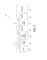
- FIGURE 2 illustrates a system 200 comprising a plurality of components, such as may be employed in a universal production printer with a color print sheet buffer or a tightly-integrated parallel printer (TIPP) system, which represents an environment in which the various features described herein may be employed.
- the system 200 comprises a paper source 202, which may comprise one or more sheets of paper, and which is operatively associated with a color print engine 204 and an inserter 208. Paper from the paper source 202 may follow one of two paths. For instance, paper may be routed from the paper source 202 to the color print engine 204, and on to a color print buffer 206, before entering the inserter 208.
- TIPP tightly-integrated parallel printer
- paper may be routed directly from the paper source 202 to the inserter 208 (e.g., bypassing the color engine 204 and the color print buffer 206 using the highway path 216). Similarly, paper may bypass the black and white engine 210 using the highway path 218.
- Paper that has been routed directly from the paper source 202 to the inserter 208 may be passed to a black-and-white print engine 210, then through a merger 212 that merges black-and-white and color pages, before proceeding on to a finisher 214 that finishes the document for presentation to a user. It will be appreciated that according to other examples, a page may pass through all components of the system 200 and may have both color portions and black-and-white portions.
- the actions associated with a job performed by system 200 may be organized into a series of events that define one or more solutions, or "plans," to the job.
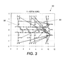
- FIGURE 3 illustrates a network-flow model solution 300 for a media routing job in a machine, such as a TIPP platform or the like.
- the network-flow model relaxes the constraints that materials in a plant (e.g., sheets of paper in the TIPP printer(s)) are discrete and finds the possible routes in the system that maximize the throughput of the plant under the relaxed condition.
- the model is "solved” once and need not take into account the real-time constraints of sheets interleaving at different locations in the printer when the printing job is requested.
- the solution 300 shows a set of potential routes 302 that can achieve a desired throughput for the system.
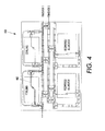
- FIGURE 4 illustrates a model-based online planner solution 400 for a media routing job in a machine, such as a TIPP platform or the like.
- a model-based online planner can build a concrete route for a given printing job, such as the route 402 shown in the figure.
- the route 402 can be built incrementally and takes into account real-time constraints. All possible routes can be examined to ensure the final solution is correct and optimal. For instance, in a printer or the like, starting with an empty route, a given machine capability can be added at each step until a complete route from the input (feeder) to the output (finisher) that goes through necessary modules is completed. If the plan, or route, is built from scratch each time and constraints are not relaxed, the total time to find the solution is difficult to ascertain. However, the solution quality is good if the underlying search algorithm used (e.g. A*) can guarantee optimality.
- the underlying search algorithm used e.g. A*
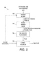
- FIGURE 5 illustrates a planning framework 500 that facilitates quickly locating a precomputed job plan for executing a received job, as well as performing a search for an optimal-quality plan, within a predefined time bound.
- the framework 500 comprises a problem relaxer 502 that receives information associated with a system model, such as a manufacturing plant, assembly line, print platform, etc.
- the problem relaxer 502 can also receive information related to a job to be performed by the modeled system. Once such information is received, the problem relaxer can relax one or more constraints associated with performance of the job (e.g., job duration limits, specific execution criteria, event orderings, etc.) and can output a simplified, or "relaxed," planning problem.
- constraints associated with performance of the job e.g., job duration limits, specific execution criteria, event orderings, etc.
- a relaxed problem solver 504 can receive the simplified planning problem and generate one or more solutions that represent respective plans for executing the received job description.
- the solution(s) can be stored in a precomputed plan database 506 for subsequent access by a planner-scheduler 508.
- the planner-scheduler 508 can receive information relating to a current state of a system, such as a printer, for which a job plan is desired.
- the current state information can describe, without being limited to, a level of resource availability, a level at which system resources are taxed, whether the system is busy executing other jobs, whether and/or when the system will be ready to execute the job currently being planned, etc.
- the planner-scheduler 508 accesses the precomputed plan database 506 and selects a best among plans stored in the database 506 according to the optimization criteria, which may be output as a final plan to the system for execution.
- the planner-scheduler can consider a variety of criteria, including but not limited to compliance with one or more defined constraints, compliance with relaxed constraints, minimum execution time, minimum resource expenditure, and the like.
- the current system state information may be received by the network-flow modeler 502 to provide online system information that permits the network-flow modeler 502 to continuously and/or periodically update a model of the system.
- the planning framework 500 relaxes certain constraints to simplify the planning problem. Depending on the type of relaxation, the planning framework 500 then invokes an appropriate solver 504 to solve the simplified problem, and stores identified solutions in the precomputed plan database 506.
- the planner-scheduler 508 can select a solution from the precomputed plan database 506 and quickly schedule it to ensure that at least one valid plan is available for execution. The planner 508 can then spend the remainder of an allocated planning time trying to find a better (e.g., faster, less expensive, etc.) solution than the initial solution.
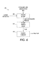
- FIGURE 6 illustrates a planning framework 600 that computes job plans online by employing a greedy search algorithm in conjunction with a constraint relaxing protocol to facilitate finding at least one valid job plan during a first portion of an allocated planning time period while conserving the remaining portion of the planning time period for generation and/or identification of an optimal job plan.
- the framework 600 comprises a problem relaxer 602 that receives system model and/or job description information.
- the problem relaxer 602 may additionally receive information related to a current state of the system, such as jobs to be performed, resource availability, system availability, and the like.
- the problem relaxer 602 can employ the greedy search algorithm to relax and/or ignore one or more constraints on job performance in order to identify a set of events that will suffice to complete the job, which results in an increased number of potential job solutions.
- a simplified job planning problem (e.g., with the reduced constraints) can be output to a solver 604 that can identify one or more plans that satisfy the remaining constraints.
- a best plan returned by the solver 604 may be selected by a planner-scheduler 606 and output as a final plan.
- solver 604 may return an initial job solution that will permit job completing without necessarily complying with one or more constraints.
- a better plan e.g., a plan that conforms to more or all of the original constraints
- FIGURE 7 is an illustration of a planning framework 700 that employs another approach to job planning, wherein job solutions may be selected both from a set of precomputed job plans as well as previously performed job plans that are identified online in real time, which may then be cached along with precomputed plans.
- the framework 700 can comprise a planner-scheduler 702 that receives current state information related to a state of a system for which a job is to be planned.
- the planner-scheduler 702 can additionally retrieve a best plan from a precomputed plan database 704, in which one or more plans for a job request, which have been precomputed during an offline period, may be stored.
- the "precomputed" plan selected by the planner-scheduler 702 is the plan that can complete the requested job with a minimum cost (e.g., of resources, time, etc.), as compared to other plans in the precomputed plan data base.
- the planner-scheduler can generate a final plan, which may comprise modifications to the retrieved precomputed plan, and which may be output for execution.
- the planner may also use the precomputed plan as an upper bound on the final plan quality and try to find a better plan in the remaining allotted planning time. If such a better plan is found, it is output as a final plan.
- the final plan may then be received by a constraint relaxer 706, which may evaluate the plan and, if the plan meets a predefined set of criteria, it may be stored in the precomputed plan database for future evaluation and/or selection by the planner-scheduler 702.
- a constraint relaxer 706 may evaluate the plan and, if the plan meets a predefined set of criteria, it may be stored in the precomputed plan database for future evaluation and/or selection by the planner-scheduler 702.
- a final plan created online by the planner-scheduler 702 may become a precomputed plan for a subsequent call for job planning.
- one or more of the precomputed plans stored in the precomputed plan database 704 may have been created by the planner-scheduler 702 during a previous planning procedure.
- FIGURE 8 illustrates a planning framework 800 that facilitates simplifying a job plan procedure by employing a network-flow model to precompute one or more job plans, and a mixed integer programming (MIP) technique, in accordance with one or more features.
- the planning framework comprises a network flow modeler 802 that receives information associated with a model of a system for which a job is to be planned, as well as information associated with a description of the job to be planned.
- the network-flow modeler 802 may generate a model of the system using MIP encoding techniques, and may simplify the job planning problem to be solved by relaxing discrete relationships between objects to be processed during the job and by ignoring interaction between operations associated with different manufacturing requirements of the job.
- An MIP solver 804 (e.g., which may be a commercial MIP solver, a freeware solver, etc.) can solve the planning problem and provide a potential job solution. Multiple routes and/or plans that are encapsulated in a final solution for the network flow model may then be stored in a precomputed plan database 806. A planner-scheduler 808 can then receive information related to a good precomputed plan and system state information to generate a final plan.
- FIGURE 9 is an illustration of a planning framework 900 that facilitates generating and/or selecting a job plan solution using a connection graph, in accordance with various aspects.
- a connection graph builder 902 can receive information describing a system model and a job to be performed by the system.
- the connection graph builder 902 can generate a connection graph that describes connections between different components of the system used to route objects while ignoring the interactions between different operators associated with moving different objects. For instance, in a printing platform, objects may be pages that require processing or printing, and operators may comprise components that perform actions to process the pages, or the like.
- a shortest path solver 904 receives the connection graph and employs an all-pair shortest path searching algorithm to generate a set solutions, where each solution is representative of a plan for executing the requested job, and such plans may be stored in a precomputed plan database 906.
- a good precomputed plan may then be selected or retrieved by a planner-scheduler 908, which may further optimize the selected plan in accordance with current system state information in order to generate a final plan for execution.
- a final plan may then be output for execution.
- the framework 900 may relax fewer constraints than other frameworks described herein, which may result in improved precomputed plan quality.
- the connection graph may be encoded (but not limited to) using a MIP technique and output a set of MIP encoded solutions.
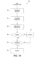
- FIGURE 10 is an illustration of a method 1000 for utilizing precomputed plans to plan a job in a predefined time period, where a sufficient job plan is identified during a first portion of the planning period, and a better job plan is searched for during a second portion of the planning period.
- a set of precomputed plans may be evaluated or otherwise received during the first portion of the planning period, and at 1002, a plan, P1, from among the precomputed plans may be identified as satisfying one or more criteria associated with the job to be performed, and scheduled for execution. For instance, when a manufacturing job is received, a planner may select a plan from a precomputed plan database and schedule it for execution.
- act 1002 can facilitate job planning while taking into account real-time resource constraints and the discreteness of materials being processed during execution of the manufacturing job.
- the manufacturing job may be a printing job in a printer, and the materials may be sheets of paper.
- a new allocation may be scheduled after all other allocations of the same resource to resolve contention; therefore leading to a valid plan without searching.
- the selected or resulting plan P1 may then be used as an upper bound on the quality of a final plan to be searched for or found by the planner during the planning period.
- a maximum planning time, T may be set to delineate a maximum allowable duration of the second portion of the planning period.
- a search may be conducted for a second plan P2, which satisfies the predefined job criteria, and the search may be continued until the expiration of the period T (e.g., the second portion of the planning period).
- a determination may be made regarding whether the second plan P2 has been identified. If not, then at 1014, plan P1 is returned to a planner or other system processor as the best-quality plan identified so far for execution.
- Plan optimity may be determined as a function of one or more parameters associated with plan execution and/or performance.
- parameters affecting optimity of the plan may include, without being limited to, plan execution speed, resource consumption, output quality, etc.
- plan optimity may be a function of print job speed, cost savings associated with one or more resources (e.g., paper, toner, etc.), routing efficiency through the machine, etc.
- P1 is determined to be better than P2
- the method may proceed to 1014, where P1 is output or returned to a processor and/or planner component for execution.
- P2 may be returned as a best-so-far solution for execution of the job or task, at 1012. It will be appreciated that when the cost of plan P1 is used as an upper bound in a branch-and-bound search, the discovery of plan P2 implies that P2 is better than P1. Thus, any further comparison between the costs of P1 and P2 is unnecessary.
- the planning period may be on the order of seconds, milliseconds, microseconds, etc. in duration, and that the first and second portions of the planning period need not be of equal length.
- the planning period may be in the range of approximately 100ms to approximately 2 seconds, and the first and second portions thereof may exhibit approximately a 1:2 ratio in length.
- the first portion thereof e.g., corresponding to act 102
- the remaining approximately 190ms may be allocated for the second portion of the planning period (e.g., corresponding to acts 1004-1014).
- the method is iterated multiple times within the planning time period to evaluate more than two plans and select a best plan for execution. It is to be understood that the foregoing examples are illustrative in nature and are not intended to limit the duration of the planning period, respective portions thereof, or the ratio of the duration of the first planning period portion to the second planning period portion.
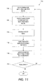
- FIGURE 11 illustrates a method 1100 for evaluating a print job that is to be performed by a print platform, selecting a first job plan that at least meets minimum criteria for performing the job to ensure that at least one plan is available, and identifying an optimal plan for performing the job to improve job execution and performance, in accordance with various aspects.
- the method 1100 may be performed by a planning component, such as the planner described with regard to the preceding figures.
- the job plan may comprise determining one or more routes (e.g., through the printer) along which one or more pages may travel to be processed to ensure that the text on the page is properly printed, similarly for other automated manufacturing domains.
- a machine model is evaluated, a network-flow model there for is generated and solved, and the possible routes encapsulated in the final solution of the network-flow model are stored.
- Act 1102 can be performed rapidly because the network-flow model relaxes discreteness and real-time constraints associated with job execution.
- an incoming print job is detected and analyzed by a planner, which selects one of the routes precomputed by the network-flow model and tries to schedule it, at 1106. The selected plan is used as an upper-bound on the final plan to be found by the planner.
- a search is conducted at 1108, for a limited amount of time, for a better solution than the initial solution selected at 1104 from the network-flow solutions.
- the planner can output the initial plan selected from the network-flow solution, at 1110. If there is a better solution, then the plan associated with the better solution may be output at 1110. At 1112, a determination may be made as to whether the network-flow model has changed. Whenever there is a model change, such as a module in the model going off/on-line, then the method reverts to 1102 and a new network-flow model is built, solved again, and the new potential routes are stored in the database.
- a model change such as a module in the model going off/on-line
- Network-flow as described above (e.g. used as a solver in 1102) is one of several manners in which a set of relaxed solutions may be searched to quickly return one solution for online planning.
- the network-flow model need not take into account the discreteness of the materials and the online aspect of the system (e.g., ignoring the potential interaction with other pieces of materials moving in the plant).
- Another variation of this approach can comprise taking limited "online” information into account and set up a network-flow model at each stage when a new job comes in, as well as approximating the discreteness of the materials when solving the network-flow model.
- the network-flow model is used in conjunction with various aspects described herein, other approaches such as "relaxed-plan" in academic planning research can be used as additional or alternative ways to precompute a set of candidate plans.
- the "relaxed-plan” approach works by relaxing logical interactions between actions/capability, but not the constraints on the discreteness of the materials as in the network-flow model.
- a larger or smaller set of constraints can be relaxed when employing the presented network-flow model discussed above.
- Another approach is to use the all-pair shortest path algorithms to catch all possible routes upfront. This approach relaxes the interactions between different objects/sheets but take into account the discreteness of the objects.
Landscapes
- Engineering & Computer Science (AREA)
- Business, Economics & Management (AREA)
- Economics (AREA)
- Human Resources & Organizations (AREA)
- Strategic Management (AREA)
- Tourism & Hospitality (AREA)
- Theoretical Computer Science (AREA)
- General Physics & Mathematics (AREA)
- Entrepreneurship & Innovation (AREA)
- Marketing (AREA)
- General Business, Economics & Management (AREA)
- Physics & Mathematics (AREA)
- Game Theory and Decision Science (AREA)
- Quality & Reliability (AREA)
- Operations Research (AREA)
- Development Economics (AREA)
- Educational Administration (AREA)
- Manufacturing & Machinery (AREA)
- Health & Medical Sciences (AREA)
- General Health & Medical Sciences (AREA)
- Primary Health Care (AREA)
- Management, Administration, Business Operations System, And Electronic Commerce (AREA)
- General Factory Administration (AREA)
- Powder Metallurgy (AREA)
- Control Of Heat Treatment Processes (AREA)
Abstract
Description
- Various features described herein relate generally to a tightly-integrated parallel printing architecture and more specifically to print job plan optimization.
- As printing machines and related components become more complex, a need arises for systems and methods that facilitate processing numerous commands and ever-more-copious amounts of information. On the other hand, as processor speed increases and memory capacity grows, print platforms become increasingly complex in order to fully exploit the processing power of modern computing systems. The trends of increasing processing power to meet system demands and then increasing system functionality to maximize utilization of available processing power combine to cause a marked increase in the complexity of printing systems.
- Conventional planning algorithms attempt to generate a planned ordering or sequence of events for processing a print job received at a printer. When multiple printing options are involved in a print job, careful routing of a sequence of pages to be printed through a printer can become crucial. For instance, print job planning can facilitate conserving resources such as toner and paper while improving throughput of a printing platform.
- In model-based planning, especially for online planning for manufacturing systems such as printers, the speed of the planner is critical. A conventional online planner constructs plans from scratch incrementally when a new job request is received. This allows for the exploration of all possibilities and finds good quality and even optimal plans. However, this approach can lead to a lengthy planning time when the system is complex. Accordingly, a need exists for systems and/or methods that facilitate quickly locating a job plan for executing a received job, as well as performing additional search for an optimal-quality plan, within predefined time bound.
- A method of planning a job in a machine environment comprises receiving a job to be planned, analyzing a set of precomputed plans to identify a first plan that is feasible, and scheduling the first plan as a default plan. The method further comprises setting a maximum planning time period to identify a second plan, identifying the second plan if available, and determining whether the second plan is better than the first plan.
- A system for performing offline and online job planning for a machine job comprises a constraint library that stores at least one constraint that is employed to ensure that a given job plan conforms to a job request, and a planner that analyzes a precomputed plan database and identifies a first plan to satisfy the job request during a first portion of a predefined planning period, and attempts to identify a second plan during a second portion of the predefined planning period. The system further comprises an optimizer that compares the first plan and the second plan to determine which plan is better for executing the job request.
In a further embodiment of the system of claim 9, iterated at least once to evaluate at least a third plan within the given length of time.
In a further embodiment the planner schedules the better of the first and second plans upon an indication thereof from the optimizer.
In a further embodiment the system further comprises a constraint relaxer that relaxes one or more constraints to increase a number of plans identified as satisfying the job request.
In a further embodiment the system further comprises a constraint relaxer that removes one or more constraints to facilitate finding a plan using a smaller set of constraints.
In a further embodiment the predefined planning period is less than approximately 1 second in duration.
In a further embodiment the predefined planning period is approximately 0.2 seconds to approximately 0.5 seconds in duration.
In a further embodiment the first portion of the predefined planning period is approximately one-third of the total predefined planning period, and wherein the second portion of the predefined planning period is the other approximately two-thirds of the predefined planning period.
In a further embodiment the job is a print job and the machine comprises a print platform.
In a further embodiment the at least one constraint relates to a maximum allowable job execution time period.
In a further embodiment the at least one constraint relates to a maximum allowable number of components employed to execute the job.
In a further embodiment the at least one constraint relates to interferences between different operators in the system.
In a further embodiment the at least one constraint relates to interferences between different objects moving in the system.
In one embodiment of the system ofclaim 10, the components are xerographic components for performing a xerographic process.
In a further embodiment the xerographic components are part of a tightly-integrated parallel printing platform. -
FIGURE 1 illustrates a system that comprises a planner that is operatively coupled to a machine, and which may plan jobs for the machine; -
FIGURE 2 illustrates a system comprising a plurality of components, such as may be employed in a universal production printer with a color print sheet buffer or a tightly-integrated parallel printer (TIPP) system, which represents an environment in which the various features described herein may be employed. -
FIGURE 3 illustrates a network-flow model solution for a media routing job in a machine, such as a TIPP platform or the like. -
FIGURE 4 illustrates a model-based online planner solution for a media routing job in a machine, such as a TIPP platform or the like. -
FIGURE 5 illustrates a planning framework that facilitates quickly locating a job plan for executing a received job, as well as performing a search for an optimal-quality plan, within predefined time bound. -
FIGURE 6 illustrates a planning framework that employs a greedy search algorithm in conjunction with a constraint relaxing protocol to facilitate finding at least one valid job plan during a first portion of an allocated planning time period while conserving the remaining portion of the planning time period for generation and/or identification of an optimal job plan. -
FIGURE 7 is an illustration of a planning framework that employs another approach to job planning, wherein job solutions may be selected both from a set of precomputed job plans as well as previously performed job plans that are identified online in real time. -
FIGURE 8 illustrates a planning framework that facilitates simplifying a job plan procedure by employing an integer linear programming (ILP) technique, in accordance with one or more features. -
FIGURE 9 is an illustration of a planning framework that facilitates generating and/or selecting a job plan solution using a connection graph, in accordance with various aspects. -
FIGURE 10 is an illustration of a method for utilizing precomputed plans to plan a job in a predefined time period, where a sufficient job plan is identified during a first portion of the planning period, and a better job plan is searched for during a second portion of the planning period. -
FIGURE 11 illustrates a method for evaluating a print job that is to be performed by a print platform, selecting a first job plan that at least meets minimum criteria for performing the job to ensure that at least one plan is available, and then identifying a better plan for performing the job to improve job execution and performance, in accordance with various aspects such as bound on total time to search for a plan. - Various features described herein relate to an approach for reducing planning time by intelligently using a set of precomputed plans to quickly select a solution to a given job. A planner may then use the rest of the allotted planning time to improve on the initially selected solution. An advantage of this approach compared to the current practice is the ability to find a valid plan very quickly. Thus, in systems that demand fast planning, such as multiple-IME printers, the approach can provide performance guarantee in scenarios where real-time constraints make it difficult for a conventional planner to find an optimal plan that can achieve the maximum productivity of the system in a reasonable time frame.
- With reference to
FIGURE 1 , asystem 100 comprises aplanner 102 that is operatively coupled to amachine 104, and which may plan jobs for themachine 104. For example, the machine may be a router in a manufacturing environment and may route objects from one manufacturing device to another. In such a scenario, theplanner 102 may determine an optimal plan or schedule for movement of an object to and from various devices within the manufacturing environment. According to another example, themachine 104 may be a printer, and theplanner 102 may facilitate optimizing execution of a print job or the like by finding an optimal way to route sheets of paper from one component to another. - The
planner 102 comprises aconstraint library 106 that stores information related to one or more constraints that may be applied when constructing and/or selecting a plan for a received task or job. For example, a temporal constraint may be associated with a job solution, such as a predetermined maximum time period in which the job is to be completed, or a predetermined maximum time period for identifying or selecting a job solution, etc. As another example, a constraint may relate to ensuring that an optimal solution is selected, such as a constraint that indicates a preference for a job solution that utilizes a smallest number of components to complete the job. In another example the constraint library comprises constraints related to the discreteness of objects to be scheduled and/or interactions between different activities of different objects. In still other examples, the library comprises constraints that relate to interferences between different operators in the system, and/or to interferences between different objects moving in the system. Theconstraint library 106 may comprise constraints such as the foregoing and any other suitable or desirable constraints, such as will be appreciated by those of skill. - The
planner 102 further comprises aconstraint relaxer 108 that selectively relaxes and/or removes one or more constraints applied when generating and/or selecting a job solution, or plan, in order to make it easier to find a plan quickly by increasing the number of plans that may be generated or identified for a given job. For instance, by relaxing one or more constraints on a job plan criterion, constraintrelaxer 108 can increase a number of job plans that are identified as acceptable for job execution, thereby increasing a number of options available. As a consequence, make it easier to find a satisfying or optimal plan (subject to the relaxed set of constraints). As an example, a temporal constraint may dictate that a preferred job plan has an execution time not greater than 10 seconds, and an ordering constraint may dictate that events a, b, and c are performed in consecutive order. In a case where six possible job solutions can be executed in 10 seconds or fewer, but only one solution performs events a, b, and c in the desired order, then constraintrelaxer 108 may relax the ordering constraint to permit, for instance, events b and c to occur in any order so long as event a occurs first, which may result in a higher number of satisfactory job solutions. As a related example,constraint relaxer 108 may completely remove the ordering constraint to make all six job plans available for selection and/or execution. - A
plan database 110 can store one or more job plans, or solutions, which may be pre-computed or may be generated upon receiving a job or task. Theplan database 110 can store information related to one or more selected plans, identified as meeting all criteria and/or constraints associated with a given job, and/or any other information related to job planning and/or execution. Additionally, theplanner 102 comprises anoptimizer 112 that identifies an optimal plan in a set of one or more plans that meet given constraints. According to an example wherein themachine 104 is a printer or other xerographic machine, theoptimizer 112 can determine that a plan with a shortest execution time is desirable over plans that take longer to perform, while conservation of a particular resource, such as paper or toner, is less important given a particular set of conditions (e.g., a job queue is full or almost full, etc.). In such a case, theoptimizer 112 may instruct theconstraint relaxer 108 to relax or remove a constraint that requires a minimal usage of toner, which in turn may permit job plans with shortest execution time to be identified, analyzed, selected, etc., in less time. - According to other examples, when a model of the
machine 104 or, for instance, a manufacturing plant is provided to theplanner 102, theplanner 102 can use the model to compute possible "routes" (e.g., of an object through the manufacturing plant, a machine, a printer, etc.), or job plans, that optimize the overall throughput of the plant or themachine 104. While doing so, theplanner 102, via theconstraint relaxer 108, can relax certain constraints to reduce job solution selection time. For instance, theplanner 102 can use a network flow-based optimizer. Theplanner 102 can then store the job plans, computed under the relaxed condition, in theplan database 110, and can try to use them first when searching for a plan for a new job. A satisfactory plan can thus be found quickly because a need for a planning search or scheduling search is mitigated. The satisfactory plan can then be used as an upper bound for subsequent planning searches for better plans in the allowed planning time. Thus,system 100 provides a flexible framework that can be used with branch-and-bound, best-first, or any "anytime" search algorithm employed by theplanner 102. -
FIGURE 2 illustrates asystem 200 comprising a plurality of components, such as may be employed in a universal production printer with a color print sheet buffer or a tightly-integrated parallel printer (TIPP) system, which represents an environment in which the various features described herein may be employed. Thesystem 200 comprises apaper source 202, which may comprise one or more sheets of paper, and which is operatively associated with acolor print engine 204 and aninserter 208. Paper from thepaper source 202 may follow one of two paths. For instance, paper may be routed from thepaper source 202 to thecolor print engine 204, and on to acolor print buffer 206, before entering theinserter 208. Additionally or alternatively, paper may be routed directly from thepaper source 202 to the inserter 208 (e.g., bypassing thecolor engine 204 and thecolor print buffer 206 using the highway path 216). Similarly, paper may bypass the black andwhite engine 210 using thehighway path 218. - Paper that has been routed directly from the
paper source 202 to theinserter 208 may be passed to a black-and-white print engine 210, then through amerger 212 that merges black-and-white and color pages, before proceeding on to afinisher 214 that finishes the document for presentation to a user. It will be appreciated that according to other examples, a page may pass through all components of thesystem 200 and may have both color portions and black-and-white portions. The actions associated with a job performed bysystem 200 may be organized into a series of events that define one or more solutions, or "plans," to the job. -
FIGURE 3 illustrates a network-flow model solution 300 for a media routing job in a machine, such as a TIPP platform or the like. Given a model, the network-flow model relaxes the constraints that materials in a plant (e.g., sheets of paper in the TIPP printer(s)) are discrete and finds the possible routes in the system that maximize the throughput of the plant under the relaxed condition. The model is "solved" once and need not take into account the real-time constraints of sheets interleaving at different locations in the printer when the printing job is requested. The solution 300 shows a set ofpotential routes 302 that can achieve a desired throughput for the system. -
FIGURE 4 illustrates a model-basedonline planner solution 400 for a media routing job in a machine, such as a TIPP platform or the like. A model-based online planner can build a concrete route for a given printing job, such as theroute 402 shown in the figure. Theroute 402 can be built incrementally and takes into account real-time constraints. All possible routes can be examined to ensure the final solution is correct and optimal. For instance, in a printer or the like, starting with an empty route, a given machine capability can be added at each step until a complete route from the input (feeder) to the output (finisher) that goes through necessary modules is completed. If the plan, or route, is built from scratch each time and constraints are not relaxed, the total time to find the solution is difficult to ascertain. However, the solution quality is good if the underlying search algorithm used (e.g. A*) can guarantee optimality. -
FIGURE 5 illustrates aplanning framework 500 that facilitates quickly locating a precomputed job plan for executing a received job, as well as performing a search for an optimal-quality plan, within a predefined time bound. Theframework 500 comprises aproblem relaxer 502 that receives information associated with a system model, such as a manufacturing plant, assembly line, print platform, etc. Theproblem relaxer 502 can also receive information related to a job to be performed by the modeled system. Once such information is received, the problem relaxer can relax one or more constraints associated with performance of the job (e.g., job duration limits, specific execution criteria, event orderings, etc.) and can output a simplified, or "relaxed," planning problem. Arelaxed problem solver 504 can receive the simplified planning problem and generate one or more solutions that represent respective plans for executing the received job description. The solution(s) can be stored in aprecomputed plan database 506 for subsequent access by a planner-scheduler 508. - According to an example, the planner-
scheduler 508 can receive information relating to a current state of a system, such as a printer, for which a job plan is desired. The current state information can describe, without being limited to, a level of resource availability, a level at which system resources are taxed, whether the system is busy executing other jobs, whether and/or when the system will be ready to execute the job currently being planned, etc. The planner-scheduler 508 accesses theprecomputed plan database 506 and selects a best among plans stored in thedatabase 506 according to the optimization criteria, which may be output as a final plan to the system for execution. In determining whether a given plan is the best plan, the planner-scheduler can consider a variety of criteria, including but not limited to compliance with one or more defined constraints, compliance with relaxed constraints, minimum execution time, minimum resource expenditure, and the like. According to a related example, the current system state information may be received by the network-flow modeler 502 to provide online system information that permits the network-flow modeler 502 to continuously and/or periodically update a model of the system. - In this manner, when a machine model and/or a job description is received, the
planning framework 500 relaxes certain constraints to simplify the planning problem. Depending on the type of relaxation, theplanning framework 500 then invokes anappropriate solver 504 to solve the simplified problem, and stores identified solutions in theprecomputed plan database 506. In real time, when a job request is received, the planner-scheduler 508 can select a solution from theprecomputed plan database 506 and quickly schedule it to ensure that at least one valid plan is available for execution. Theplanner 508 can then spend the remainder of an allocated planning time trying to find a better (e.g., faster, less expensive, etc.) solution than the initial solution. -
FIGURE 6 illustrates aplanning framework 600 that computes job plans online by employing a greedy search algorithm in conjunction with a constraint relaxing protocol to facilitate finding at least one valid job plan during a first portion of an allocated planning time period while conserving the remaining portion of the planning time period for generation and/or identification of an optimal job plan. Theframework 600 comprises aproblem relaxer 602 that receives system model and/or job description information. Theproblem relaxer 602 may additionally receive information related to a current state of the system, such as jobs to be performed, resource availability, system availability, and the like. Based on the received information, theproblem relaxer 602 can employ the greedy search algorithm to relax and/or ignore one or more constraints on job performance in order to identify a set of events that will suffice to complete the job, which results in an increased number of potential job solutions. A simplified job planning problem (e.g., with the reduced constraints) can be output to asolver 604 that can identify one or more plans that satisfy the remaining constraints. A best plan returned by thesolver 604 may be selected by a planner-scheduler 606 and output as a final plan. Thus,solver 604 may return an initial job solution that will permit job completing without necessarily complying with one or more constraints. Given that thatrelaxed problem solver 604 ignore some constraints to make the problem easier to solve, its solution may not be optimal according to all of the original constraints. A better plan (e.g., a plan that conforms to more or all of the original constraints) may be searched for and/or generated during a later portion of a predefined planning period. -
FIGURE 7 is an illustration of aplanning framework 700 that employs another approach to job planning, wherein job solutions may be selected both from a set of precomputed job plans as well as previously performed job plans that are identified online in real time, which may then be cached along with precomputed plans. For instance, theframework 700 can comprise a planner-scheduler 702 that receives current state information related to a state of a system for which a job is to be planned. The planner-scheduler 702 can additionally retrieve a best plan from aprecomputed plan database 704, in which one or more plans for a job request, which have been precomputed during an offline period, may be stored. The "precomputed" plan selected by the planner-scheduler 702 is the plan that can complete the requested job with a minimum cost (e.g., of resources, time, etc.), as compared to other plans in the precomputed plan data base. Once the precomputed plan has been selected, the planner-scheduler can generate a final plan, which may comprise modifications to the retrieved precomputed plan, and which may be output for execution. The planner may also use the precomputed plan as an upper bound on the final plan quality and try to find a better plan in the remaining allotted planning time. If such a better plan is found, it is output as a final plan. The final plan may then be received by aconstraint relaxer 706, which may evaluate the plan and, if the plan meets a predefined set of criteria, it may be stored in the precomputed plan database for future evaluation and/or selection by the planner-scheduler 702. In this manner, a final plan created online by the planner-scheduler 702 may become a precomputed plan for a subsequent call for job planning. Similarly, one or more of the precomputed plans stored in theprecomputed plan database 704 may have been created by the planner-scheduler 702 during a previous planning procedure. -
FIGURE 8 illustrates aplanning framework 800 that facilitates simplifying a job plan procedure by employing a network-flow model to precompute one or more job plans, and a mixed integer programming (MIP) technique, in accordance with one or more features. The planning framework comprises anetwork flow modeler 802 that receives information associated with a model of a system for which a job is to be planned, as well as information associated with a description of the job to be planned. The network-flow modeler 802 may generate a model of the system using MIP encoding techniques, and may simplify the job planning problem to be solved by relaxing discrete relationships between objects to be processed during the job and by ignoring interaction between operations associated with different manufacturing requirements of the job. An MIP solver 804 (e.g., which may be a commercial MIP solver, a freeware solver, etc.) can solve the planning problem and provide a potential job solution. Multiple routes and/or plans that are encapsulated in a final solution for the network flow model may then be stored in aprecomputed plan database 806. A planner-scheduler 808 can then receive information related to a good precomputed plan and system state information to generate a final plan. -
FIGURE 9 is an illustration of aplanning framework 900 that facilitates generating and/or selecting a job plan solution using a connection graph, in accordance with various aspects. Aconnection graph builder 902 can receive information describing a system model and a job to be performed by the system. Theconnection graph builder 902 can generate a connection graph that describes connections between different components of the system used to route objects while ignoring the interactions between different operators associated with moving different objects. For instance, in a printing platform, objects may be pages that require processing or printing, and operators may comprise components that perform actions to process the pages, or the like. A shortest path solver 904 receives the connection graph and employs an all-pair shortest path searching algorithm to generate a set solutions, where each solution is representative of a plan for executing the requested job, and such plans may be stored in aprecomputed plan database 906. A good precomputed plan may then be selected or retrieved by a planner-scheduler 908, which may further optimize the selected plan in accordance with current system state information in order to generate a final plan for execution. A final plan may then be output for execution. By ignoring only interactions between operators in the system model and accounting for object discreteness, theframework 900 may relax fewer constraints than other frameworks described herein, which may result in improved precomputed plan quality. The connection graph may be encoded (but not limited to) using a MIP technique and output a set of MIP encoded solutions. -
FIGURE 10 is an illustration of amethod 1000 for utilizing precomputed plans to plan a job in a predefined time period, where a sufficient job plan is identified during a first portion of the planning period, and a better job plan is searched for during a second portion of the planning period. A set of precomputed plans may be evaluated or otherwise received during the first portion of the planning period, and at 1002, a plan, P1, from among the precomputed plans may be identified as satisfying one or more criteria associated with the job to be performed, and scheduled for execution. For instance, when a manufacturing job is received, a planner may select a plan from a precomputed plan database and schedule it for execution. Thus,act 1002 can facilitate job planning while taking into account real-time resource constraints and the discreteness of materials being processed during execution of the manufacturing job. According to an example, the manufacturing job may be a printing job in a printer, and the materials may be sheets of paper. When scheduling an allocation of a resource, a new allocation may be scheduled after all other allocations of the same resource to resolve contention; therefore leading to a valid plan without searching. The selected or resulting plan P1 may then be used as an upper bound on the quality of a final plan to be searched for or found by the planner during the planning period. - At 1004, a maximum planning time, T, may be set to delineate a maximum allowable duration of the second portion of the planning period. At 1006, a search may be conducted for a second plan P2, which satisfies the predefined job criteria, and the search may be continued until the expiration of the period T (e.g., the second portion of the planning period). At 1008, a determination may be made regarding whether the second plan P2 has been identified. If not, then at 1014, plan P1 is returned to a planner or other system processor as the best-quality plan identified so far for execution.
- If a second satisfactory plan is identified at 1008, then a determination may be made regarding whether plan P2 is better than plan P1, at 1010. Plan optimity may be determined as a function of one or more parameters associated with plan execution and/or performance. For example, parameters affecting optimity of the plan may include, without being limited to, plan execution speed, resource consumption, output quality, etc. In a specific example relating to a printer or xerographic machine, plan optimity may be a function of print job speed, cost savings associated with one or more resources (e.g., paper, toner, etc.), routing efficiency through the machine, etc. If P1 is determined to be better than P2, then the method may proceed to 1014, where P1 is output or returned to a processor and/or planner component for execution. If it is determined that P2 is better than P1, then P2 may be returned as a best-so-far solution for execution of the job or task, at 1012. It will be appreciated that when the cost of plan P1 is used as an upper bound in a branch-and-bound search, the discovery of plan P2 implies that P2 is better than P1. Thus, any further comparison between the costs of P1 and P2 is unnecessary.
- It will be appreciated that the planning period may be on the order of seconds, milliseconds, microseconds, etc. in duration, and that the first and second portions of the planning period need not be of equal length. For example, the planning period may be in the range of approximately 100ms to approximately 2 seconds, and the first and second portions thereof may exhibit approximately a 1:2 ratio in length. According to another example, if the total duration of the planning period is 300ms, then the first portion thereof (e.g., corresponding to act 102) may have a duration of approximately 110ms, and the remaining approximately 190ms may be allocated for the second portion of the planning period (e.g., corresponding to acts 1004-1014). According to yet another example, the method is iterated multiple times within the planning time period to evaluate more than two plans and select a best plan for execution. It is to be understood that the foregoing examples are illustrative in nature and are not intended to limit the duration of the planning period, respective portions thereof, or the ratio of the duration of the first planning period portion to the second planning period portion.
-
FIGURE 11 illustrates amethod 1100 for evaluating a print job that is to be performed by a print platform, selecting a first job plan that at least meets minimum criteria for performing the job to ensure that at least one plan is available, and identifying an optimal plan for performing the job to improve job execution and performance, in accordance with various aspects. Themethod 1100 may be performed by a planning component, such as the planner described with regard to the preceding figures. In the case of a print platform or other xerographic or imaging machine, the job plan may comprise determining one or more routes (e.g., through the printer) along which one or more pages may travel to be processed to ensure that the text on the page is properly printed, similarly for other automated manufacturing domains. At 1102, a machine model is evaluated, a network-flow model there for is generated and solved, and the possible routes encapsulated in the final solution of the network-flow model are stored.Act 1102 can be performed rapidly because the network-flow model relaxes discreteness and real-time constraints associated with job execution. At 1104, an incoming print job is detected and analyzed by a planner, which selects one of the routes precomputed by the network-flow model and tries to schedule it, at 1106. The selected plan is used as an upper-bound on the final plan to be found by the planner. A search is conducted at 1108, for a limited amount of time, for a better solution than the initial solution selected at 1104 from the network-flow solutions. If there is no better solution, the planner can output the initial plan selected from the network-flow solution, at 1110. If there is a better solution, then the plan associated with the better solution may be output at 1110. At 1112, a determination may be made as to whether the network-flow model has changed. Whenever there is a model change, such as a module in the model going off/on-line, then the method reverts to 1102 and a new network-flow model is built, solved again, and the new potential routes are stored in the database. - It will be noted that the final solution can go through the scheduling process at 1104 that takes into account the real-time resource constraints and the discreteness of the materials (e.g. sheets), even if it is not a valid plan when selected from the precomputed routes by the network-flow. "Network-flow" as described above (e.g. used as a solver in 1102) is one of several manners in which a set of relaxed solutions may be searched to quickly return one solution for online planning. The network-flow model need not take into account the discreteness of the materials and the online aspect of the system (e.g., ignoring the potential interaction with other pieces of materials moving in the plant). Another variation of this approach can comprise taking limited "online" information into account and set up a network-flow model at each stage when a new job comes in, as well as approximating the discreteness of the materials when solving the network-flow model. While the network-flow model is used in conjunction with various aspects described herein, other approaches such as "relaxed-plan" in academic planning research can be used as additional or alternative ways to precompute a set of candidate plans. For instance, the "relaxed-plan" approach works by relaxing logical interactions between actions/capability, but not the constraints on the discreteness of the materials as in the network-flow model. Moreover, a larger or smaller set of constraints can be relaxed when employing the presented network-flow model discussed above. Another approach is to use the all-pair shortest path algorithms to catch all possible routes upfront. This approach relaxes the interactions between different objects/sheets but take into account the discreteness of the objects.
Claims (10)
- A method of planning a job in a machine environment, comprising:receiving a job to be planned;analyzing a set of precomputed plans to identify a first plan that is feasible;scheduling the first plan as a default plan;setting a maximum planning time period to identify a second plan;identifying the second plan if available; anddetermining whether the second plan is better than the first plan.
- The method of claim 1, further comprising executing the first plan if the second plan is not available or if the second plan is not better than the first plan.
The method of claim 1, further comprising scheduling and executing the second plan if the second plan is better than the first plan. - The method of claim 1, further comprising determining the quality of the first plan and the second plan as a function of job execution time, wherein smaller execution time correlates to better quality.
- The method of claim 4, iterated at least once to evaluate more than two plans within the given length of time.
- The method of claim 1, further comprising determining the quality of the first plan and the second plan as a function of a number of components involved in the execution of the job, wherein fewer components correlates to better quality.
- The method of claim 1, further comprising receiving system model information, relaxing at least one constraint associated with the system model, and solving the relaxed system model to generate one or more precomputed plans.
- The method of claim 7, wherein the at least one constraint is related to at least one of a predetermined maximum job execution time, a predetermined maximum number of components employed to complete the job, a discreteness of objects to be scheduled, the interactions between different activities of different objects, or an ordering of events occur during job execution.
- A system for performing offline and online job planning for a machine job, comprising:a constraint library that stores at least one constraint that is employed to ensure that a given job plan conforms to a job request;a planner that analyzes a precomputed plan database and identifies a first plan to satisfy the job request during a first portion of a predefined planning period, and attempts to identify a second plan during a second portion of the predefined planning period; andan optimizer that compares the first plan and the second plan to determine which plan is better for executing the job request.
- The system of claim 9, wherein the planner schedules the first plan if the second plan is not identified.
- A system comprising:one or more components that execute instructions for performing a process;a planner that receives a job request, analyzes a set of precomputed job plans to identify a first plan that satisfies one or more job performance-related constraints during a first portion of a planning period, and identifies at least a second plan that satisfies the one or more job performance-related constraints during a second portion of the planning period;an optimizer that compares the first and the at least second plan, if such is found, to determine which plan is better;wherein the planner schedules the first plan for execution upon identifying the first plan, and schedules the at least second plan in place of the first plan if the at least second plan is determined to be better than the first plan.
Applications Claiming Priority (1)
| Application Number | Priority Date | Filing Date | Title |
|---|---|---|---|
| US11/807,475 US7925366B2 (en) | 2007-05-29 | 2007-05-29 | System and method for real-time system control using precomputed plans |
Publications (2)
| Publication Number | Publication Date |
|---|---|
| EP2000899A2 true EP2000899A2 (en) | 2008-12-10 |
| EP2000899A3 EP2000899A3 (en) | 2008-12-31 |
Family
ID=39930447
Family Applications (1)
| Application Number | Title | Priority Date | Filing Date |
|---|---|---|---|
| EP08157086A Withdrawn EP2000899A3 (en) | 2007-05-29 | 2008-05-28 | System and method for real-time system control using precomputed plans |
Country Status (3)
| Country | Link |
|---|---|
| US (1) | US7925366B2 (en) |
| EP (1) | EP2000899A3 (en) |
| JP (2) | JP2008299846A (en) |
Families Citing this family (11)
| Publication number | Priority date | Publication date | Assignee | Title |
|---|---|---|---|---|
| US8464268B2 (en) * | 2009-09-14 | 2013-06-11 | Palo Alto Research Center Incorporated | Dynamic scheduling of jobs/batches using earliest completion time algorithm in cellular manufacturing with batch-splitting of jobs above certain size |
| US8769542B2 (en) | 2010-10-26 | 2014-07-01 | Palo Alto Research Center Incorporated | System for adaptive lot sizing in cellular manufacturing for balancing workloads across multiple cells using split-then-merge operations and earliest completion route algorithm |
| CN103065197A (en) * | 2012-12-12 | 2013-04-24 | 中国能源建设集团广东省电力设计研究院 | Optimal configuration method of distributed combined cooling heating and power system |
| US10783144B2 (en) | 2016-04-01 | 2020-09-22 | Arista Networks, Inc. | Use of null rows to indicate the end of a one-shot query in network switch |
| US10817512B2 (en) | 2016-04-01 | 2020-10-27 | Arista Networks, Inc. | Standing queries in memory |
| US10284673B2 (en) * | 2016-04-01 | 2019-05-07 | Arista Networks, Inc. | Interface for a client of a network device |
| US10860568B2 (en) | 2016-04-01 | 2020-12-08 | Arista Networks, Inc. | External data source linking to queries in memory |
| US10783147B2 (en) | 2016-04-01 | 2020-09-22 | Arista Networks, Inc. | Query result flow control in a network switch |
| US10642844B2 (en) | 2016-04-01 | 2020-05-05 | Arista Networks, Inc. | Non-materialized tables with standing queries |
| US11727289B2 (en) * | 2018-05-04 | 2023-08-15 | International Business Machines Corporation | Iterative generation of top quality plans in automated plan generation for artificial intelligence applications and the like |
| JP2022019070A (en) * | 2020-07-17 | 2022-01-27 | 富士フイルムビジネスイノベーション株式会社 | Production planning equipment, program |
Family Cites Families (121)
| Publication number | Priority date | Publication date | Assignee | Title |
|---|---|---|---|---|
| US4579446A (en) | 1982-07-12 | 1986-04-01 | Canon Kabushiki Kaisha | Both-side recording system |
| US4587532A (en) | 1983-05-02 | 1986-05-06 | Canon Kabushiki Kaisha | Recording apparatus producing multiple copies simultaneously |
| JP2590477B2 (en) | 1987-05-13 | 1997-03-12 | 富士ゼロックス株式会社 | Paper transport direction change device |
| DE3852234T2 (en) | 1987-08-12 | 1995-05-04 | Canon Kk | Sheet conveying apparatus and sheet conveying method. |
| US4836119A (en) | 1988-03-21 | 1989-06-06 | The Charles Stark Draper Laboratory, Inc. | Sperical ball positioning apparatus for seamed limp material article assembly system |
| JP2636441B2 (en) | 1989-11-09 | 1997-07-30 | 富士ゼロックス株式会社 | Image recording device |
| US5095342A (en) | 1990-09-28 | 1992-03-10 | Xerox Corporation | Methods for sheet scheduling in an imaging system having an endless duplex paper path loop |
| US5080340A (en) | 1991-01-02 | 1992-01-14 | Eastman Kodak Company | Modular finisher for a reproduction apparatus |
| US5159395A (en) | 1991-08-29 | 1992-10-27 | Xerox Corporation | Method of scheduling copy sheets in a dual mode duplex printing system |
| US5272511A (en) | 1992-04-30 | 1993-12-21 | Xerox Corporation | Sheet inserter and methods of inserting sheets into a continuous stream of sheets |
| JPH05324665A (en) * | 1992-05-15 | 1993-12-07 | Kobe Steel Ltd | Processing order plan generating method |
| JP3327357B2 (en) * | 1993-03-19 | 2002-09-24 | 富士ゼロックス株式会社 | Printer management method |
| US5358238A (en) | 1993-04-27 | 1994-10-25 | Xerox Corporation | Shared user printer output dynamic "mailbox" system |
| US5326093A (en) | 1993-05-24 | 1994-07-05 | Xerox Corporation | Universal interface module interconnecting various copiers and printers with various sheet output processors |
| US5473419A (en) | 1993-11-08 | 1995-12-05 | Eastman Kodak Company | Image forming apparatus having a duplex path with an inverter |
| US5596416A (en) | 1994-01-13 | 1997-01-21 | T/R Systems | Multiple printer module electrophotographic printing device |
| US5525031A (en) | 1994-02-18 | 1996-06-11 | Xerox Corporation | Automated print jobs distribution system for shared user centralized printer |
| US5778377A (en) | 1994-11-04 | 1998-07-07 | International Business Machines Corporation | Table driven graphical user interface |
| US5596389A (en) * | 1994-12-12 | 1997-01-21 | Xerox Corporation | Apparatus and method for scheduling an imagable substrate and a special sheet to be fed in the same pitch |
| US5570172A (en) | 1995-01-18 | 1996-10-29 | Xerox Corporation | Two up high speed printing system |
| US5557367A (en) | 1995-03-27 | 1996-09-17 | Xerox Corporation | Method and apparatus for optimizing scheduling in imaging devices |
| US5489969A (en) | 1995-03-27 | 1996-02-06 | Xerox Corporation | Apparatus and method of controlling interposition of sheet in a stream of imaged substrates |
| US5504568A (en) * | 1995-04-21 | 1996-04-02 | Xerox Corporation | Print sequence scheduling system for duplex printing apparatus |
| US5629762A (en) | 1995-06-07 | 1997-05-13 | Eastman Kodak Company | Image forming apparatus having a duplex path and/or an inverter |
| US5710968A (en) | 1995-08-28 | 1998-01-20 | Xerox Corporation | Bypass transport loop sheet insertion system |
| US5568246A (en) | 1995-09-29 | 1996-10-22 | Xerox Corporation | High productivity dual engine simplex and duplex printing system using a reversible duplex path |
| JPH09198354A (en) * | 1996-01-22 | 1997-07-31 | Fuji Xerox Co Ltd | Distributed processing system |
| JPH09311769A (en) * | 1996-05-23 | 1997-12-02 | Fuji Xerox Co Ltd | Printing support device |
| US6297886B1 (en) | 1996-06-05 | 2001-10-02 | John S. Cornell | Tandem printer printing apparatus |
| US6493098B1 (en) | 1996-06-05 | 2002-12-10 | John S. Cornell | Desk-top printer and related method for two-sided printing |
| US6476923B1 (en) | 1996-06-05 | 2002-11-05 | John S. Cornell | Tandem printer printing apparatus |
| US5995721A (en) | 1996-10-18 | 1999-11-30 | Xerox Corporation | Distributed printing system |
| US6317774B1 (en) | 1997-01-09 | 2001-11-13 | Microsoft Corporation | Providing predictable scheduling of programs using a repeating precomputed schedule |
| US6059284A (en) | 1997-01-21 | 2000-05-09 | Xerox Corporation | Process, lateral and skew sheet positioning apparatus and method |
| US5884910A (en) | 1997-08-18 | 1999-03-23 | Xerox Corporation | Evenly retractable and self-leveling nips sheets ejection system |
| US6210813B1 (en) | 1998-09-02 | 2001-04-03 | Micron Technology, Inc. | Forming metal silicide resistant to subsequent thermal processing |
| US6125248A (en) | 1998-11-30 | 2000-09-26 | Xerox Corporation | Electrostatographic reproduction machine including a plurality of selectable fusing assemblies |
| IT1308720B1 (en) | 1999-06-08 | 2002-01-10 | Tecnau Srl | DYNAMIC SEQUENCER FOR PRINTED SHEETS OF PAPER |
| US6241242B1 (en) | 1999-10-12 | 2001-06-05 | Hewlett-Packard Company | Deskew of print media |
| JP2001117620A (en) * | 1999-10-15 | 2001-04-27 | Sekisui Chem Co Ltd | Process planning scheduling device |
| US6384918B1 (en) | 1999-11-24 | 2002-05-07 | Xerox Corporation | Spectrophotometer for color printer color control with displacement insensitive optics |
| US6577925B1 (en) | 1999-11-24 | 2003-06-10 | Xerox Corporation | Apparatus and method of distributed object handling |
| US6606527B2 (en) * | 2000-03-31 | 2003-08-12 | International Business Machines Corporation | Methods and systems for planning operations in manufacturing plants |
| US7864346B2 (en) | 2000-05-16 | 2011-01-04 | Xerox Corporation | Apparatus and method for describing, planning and automatically programming complex finishing tasks |
| US7239408B1 (en) * | 2000-11-10 | 2007-07-03 | Hewlett-Packard Development Company, L.P. | Print processing system and method with document advisor service |
| US6450711B1 (en) | 2000-12-05 | 2002-09-17 | Xerox Corporation | High speed printer with dual alternate sheet inverters |
| US6550762B2 (en) | 2000-12-05 | 2003-04-22 | Xerox Corporation | High speed printer with dual alternate sheet inverters |
| US6633790B2 (en) | 2001-01-29 | 2003-10-14 | Xerox Corporation | Systems and methods for optimizing a production facility |
| US6554276B2 (en) | 2001-03-30 | 2003-04-29 | Xerox Corporation | Flexible sheet reversion using an omni-directional transport system |
| US6607320B2 (en) | 2001-03-30 | 2003-08-19 | Xerox Corporation | Mobius combination of reversion and return path in a paper transport system |
| US6633382B2 (en) | 2001-05-22 | 2003-10-14 | Xerox Corporation | Angular, azimuthal and displacement insensitive spectrophotometer for color printer color control systems |
| US6621576B2 (en) | 2001-05-22 | 2003-09-16 | Xerox Corporation | Color imager bar based spectrophotometer for color printer color control system |
| US6639669B2 (en) | 2001-09-10 | 2003-10-28 | Xerox Corporation | Diagnostics for color printer on-line spectrophotometer control system |
| US6608988B2 (en) | 2001-10-18 | 2003-08-19 | Xerox Corporation | Constant inverter speed timing method and apparatus for duplex sheets in a tandem printer |
| US6612571B2 (en) | 2001-12-06 | 2003-09-02 | Xerox Corporation | Sheet conveying device having multiple outputs |
| US6476376B1 (en) | 2002-01-16 | 2002-11-05 | Xerox Corporation | Two dimensional object position sensor |
| JP4099334B2 (en) * | 2002-01-18 | 2008-06-11 | 株式会社東芝 | Plant operation control device |
| US7233939B1 (en) * | 2002-04-30 | 2007-06-19 | Oracle International Corporation | Systems and methods of optimizing database queries for efficient delivery of query data subsets |
| JP4449276B2 (en) * | 2002-05-23 | 2010-04-14 | 三菱化学株式会社 | Production plan optimization method and production plan optimization program |
| US7233405B2 (en) | 2002-10-30 | 2007-06-19 | Palo Alto Research Center, Incorporated | Planning and scheduling reconfigurable systems with regular and diagnostic jobs |
| US8315898B2 (en) | 2002-10-30 | 2012-11-20 | Palo Alto Research Center, Incorporated | Planning and scheduling reconfigurable systems around off-line resources |
| US7230736B2 (en) | 2002-10-30 | 2007-06-12 | Palo Alto Research Center, Incorporated | Planning and scheduling reconfigurable systems with alternative capabilities |
| US6944838B2 (en) | 2003-02-03 | 2005-09-13 | Cadence Design Systems, Inc. | Method and system for design verification using proof-partitioning |
| US20040150156A1 (en) | 2003-02-04 | 2004-08-05 | Palo Alto Research Center, Incorporated. | Frameless media path modules |
| US7093831B2 (en) | 2003-02-04 | 2006-08-22 | Palo Alto Research Center Inc. | Media path modules |
| JP4819317B2 (en) * | 2003-03-27 | 2011-11-24 | キヤノン株式会社 | Information processing apparatus, job processing method, and program |
| US7139629B2 (en) | 2003-04-28 | 2006-11-21 | Palo Alto Research Center Incorporated | Planning and scheduling for failure recovery system and method |
| US6856845B2 (en) | 2003-04-28 | 2005-02-15 | Palo Alto Research Center Inc. | Monitoring and reporting incremental job status system and method |
| US6895292B2 (en) | 2003-04-28 | 2005-05-17 | Palo Alto Research Center Inc. | Predictive and preemptive planning and scheduling for different job priorities system and method |
| US7226049B2 (en) | 2003-06-06 | 2007-06-05 | Xerox Corporation | Universal flexible plural printer to plural finisher sheet integration system |
| US6819906B1 (en) | 2003-08-29 | 2004-11-16 | Xerox Corporation | Printer output sets compiler to stacker system |
| US6973286B2 (en) | 2004-01-21 | 2005-12-06 | Xerox Corporation | High print rate merging and finishing system for parallel printing |
| US7451132B2 (en) * | 2004-05-27 | 2008-11-11 | Palo Alto Research Center Incorporated | System and method for production planning utilizing on-line state-space planning |
| US7188929B2 (en) | 2004-08-13 | 2007-03-13 | Xerox Corporation | Parallel printing architecture with containerized image marking engines |
| US7206532B2 (en) | 2004-08-13 | 2007-04-17 | Xerox Corporation | Multiple object sources controlled and/or selected based on a common sensor |
| US20070002085A1 (en) | 2005-06-30 | 2007-01-04 | Xerox Corporation | High availability printing systems |
| US7123873B2 (en) | 2004-08-23 | 2006-10-17 | Xerox Corporation | Printing system with inverter disposed for media velocity buffering and registration |
| US7224913B2 (en) * | 2005-05-05 | 2007-05-29 | Xerox Corporation | Printing system and scheduling method |
| US7245838B2 (en) | 2005-06-20 | 2007-07-17 | Xerox Corporation | Printing platform |
| US7024152B2 (en) | 2004-08-23 | 2006-04-04 | Xerox Corporation | Printing system with horizontal highway and single pass duplex |
| US7787138B2 (en) | 2005-05-25 | 2010-08-31 | Xerox Corporation | Scheduling system |
| US7302199B2 (en) | 2005-05-25 | 2007-11-27 | Xerox Corporation | Document processing system and methods for reducing stress therein |
| US7308218B2 (en) | 2005-06-14 | 2007-12-11 | Xerox Corporation | Warm-up of multiple integrated marking engines |
| US7619769B2 (en) | 2005-05-25 | 2009-11-17 | Xerox Corporation | Printing system |
| US7649645B2 (en) | 2005-06-21 | 2010-01-19 | Xerox Corporation | Method of ordering job queue of marking systems |
| US7324779B2 (en) * | 2004-09-28 | 2008-01-29 | Xerox Corporation | Printing system with primary and secondary fusing devices |
| US7336920B2 (en) | 2004-09-28 | 2008-02-26 | Xerox Corporation | Printing system |
| US7751072B2 (en) | 2004-09-29 | 2010-07-06 | Xerox Corporation | Automated modification of a marking engine in a printing system |
| US7162172B2 (en) | 2004-11-30 | 2007-01-09 | Xerox Corporation | Semi-automatic image quality adjustment for multiple marking engine systems |
| US7412180B2 (en) | 2004-11-30 | 2008-08-12 | Xerox Corporation | Glossing system for use in a printing system |
| US7245856B2 (en) | 2004-11-30 | 2007-07-17 | Xerox Corporation | Systems and methods for reducing image registration errors |
| US20060114497A1 (en) | 2004-11-30 | 2006-06-01 | Xerox Corporation | Printing system |
| US7310108B2 (en) | 2004-11-30 | 2007-12-18 | Xerox Corporation | Printing system |
| US7283762B2 (en) | 2004-11-30 | 2007-10-16 | Xerox Corporation | Glossing system for use in a printing architecture |
| US7791751B2 (en) | 2004-11-30 | 2010-09-07 | Palo Alto Research Corporation | Printing systems |
| US7226158B2 (en) | 2005-02-04 | 2007-06-05 | Xerox Corporation | Printing systems |
| US7873962B2 (en) | 2005-04-08 | 2011-01-18 | Xerox Corporation | Distributed control systems and methods that selectively activate respective coordinators for respective tasks |
| US8819103B2 (en) | 2005-04-08 | 2014-08-26 | Palo Alto Research Center, Incorporated | Communication in a distributed system |
| US7791741B2 (en) | 2005-04-08 | 2010-09-07 | Palo Alto Research Center Incorporated | On-the-fly state synchronization in a distributed system |
| US8014024B2 (en) | 2005-03-02 | 2011-09-06 | Xerox Corporation | Gray balance for a printing system of multiple marking engines |
| US7515305B2 (en) | 2005-03-18 | 2009-04-07 | Xerox Corporation | Systems and methods for measuring uniformity in images |
| US7416185B2 (en) | 2005-03-25 | 2008-08-26 | Xerox Corporation | Inverter with return/bypass paper path |
| US7258340B2 (en) | 2005-03-25 | 2007-08-21 | Xerox Corporation | Sheet registration within a media inverter |
| US7697151B2 (en) | 2005-03-25 | 2010-04-13 | Xerox Corporation | Image quality control method and apparatus for multiple marking engine systems |
| US7206536B2 (en) | 2005-03-29 | 2007-04-17 | Xerox Corporation | Printing system with custom marking module and method of printing |
| US7245844B2 (en) | 2005-03-31 | 2007-07-17 | Xerox Corporation | Printing system |
| US7444108B2 (en) | 2005-03-31 | 2008-10-28 | Xerox Corporation | Parallel printing architecture with parallel horizontal printing modules |
| US7305198B2 (en) | 2005-03-31 | 2007-12-04 | Xerox Corporation | Printing system |
| US7272334B2 (en) | 2005-03-31 | 2007-09-18 | Xerox Corporation | Image on paper registration alignment |
| US7706007B2 (en) | 2005-04-08 | 2010-04-27 | Palo Alto Research Center Incorporated | Synchronization in a distributed system |
| US7593130B2 (en) | 2005-04-20 | 2009-09-22 | Xerox Corporation | Printing systems |
| US20060244980A1 (en) | 2005-04-27 | 2006-11-02 | Xerox Corporation | Image quality adjustment method and system |
| US7486416B2 (en) | 2005-06-02 | 2009-02-03 | Xerox Corporation | Inter-separation decorrelator |
| US8004729B2 (en) | 2005-06-07 | 2011-08-23 | Xerox Corporation | Low cost adjustment method for printing systems |
| US8203768B2 (en) | 2005-06-30 | 2012-06-19 | Xerox Corporaiton | Method and system for processing scanned patches for use in imaging device calibration |
| US8259369B2 (en) | 2005-06-30 | 2012-09-04 | Xerox Corporation | Color characterization or calibration targets with noise-dependent patch size or number |
| US7647018B2 (en) | 2005-07-26 | 2010-01-12 | Xerox Corporation | Printing system |
| US7466940B2 (en) | 2005-08-22 | 2008-12-16 | Xerox Corporation | Modular marking architecture for wide media printing platform |
| US7911652B2 (en) | 2005-09-08 | 2011-03-22 | Xerox Corporation | Methods and systems for determining banding compensation parameters in printing systems |
| US7444088B2 (en) | 2005-10-11 | 2008-10-28 | Xerox Corporation | Printing system with balanced consumable usage |
| US7811017B2 (en) | 2005-10-12 | 2010-10-12 | Xerox Corporation | Media path crossover for printing system |
-
2007
- 2007-05-29 US US11/807,475 patent/US7925366B2/en not_active Expired - Fee Related
-
2008
- 2008-05-28 EP EP08157086A patent/EP2000899A3/en not_active Withdrawn
- 2008-05-28 JP JP2008139528A patent/JP2008299846A/en active Pending
-
2013
- 2013-07-26 JP JP2013155516A patent/JP2013250992A/en active Pending
Non-Patent Citations (3)
| Title |
|---|
| "HETEROGENEOUS DISTRIBUTED COMPUTING SYSTEMS", DISSERTATION, December 2006 (2006-12-01), pages 43 - 46, Retrieved from the Internet <URL:http://www.cs.utk.edu/-shi/thesis.pdf> |
| LADISLAU BOLONI; DAN C. MARINESCU, ROBUST SCHEDULING OF METAPROGRAMS, 29 September 1998 (1998-09-29), pages 1 - 16 |
| SHNEIDMAN J ET AL.: "A Cost-Space Approach to Distributed Query Optimization in Stream Based Overlays", DATA ENGINEERING WORKSHOPS, 2005. 21ST INTERNATIONAL CONFERENCE ON TOKYO, 5 April 2005 (2005-04-05), pages 1182 - 1187 |
Also Published As
| Publication number | Publication date |
|---|---|
| EP2000899A3 (en) | 2008-12-31 |
| JP2008299846A (en) | 2008-12-11 |
| US20080300706A1 (en) | 2008-12-04 |
| JP2013250992A (en) | 2013-12-12 |
| US7925366B2 (en) | 2011-04-12 |
Similar Documents
| Publication | Publication Date | Title |
|---|---|---|
| EP2000899A2 (en) | System and method for real-time system control using precomputed plans | |
| JP4571819B2 (en) | Predictive and preemptive planning and scheduling for systems and methods with different job priorities | |
| US6856845B2 (en) | Monitoring and reporting incremental job status system and method | |
| CA2446796C (en) | Planning and scheduling reconfigurable systems with alternative capabilities | |
| CA2447067C (en) | Planning and scheduling reconfigurable systems with regular and diagnostic jobs | |
| Behrmann et al. | Priced timed automata: Algorithms and applications | |
| US7051328B2 (en) | Production server architecture and methods for automated control of production document management | |
| US8315898B2 (en) | Planning and scheduling reconfigurable systems around off-line resources | |
| US8219437B2 (en) | Methods and systems for constructing production plans | |
| US8464268B2 (en) | Dynamic scheduling of jobs/batches using earliest completion time algorithm in cellular manufacturing with batch-splitting of jobs above certain size | |
| CN109819037A (en) | A kind of method and system of adaptive polo placement and communication | |
| US8769542B2 (en) | System for adaptive lot sizing in cellular manufacturing for balancing workloads across multiple cells using split-then-merge operations and earliest completion route algorithm | |
| Ruml et al. | On-line planning and scheduling: An application to controlling modular printers | |
| US10732913B2 (en) | System and method for multi-site cellular manufacturing with transportation delays | |
| EP1998247B1 (en) | Model-based planning with multi-capacity resources | |
| US20140058787A1 (en) | Plan Choosing in Digital Commercial Print Workflows | |
| Marino et al. | Dynamic optimization of provider-based scheduling for HPC workloads | |
| Gardner et al. | The cost of collaboration | |
| Qu | Dynamic Scheduling in Large-Scale Manufacturing Processing Systems Using Multi-Agent Reinforcement Learning | |
| Hoss et al. | A Production Scheduling Framework for Reinforcement Learning Under Real-World Constraints | |
| CN120256065A (en) | Agent-based cloud task scheduling method, device, equipment and medium | |
| Shi et al. | Minimizing job shop inventory with on-time delivery guarantees | |
| CN117632437A (en) | Task scheduling method, device, equipment and storage medium | |
| Kern et al. | FieldPlan: Tactical Field Force Planning in BT | |
| Ren | Multi-agent scheduling and its applications in job shops with due date-related objectives |
Legal Events
| Date | Code | Title | Description |
|---|---|---|---|
| PUAI | Public reference made under article 153(3) epc to a published international application that has entered the european phase |
Free format text: ORIGINAL CODE: 0009012 |
|
| PUAL | Search report despatched |
Free format text: ORIGINAL CODE: 0009013 |
|
| AK | Designated contracting states |
Kind code of ref document: A2 Designated state(s): AT BE BG CH CY CZ DE DK EE ES FI FR GB GR HR HU IE IS IT LI LT LU LV MC MT NL NO PL PT RO SE SI SK TR |
|
| AX | Request for extension of the european patent |
Extension state: AL BA MK RS |
|
| AK | Designated contracting states |
Kind code of ref document: A3 Designated state(s): AT BE BG CH CY CZ DE DK EE ES FI FR GB GR HR HU IE IS IT LI LT LU LV MC MT NL NO PL PT RO SE SI SK TR |
|
| AX | Request for extension of the european patent |
Extension state: AL BA MK RS |
|
| 17P | Request for examination filed |
Effective date: 20090630 |
|
| AKX | Designation fees paid |
Designated state(s): DE FR GB |
|
| 17Q | First examination report despatched |
Effective date: 20160129 |
|
| RIC1 | Information provided on ipc code assigned before grant |
Ipc: G06Q 50/04 20120101ALI20180305BHEP Ipc: G06Q 10/04 20120101AFI20180305BHEP Ipc: G06Q 10/06 20120101ALI20180305BHEP |
|
| GRAP | Despatch of communication of intention to grant a patent |
Free format text: ORIGINAL CODE: EPIDOSNIGR1 |
|
| INTG | Intention to grant announced |
Effective date: 20180517 |
|
| STAA | Information on the status of an ep patent application or granted ep patent |
Free format text: STATUS: THE APPLICATION IS DEEMED TO BE WITHDRAWN |
|
| 18D | Application deemed to be withdrawn |
Effective date: 20180928 |