EP2000781A1 - Shaft provided with a magnet for an air flow rate adjustment valve in an internal combustion engine - Google Patents
Shaft provided with a magnet for an air flow rate adjustment valve in an internal combustion engine Download PDFInfo
- Publication number
- EP2000781A1 EP2000781A1 EP07425348A EP07425348A EP2000781A1 EP 2000781 A1 EP2000781 A1 EP 2000781A1 EP 07425348 A EP07425348 A EP 07425348A EP 07425348 A EP07425348 A EP 07425348A EP 2000781 A1 EP2000781 A1 EP 2000781A1
- Authority
- EP
- European Patent Office
- Prior art keywords
- magnet
- shaft
- mold
- seat
- molten
- Prior art date
- Legal status (The legal status is an assumption and is not a legal conclusion. Google has not performed a legal analysis and makes no representation as to the accuracy of the status listed.)
- Granted
Links
Images


Classifications
-
- G—PHYSICS
- G01—MEASURING; TESTING
- G01D—MEASURING NOT SPECIALLY ADAPTED FOR A SPECIFIC VARIABLE; ARRANGEMENTS FOR MEASURING TWO OR MORE VARIABLES NOT COVERED IN A SINGLE OTHER SUBCLASS; TARIFF METERING APPARATUS; MEASURING OR TESTING NOT OTHERWISE PROVIDED FOR
- G01D5/00—Mechanical means for transferring the output of a sensing member; Means for converting the output of a sensing member to another variable where the form or nature of the sensing member does not constrain the means for converting; Transducers not specially adapted for a specific variable
- G01D5/12—Mechanical means for transferring the output of a sensing member; Means for converting the output of a sensing member to another variable where the form or nature of the sensing member does not constrain the means for converting; Transducers not specially adapted for a specific variable using electric or magnetic means
- G01D5/14—Mechanical means for transferring the output of a sensing member; Means for converting the output of a sensing member to another variable where the form or nature of the sensing member does not constrain the means for converting; Transducers not specially adapted for a specific variable using electric or magnetic means influencing the magnitude of a current or voltage
- G01D5/142—Mechanical means for transferring the output of a sensing member; Means for converting the output of a sensing member to another variable where the form or nature of the sensing member does not constrain the means for converting; Transducers not specially adapted for a specific variable using electric or magnetic means influencing the magnitude of a current or voltage using Hall-effect devices
- G01D5/145—Mechanical means for transferring the output of a sensing member; Means for converting the output of a sensing member to another variable where the form or nature of the sensing member does not constrain the means for converting; Transducers not specially adapted for a specific variable using electric or magnetic means influencing the magnitude of a current or voltage using Hall-effect devices influenced by the relative movement between the Hall device and magnetic fields
-
- B—PERFORMING OPERATIONS; TRANSPORTING
- B29—WORKING OF PLASTICS; WORKING OF SUBSTANCES IN A PLASTIC STATE IN GENERAL
- B29C—SHAPING OR JOINING OF PLASTICS; SHAPING OF MATERIAL IN A PLASTIC STATE, NOT OTHERWISE PROVIDED FOR; AFTER-TREATMENT OF THE SHAPED PRODUCTS, e.g. REPAIRING
- B29C45/00—Injection moulding, i.e. forcing the required volume of moulding material through a nozzle into a closed mould; Apparatus therefor
- B29C45/0013—Injection moulding, i.e. forcing the required volume of moulding material through a nozzle into a closed mould; Apparatus therefor using fillers dispersed in the moulding material, e.g. metal particles
-
- B—PERFORMING OPERATIONS; TRANSPORTING
- B29—WORKING OF PLASTICS; WORKING OF SUBSTANCES IN A PLASTIC STATE IN GENERAL
- B29C—SHAPING OR JOINING OF PLASTICS; SHAPING OF MATERIAL IN A PLASTIC STATE, NOT OTHERWISE PROVIDED FOR; AFTER-TREATMENT OF THE SHAPED PRODUCTS, e.g. REPAIRING
- B29C45/00—Injection moulding, i.e. forcing the required volume of moulding material through a nozzle into a closed mould; Apparatus therefor
- B29C45/16—Making multilayered or multicoloured articles
-
- F—MECHANICAL ENGINEERING; LIGHTING; HEATING; WEAPONS; BLASTING
- F02—COMBUSTION ENGINES; HOT-GAS OR COMBUSTION-PRODUCT ENGINE PLANTS
- F02D—CONTROLLING COMBUSTION ENGINES
- F02D9/00—Controlling engines by throttling air or fuel-and-air induction conduits or exhaust conduits
- F02D9/08—Throttle valves specially adapted therefor; Arrangements of such valves in conduits
- F02D9/10—Throttle valves specially adapted therefor; Arrangements of such valves in conduits having pivotally-mounted flaps
- F02D9/1035—Details of the valve housing
- F02D9/105—Details of the valve housing having a throttle position sensor
-
- F—MECHANICAL ENGINEERING; LIGHTING; HEATING; WEAPONS; BLASTING
- F02—COMBUSTION ENGINES; HOT-GAS OR COMBUSTION-PRODUCT ENGINE PLANTS
- F02D—CONTROLLING COMBUSTION ENGINES
- F02D9/00—Controlling engines by throttling air or fuel-and-air induction conduits or exhaust conduits
- F02D9/08—Throttle valves specially adapted therefor; Arrangements of such valves in conduits
- F02D9/10—Throttle valves specially adapted therefor; Arrangements of such valves in conduits having pivotally-mounted flaps
- F02D9/107—Manufacturing or mounting details
-
- F—MECHANICAL ENGINEERING; LIGHTING; HEATING; WEAPONS; BLASTING
- F02—COMBUSTION ENGINES; HOT-GAS OR COMBUSTION-PRODUCT ENGINE PLANTS
- F02D—CONTROLLING COMBUSTION ENGINES
- F02D9/00—Controlling engines by throttling air or fuel-and-air induction conduits or exhaust conduits
- F02D9/08—Throttle valves specially adapted therefor; Arrangements of such valves in conduits
- F02D9/10—Throttle valves specially adapted therefor; Arrangements of such valves in conduits having pivotally-mounted flaps
- F02D9/1075—Materials, e.g. composites
- F02D9/108—Plastics
-
- F—MECHANICAL ENGINEERING; LIGHTING; HEATING; WEAPONS; BLASTING
- F16—ENGINEERING ELEMENTS AND UNITS; GENERAL MEASURES FOR PRODUCING AND MAINTAINING EFFECTIVE FUNCTIONING OF MACHINES OR INSTALLATIONS; THERMAL INSULATION IN GENERAL
- F16K—VALVES; TAPS; COCKS; ACTUATING-FLOATS; DEVICES FOR VENTING OR AERATING
- F16K1/00—Lift valves or globe valves, i.e. cut-off apparatus with closure members having at least a component of their opening and closing motion perpendicular to the closing faces
- F16K1/16—Lift valves or globe valves, i.e. cut-off apparatus with closure members having at least a component of their opening and closing motion perpendicular to the closing faces with pivoted closure-members
- F16K1/18—Lift valves or globe valves, i.e. cut-off apparatus with closure members having at least a component of their opening and closing motion perpendicular to the closing faces with pivoted closure-members with pivoted discs or flaps
- F16K1/22—Lift valves or globe valves, i.e. cut-off apparatus with closure members having at least a component of their opening and closing motion perpendicular to the closing faces with pivoted closure-members with pivoted discs or flaps with axis of rotation crossing the valve member, e.g. butterfly valves
-
- F—MECHANICAL ENGINEERING; LIGHTING; HEATING; WEAPONS; BLASTING
- F16—ENGINEERING ELEMENTS AND UNITS; GENERAL MEASURES FOR PRODUCING AND MAINTAINING EFFECTIVE FUNCTIONING OF MACHINES OR INSTALLATIONS; THERMAL INSULATION IN GENERAL
- F16K—VALVES; TAPS; COCKS; ACTUATING-FLOATS; DEVICES FOR VENTING OR AERATING
- F16K37/00—Special means in or on valves or other cut-off apparatus for indicating or recording operation thereof, or for enabling an alarm to be given
- F16K37/0025—Electrical or magnetic means
- F16K37/0033—Electrical or magnetic means using a permanent magnet, e.g. in combination with a reed relays
-
- F—MECHANICAL ENGINEERING; LIGHTING; HEATING; WEAPONS; BLASTING
- F16—ENGINEERING ELEMENTS AND UNITS; GENERAL MEASURES FOR PRODUCING AND MAINTAINING EFFECTIVE FUNCTIONING OF MACHINES OR INSTALLATIONS; THERMAL INSULATION IN GENERAL
- F16K—VALVES; TAPS; COCKS; ACTUATING-FLOATS; DEVICES FOR VENTING OR AERATING
- F16K37/00—Special means in or on valves or other cut-off apparatus for indicating or recording operation thereof, or for enabling an alarm to be given
- F16K37/0025—Electrical or magnetic means
- F16K37/0041—Electrical or magnetic means for measuring valve parameters
-
- B—PERFORMING OPERATIONS; TRANSPORTING
- B29—WORKING OF PLASTICS; WORKING OF SUBSTANCES IN A PLASTIC STATE IN GENERAL
- B29K—INDEXING SCHEME ASSOCIATED WITH SUBCLASSES B29B, B29C OR B29D, RELATING TO MOULDING MATERIALS OR TO MATERIALS FOR MOULDS, REINFORCEMENTS, FILLERS OR PREFORMED PARTS, e.g. INSERTS
- B29K2995/00—Properties of moulding materials, reinforcements, fillers, preformed parts or moulds
- B29K2995/0003—Properties of moulding materials, reinforcements, fillers, preformed parts or moulds having particular electrical or magnetic properties, e.g. piezoelectric
- B29K2995/0008—Magnetic or paramagnetic
-
- B—PERFORMING OPERATIONS; TRANSPORTING
- B29—WORKING OF PLASTICS; WORKING OF SUBSTANCES IN A PLASTIC STATE IN GENERAL
- B29L—INDEXING SCHEME ASSOCIATED WITH SUBCLASS B29C, RELATING TO PARTICULAR ARTICLES
- B29L2015/00—Gear wheels or similar articles with grooves or projections, e.g. control knobs
- B29L2015/003—Gears
-
- H—ELECTRICITY
- H01—ELECTRIC ELEMENTS
- H01F—MAGNETS; INDUCTANCES; TRANSFORMERS; SELECTION OF MATERIALS FOR THEIR MAGNETIC PROPERTIES
- H01F1/00—Magnets or magnetic bodies characterised by the magnetic materials therefor; Selection of materials for their magnetic properties
- H01F1/01—Magnets or magnetic bodies characterised by the magnetic materials therefor; Selection of materials for their magnetic properties of inorganic materials
- H01F1/03—Magnets or magnetic bodies characterised by the magnetic materials therefor; Selection of materials for their magnetic properties of inorganic materials characterised by their coercivity
- H01F1/12—Magnets or magnetic bodies characterised by the magnetic materials therefor; Selection of materials for their magnetic properties of inorganic materials characterised by their coercivity of soft-magnetic materials
- H01F1/14—Magnets or magnetic bodies characterised by the magnetic materials therefor; Selection of materials for their magnetic properties of inorganic materials characterised by their coercivity of soft-magnetic materials metals or alloys
- H01F1/20—Magnets or magnetic bodies characterised by the magnetic materials therefor; Selection of materials for their magnetic properties of inorganic materials characterised by their coercivity of soft-magnetic materials metals or alloys in the form of particles, e.g. powder
- H01F1/28—Magnets or magnetic bodies characterised by the magnetic materials therefor; Selection of materials for their magnetic properties of inorganic materials characterised by their coercivity of soft-magnetic materials metals or alloys in the form of particles, e.g. powder dispersed or suspended in a bonding agent
Definitions
- the present invention relates to a shaft provided with a magnet for an air flow rate adjustment valve in an internal combustion engine.
- the present invention finds advantageous application in a butterfly valve shaft, to which explicit reference will be made in the description below without because of this loosing in generality.
- a butterfly valve which is arranged upstream of an intake manifold and adjusts the flow rate of the air which is fed to the cylinders, is contemplated in gasoline-fed internal combustion engines.
- a known butterfly valve presents a valve body, in which a valve seat is obtained, engaged by a butterfly valve plate, which is keyed onto a rotational shaft to turn between an opening position and a closing position by effect of the action of an electric motor coupled to the shaft itself by means of a geared drive.
- a position sensor which is adapted to detect the angular position of the shaft (i.e. of the butterfly valve plate), is coupled to one end of the butterfly valve plate supporting shaft to allow a control unit to feedback-control the electric motor.
- the position sensor is of the contactless type and consists of a rotor which is fitted onto one end of the butterfly valve plate supporting shaft and a stator, which in use faces the rotor to detect the angular position of the rotor itself.
- the electric motor, the geared drive and the position sensor are accommodated within a valve body housing chamber, which housing chamber is closed by a removable lid which often supports the stator of the position sensor.
- the rotor In case of a position sensor of the magnetic type, the rotor consist of a magnet, generally circular, which is fixed onto one end of the butterfly valve plate supporting shaft.
- a magnet which constitutes the position sensor rotor is fixed to one end of the butterfly valve plate supporting shaft by gluing or by co-molding; however, such manufacturing methods present relatively high production costs.
- a shaft provided with a magnet for an air flow rate adjustment valve in an internal combustion engine is provided as claimed in the accompanying claims.
- butterfly valve 1 indicates as a whole a butterfly valve for an internal combustion engine (not shown).
- Butterfly valve 1 comprises a valve body 2 accommodating an electric motor 3 and in which a valve seat 4 is obtained which is engaged by a butterfly valve plate 5 (shown in figure 2 ), which is displaced between an opening position and a closing position of the valve seat 4 by effect of the action of electric motor 3.
- butterfly valve 5 is keyed on a shaft 6 presenting a longitudinal rotation axis 7 and the closing position by effect of the action of electric motor 3 is mechanically coupled to shaft 6 itself by means of a gear drive 8.
- Electric motor 3 presents a cylindrical body 9, which is delimited at its base by a metallic plate 10 provided with a pair of through holes (not shown) crossed by two electric wires 11 which supply electric energy to electric motor 3; a corresponding insulating bushing 12 is arranged between each electric wire 11 and the corresponding hole (not shown) in plate 10.
- the main function of plate 10 is to allow the fixing of electric motor 3 to valve body 2; for this purpose, plate 10 presents three perforated radial appendixes 13, through which the corresponding fastening screws 14 to the valve body 2 pass.
- Electric motor 3 presents a shaft 15 ending with a toothed wheel 16, which is mechanically connected to shaft 6 by means of an idle toothed wheel 17 interposed between toothed wheel 16 and an end gear 18 integral with shaft 6.
- Toothed wheel 17 presents a first set of teeth 19 coupled to toothed wheel 16 and a second set of teeth 20 coupled to end gear 18; the diameter of the first set of teeth 19 is different from the diameter of the second set of teeth 20, thus toothed wheel 17 determines a non-unitary transmission ratio.
- End gear 18 is defined by a full cylindrical central body 21 integral with shaft 6 and provided with a circular crown portion 22 presenting a series of teeth coupled to toothed wheel 17.
- the entire geared drive 8, i.e. toothed wheel 16, toothed wheel 17 and end gear 18, is normally formed by plastic material.
- butterfly valve 1 comprises a position sensor 23, which is coupled to shaft 6 and which is adapted to detect the angular position of butterfly plate 5.
- Position sensor 23 is of the contactless magnetic type and consists of a magnet 24 integral with shaft 6 and a reading device 25 arranged facing magnet 24 for reading the angular position of magnet 24.
- magnet 24 presents a circular shape and is at least partially embedded in full cylindrical central body 21 of end gear 18.
- magnet 24 is partially embedded within cylindrical central body 21 of end gear 18, i.e. a base wall of magnet 24 is in view and thus not covered by cylindrical central body 21; according to a different embodiment (not shown), magnet 24 is completely embedded within cylindrical central body 21 of end gear 18, i.e. magnet 24 is completely concealed inside cylindrical central body 21.
- shaft 6 and end gear 18 are formed together by plastic material (technopolymers) by injection; consequently, shaft 6 and end gear 18 are monolithic, i.e. seamlessly formed by a same material.
- the manufacturing of shaft 6 and end gear 18 contemplates the use of a first mold 26, which negatively reproduces the shape of shaft 6 and of end gear 18 and in which molten plastic material is injected to form shaft 6 and end gear 18.
- First mold 26 is shaped so as to define a circular seat or cavity 28 in end gear 18 intended to later accommodate magnet 24 of position sensor 23.
- second mold 27 which negatively reproduces the shape of magnet 24 of position sensor 23 and in which a molten magnetic polymer (e.g. neodymium polymer) is injected to form magnet 24.
- second cavity 27 embraces (surrounds) circular seat or cavity 28 intended to accommodate magnet 24 of position sensor 23.
- the magnetic polymer consists of small magnetic metallic material particles (powder) and a plastic binding matrix; in order to inject the magnetic polymer, the plastic bounding matrix is molten, while the small magnetic metallic material particles (powder) remain solid and suspended in the molten plastic matrix.
- the injection of the molten magnetic polymer for forming magnet 24 is performed radially (i.e. perpendicularly to longitudinal rotation axis 7) from at least two different injection points symmetrically arranged about longitudinal rotation axis 7 and positioned on the external perimeter of seat 28 for magnet 24 in order to optimize the position of the plastic material flow seam line by forcing it into the volume of magnet 24.
- the molten magnetic polymer is injected along a radial direction from at least two different injection points for forming magnet 24; the number of injection points is at least equal to two and more generally is comprised between two and four.
- the seam lines of magnet 24 are arranged inside magnet 24 and thus magnet 24 itself is particularly homogenous; in virtue of the considerable homogeneousness of the injected material, the magnetic field flux lines generated by magnet 24 after magnetizing are uniform and thus the reading of position sensor 23 is very accurate.
- magnet 24 is magnetized by arranging magnet 24 inside an appropriately oriented field and varying the intensity of the magnetic field so as to make magnet 24 perform a hysteresis cycle.
- magnet 24 is magnetized after the injection of magnet 24 itself; alternatively, magnet 24 could be magnetized during the injection, for example by providing second mold 27 with a coil in which an electric current passes in use.
- two molds 26 and 27 present a common part 29 (i.e. which is used for both molds 26 and 27) and two corresponding characteristic parts 30 and 31 (i.e. proper of each mold 26 and 27).
- first mold 26 consists of a common part 29 and proper characteristic part 30, while second mold 27 consists of common part 28 and proper characteristic part 31.
- shaft 6, end gear 18 and magnet 24 are manufactured by means of a two-step injection or sequential injection of a plastic material forming shaft 6 and end gear 18 and a magnetic polymer forming magnet 24.
- shaft 6 is firstly made along with end gear 18 and magnet 24 is made later; according to a different embodiment, magnet 24 may be made first and end gear 18 later.
- the above-described manufacturing method of shaft 6, end gear 18 and magnet 24 is particularly advantageous because it allows to contain manufacturing times and costs and concurrently to obtain a highly integrated component and a considerable manufacturing precision, specifically in the positioning of magnet 24 with respect to shaft 6. Specifically, the containment of manufacturing times and costs is obtained in virtue of the fact that the above-described manufacturing method of shaft 6, end gear 18 and magnet 24 may be simply and completely automated.
- the above-described manufacturing method may obviously be used to make a shaft-magnetic rotor set for any type of air flow rate adjustment valve for an internal combustion engine; for example, such manufacturing method could be used to make a shaft-magnetic rotor set of a choking valve of a swirl system or a tumble system for an intake manifold of an internal combustion engine.
Abstract
Description
- The present invention relates to a shaft provided with a magnet for an air flow rate adjustment valve in an internal combustion engine.
- The present invention finds advantageous application in a butterfly valve shaft, to which explicit reference will be made in the description below without because of this loosing in generality.
- A butterfly valve, which is arranged upstream of an intake manifold and adjusts the flow rate of the air which is fed to the cylinders, is contemplated in gasoline-fed internal combustion engines. A known butterfly valve presents a valve body, in which a valve seat is obtained, engaged by a butterfly valve plate, which is keyed onto a rotational shaft to turn between an opening position and a closing position by effect of the action of an electric motor coupled to the shaft itself by means of a geared drive.
- A position sensor, which is adapted to detect the angular position of the shaft (i.e. of the butterfly valve plate), is coupled to one end of the butterfly valve plate supporting shaft to allow a control unit to feedback-control the electric motor. In modern butterfly valves, the position sensor is of the contactless type and consists of a rotor which is fitted onto one end of the butterfly valve plate supporting shaft and a stator, which in use faces the rotor to detect the angular position of the rotor itself. Typically, the electric motor, the geared drive and the position sensor are accommodated within a valve body housing chamber, which housing chamber is closed by a removable lid which often supports the stator of the position sensor.
- In case of a position sensor of the magnetic type, the rotor consist of a magnet, generally circular, which is fixed onto one end of the butterfly valve plate supporting shaft. Currently, such magnet which constitutes the position sensor rotor is fixed to one end of the butterfly valve plate supporting shaft by gluing or by co-molding; however, such manufacturing methods present relatively high production costs.
- It is the object of the present invention to provide a magnet for an air flow rate adjustment valve in an internal combustion engine, the manufacturing method of which is free from the above-described drawbacks and, specifically, is easy and cost-effective to implement.
- According to the present invention, a shaft provided with a magnet for an air flow rate adjustment valve in an internal combustion engine is provided as claimed in the accompanying claims.
- The present invention will now be described with reference to the accompanying drawings which illustrate a non-limitative example of embodiment thereof, in which:
-
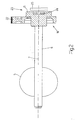
figure 1 is a frontal, diagrammatic view of a butterfly valve for an internal combustion engine with parts removed for clarity; and -
figure 2 is a partially sectioned, side view of a shaft of the butterfly valve shaft infigure 1 made according to the manufacturing method object of the present invention; -
figure 3 is a perspective, diagrammatic section view of the shaft infigure 2 ; and -
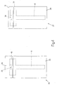
figure 4 is a perspective, diagrammatic view of a step of manufacturing of the shaft infigure 2 . - In
figure 1 ,numeral 1 indicates as a whole a butterfly valve for an internal combustion engine (not shown).Butterfly valve 1 comprises avalve body 2 accommodating anelectric motor 3 and in which a valve seat 4 is obtained which is engaged by a butterfly valve plate 5 (shown infigure 2 ), which is displaced between an opening position and a closing position of the valve seat 4 by effect of the action ofelectric motor 3. Specifically,butterfly valve 5 is keyed on ashaft 6 presenting alongitudinal rotation axis 7 and the closing position by effect of the action ofelectric motor 3 is mechanically coupled toshaft 6 itself by means of agear drive 8. -
Electric motor 3 presents a cylindrical body 9, which is delimited at its base by ametallic plate 10 provided with a pair of through holes (not shown) crossed by twoelectric wires 11 which supply electric energy toelectric motor 3; a correspondinginsulating bushing 12 is arranged between eachelectric wire 11 and the corresponding hole (not shown) inplate 10. The main function ofplate 10 is to allow the fixing ofelectric motor 3 tovalve body 2; for this purpose,plate 10 presents three perforatedradial appendixes 13, through which thecorresponding fastening screws 14 to thevalve body 2 pass. -
Electric motor 3 presents ashaft 15 ending with atoothed wheel 16, which is mechanically connected toshaft 6 by means of an idletoothed wheel 17 interposed betweentoothed wheel 16 and anend gear 18 integral withshaft 6.Toothed wheel 17 presents a first set ofteeth 19 coupled totoothed wheel 16 and a second set ofteeth 20 coupled toend gear 18; the diameter of the first set ofteeth 19 is different from the diameter of the second set ofteeth 20, thustoothed wheel 17 determines a non-unitary transmission ratio.End gear 18 is defined by a full cylindricalcentral body 21 integral withshaft 6 and provided with acircular crown portion 22 presenting a series of teeth coupled totoothed wheel 17. The entire geareddrive 8, i.e.toothed wheel 16,toothed wheel 17 andend gear 18, is normally formed by plastic material. - As shown in
figures 1 and2 ,butterfly valve 1 comprises aposition sensor 23, which is coupled toshaft 6 and which is adapted to detect the angular position ofbutterfly plate 5.Position sensor 23 is of the contactless magnetic type and consists of amagnet 24 integral withshaft 6 and areading device 25 arranged facingmagnet 24 for reading the angular position ofmagnet 24. Specifically,magnet 24 presents a circular shape and is at least partially embedded in full cylindricalcentral body 21 ofend gear 18. As shown in the accompanying figures,magnet 24 is partially embedded within cylindricalcentral body 21 ofend gear 18, i.e. a base wall ofmagnet 24 is in view and thus not covered by cylindricalcentral body 21; according to a different embodiment (not shown),magnet 24 is completely embedded within cylindricalcentral body 21 ofend gear 18,i.e. magnet 24 is completely concealed inside cylindricalcentral body 21. - As shown in
figure 4 ,shaft 6 andend gear 18 are formed together by plastic material (technopolymers) by injection; consequently,shaft 6 andend gear 18 are monolithic, i.e. seamlessly formed by a same material. The manufacturing ofshaft 6 andend gear 18 contemplates the use of afirst mold 26, which negatively reproduces the shape ofshaft 6 and ofend gear 18 and in which molten plastic material is injected to formshaft 6 andend gear 18.First mold 26 is shaped so as to define a circular seat orcavity 28 inend gear 18 intended to later accommodatemagnet 24 ofposition sensor 23. - Subsequently,
shaft 6 and end gear 18 (or only end gear 18) are at least partially inserted in asecond mold 27, which negatively reproduces the shape ofmagnet 24 ofposition sensor 23 and in which a molten magnetic polymer (e.g. neodymium polymer) is injected to formmagnet 24. Obviously,second cavity 27 embraces (surrounds) circular seat orcavity 28 intended to accommodatemagnet 24 ofposition sensor 23. The magnetic polymer consists of small magnetic metallic material particles (powder) and a plastic binding matrix; in order to inject the magnetic polymer, the plastic bounding matrix is molten, while the small magnetic metallic material particles (powder) remain solid and suspended in the molten plastic matrix. - According to a preferred embodiment, the injection of the molten magnetic polymer for forming
magnet 24 is performed radially (i.e. perpendicularly to longitudinal rotation axis 7) from at least two different injection points symmetrically arranged aboutlongitudinal rotation axis 7 and positioned on the external perimeter ofseat 28 formagnet 24 in order to optimize the position of the plastic material flow seam line by forcing it into the volume ofmagnet 24. In other words, the molten magnetic polymer is injected along a radial direction from at least two different injection points for formingmagnet 24; the number of injection points is at least equal to two and more generally is comprised between two and four. In virtue of the use of a radial injection from several different invention points of the molten magnetic polymer from several different injection points, the seam lines ofmagnet 24 are arranged insidemagnet 24 and thusmagnet 24 itself is particularly homogenous; in virtue of the considerable homogeneousness of the injected material, the magnetic field flux lines generated bymagnet 24 after magnetizing are uniform and thus the reading ofposition sensor 23 is very accurate. - Finally,
magnet 24 is magnetized by arrangingmagnet 24 inside an appropriately oriented field and varying the intensity of the magnetic field so as to makemagnet 24 perform a hysteresis cycle. Normally,magnet 24 is magnetized after the injection ofmagnet 24 itself; alternatively,magnet 24 could be magnetized during the injection, for example by providingsecond mold 27 with a coil in which an electric current passes in use. - According to a possible embodiment, two
molds molds 26 and 27) and two correspondingcharacteristic parts 30 and 31 (i.e. proper of eachmold 26 and 27). In other words,first mold 26 consists of acommon part 29 and propercharacteristic part 30, whilesecond mold 27 consists ofcommon part 28 and propercharacteristic part 31. - In other words,
shaft 6,end gear 18 andmagnet 24 are manufactured by means of a two-step injection or sequential injection of a plasticmaterial forming shaft 6 andend gear 18 and a magneticpolymer forming magnet 24. - In the above-described manufacturing method,
shaft 6 is firstly made along withend gear 18 andmagnet 24 is made later; according to a different embodiment,magnet 24 may be made first andend gear 18 later. - The above-described manufacturing method of
shaft 6,end gear 18 andmagnet 24 is particularly advantageous because it allows to contain manufacturing times and costs and concurrently to obtain a highly integrated component and a considerable manufacturing precision, specifically in the positioning ofmagnet 24 with respect toshaft 6. Specifically, the containment of manufacturing times and costs is obtained in virtue of the fact that the above-described manufacturing method ofshaft 6,end gear 18 andmagnet 24 may be simply and completely automated. - The above-described manufacturing method may obviously be used to make a shaft-magnetic rotor set for any type of air flow rate adjustment valve for an internal combustion engine; for example, such manufacturing method could be used to make a shaft-magnetic rotor set of a choking valve of a swirl system or a tumble system for an intake manifold of an internal combustion engine.
Claims (10)
- A manufacturing method of a shaft (6) provided with a magnet (24) for an air flow rate adjustment valve (1) in an internal combustion engine; the method comprises the steps of:arranging a first mold (26) which negatively reproduces the shape of the shaft (6) and determines the formation of a seat (28) for the magnet (24);injecting a molten plastic material inside the mold (26) in order to form the shaft (6) provided with the seat (28) for the magnet (24) by injection molding;arranging a second mold (27) which surrounds the seat (28) for the magnet (24); andinjecting a molten magnetic polymer in the second mold (27) for forming the magnet (24) by injection molding.
- A method according to claim 1, wherein the injection of the molten magnetic polymer for forming the magnet (24) is performed radially from at least two different injection points symmetrically arranged about a longitudinal rotation axis (7) of the shaft.
- A method according to claim 2, wherein the injection points are positioned on the external perimeter of the seat (28) for the magnet (24).
- A method according to claim 2 or 3, wherein the number of injection points is comprised between two and four.
- A method according to one of the claims from 1 to 4 and comprising the further step of magnetizing the magnet (24) by arranging the magnet (24) inside an appropriately oriented magnetic field and by varying the intensity of the magnetic field so as to make the magnet (24) perform at least one hysteresis cycle.
- A method according to claim 5, wherein the magnet (24) is magnetized at the end of the molten magnetic polymer casting.
- A method according to claim 5, wherein the magnet (24) is magnetized during the molten magnetic polymer casting.
- A method according to one of the claims from 1 to 7, wherein the shaft (6) is provided with an end gear (18), which is defined by a cylindrical central body (21) integral with the shaft (6) and provided with at least one circular crown portion (22) presenting a series of coupled teeth; magnet (24) is at least partially embedded in the cylindrical central body (21) of the end gear (18).
- A method according to one of the claims from 1 to 8, wherein the magnet (24) constitutes the rotating part of a position sensor (23) of contactless magnetic type adapted to read the angular position of shaft (6).
- A method according to one of the claims from 1 to 9, wherein the two molds (26, 27) present a common part (29) and two corresponding characteristic parts (30, 31).
Priority Applications (6)
| Application Number | Priority Date | Filing Date | Title |
|---|---|---|---|
| AT07425348T ATE438839T1 (en) | 2007-06-04 | 2007-06-04 | SHAFT WITH MAGNET FOR A FLOW-CONTROLING VALVE OF AN INTERNAL COMBUSTION ENGINE |
| EP07425348A EP2000781B2 (en) | 2007-06-04 | 2007-06-04 | A manufacturing method of a shaft provided with a magnet for an air flow rate adjustment valve in an internal combustion engine |
| DE602007001880T DE602007001880D1 (en) | 2007-06-04 | 2007-06-04 | Shaft with magnet for a flow control valve of an internal combustion engine |
| US12/133,235 US20080296804A1 (en) | 2007-06-04 | 2008-06-04 | Shaft provided with a magnet for an air flow rate adjustment valve in an internal combustion engine |
| CN2008101099127A CN101323161B (en) | 2007-06-04 | 2008-06-04 | Shaft provided with a magnet for an air flow rate adjustment valve in an internal combustion engine |
| BRPI0802196-1A BRPI0802196B1 (en) | 2007-06-04 | 2008-06-04 | axis manufacturing method |
Applications Claiming Priority (1)
| Application Number | Priority Date | Filing Date | Title |
|---|---|---|---|
| EP07425348A EP2000781B2 (en) | 2007-06-04 | 2007-06-04 | A manufacturing method of a shaft provided with a magnet for an air flow rate adjustment valve in an internal combustion engine |
Publications (3)
| Publication Number | Publication Date |
|---|---|
| EP2000781A1 true EP2000781A1 (en) | 2008-12-10 |
| EP2000781B1 EP2000781B1 (en) | 2009-08-05 |
| EP2000781B2 EP2000781B2 (en) | 2013-03-13 |
Family
ID=38521163
Family Applications (1)
| Application Number | Title | Priority Date | Filing Date |
|---|---|---|---|
| EP07425348A Active EP2000781B2 (en) | 2007-06-04 | 2007-06-04 | A manufacturing method of a shaft provided with a magnet for an air flow rate adjustment valve in an internal combustion engine |
Country Status (6)
| Country | Link |
|---|---|
| US (1) | US20080296804A1 (en) |
| EP (1) | EP2000781B2 (en) |
| CN (1) | CN101323161B (en) |
| AT (1) | ATE438839T1 (en) |
| BR (1) | BRPI0802196B1 (en) |
| DE (1) | DE602007001880D1 (en) |
Families Citing this family (7)
| Publication number | Priority date | Publication date | Assignee | Title |
|---|---|---|---|---|
| JP2011156664A (en) * | 2010-01-29 | 2011-08-18 | Showa Corp | Method and apparatus for manufacturing power transmission system molding |
| BR112014002889A2 (en) * | 2011-08-08 | 2017-03-01 | Husqvarna Ab | magnet holder for use in a choke position sensor and method of manufacture |
| DE102011119514B4 (en) * | 2011-11-26 | 2020-11-12 | Gm Tec Industries Holding Gmbh | Gear with permanently connected drive shaft |
| CA2891752A1 (en) * | 2012-11-30 | 2014-06-05 | Petrolvalves S.R.L. | Continuous magnetic motion position indicator |
| DE202017106253U1 (en) * | 2017-10-16 | 2019-01-17 | Flaco-Geräte GmbH | Oval gear |
| CN110360012A (en) * | 2019-08-09 | 2019-10-22 | 马瑞利(中国)有限公司 | A kind of electronic throttle output shaft assembly and manufacturing method |
| JP2022012529A (en) * | 2020-07-01 | 2022-01-17 | 株式会社デンソー | Rotatable component and method for manufacturing rotatable component |
Citations (6)
| Publication number | Priority date | Publication date | Assignee | Title |
|---|---|---|---|---|
| US4364011A (en) * | 1979-05-16 | 1982-12-14 | Ransome Hoffmann Pollard Ltd. | Mechanical assemblies employing sensing means for sensing motion or position |
| FR2583514A1 (en) * | 1985-06-18 | 1986-12-19 | Peugeot | Device for position measurement of a component in motion using magnetic plastics and its method of production |
| US5427514A (en) * | 1988-04-28 | 1995-06-27 | Yazaki Corporation | Magnetic plastic rotor disk manufacturing apparatus |
| EP1028239A2 (en) * | 1999-02-10 | 2000-08-16 | CTS Corporation | Throttle valve position sensor |
| US20010002599A1 (en) * | 1999-01-29 | 2001-06-07 | Ab Elektronik Gmbh | Hall effect rotation sensor for a throttle valve unit |
| US20050028871A1 (en) * | 2003-08-04 | 2005-02-10 | Mitsubishi Denki Kabushiki Kaisha | Intake air control apparatus for an engine |
Family Cites Families (7)
| Publication number | Priority date | Publication date | Assignee | Title |
|---|---|---|---|---|
| US4327346A (en) * | 1979-02-28 | 1982-04-27 | Tdk Electronics Co., Ltd. | Anisotropic polymeric magnet in the tubular form and process for producing the same |
| US6278269B1 (en) * | 1999-03-08 | 2001-08-21 | Allegro Microsystems, Inc. | Magnet structure |
| US6498311B1 (en) * | 2001-06-29 | 2002-12-24 | Microsoft Corporation | Multi-layer keys with translucent outer layer |
| DE10137771A1 (en) † | 2001-08-02 | 2003-02-20 | Bosch Gmbh Robert | Throttle valve unit with integrated throttle valve |
| JP2003130045A (en) * | 2001-10-25 | 2003-05-08 | Pentax Corp | Bearing structure |
| JP2005048671A (en) * | 2003-07-29 | 2005-02-24 | Mitsubishi Electric Corp | Engine intake control device |
| DE102004020734A1 (en) † | 2004-04-27 | 2005-11-24 | Windhorst Beteiligungsgesellschaft Mbh | Measuring system for angular positions based on magnets uses a magneto-resistive sensor to detect permanent magnet field components in interlinked bridge circuits |
-
2007
- 2007-06-04 AT AT07425348T patent/ATE438839T1/en not_active IP Right Cessation
- 2007-06-04 DE DE602007001880T patent/DE602007001880D1/en active Active
- 2007-06-04 EP EP07425348A patent/EP2000781B2/en active Active
-
2008
- 2008-06-04 BR BRPI0802196-1A patent/BRPI0802196B1/en active IP Right Grant
- 2008-06-04 CN CN2008101099127A patent/CN101323161B/en active Active
- 2008-06-04 US US12/133,235 patent/US20080296804A1/en not_active Abandoned
Patent Citations (6)
| Publication number | Priority date | Publication date | Assignee | Title |
|---|---|---|---|---|
| US4364011A (en) * | 1979-05-16 | 1982-12-14 | Ransome Hoffmann Pollard Ltd. | Mechanical assemblies employing sensing means for sensing motion or position |
| FR2583514A1 (en) * | 1985-06-18 | 1986-12-19 | Peugeot | Device for position measurement of a component in motion using magnetic plastics and its method of production |
| US5427514A (en) * | 1988-04-28 | 1995-06-27 | Yazaki Corporation | Magnetic plastic rotor disk manufacturing apparatus |
| US20010002599A1 (en) * | 1999-01-29 | 2001-06-07 | Ab Elektronik Gmbh | Hall effect rotation sensor for a throttle valve unit |
| EP1028239A2 (en) * | 1999-02-10 | 2000-08-16 | CTS Corporation | Throttle valve position sensor |
| US20050028871A1 (en) * | 2003-08-04 | 2005-02-10 | Mitsubishi Denki Kabushiki Kaisha | Intake air control apparatus for an engine |
Also Published As
| Publication number | Publication date |
|---|---|
| BRPI0802196A2 (en) | 2009-04-07 |
| ATE438839T1 (en) | 2009-08-15 |
| CN101323161A (en) | 2008-12-17 |
| BRPI0802196B1 (en) | 2020-10-27 |
| EP2000781B1 (en) | 2009-08-05 |
| US20080296804A1 (en) | 2008-12-04 |
| DE602007001880D1 (en) | 2009-09-17 |
| EP2000781B2 (en) | 2013-03-13 |
| CN101323161B (en) | 2012-10-24 |
Similar Documents
| Publication | Publication Date | Title |
|---|---|---|
| EP2000781B2 (en) | A manufacturing method of a shaft provided with a magnet for an air flow rate adjustment valve in an internal combustion engine | |
| BRPI0802257B1 (en) | axis manufacturing method | |
| US8049493B2 (en) | Resin-molded products and methods of manufacturing the same | |
| JP4433886B2 (en) | Rotation angle detector | |
| US7063303B2 (en) | Throttle apparatus having axial displacement restricting structure | |
| EP1612387A2 (en) | Throttle device for internal combustion engine | |
| JP2008298083A (en) | Method of adjusting opening of throttle body opener | |
| JP4103721B2 (en) | Method of forming throttle device for internal combustion engine | |
| JP2005054627A (en) | Throttle body | |
| JP2007315184A (en) | Electronically controlled throttle unit | |
| JP2013195262A (en) | Rotation angle detection device | |
| EP3842734A1 (en) | Electronically controlled throttle device for engine | |
| US6886800B2 (en) | Production method for the rotor component of a position sensor of a butterfly valve for an internal combustion engine | |
| EP2918814A1 (en) | Assembly structure for non-magnetic body | |
| CN103717857B (en) | Magnet holder in throttle valve position sensor, the magnet holder in the level sensor of angle and their manufacture method | |
| US6325045B1 (en) | Device for controlling intake air quantity of combustion engine and a method of producing the same | |
| JP6070242B2 (en) | Method for producing insert resin molded body | |
| US8209863B2 (en) | Methods of manufacturing rotor core for motor-driven valve, rotor feed screw and rotor | |
| JP2021167094A (en) | Manufacturing method of motor | |
| JP4424179B2 (en) | Method of manufacturing throttle device for internal combustion engine | |
| JP4972070B2 (en) | Valve unit and manufacturing method thereof | |
| JP2015081510A (en) | Air intake system | |
| JP2004293452A (en) | Throttle device for internal combustion engine | |
| CN205858496U (en) | Air throttle | |
| JP3696732B2 (en) | Electric throttle valve device |
Legal Events
| Date | Code | Title | Description |
|---|---|---|---|
| PUAI | Public reference made under article 153(3) epc to a published international application that has entered the european phase |
Free format text: ORIGINAL CODE: 0009012 |
|
| 17P | Request for examination filed |
Effective date: 20071031 |
|
| AK | Designated contracting states |
Kind code of ref document: A1 Designated state(s): AT BE BG CH CY CZ DE DK EE ES FI FR GB GR HU IE IS IT LI LT LU LV MC MT NL PL PT RO SE SI SK TR |
|
| AX | Request for extension of the european patent |
Extension state: AL BA HR MK RS |
|
| GRAP | Despatch of communication of intention to grant a patent |
Free format text: ORIGINAL CODE: EPIDOSNIGR1 |
|
| GRAC | Information related to communication of intention to grant a patent modified |
Free format text: ORIGINAL CODE: EPIDOSCIGR1 |
|
| RAP1 | Party data changed (applicant data changed or rights of an application transferred) |
Owner name: MAGNETI MARELLI HOLDING S.P.A. |
|
| RAP1 | Party data changed (applicant data changed or rights of an application transferred) |
Owner name: MAGNETI MARELLI S.P.A. |
|
| GRAS | Grant fee paid |
Free format text: ORIGINAL CODE: EPIDOSNIGR3 |
|
| GRAA | (expected) grant |
Free format text: ORIGINAL CODE: 0009210 |
|
| AK | Designated contracting states |
Kind code of ref document: B1 Designated state(s): AT BE BG CH CY CZ DE DK EE ES FI FR GB GR HU IE IS IT LI LT LU LV MC MT NL PL PT RO SE SI SK TR |
|
| REG | Reference to a national code |
Ref country code: GB Ref legal event code: FG4D |
|
| REG | Reference to a national code |
Ref country code: CH Ref legal event code: EP |
|
| AKX | Designation fees paid |
Designated state(s): AT BE BG CH CY CZ DE DK EE ES FI FR GB GR HU IE IS IT LI LT LU LV MC MT NL PL PT RO SE SI SK TR |
|
| REG | Reference to a national code |
Ref country code: IE Ref legal event code: FG4D |
|
| REF | Corresponds to: |
Ref document number: 602007001880 Country of ref document: DE Date of ref document: 20090917 Kind code of ref document: P |
|
| LTIE | Lt: invalidation of european patent or patent extension |
Effective date: 20090805 |
|
| PG25 | Lapsed in a contracting state [announced via postgrant information from national office to epo] |
Ref country code: FI Free format text: LAPSE BECAUSE OF FAILURE TO SUBMIT A TRANSLATION OF THE DESCRIPTION OR TO PAY THE FEE WITHIN THE PRESCRIBED TIME-LIMIT Effective date: 20090805 Ref country code: SE Free format text: LAPSE BECAUSE OF FAILURE TO SUBMIT A TRANSLATION OF THE DESCRIPTION OR TO PAY THE FEE WITHIN THE PRESCRIBED TIME-LIMIT Effective date: 20090805 Ref country code: AT Free format text: LAPSE BECAUSE OF FAILURE TO SUBMIT A TRANSLATION OF THE DESCRIPTION OR TO PAY THE FEE WITHIN THE PRESCRIBED TIME-LIMIT Effective date: 20090805 Ref country code: LT Free format text: LAPSE BECAUSE OF FAILURE TO SUBMIT A TRANSLATION OF THE DESCRIPTION OR TO PAY THE FEE WITHIN THE PRESCRIBED TIME-LIMIT Effective date: 20090805 Ref country code: IS Free format text: LAPSE BECAUSE OF FAILURE TO SUBMIT A TRANSLATION OF THE DESCRIPTION OR TO PAY THE FEE WITHIN THE PRESCRIBED TIME-LIMIT Effective date: 20091205 Ref country code: ES Free format text: LAPSE BECAUSE OF FAILURE TO SUBMIT A TRANSLATION OF THE DESCRIPTION OR TO PAY THE FEE WITHIN THE PRESCRIBED TIME-LIMIT Effective date: 20091116 |
|
| NLV1 | Nl: lapsed or annulled due to failure to fulfill the requirements of art. 29p and 29m of the patents act | ||
| PG25 | Lapsed in a contracting state [announced via postgrant information from national office to epo] |
Ref country code: NL Free format text: LAPSE BECAUSE OF FAILURE TO SUBMIT A TRANSLATION OF THE DESCRIPTION OR TO PAY THE FEE WITHIN THE PRESCRIBED TIME-LIMIT Effective date: 20090805 Ref country code: LV Free format text: LAPSE BECAUSE OF FAILURE TO SUBMIT A TRANSLATION OF THE DESCRIPTION OR TO PAY THE FEE WITHIN THE PRESCRIBED TIME-LIMIT Effective date: 20090805 Ref country code: PL Free format text: LAPSE BECAUSE OF FAILURE TO SUBMIT A TRANSLATION OF THE DESCRIPTION OR TO PAY THE FEE WITHIN THE PRESCRIBED TIME-LIMIT Effective date: 20090805 Ref country code: SI Free format text: LAPSE BECAUSE OF FAILURE TO SUBMIT A TRANSLATION OF THE DESCRIPTION OR TO PAY THE FEE WITHIN THE PRESCRIBED TIME-LIMIT Effective date: 20090805 |
|
| PG25 | Lapsed in a contracting state [announced via postgrant information from national office to epo] |
Ref country code: PT Free format text: LAPSE BECAUSE OF FAILURE TO SUBMIT A TRANSLATION OF THE DESCRIPTION OR TO PAY THE FEE WITHIN THE PRESCRIBED TIME-LIMIT Effective date: 20091205 Ref country code: BG Free format text: LAPSE BECAUSE OF FAILURE TO SUBMIT A TRANSLATION OF THE DESCRIPTION OR TO PAY THE FEE WITHIN THE PRESCRIBED TIME-LIMIT Effective date: 20091105 |
|
| PG25 | Lapsed in a contracting state [announced via postgrant information from national office to epo] |
Ref country code: EE Free format text: LAPSE BECAUSE OF FAILURE TO SUBMIT A TRANSLATION OF THE DESCRIPTION OR TO PAY THE FEE WITHIN THE PRESCRIBED TIME-LIMIT Effective date: 20090805 Ref country code: DK Free format text: LAPSE BECAUSE OF FAILURE TO SUBMIT A TRANSLATION OF THE DESCRIPTION OR TO PAY THE FEE WITHIN THE PRESCRIBED TIME-LIMIT Effective date: 20090805 Ref country code: CZ Free format text: LAPSE BECAUSE OF FAILURE TO SUBMIT A TRANSLATION OF THE DESCRIPTION OR TO PAY THE FEE WITHIN THE PRESCRIBED TIME-LIMIT Effective date: 20090805 Ref country code: RO Free format text: LAPSE BECAUSE OF FAILURE TO SUBMIT A TRANSLATION OF THE DESCRIPTION OR TO PAY THE FEE WITHIN THE PRESCRIBED TIME-LIMIT Effective date: 20090805 |
|
| PLBI | Opposition filed |
Free format text: ORIGINAL CODE: 0009260 |
|
| PG25 | Lapsed in a contracting state [announced via postgrant information from national office to epo] |
Ref country code: SK Free format text: LAPSE BECAUSE OF FAILURE TO SUBMIT A TRANSLATION OF THE DESCRIPTION OR TO PAY THE FEE WITHIN THE PRESCRIBED TIME-LIMIT Effective date: 20090805 |
|
| PLAX | Notice of opposition and request to file observation + time limit sent |
Free format text: ORIGINAL CODE: EPIDOSNOBS2 |
|
| 26 | Opposition filed |
Opponent name: CONTINENTAL AUTOMOTIVE GMBH Effective date: 20100505 |
|
| PG25 | Lapsed in a contracting state [announced via postgrant information from national office to epo] |
Ref country code: BE Free format text: LAPSE BECAUSE OF FAILURE TO SUBMIT A TRANSLATION OF THE DESCRIPTION OR TO PAY THE FEE WITHIN THE PRESCRIBED TIME-LIMIT Effective date: 20090805 |
|
| PLBB | Reply of patent proprietor to notice(s) of opposition received |
Free format text: ORIGINAL CODE: EPIDOSNOBS3 |
|
| PG25 | Lapsed in a contracting state [announced via postgrant information from national office to epo] |
Ref country code: GR Free format text: LAPSE BECAUSE OF FAILURE TO SUBMIT A TRANSLATION OF THE DESCRIPTION OR TO PAY THE FEE WITHIN THE PRESCRIBED TIME-LIMIT Effective date: 20091106 |
|
| PG25 | Lapsed in a contracting state [announced via postgrant information from national office to epo] |
Ref country code: MC Free format text: LAPSE BECAUSE OF NON-PAYMENT OF DUE FEES Effective date: 20100630 |
|
| PLAY | Examination report in opposition despatched + time limit |
Free format text: ORIGINAL CODE: EPIDOSNORE2 |
|
| PG25 | Lapsed in a contracting state [announced via postgrant information from national office to epo] |
Ref country code: IT Free format text: LAPSE BECAUSE OF NON-PAYMENT OF DUE FEES Effective date: 20100604 |
|
| PG25 | Lapsed in a contracting state [announced via postgrant information from national office to epo] |
Ref country code: IE Free format text: LAPSE BECAUSE OF NON-PAYMENT OF DUE FEES Effective date: 20100604 Ref country code: MT Free format text: LAPSE BECAUSE OF FAILURE TO SUBMIT A TRANSLATION OF THE DESCRIPTION OR TO PAY THE FEE WITHIN THE PRESCRIBED TIME-LIMIT Effective date: 20090805 |
|
| PLBC | Reply to examination report in opposition received |
Free format text: ORIGINAL CODE: EPIDOSNORE3 |
|
| PLAH | Information related to despatch of examination report in opposition + time limit modified |
Free format text: ORIGINAL CODE: EPIDOSCORE2 |
|
| PLAL | Information related to reply to examination report in opposition modified |
Free format text: ORIGINAL CODE: EPIDOSCORE3 |
|
| REG | Reference to a national code |
Ref country code: CH Ref legal event code: PL |
|
| GBPC | Gb: european patent ceased through non-payment of renewal fee |
Effective date: 20110604 |
|
| PG25 | Lapsed in a contracting state [announced via postgrant information from national office to epo] |
Ref country code: LI Free format text: LAPSE BECAUSE OF NON-PAYMENT OF DUE FEES Effective date: 20110630 Ref country code: CH Free format text: LAPSE BECAUSE OF NON-PAYMENT OF DUE FEES Effective date: 20110630 |
|
| PG25 | Lapsed in a contracting state [announced via postgrant information from national office to epo] |
Ref country code: GB Free format text: LAPSE BECAUSE OF NON-PAYMENT OF DUE FEES Effective date: 20110604 |
|
| PG25 | Lapsed in a contracting state [announced via postgrant information from national office to epo] |
Ref country code: CY Free format text: LAPSE BECAUSE OF FAILURE TO SUBMIT A TRANSLATION OF THE DESCRIPTION OR TO PAY THE FEE WITHIN THE PRESCRIBED TIME-LIMIT Effective date: 20090805 |
|
| PG25 | Lapsed in a contracting state [announced via postgrant information from national office to epo] |
Ref country code: LU Free format text: LAPSE BECAUSE OF NON-PAYMENT OF DUE FEES Effective date: 20100604 Ref country code: HU Free format text: LAPSE BECAUSE OF FAILURE TO SUBMIT A TRANSLATION OF THE DESCRIPTION OR TO PAY THE FEE WITHIN THE PRESCRIBED TIME-LIMIT Effective date: 20100206 |
|
| PG25 | Lapsed in a contracting state [announced via postgrant information from national office to epo] |
Ref country code: TR Free format text: LAPSE BECAUSE OF FAILURE TO SUBMIT A TRANSLATION OF THE DESCRIPTION OR TO PAY THE FEE WITHIN THE PRESCRIBED TIME-LIMIT Effective date: 20090805 |
|
| PUAH | Patent maintained in amended form |
Free format text: ORIGINAL CODE: 0009272 |
|
| STAA | Information on the status of an ep patent application or granted ep patent |
Free format text: STATUS: PATENT MAINTAINED AS AMENDED |
|
| 27A | Patent maintained in amended form |
Effective date: 20130313 |
|
| AK | Designated contracting states |
Kind code of ref document: B2 Designated state(s): AT BE BG CH CY CZ DE DK EE ES FI FR GB GR HU IE IS IT LI LT LU LV MC MT NL PL PT RO SE SI SK TR |
|
| REG | Reference to a national code |
Ref country code: DE Ref legal event code: R102 Ref document number: 602007001880 Country of ref document: DE Effective date: 20130313 |
|
| PG25 | Lapsed in a contracting state [announced via postgrant information from national office to epo] |
Ref country code: LV Free format text: LAPSE BECAUSE OF FAILURE TO SUBMIT A TRANSLATION OF THE DESCRIPTION OR TO PAY THE FEE WITHIN THE PRESCRIBED TIME-LIMIT Effective date: 20130313 |
|
| REG | Reference to a national code |
Ref country code: FR Ref legal event code: PLFP Year of fee payment: 10 |
|
| REG | Reference to a national code |
Ref country code: FR Ref legal event code: PLFP Year of fee payment: 11 |
|
| REG | Reference to a national code |
Ref country code: FR Ref legal event code: PLFP Year of fee payment: 12 |
|
| PGFP | Annual fee paid to national office [announced via postgrant information from national office to epo] |
Ref country code: IT Payment date: 20230523 Year of fee payment: 17 Ref country code: FR Payment date: 20230523 Year of fee payment: 17 Ref country code: DE Payment date: 20230523 Year of fee payment: 17 |