EP2000749A2 - Solar energy collector and method for manufacturing of a reflector profile - Google Patents
Solar energy collector and method for manufacturing of a reflector profile Download PDFInfo
- Publication number
- EP2000749A2 EP2000749A2 EP08396009A EP08396009A EP2000749A2 EP 2000749 A2 EP2000749 A2 EP 2000749A2 EP 08396009 A EP08396009 A EP 08396009A EP 08396009 A EP08396009 A EP 08396009A EP 2000749 A2 EP2000749 A2 EP 2000749A2
- Authority
- EP
- European Patent Office
- Prior art keywords
- pipe
- collector
- profile
- parabolic
- reflecting device
- Prior art date
- Legal status (The legal status is an assumption and is not a legal conclusion. Google has not performed a legal analysis and makes no representation as to the accuracy of the status listed.)
- Withdrawn
Links
- 238000004519 manufacturing process Methods 0.000 title claims description 7
- 238000000034 method Methods 0.000 title claims 5
- 239000007788 liquid Substances 0.000 claims abstract description 19
- 239000011521 glass Substances 0.000 claims abstract description 14
- 230000005855 radiation Effects 0.000 claims abstract description 7
- 238000005452 bending Methods 0.000 claims abstract description 5
- 239000003351 stiffener Substances 0.000 claims abstract description 4
- 239000012530 fluid Substances 0.000 claims abstract description 3
- 239000000463 material Substances 0.000 claims description 6
- 238000005259 measurement Methods 0.000 claims description 3
- 230000009286 beneficial effect Effects 0.000 claims description 2
- XAGFODPZIPBFFR-UHFFFAOYSA-N aluminium Chemical compound [Al] XAGFODPZIPBFFR-UHFFFAOYSA-N 0.000 description 2
- 229910052782 aluminium Inorganic materials 0.000 description 2
- 239000004411 aluminium Substances 0.000 description 2
- VYPSYNLAJGMNEJ-UHFFFAOYSA-N Silicium dioxide Chemical compound O=[Si]=O VYPSYNLAJGMNEJ-UHFFFAOYSA-N 0.000 description 1
- 238000000576 coating method Methods 0.000 description 1
- 238000010276 construction Methods 0.000 description 1
- 230000000694 effects Effects 0.000 description 1
- 238000009413 insulation Methods 0.000 description 1
- 239000012212 insulator Substances 0.000 description 1
- 230000000750 progressive effect Effects 0.000 description 1
- 238000010792 warming Methods 0.000 description 1
Images


Classifications
-
- F—MECHANICAL ENGINEERING; LIGHTING; HEATING; WEAPONS; BLASTING
- F24—HEATING; RANGES; VENTILATING
- F24S—SOLAR HEAT COLLECTORS; SOLAR HEAT SYSTEMS
- F24S10/00—Solar heat collectors using working fluids
- F24S10/40—Solar heat collectors using working fluids in absorbing elements surrounded by transparent enclosures, e.g. evacuated solar collectors
- F24S10/45—Solar heat collectors using working fluids in absorbing elements surrounded by transparent enclosures, e.g. evacuated solar collectors the enclosure being cylindrical
-
- F—MECHANICAL ENGINEERING; LIGHTING; HEATING; WEAPONS; BLASTING
- F24—HEATING; RANGES; VENTILATING
- F24S—SOLAR HEAT COLLECTORS; SOLAR HEAT SYSTEMS
- F24S10/00—Solar heat collectors using working fluids
- F24S10/70—Solar heat collectors using working fluids the working fluids being conveyed through tubular absorbing conduits
-
- F—MECHANICAL ENGINEERING; LIGHTING; HEATING; WEAPONS; BLASTING
- F24—HEATING; RANGES; VENTILATING
- F24S—SOLAR HEAT COLLECTORS; SOLAR HEAT SYSTEMS
- F24S23/00—Arrangements for concentrating solar-rays for solar heat collectors
- F24S23/70—Arrangements for concentrating solar-rays for solar heat collectors with reflectors
- F24S23/71—Arrangements for concentrating solar-rays for solar heat collectors with reflectors with parabolic reflective surfaces
-
- Y—GENERAL TAGGING OF NEW TECHNOLOGICAL DEVELOPMENTS; GENERAL TAGGING OF CROSS-SECTIONAL TECHNOLOGIES SPANNING OVER SEVERAL SECTIONS OF THE IPC; TECHNICAL SUBJECTS COVERED BY FORMER USPC CROSS-REFERENCE ART COLLECTIONS [XRACs] AND DIGESTS
- Y02—TECHNOLOGIES OR APPLICATIONS FOR MITIGATION OR ADAPTATION AGAINST CLIMATE CHANGE
- Y02E—REDUCTION OF GREENHOUSE GAS [GHG] EMISSIONS, RELATED TO ENERGY GENERATION, TRANSMISSION OR DISTRIBUTION
- Y02E10/00—Energy generation through renewable energy sources
- Y02E10/40—Solar thermal energy, e.g. solar towers
- Y02E10/44—Heat exchange systems
Definitions
- the invention relates to a solar energy collector which comprises an oblong profile as a reflecting device, such as a parabolic profile, a collector pipe system which is adjusted to an essentially oblong focal line of the mentioned profile and to which liquid circulation is arranged in such a way that the liquid becomes warm due to the radiation of the sun in the mentioned collector pipe system and the warmed up liquid is directed to release heat energy for example with the help of a heat exchanger for beneficial use.
- parabolic panels as collectors of the solar energy as round panel lenses, in which the energy is taken out centralized from the focal point of the panel and also as oblong series of panels in which case energy is taken out of the pipe which is located to go in the focal line of the reflections in the panels.
- the disadvantage of the round panel is the fact its diameter has to be long so that the needed amount of the panels would not rise too high. Manufacturing of a round panel to be parabolic is expensive because the surface needs to be processed and for example with aluminium it loses its shimmer while being processed. The shimmer needs to be created to it later with some coating method. On the other hand the sizes of plates which are available also limit the size of the panel because manufacturing of the panel is quite impossible by joining several plates to each other in order to form an preform.
- oblong panels have been made of uniform plates which have a panel feature, look for example the publications US 4,296,737 and JP 56155333 .
- the disadvantage of these is the fact that the bodies of the panels are made of some other material than the panel in which case the heat extension of the material has an effect on the panel and changes its parabolic form.
- the parabolic reflecting device is made of a thin plate in order to eliminate the change in profile caused by heat extension to a parabolic form in such a way that the stiffeners which maintain the mentioned profile form are formed of the thin plate itself by creating bendings to it against the profile direction in a vertical direction and in such a way that there is a glass pipe as the outermost pipe of the collector pipe system in which case the rays which are coming from the reflecting device and extending also to the outer edges of this pipe will change their direction essentially due to the light refraction to the inside area of the pipe.
- the reflecting device such as the shimmering thin plate is bent to have a parabolic profile form and a supporting body which maintains its form is formed for the reflecting device with the help of the thin plate itself by bending plate material at the parabolic state of the reflecting device from the longitudinal plate measurement of the device by using flattened handles which extend to the inner or the outer side of the reflecting device.
- the advantage of the collector according to the invention and its manufacturing method is the fact that the collector can be made of a glossy thin plate without damaging its surface and when its body which stiffens and maintains collector form is made of the same material, the heat extension does not misshape at all the parabolic form of the collector.
- the collector becomes very light and turning of it according to the sun can be performed with small power.
- the diameter of the collector pipe which absorbs the radiation in the last resort does not have to be very long, for example 40 mm is enough to be its outer diameter and the rays can be directed to it.
- Disappearing of the heat from the collector pipe can easily be prevented with the help of an insulation arrangement to which a glass pipe as the outermost pipe belongs and another glass pipe inside it belongs and a vacuum between them. Accordingly change of the direction of the rays of the sun towards the inner part of the pipe system occurs due to the light refraction regarding the rays also touching the outermost pipe which improves the operating efficiency of the collecting.
- FIG 1 there is a profile 1 bent to a parabolic arch form from a glossy thin plate which profile is made for example of glossy aluminium plate.
- profile is made for example of glossy aluminium plate.
- stiffening handles 16 which have been pressed from the plate itself at the back side of the profile 1 when the board has firstly been bent to a parabolic arch form. With the help of the handles 16 the profile keeps its shape.
- the collector pipe 2 is located to the focal line of the profile.
- the ends 13 are attached to the profile 1.
- the ends and their extensions are also made of reflecting material and direct rays to the profile 1.
- the collector pipe 2 can be attached to the ends 13. With the help of the ends the whole unit can be supported for example to a body which takes care of the turning of the position of the collector according to the sun.
- FIG 3 a structure of a collector pipe system 2 is shown to which two glass pipes 4 and 6 belong as the outermost pipes.
- the glass of the outermost putki 4 is glass which lets long-wave heat radiation through, like quartz glass.
- the inner glass pipe 6 is a Duran-pipe to which the rays which have the longest waves are being absorbed.
- a circle - in other words the diagonal accuracy is shown with which accuracy the rays coming near the collector pipe still change their direction in the glass pipes 4 and 6 due to the light refraction at least to a liquid room 8 which is outside the black pipe 9.
- the actual black pipe 9 has still an essentially shorter diameter and it also can have it because the radiation energy either stays in the black pipe 9 or in the liquid 8 which is around it while warming up them.
- the collector pipe 2 in which the pipes 4 and 6 are the glass pipes, the pipe 9 is the black pipe and the inlet pipe 11 is the pipe for the cold liquid to be fed within it.
- the part 18 can be opened a little as parts 18a and 18b in such a way that the press 19 can be pressed to the thin plate between the parts and downwards [as much as] the measurement of the fold is, in the step 4.
- the press 19 is drawn away and the parts a and b of the opposite part 20 are pressed together in which case the fold becomes squeezed, in the steps 6 and 7.
- the tools are opened and are moved to the location of the new handle 16 to be formed.
- the handles 16 can be made, if wanted, also inside the profile, but the better option is to make them outside the profile.
- the stiffening ribbing 16 can be of a uniform height or their height can be lowered at the location of the edges of the profile 1. This can be achieved with the help of the shape of the lower end of the press 19.
Landscapes
- Engineering & Computer Science (AREA)
- Physics & Mathematics (AREA)
- Life Sciences & Earth Sciences (AREA)
- Sustainable Development (AREA)
- Sustainable Energy (AREA)
- Thermal Sciences (AREA)
- Chemical & Material Sciences (AREA)
- Combustion & Propulsion (AREA)
- Mechanical Engineering (AREA)
- General Engineering & Computer Science (AREA)
- Optical Elements Other Than Lenses (AREA)
Abstract
A collector of the solar energy (1, 2) which comprises an oblong profile as a reflecting device, such as a parabolic profile (1), a collector pipe system (2) which is adjusted to be at the oblong focal line of the mentioned profile to which collector pipeline fluid circulation is arranged in such a way that the liquid becomes warm due to the radiation of the sun in the mentioned collector pipe system. The parabolic reflecting device (1) is made of a thin plate to a parabolic form in order to eliminate the profile change due to heat extension in such a way that the stiffeners (16) which maintain the mentioned profile form are formed of a thin plate itself by creating bendings to it against the profile direction in a vertical direction and that there is a glass pipe (4) as the outermost pipe of the collector pipe system (2) in which case the rays which come from the reflecting device even to the outer edges of this pipe change their direction essentially due to the light refraction inside of the pipe (4).
Description
- The invention relates to a solar energy collector which comprises an oblong profile as a reflecting device, such as a parabolic profile, a collector pipe system which is adjusted to an essentially oblong focal line of the mentioned profile and to which liquid circulation is arranged in such a way that the liquid becomes warm due to the radiation of the sun in the mentioned collector pipe system and the warmed up liquid is directed to release heat energy for example with the help of a heat exchanger for beneficial use.
- Previously are known parabolic panels as collectors of the solar energy as round panel lenses, in which the energy is taken out centralized from the focal point of the panel and also as oblong series of panels in which case energy is taken out of the pipe which is located to go in the focal line of the reflections in the panels.
- The disadvantage of the round panel is the fact its diameter has to be long so that the needed amount of the panels would not rise too high. Manufacturing of a round panel to be parabolic is expensive because the surface needs to be processed and for example with aluminium it loses its shimmer while being processed. The shimmer needs to be created to it later with some coating method. On the other hand the sizes of plates which are available also limit the size of the panel because manufacturing of the panel is quite impossible by joining several plates to each other in order to form an preform.
- The disadvantage of oblong, parabolic panels is the fact that they stay parabolic and that they even create it. Parabolic profiles have been made for example out of several straight parallel lines of panels which all have been directed to the collector pipe. With this solution an accurate radiation concentration cannot be achieved to the collector pipe or then the diameter of the collector pipe then has to be longer than needed.
- Also parabolic, oblong panels have been made of uniform plates which have a panel feature, look for example the publications
US 4,296,737 andJP 56155333 - In order to eliminate the above mentioned disadvantages a new collector of the solar energy has been developed with the help of which the faults of the previous solutions can essentially be eliminated and it is characteristic for the collector according to the invention that the parabolic reflecting device is made of a thin plate in order to eliminate the change in profile caused by heat extension to a parabolic form in such a way that the stiffeners which maintain the mentioned profile form are formed of the thin plate itself by creating bendings to it against the profile direction in a vertical direction and in such a way that there is a glass pipe as the outermost pipe of the collector pipe system in which case the rays which are coming from the reflecting device and extending also to the outer edges of this pipe will change their direction essentially due to the light refraction to the inside area of the pipe.
- It is characteristic for the manufacturing method of the collector according to the invention that the reflecting device, such as the shimmering thin plate is bent to have a parabolic profile form and a supporting body which maintains its form is formed for the reflecting device with the help of the thin plate itself by bending plate material at the parabolic state of the reflecting device from the longitudinal plate measurement of the device by using flattened handles which extend to the inner or the outer side of the reflecting device.
- The advantage of the collector according to the invention and its manufacturing method is the fact that the collector can be made of a glossy thin plate without damaging its surface and when its body which stiffens and maintains collector form is made of the same material, the heat extension does not misshape at all the parabolic form of the collector. The collector becomes very light and turning of it according to the sun can be performed with small power. When the parabolic form of the collector is maintained in all situations, the diameter of the collector pipe which absorbs the radiation in the last resort does not have to be very long, for example 40 mm is enough to be its outer diameter and the rays can be directed to it. Disappearing of the heat from the collector pipe can easily be prevented with the help of an insulation arrangement to which a glass pipe as the outermost pipe belongs and another glass pipe inside it belongs and a vacuum between them. Accordingly change of the direction of the rays of the sun towards the inner part of the pipe system occurs due to the light refraction regarding the rays also touching the outermost pipe which improves the operating efficiency of the collecting.
- In the following the invention is discussed more detailed by referring to the accompanying drawing, in which
- Figure 1
- shows the collector profile and the collector pipe as a side view.
- Figure 2
- shows the solution of the
figure 1 equipped with ends. - Figure 3
- shows the collector pipe system as a crosscut drawing.
- Figure 4
- shows the collector pipe system being partly cut and shown diagonally.
- Figure 5
- shows the collector pipe system as a cut side view.
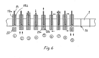
- Figure 6
- shows the progressive manufacturing of the stiffeners of the reflecting profile.
- In the
figure 1 there is a profile 1 bent to a parabolic arch form from a glossy thin plate which profile is made for example of glossy aluminium plate. There arestiffening handles 16 which have been pressed from the plate itself at the back side of the profile 1 when the board has firstly been bent to a parabolic arch form. With the help of thehandles 16 the profile keeps its shape. Thecollector pipe 2 is located to the focal line of the profile. - In the
figure 2 theends 13 are attached to the profile 1. The ends and their extensions are also made of reflecting material and direct rays to the profile 1. Thecollector pipe 2 can be attached to theends 13. With the help of the ends the whole unit can be supported for example to a body which takes care of the turning of the position of the collector according to the sun. - In the
figure 3 a structure of acollector pipe system 2 is shown to which twoglass pipes outermost putki 4 is glass which lets long-wave heat radiation through, like quartz glass. Theinner glass pipe 6 is a Duran-pipe to which the rays which have the longest waves are being absorbed. With the reference number 7 a circle - in other words the diagonal accuracy is shown with which accuracy the rays coming near the collector pipe still change their direction in theglass pipes liquid room 8 which is outside theblack pipe 9. - The actual
black pipe 9 has still an essentially shorter diameter and it also can have it because the radiation energy either stays in theblack pipe 9 or in theliquid 8 which is around it while warming up them. - In the
figure 4 there is the construction of thecollector pipe 2 in which thepipes pipe 9 is the black pipe and theinlet pipe 11 is the pipe for the cold liquid to be fed within it. - In the
figure 5 fluid circulation in thecollector pipe 2 is shown. The liquid is fed through thepipe 11 into theblack pipe 9. Thepipe 11 stops extending inside thepipe 9 already during the first third of the distance. The liquid to be fed exists then in the innermost part of thecollector pipe 2. The liquid can flow freely to the interstice of thepipe 11 and thepipe 9 all the way to the stuffing 14. In this interstice it does not move much and rather functions as an insulator. From the other end of thepipe system 2 through the holes of theblack pipe 9 the liquid flows freely to the ring-like room outside theblack pipe 9 in which it mainly becomes warmer and it flows away to the outer surface of thepipe 11 from the holes of the forepart of theblack pipe 9 and through thatremoval unit 17 which is equipped with athermostat 15. The liquid is circulated with the help of a pump (not shown). Thepipe 11 can extend into theblack pipe 9 to a distance of about 30 - 50 % from the forepart of the pipe. - In the
figure 6 the stiffening of the thin plate profile 1 which is bent to a parabolic form is shown with the help ofhandles 16 from the same thin plate. As tools there are theparts 18 and 19 which are inside the profile and theopposite part 20 which is at the opposite side of the profile are used. With the help of the steps 1 -9 the pleat to be - in other words - theflattened fold 16 is formed while being in a parabolic form outside the profile by folding and stretching the thin plate 1 while maintaining the parabolic form in order to achieve a fold which is about 15 - 20 mm high. The part 18 can be opened a little asparts 18a and 18b in such a way that thepress 19 can be pressed to the thin plate between the parts and downwards [as much as] the measurement of the fold is, in thestep 4. In thestep 5 thepress 19 is drawn away and the parts a and b of theopposite part 20 are pressed together in which case the fold becomes squeezed, in thesteps steps 8 and nine the tools are opened and are moved to the location of thenew handle 16 to be formed. Thehandles 16 can be made, if wanted, also inside the profile, but the better option is to make them outside the profile. - The
stiffening ribbing 16 can be of a uniform height or their height can be lowered at the location of the edges of the profile 1. This can be achieved with the help of the shape of the lower end of thepress 19.
Claims (9)
- A collector of the solar energy (1,2) which comprises an oblong profile as a reflecting device, such as a parabolic profile (1), a collector pipe system (2) which is adjusted to be at the oblong focal line of the mentioned profile to which collector pipeline fluid circulation is arranged in such a way that the liquid becomes warm due to the radiation of the sun in the mentioned collector pipe system and the warmed up liquid is directed to release heat energy for example with the help of a heat exchanger for beneficial use, characterized in that the parabolic reflecting device (1) is made of a thin plate to a parabolic form in order to eliminate the profile change due to heat extension in such a way that the stiffeners (16) which maintain the mentioned profile form are formed of a thin plate itself by creating bendings to it against the profile direction in a vertical direction and that there is a glass pipe (4) as the outermost pipe of the collector pipe system (2) in which case the rays which come from the reflecting device even to the outer edges of this pipe change their direction essentially due to the light refraction inside of the pipe (4).
- A collector of the solar energy according to the claim 1, characterized in that the two outermost pipes (4, 6) of the collector pipe system are made of glass and that there is a vacuum between them.
- A collector of the solar energy according to the claim 1, characterized in that there is a black pipe (9) inside the glass pipe (4) or the inner glass pipe (6) at the both sides of which there is a channel room for the liquid to be warmed.
- A collector of the solar energy according to the claim 1, characterized in that the liquid to be warmed is fed into the black pipe (9) through a pipe (11) which is adjusted into the black pipe which pipe extends into the mentioned pipe (9) for a distance which is at least one third of the length of the black pipe.
- A collector of the solar energy according to the claim 1, characterized in that the warmed up liquid is arranged to be removed from the ring-like room which is outside of the black pipe.
- A collector of the solar energy according to the claim 1, characterized in that there are ends (13) which belong to the reflecting profiles through which or to the support of which the liquid pipe system (2) is adjusted.
- A method for manufacturing a collector of the solar energy in which method solar energy is collected with the help of an oblong reflecting device (1) which comprises a parabolic profile form and with the help of an oblong, collector pipe system (2) in which liquid circulates and which is located to the focal line of the reflecting device, characterized in that the reflecting device, such as a shimmering thin plate is bent to a parabolic profile form and that a supporting body which maintains its shape is formed for the reflecting device with the help of the thin plate itself by bending plate material from the longitudinal plate measurement of the device at the parabolic state of the reflecting device by using flattened ribbings (16) which extend to the inner or the outer side of the reflecting device.
- A method according to the claim 7, characterized in that the ribbing (16) is bent to a standard height covering the whole parabolic arch.
- A method according to the claim 7, characterized in that the ribbing (16) is bent to be higher at the midpoint of the arch than at the edge parts of the arch.
Applications Claiming Priority (1)
| Application Number | Priority Date | Filing Date | Title |
|---|---|---|---|
| FI20070441A FI119892B (en) | 2007-06-04 | 2007-06-04 | Solar energy collector and method for producing a reflector profile |
Publications (1)
| Publication Number | Publication Date |
|---|---|
| EP2000749A2 true EP2000749A2 (en) | 2008-12-10 |
Family
ID=38212300
Family Applications (1)
| Application Number | Title | Priority Date | Filing Date |
|---|---|---|---|
| EP08396009A Withdrawn EP2000749A2 (en) | 2007-06-04 | 2008-06-04 | Solar energy collector and method for manufacturing of a reflector profile |
Country Status (2)
| Country | Link |
|---|---|
| EP (1) | EP2000749A2 (en) |
| FI (1) | FI119892B (en) |
Citations (2)
| Publication number | Priority date | Publication date | Assignee | Title |
|---|---|---|---|---|
| US4296737A (en) | 1979-12-05 | 1981-10-27 | American Science And Engineering, Inc. | Parabolic trough concentrating solar collector |
| JPS56155333A (en) | 1980-04-30 | 1981-12-01 | Haneichi Yoshioka | Solar energy collector |
-
2007
- 2007-06-04 FI FI20070441A patent/FI119892B/en active IP Right Grant
-
2008
- 2008-06-04 EP EP08396009A patent/EP2000749A2/en not_active Withdrawn
Patent Citations (2)
| Publication number | Priority date | Publication date | Assignee | Title |
|---|---|---|---|---|
| US4296737A (en) | 1979-12-05 | 1981-10-27 | American Science And Engineering, Inc. | Parabolic trough concentrating solar collector |
| JPS56155333A (en) | 1980-04-30 | 1981-12-01 | Haneichi Yoshioka | Solar energy collector |
Also Published As
| Publication number | Publication date |
|---|---|
| FI20070441L (en) | 2008-12-05 |
| FI20070441A0 (en) | 2007-06-04 |
| FI119892B (en) | 2009-04-30 |
Similar Documents
| Publication | Publication Date | Title |
|---|---|---|
| CA1039133A (en) | Solar energy collector system | |
| CN101892794B (en) | Solar heat absorption window body | |
| EP2000749A2 (en) | Solar energy collector and method for manufacturing of a reflector profile | |
| DE19709653A1 (en) | Combined solar element of vertical set of solar collector and module | |
| WO2010028806A2 (en) | Solar energy module and solar energy module assembly | |
| CN2205945Y (en) | Solar focusing heat collector with composite paraboloid | |
| EP2226591A1 (en) | Flat vacuum photo-thermal solar panel | |
| US20020073987A1 (en) | Solar energy collector assembly | |
| US10408497B2 (en) | Emergent platform diffuse light concentrating collector | |
| ITBO20100183A1 (en) | SOLAR ENERGY SYSTEM FOR HEATING WATER HEAT | |
| EP3583364B1 (en) | Solar collector with reflecting surfaces | |
| CN218033779U (en) | Distributed solar heating device | |
| WO2007045933A1 (en) | Pergola solar collector system constructed from long heating elements | |
| CN206310761U (en) | A kind of heat collector | |
| AU2002100327A4 (en) | Solar collector | |
| CN206310764U (en) | A kind of light blocking formula solar energy luffer boards | |
| CN218544861U (en) | Solar heat absorption plate core structure | |
| RU217182U1 (en) | solar water heater | |
| CN204478893U (en) | A kind of heat exchange of heat pipe | |
| RU212295U1 (en) | SOLAR ABSORPTION SYSTEM | |
| CN2253449Y (en) | A solar water heater heat absorber | |
| CN211011957U (en) | Photovoltaic shutter structure for storing energy and saving energy based on solar energy after improvement | |
| AU711669B2 (en) | Integral tank solar water heater | |
| CN210801656U (en) | Bracket for balcony wall mounted solar water heater | |
| CN2304868Y (en) | Aluminium dustproof core strip for solar heat collector |
Legal Events
| Date | Code | Title | Description |
|---|---|---|---|
| PUAI | Public reference made under article 153(3) epc to a published international application that has entered the european phase |
Free format text: ORIGINAL CODE: 0009012 |
|
| AK | Designated contracting states |
Kind code of ref document: A2 Designated state(s): AT BE BG CH CY CZ DE DK EE ES FI FR GB GR HR HU IE IS IT LI LT LU LV MC MT NL NO PL PT RO SE SI SK TR |
|
| AX | Request for extension of the european patent |
Extension state: AL BA MK RS |
|
| STAA | Information on the status of an ep patent application or granted ep patent |
Free format text: STATUS: THE APPLICATION IS DEEMED TO BE WITHDRAWN |
|
| 18D | Application deemed to be withdrawn |
Effective date: 20120103 |