EP2000706A2 - System for preventing damage to a vehicle - Google Patents
System for preventing damage to a vehicle Download PDFInfo
- Publication number
- EP2000706A2 EP2000706A2 EP08156946A EP08156946A EP2000706A2 EP 2000706 A2 EP2000706 A2 EP 2000706A2 EP 08156946 A EP08156946 A EP 08156946A EP 08156946 A EP08156946 A EP 08156946A EP 2000706 A2 EP2000706 A2 EP 2000706A2
- Authority
- EP
- European Patent Office
- Prior art keywords
- oil
- processor
- vehicle
- operable
- parameter
- Prior art date
- Legal status (The legal status is an assumption and is not a legal conclusion. Google has not performed a legal analysis and makes no representation as to the accuracy of the status listed.)
- Granted
Links
Images
Classifications
-
- F—MECHANICAL ENGINEERING; LIGHTING; HEATING; WEAPONS; BLASTING
- F16—ENGINEERING ELEMENTS AND UNITS; GENERAL MEASURES FOR PRODUCING AND MAINTAINING EFFECTIVE FUNCTIONING OF MACHINES OR INSTALLATIONS; THERMAL INSULATION IN GENERAL
- F16H—GEARING
- F16H57/00—General details of gearing
- F16H57/04—Features relating to lubrication or cooling or heating
- F16H57/0412—Cooling or heating; Control of temperature
- F16H57/0413—Controlled cooling or heating of lubricant; Temperature control therefor
-
- B—PERFORMING OPERATIONS; TRANSPORTING
- B60—VEHICLES IN GENERAL
- B60R—VEHICLES, VEHICLE FITTINGS, OR VEHICLE PARTS, NOT OTHERWISE PROVIDED FOR
- B60R16/00—Electric or fluid circuits specially adapted for vehicles and not otherwise provided for; Arrangement of elements of electric or fluid circuits specially adapted for vehicles and not otherwise provided for
- B60R16/02—Electric or fluid circuits specially adapted for vehicles and not otherwise provided for; Arrangement of elements of electric or fluid circuits specially adapted for vehicles and not otherwise provided for electric constitutive elements
- B60R16/023—Electric or fluid circuits specially adapted for vehicles and not otherwise provided for; Arrangement of elements of electric or fluid circuits specially adapted for vehicles and not otherwise provided for electric constitutive elements for transmission of signals between vehicle parts or subsystems
- B60R16/0231—Circuits relating to the driving or the functioning of the vehicle
- B60R16/0232—Circuits relating to the driving or the functioning of the vehicle for measuring vehicle parameters and indicating critical, abnormal or dangerous conditions
- B60R16/0234—Circuits relating to the driving or the functioning of the vehicle for measuring vehicle parameters and indicating critical, abnormal or dangerous conditions related to maintenance or repairing of vehicles
-
- F—MECHANICAL ENGINEERING; LIGHTING; HEATING; WEAPONS; BLASTING
- F16—ENGINEERING ELEMENTS AND UNITS; GENERAL MEASURES FOR PRODUCING AND MAINTAINING EFFECTIVE FUNCTIONING OF MACHINES OR INSTALLATIONS; THERMAL INSULATION IN GENERAL
- F16H—GEARING
- F16H57/00—General details of gearing
- F16H57/01—Monitoring wear or stress of gearing elements, e.g. for triggering maintenance
-
- F—MECHANICAL ENGINEERING; LIGHTING; HEATING; WEAPONS; BLASTING
- F16—ENGINEERING ELEMENTS AND UNITS; GENERAL MEASURES FOR PRODUCING AND MAINTAINING EFFECTIVE FUNCTIONING OF MACHINES OR INSTALLATIONS; THERMAL INSULATION IN GENERAL
- F16H—GEARING
- F16H57/00—General details of gearing
- F16H2057/0081—Fixing of, or adapting to transmission failure
-
- F—MECHANICAL ENGINEERING; LIGHTING; HEATING; WEAPONS; BLASTING
- F16—ENGINEERING ELEMENTS AND UNITS; GENERAL MEASURES FOR PRODUCING AND MAINTAINING EFFECTIVE FUNCTIONING OF MACHINES OR INSTALLATIONS; THERMAL INSULATION IN GENERAL
- F16H—GEARING
- F16H57/00—General details of gearing
- F16H57/04—Features relating to lubrication or cooling or heating
- F16H57/0447—Control of lubricant levels, e.g. lubricant level control dependent on temperature
- F16H57/0449—Sensors or indicators for controlling the fluid level
Definitions
- the processor 120 may be a main processor or a plurality of processors operable to communicate with electronics and controllers of the vehicle 100.
- the processor 120 may be part of a public or private communications area network ("CAN").
- the processor 120 may utilize a public electronic communication protocol, such as SAE J 1939 or SAE J 1587, and/or may utilize a proprietary electronic communication protocol or any other type of public or private communication technique.
- the processor 120 may analyze that data and calculate the oil life or wear based on interpolation or extrapolation of the stored data and/or calculation of various equations or mathematical computations.
- Empirical or stored data relating oil quality or life to specific damage to the vehicle 100 may be provided as well.
- the oil life may be displayed on the display 124 in a countdown fashion to warn the driver of when to change the oil and/or when damage to the vehicle 100 is likely to occur.
- the display 124 may show a date and time for a driver to act and/or may show a series of flashing or constant lights. A quality level of the oil wear may also be shown on the display 124.
Landscapes
- Engineering & Computer Science (AREA)
- General Engineering & Computer Science (AREA)
- Mechanical Engineering (AREA)
- Automation & Control Theory (AREA)
- General Details Of Gearings (AREA)
- Control Of Transmission Device (AREA)
- Arrangements For Transmission Of Measured Signals (AREA)
Abstract
Description
- This invention relates to vehicle systems, specifically to such systems used for preventing damage to a vehicle.
- Vehicles, such as cars and trucks, are used on a daily basis for transporting people and commercial cargo as well as providing private and public services. Engines, transmissions, and other vehicle components operate under a wide range of mechanical stress, pressure, and climates. As time passes, the vehicle components experience degradation, such as oil wear, mechanical fractures, increased transmission and non-transmission assembly component temperatures, and/or oil leakage.
- Adding to such degradation, many original equipment manufacturers ("OEMs") of automobile and truck-engines have opted to address increasingly restrictive federal emissions regulations with technology that involves higher engine operating temperatures, higher cooling system temperatures, and/or higher exhaust system temperatures. As a result, driveline components are subject to higher operating temperatures. It is increasingly important to monitor vehicle conditions such as transmission operating temperature, other vehicle component temperature, volume of oil in the transmission, and other features and processes in a vehicle. There is also an increasing need to prevent damage to vehicle components based on these conditions.
- One method for monitoring temperature in a vehicle is to use a sensor to measure, for example, oil-sump temperature and to warn the driver of potentially dangerous temperatures via an indicator. Likewise, transmission oil volume can be monitored using sight-gauges and/or dipsticks. However, these methods provide the driver with limited information (e.g., a simple indicator light) and/or require the driver to stop and inspect the vehicle to prevent damage or further damage to the vehicle. In some cases, significant vehicle damage has already occurred before a driver can stop the vehicle. Accordingly, there is a need for improved methods and systems to prevent damage to a vehicle.
- In a first aspect, a system for preventing damage to a vehicle is provided. A first sensor may be operable to measure a first parameter relating to a transmission component in a vehicle and to provide a first parameter signal indicative of the measured first parameter. A processor may be in communication with the first sensor and operable to receive the first parameter signal from the first sensor. The processor may be further operable to analyze the first parameter signal. The processor may be further operable to initiate a damage prevention process including a reduction of heat generation in the vehicle based on the first parameter.
- In a second aspect, a system for preventing damage to a vehicle is provided. A sensor may be operable to measure an oil parameter and to provide an oil parameter signal indicative of the oil parameter. A processor may be in communication with the sensor that may be operable to receive the oil parameter signal. The processor may be further operable to analyze the oil parameter signal. The processor may be further operable to initiate a damage prevention process in the vehicle based on the oil parameter.
- In a third aspect, a system for preventing damage to a vehicle is provided. A sensor may be operable to measure a vehicle parameter and to provide a vehicle parameter signal indicative of the vehicle parameter. A processor may be in communication with the sensor that may be operable to receive the vehicle parameter signal. A starter interlock signal device may be in communication with the processor. The starter interlock signal device may be operable to receive a starter interlock control signal from the processor. The starter interlock signal device may be further operable to generate a starter interlock signal. The processor may be further operable to analyze the vehicle parameter signal. The processor may be further operable to initiate a damage prevention process based on the vehicle parameter.
- Other systems, methods, features and advantages of the invention will be, or will become, apparent to one with skill in the art upon examination of the following figures and detailed description. It is intended that all such additional systems, methods, features and advantages be included within this description.
- The components in the figures are not necessarily to scale, emphasis instead being placed upon illustrating the principles of the invention. Moreover, in the figures, like referenced numerals designate corresponding parts throughout the different views.
-
Figure 1 is a block diagram illustrating an exemplary embodiment of system for preventing damage to a vehicle. -
Figure 2 is a schematic and a torque flow diagram illustrating an exemplary embodiment of a transmission system used in the system ofFigure 1 . -
Figure 3 is a schematic diagram illustrating an exemplary embodiment of a cooling circuit used in the system ofFigure 1 . -
Figure 4 is a flowchart illustrating an example of a method for preventing damage to a vehicle. -
Figure 5 is a flowchart illustrating another example of a method for preventing damage to a vehicle. -
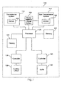
Figure 1 is a block diagram illustrating an exemplary embodiment of a system for preventing damage to avehicle 100. Thevehicle 100 may be a car, bus, truck, or any other known or future vehicle that utilizes an automatic, automated mechanical, or manual transmission. The system for preventing damage may include, but is not limited to, atransmission system 110, anon-transmission system 114, a starterinterlock signal device 154, aprocessor 120, amemory 122, adisplay 124, aflow port controller 128, acooling circuit 130, abaffle controller 140, and abaffle 144. - The
transmission system 110 may include, but is not limited to, a transmission, such as an automatic, automated mechanical, or manual transmission, and asensor 150. Thesensor 150 may be one sensor or a plurality of sensors capable of monitoring or measuring a parameter of a transmission component. For example, thesensor 150 may be a mechanical, electrical, and/or optical sensor that is on or in a vehicle transmission operable to measure angular velocity of a shaft, temperature of transmission oil, level of the transmission oil, and/or volumetric flow rate of the transmission oil. Alternatively, thesensor 150 may be outside of thetransmission system 110. - The
non-transmission system 114 may include, but is not limited to, a non-transmission assembly andsensor 160. The non-transmission assembly may be, for example, an exhaust system, engine, axle, clutch, differential, or brake of thevehicle 100. Thesensor 160 may be one sensor or a plurality of sensors capable of monitoring or measuring a parameter of a non-transmission assembly component. For example, thesensor 160 may be a mechanical, electrical, and/or optical sensor that is on or in the exhaust system of thevehicle 100 operable to measure temperature of the exhaust or the exhaust pipe. Thesensor 160 may be positioned on or in any part of thevehicle 100 and may be operable to measure temperature, velocity, flow rate, and volume of any non-transmission assembly component, such as non-transmission oil, of thevehicle 100. - The starter
interlock signal device 154 may be in communication with thetransmission system 110, thenon-transmission system 114, and/or theprocessor 120. The starterinterlock signal device 154 may be a mechanical and/or electrical switch in thetransmission system 110, thenon-transmission system 114, or any other section of thevehicle 100. For example, the starter interlock signal device may be a neutral switch in thetransmission system 110. Also, the starterinterlock signal device 154 may be in communication with a transmission controller, and the transmission controller may be in communication with or connected with a vehicle wiring harness. Alternatively, the starterinterlock signal device 154 may be directly in communication with the vehicle wiring harness. The starterinterlock signal device 154 may provide a starter interlock signal to drive an engine start enable relay. The starter interlock signal may be a low active signal that is asserted before an engine is allowed to start. - The
display 124 may be any mechanical and/or electronic display positioned for accessible viewing by a driver or passenger of thevehicle 100. For example, thedisplay 124 may be a light emitting diode, ("LED"), display or liquid crystal display, ("LCD"), in or on a dashboard of thevehicle 100. Thedisplay 124 may be capable of showing or illuminating various measurements, such as measurements by thesensor 150 or thesensor 160, calculations or derivations by theprocessor 120, and/or warnings. - The
cooling circuit 130 is operable to cool or transfer heat away from transmission oil of thevehicle 100. Thecooling circuit 130 may also be used for cooling other various liquids or oils that are used in the operation of thevehicle 100. Theflow port controller 128 may be a single mechanical and/or electrical controller or a plurality of such controllers operable to control the operation of thecooling circuit 130. For example, theflow port controller 128 may include, but is not limited to, a solenoid. Various parts of thecooling circuit 130 may be controlled by other mechanical and/or electronic components of thevehicle 100. Also, all or parts of thecooling circuit 130 as well as theflow port controller 128 may be incorporated in thetransmission system 110, thenon-transmission system 114, and/or any other section of thevehicle 100. - The
baffle 144 may be operable to direct or redirect air flow to any component of thevehicle 100, such as components of thetransmission system 110 and/or thenon-transmission system 114. The baffle may be any plate, wall, screen, or other known or future device operable to deflect air or regulate air flow. Thebaffle 144 may be a plurality of such devices. Furthermore, the baffle may be positioned in any part of the vehicle 100 (e.g., the front of the vehicle 100) and may be electronically controlled by thebaffle controller 140. Thebaffle controller 140 may be a single mechanical and/or electrical controller or a plurality of such controllers. - The
processor 120 may be in communication with thememory 122, thesensor 150, thesensor 160, the starterinterlock signal device 154, thedisplay 124, theflow port controller 128, and thebaffle controller 140. Theprocessor 120 may be in communication with any other component of thetransmission system 110 and/or thenon-transmission system 114, such as a transmission controller, other vehicle controllers, or various electronics in thevehicle 100. Thememory 122 may also be in communication with thesensors vehicle 100. Theprocessor 120 and thememory 122 may be in thetransmission system 110, thenon-transmission system 114, and/or any other section of thevehicle 100. Also, theprocessor 120 may be a main processor or a plurality of processors operable to communicate with electronics and controllers of thevehicle 100. For example, theprocessor 120 may be part of a public or private communications area network ("CAN"). Theprocessor 120 may utilize a public electronic communication protocol, such as SAE J 1939 or SAE J 1587, and/or may utilize a proprietary electronic communication protocol or any other type of public or private communication technique. - The system for preventing damage may perform a variety of processes or actions to prevent damage to the
vehicle 100. Damage to thevehicle 100 may include, but is not limited to, bluing or blackening of gears when the temperature in thetransmission system 110 and/or thenon-transmission system 114 rises to a high level, breaking or fracturing of the gears because of high temperatures, oil breakdown, and bearing seizures. Blued or blackened gears may signify that the gear is approaching a physical break or fracture. Other damage may include transmission and/ornon-transmission system 114 breakdown when there is a low level oil or no oil, other vehicle component malfunctions, and/or generation of smoke and fire. - As the
vehicle 100 is moving, thesensor 160 may continuously or periodically measure a non-transmission assembly component in a non-transmission assembly. For example, thesensor 160 may measure temperature of an exhaust pipe or exhaust and/or non-transmission oil and send the temperature data to theprocessor 120. When the temperature of the exhaust pipe or exhaust and/or non-transmission oil reaches or rises above a predetermined threshold, the processor may communicate with thebaffle controller 140 to adjust thebaffle 144 to redirect or route air over the some part of or the entire exhaust system and/or some part of or the entire non-transmission assembly associated with the non-transmission oil to facilitate convective cooling. Similarly, as thevehicle 100 is moving, thesensor 150 may continuously or periodically monitor a transmission component. For example, thesensor 150 may monitor temperature of the transmission oil and send the temperature data to theprocessor 120. When the temperature of the oil reaches or rises above a predetermined threshold, the processor may communicate with thebaffle controller 140 to adjust thebaffle 144 to redirect or route air over the transmission to facilitate convective cooling. Thebaffle 144 may be adjusted to redirect or route air to any component of thevehicle 100 to facilitate convective cooling. - Another example of preventing damage to the
vehicle 100 is to prohibit or discontinue exhaust gas re-circulation, ("EGR"). EGR may include heating the exhaust gas to a high enough temperature to ensure particulate matter oxidation. This heating may occur in the exhaust system, and the hot exhaust gases may be routed in an area near thetransmission system 110. Therefore, for example, thesensors transmission system 110 and thenon-transmission system 114, respectively. Theprocessor 120 may analyze the temperature data and prohibit or discontinue EGR when the temperature of a transmission component, such as transmission oil, and/or the temperature of a non-transmission assembly component, such as an exhaust pipe or exhaust, reaches or rises above a predetermined threshold. The decision to prohibit or discontinue EGR may occur when thevehicle 100 is moving or at a standstill. - Furthermore, when the temperature of a component in the
transmission system 110 and/or thenon-transmission system 114 reaches or is above a predetermined threshold, ignition may be prohibited. For example, thesensor 150 may continuously or periodically measure temperature the transmission oil and send the temperature data to theprocessor 120. Theprocessor 120 may analyze the data and send commands to the starterinterlock signal device 154 to disable the starter interlock signal when the temperature is too high. Alternatively, thesensor 150 may directly communicate with the starterinterlock signal device 154. Or, thesensor 150 may directly send a signal to any part of thevehicle 100 to shut down all or some power. For example, thesensor 150 may directly send a signal to the vehicle wiring harness to prohibit ignition. - Furthermore, ignition may be prohibited when there is not enough oil in the transmission and/or non-transmission system. Oil levels of the transmission may drop if there is leakage or may be low because of other reasons, for example, if not enough oil was deposited in the transmission. For example, the
sensor 150 may continuously or periodically measure the level of oil or volumetric flow rate of oil in the transmission. Theprocessor 120 may analyze that data and determine if the oil level or volumetric flow rate is sufficient for operation of thevehicle 100. If the oil level or volumetric flow rate reaches or is below a predetermined threshold, theprocessor 120 may send commands to the starterinterlock signal device 154 to disable the starter interlock signal. Alternatively, thesensor 150 may directly communicate with the starterinterlock signal device 154. Or, thesensor 150 may directly send a signal to any part of thevehicle 100 to shut down all or some power. For example, thesensor 150 may directly send a signal to the vehicle wiring harness to prohibit ignition. - Alternatively, the
sensor 160 may continuously or periodically measure temperature of components in thenon-transmission system 114 and send the temperature data to theprocessor 120. Theprocessor 120 may analyze the data and send commands to the starterinterlock signal device 154 to disable the starter interlock signal when the temperature is too high. Alternatively, thesensor 160 may directly communicate with the starterinterlock signal device 154. Or, thesensor 160 may directly send a signal to any part of thevehicle 100 to shut down all or some power. For example, thesensor 160 may directly send a signal to the vehicle wiring harness to prohibit ignition. - Also, the
processor 120 may be operable to calculate a time period before damage to thevehicle 100 occurs. For example, when thevehicle 100 is moving, thesensor 150 and/or 160 may continuously or periodically measure the level of oil or volumetric flow rate of oil in the transmission and/or in a non-transmission assembly, respectively. Theprocessor 120 may analyze that data and compare it to empirical or stored data that correlates different volumes of oil to specific damage. Therefore, if there is a leak and the volume of oil is decreasing or if the volume of oil is at a constant low level, theprocessor 120 may calculate a time period before damage will occur to thevehicle 100 based on interpolation and/or extrapolation of the stored data. This time period may be displayed on thedisplay 124 in a countdown fashion. Alternatively, the driver may be continuously or periodically warned via a series of flashing or constant lights and/or alarms by visual and/or audio indicators. Also, the oil level may be displayed on thedisplay 124 to warn the driver. If the time period is substantially short, such as about zero seconds or minutes, theprocessor 120 may initiate other damage prevention processes immediately. - Similarly, when the
vehicle 100 is moving, thesensors transmission system 110 and thenon-transmission system 114, respectively, and theprocessor 120 may determine a time period before damage occurs based on temperature. For example, thesensor 150 may continuously or periodically measure temperature of the transmission oil and send the temperature data to theprocessor 120. Theprocessor 120 may analyze that data and compare it to empirical or stored data that correlates different temperatures to specific damage. Theprocessor 120 may calculate a time period before damage will occur to thevehicle 100 based on interpolation and/or extrapolation of the stored data. This time period may be displayed on thedisplay 124 in a countdown fashion. Alternatively, the driver may be continuously or periodically warned via a series of flashing or constant lights and/or alarms by visual and/or audio indicators. If the time period is substantially short, such as about zero seconds or minutes, theprocessor 120 may initiate other damage prevention processes immediately. - The
processor 120 may be operable to correlate transmission and/or non-transmission oil temperature and transmission and/or non-transmission oil level or volume. Empirical or stored data linking different oil levels or oil volumes with respective oil temperatures may be provided. Also, equations including variables for pressure, volume, and temperature may be used to correlate transmission and/or non-transmission oil temperature and transmission and/or non-transmission oil level or volume. For example, thesensor 154 and/or 160 may continuously or periodically measure the transmission and/or non-transmission oil temperature and send the temperature data to theprocessor 120. Theprocessor 120 may analyze that data and calculate the oil level or volume based on interpolation or extrapolation of the stored data and/or calculation of an equation that relates volume and temperature of the oil. Based on the determination of oil level or volume, theprocessor 120 may send commands, if appropriate, to initiate damage prevention processes discussed above. Alternatively, thesensor 150 and/or 160 may monitor oil level or volumetric flow rate, and theprocessor 120 may calculate an oil temperature based on the measured data and act accordingly. - Damage may occur to the
vehicle 100 due to transmission and/or non-transmission oil wear. Oil may be designed to lubricate gears and other components, but the lubrication quality may decline as the oil ages, which results in more heat generation. Also, as oil ages, residual metals and sludge may build up adding to the heat generation. Therefore, theprocessor 120 may be operable to calculate or determine oil life or oil wear of thetransmission system 110 and/ornon-transmission system 114. Empirical or stored data linking oil life or wear with oil temperatures may be provided. For example, thesensor 150 and/or 160 may continuously or periodically measure the oil temperature and send the temperature data to theprocessor 120. Theprocessor 120 may analyze that data and calculate the oil life or wear based on interpolation or extrapolation of the stored data and/or calculation of various equations or mathematical computations. Empirical or stored data relating oil quality or life to specific damage to thevehicle 100 may be provided as well. The oil life may be displayed on thedisplay 124 in a countdown fashion to warn the driver of when to change the oil and/or when damage to thevehicle 100 is likely to occur. Alternatively, thedisplay 124 may show a date and time for a driver to act and/or may show a series of flashing or constant lights. A quality level of the oil wear may also be shown on thedisplay 124. -
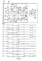
Figure 2 is a schematic and a torque flow diagram illustrating an exemplary embodiment of a transmission system, such as thetransmission system 110 ofFigure 1 . Thetransmission system 110 may include a twelve speed overdrive transmission with two reverse gear settings designated R1 and R2 and 12 forward gear settings designated 1st, 2nd, 3rd, .....,12th, which are typically referred to as R1 gear, R2 gear, 1st gear, ....12th gear, respectively. The transmission may include, but is not limited to, aninput shaft 201, amain shaft 205,counter shafts back box 225, and anoutput shaft 207. The transmission may include gear arrangements designated as KI, KII or 3, 2, 1, and R. - The gear arrangement Kl may include a
gear 251 that may be fixed on thecounter shaft 221, agear 255 that may be fixed on thecounter shaft 223, and agear 253 that may be operable to rotate around theinput shaft 201. The gear arrangement KII or 3 may include agear 261 that may be fixed on thecounter shaft 221, agear 265 that may be fixed on thecounter shaft 223, and agear 263 that may be operable to rotate around theinput shaft 201. Asynchronizer 231 may engage thegear 253 to rotate it about theinput shaft 201 and, therefore, rotategears synchronizer 231 may engage thegear 263 to rotate it about theinput shaft 201 and, therefore, rotategears - The
gear arrangement 2 may include agear 271 that may be fixed on thecounter shaft 221, agear 275 that may be fixed on thecounter shaft 223, and agear 273 that may be operable to rotate about themain shaft 205. Adog clutch 235 may engage thegear 263 allowing themain shaft 205 to rotate based on the gear arrangement KII or 3. Thedog clutch 235 may engage thegear 273 allowing themain shaft 205 to rotate based on thegear arrangement 2. - The
gear arrangement 1 may include, a gear 281 that may be fixed on thecounter shaft 221, agear 285 that may be fixed on thecounter shaft 223, and agear 283 that may be operable to rotate about themain shaft 205. The gear arrangement R may include agear 291 that may be fixed on thecounter shaft 221, agear 299 that may be fixed on thecounter shaft 223, idler gears 293 and 297 that may be operable to reverse the direction of rotation, and agear 295 that may be operable to rotate about themain shaft 205. Adog clutch 239 may engage thegear 283 allowing themain shaft 205 to rotate based on thegear arrangement 1. Thedog clutch 239 may engage thegear 295 allowing themain shaft 205 to rotate based on the gear arrangement R. - The
back box 225 may be a planetary back box that may include, but is not limited to, a sun gear, planetary gears (e.g., three planetary gears), and a synchronizer. Theoutput shaft 207 may be operatively coupled to theback box 225. Ayoke 209 may be attached to theoutput shaft 207, and theyoke 209 may connect with a drive line, drive shaft, or propeller shaft. - Based on the engagement of the various synchronizers and dog clutches, such as
synchronizer 231 anddog clutches Figure 2 ,1 st gear may occur when thesynchronizer 231 is engaged with thegear 263 and thedog clutch 239 is engaged with thegear 283. In this case, theinput shaft 201 may rotate thegear 263, which in turn rotates thecounter shafts gears gear 283 may rotate themain shaft 205 via thegears 281 and 285. Therefore, the torque or power may flow through theinput shaft 201 to thecounter shafts main shaft 205 via thegear arrangement 1, as shown by the power or torque pattern inFigure 2 . - Typically, the more individual gears that are engaged, the more heat the transmission generates. Therefore, when a component temperature of the
transmission system 110 and/or thenon-transmission system 114 reaches or rises above a predetermined threshold, the system for preventing damage to thevehicle 100 may shift to a gear setting that minimizes the number of engaged gears, such as direct gear. For example, as the vehicle is moving, thesensors processor 120 may send commands to the transmission system 110 (e.g., via a transmission controller) to shift to a direct gear to reduce heat generation. - Referring to
Figure 2 ,5 th and 11th gear are direct gears in afront box 227. Thesynchronizer 231 and thedog clutch 235 may simultaneously engagegear 263 directly connecting theinput shaft 201 and themain shaft 205. Therefore, the torque or power may flow directly through theinput shaft 201 and themain shaft 205. The torque flow to theoutput shaft 207 may depend on the engagement of gears within theback box 225. The 11th gear has direct torque or power flow from theinput shaft 201 to theoutput shaft 207, thus 11th gear may also be a direct gear in theback box 225. 5th gear shows a jog in the torque or power flow based on a gear arrangement within theback box 225. Therefore, theprocessor 120 may command thetransmission system 110 to shift to 11th gear at higher speeds to reduce heat generation and shift to 5th gear at lower speeds to reduce heat generation. Therefore, shifting to a direct gear reduces heat generated in the transmission. - Any type of transmission with any number of drive speeds may be used with the system for preventing damage to the
vehicle 100. Some or all of the gears of the transmission may continuously rotate even if they are not engaged. Also, the diameters of the gears may vary. - The diameter or size of the gears may also affect the generation of heat in the
transmission system 110. Thecounter shafts input shaft 201, themain shaft 205, and theoutput shaft 207, and their associated gears may also reach into the oil sump. As the gears turn, they may displace or churn a certain amount of oil, which generates heat. Therefore, when a component temperature of thetransmission system 110 and/or thenon-transmission system 114 reaches or rises above a predetermined threshold, the system for preventing damage to thevehicle 100 may shift to a gear arrangement having gears with smaller diameters to displace less oil and reduce heat generation. - For example, as the vehicle is moving, the
sensors processor 120 may send commands to the transmission system 110 (e.g., via a transmission controller) to shift to a gear or gear arrangement that utilizes gears with smaller diameters to displace less oil in the oil sump. The displacement of less oil generates less heat. However, the use of smaller diameter gears may generate more torque. Therefore, theprocessor 120 may be operable to weigh and calculate the benefits of heat reduction based on displacement of oil versus torque generated. The processor may send a command to thetransmission system 110 for choosing a gear set based on the calculated benefits. Alternatively, the processor may send a pattern of different commands to switch between gears sets, including a shift to a direct gear, based on the benefits of heat reduction at a given time. Also, the system for preventing damage to thevehicle 100 may shift to or prohibit a shift to any gear of thetransmission system 110 to reduce heat generation. Also, empirical data may be developed to define which gear arrangements generate the least amount of heat. This data may be used in the system for preventing damage to thevehicle 100 to shift to gear arrangements having the least amount of heat generation. -
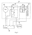
Figure 3 is a schematic diagram illustrating an exemplary embodiment of a cooling circuit, such as thecooling circuit 130 ofFigure 1 . Thecooling circuit 130 may include, but is not limited to, anoil pump 300, avariable flow bypass 304, apressure bypass 308, and aheat exchanger 320. Thecooling circuit 130 may be operable to cool or transfer heat away from the oil of the transmission and/or oil of non-transmission assemblies. - For example, the pump may take in oil from an
oil sump 330. Thepump 300 may output the oil to thevariable flow bypass 304. The oil may flow through apath 340 of thevariable flow bypass 304 to apressure bypass 308. Thepressure bypass 308 may be operable to protect theheat exchanger 320. For example, if the pressure of the oil is above a predetermined threshold or great enough to move apiston 323 that is supported by aspring 325, then the oil returns to theoil sump 330 without passing through theheat exchanger 320. This is to protect theheat exchanger 320 from excessive or high oil pressures that may physically damage theheat exchanger 320. If the pressure of the oil is below the predetermined threshold, then the oil passes through theheat exchanger 320, which cools the oil, and the oil returns to theoil sump 330. - The
variable flow bypass 304 may have three flow paths including, but not limited to, thepath 340, apath 344, and apath 348. As mentioned above, theflow path 340 may route the oil from thepump 300 to thepressure bypass 308. Thepath 344 may route a portion of the oil to thepressure bypass 308 and the other portion to theoil sump 330. Thepath 348 may route all of the oil back to theoil sump 330, bypassing both thepressure bypass 308 and theheat exchanger 320. - The
variable flow bypass 304 may be utilized for preventing damage to thevehicle 100. For example, thesensor 150 may continuously or periodically measure the level of oil or volumetric flow rate of oil in the transmission. Theprocessor 120 may analyze that data and determine if the oil level or volumetric flow rate is sufficient for operation of thevehicle 100. If the oil level or volumetric flow rate reaches or is below a predetermined threshold (e.g., there is an oil leak or not enough oil was deposited in the transmission), theprocessor 120 may send commands to theflow port controller 128 to select a flow path. Theprocessor 120 may determine that the oil level or volume is too low and command theflow port controller 128 to select thepath 348. In this case, all of the oil may bypass thepressure bypass 308 and theheat exchanger 320 to keep as much oil as possible in the transmission. Alternatively, if theprocessor 120 decides that the oil level is low but the oil is also at a certain temperature, theprocessor 120 may command thecontroller 128 to select thepath 344. In this case, a selected portion of the oil may bypass thepressure bypass 308 and theheat exchanger 320 to keep some oil in thetransmission system 110 and the other portion of oil may be sent to theheat exchanger 320 for cooling. Thepath 344 may be designed with two constant flow paths for the respective portions of oil or may have varying flow paths allowing for a precise selection of oil to be diverted to theheat exchanger 320 oroil sump 330. - Alternatively, the
cooling circuit 130 may prevent damage to thevehicle 100 by increasing oil flow rate to theheat exchanger 320. For example, thesensor 150 and/or 160 may continuously or periodically measure temperature of the transmission oil and/or non-transmission oil and send the temperature data to theprocessor 120. Theprocessor 120 may analyze the data and send commands to thepump 300 to increase the flow of oil when the oil temperature is too high or above a predetermined threshold. Alternatively, theprocessor 120 may send commands to theflow port controller 128 to increase the diameter of the paths of thevariable flow bypass 304 that direct the oil to theheat exchanger 320. - Also, in cold weather or climates, the oil may become highly viscous. The thick oil may cause performance problems as well as damage to the vehicle. Therefore, the
sensor 150 and/or 160 may monitor or measure the oil viscosity and/or temperature and send that data to theprocessor 120. Theprocessor 120 may analyze the data to determine if the oil temperature is too low or below a predetermined threshold and/or if the oil is too viscous, thick, or above a predetermined threshold. If the oil is too cold or viscous, theprocessor 120 may command theflow port controller 128 to select thepath heat exchanger 320 to heat the oil faster and avoid any damage to thevehicle 100. - The
flow port controller 128 is not limited to controlling thevariable flow bypass 304. Theflow port controller 128 may be operable to control and/or communicate with any other part of thecooling circuit 130. -
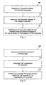
Figure 4 is a flowchart illustrating an example of a method for preventing damage to thevehicle 100. Inact 401, a parameter of a vehicle component may be measured or monitored. The vehicle component may be a transmission and/or non-transmission assembly. The transmission component may be oil of the transmission, and the non-transmission assembly component may be, for example, an exhaust pipe or exhaust. The parameter may be angular velocity of a shaft or gear, temperature of the transmission component or non-transmission assembly component, or volume, level, or volumetric flow rate of a component, such as transmission and/or non-transmission oil. Sensors that may be located at various positions in thevehicle 100, such as thesensors - In
act 411, the parameter of the vehicle component may be analyzed. A processor or a plurality of processors may analyze the measured data. The analysis may include, but is not limited to, determining if a parameter is above or below a predetermined threshold, interpolating and/or extrapolating stored data, comparing measured data with stored data, calculating a time period before damage occurs to a vehicle, such asvehicle 100, correlating oil temperature and oil volume or level, and determining oil life or wear based on the temperature of the oil. - In
act 421, a damage prevention process including reducing heat generation in the vehicle based on the analysis of the parameter may be performed. Reducing heat generation may include, but is not limited to, shifting to a direct gear, shifting to a gear that displaces or churns less oil, prohibiting or discontinuing EGR, redirecting or routing air to a non-transmission assembly or a transmission, and increasing flow rate in a cooler circuit. Other damage prevention processes may include warning a driver of oil life or wear, level of oil, and a time period before damage will occur to the vehicle, as well as, prohibiting ignition based on oil level or temperature of a transmission and/or non-transmission assembly component, and bypassing oil or a selected portion of oil away from a heat exchanger based on oil level or temperature. -
Figure 5 is a flowchart illustrating another example of a method for preventing damage to a vehicle. Inact 500, a parameter of oil of a vehicle transmission and/or a non-transmission assembly may be monitored or measured. The parameter may be oil temperature, level, volume, volumetric flow rate, or viscosity. Inact 510, the parameter of the oil of the vehicle transmission may be analyzed. The analysis includes, but is not limited to, determining a time period before damage to the vehicle based on the oil level or the volumetric flow rate of the oil, correlating oil temperature and the oil level of the volumetric flow rate of the oil, and other analyses discussed above. Inact 520, a damage prevention process may be performed based on the analysis of the oil. The damage prevention process may include, but is not limited to, warning a driver about the time period before damage to the vehicle, bypassing the oil or a selected amount of the oil away from a heat exchanger when the oil level or the volumetric flow rate of the oil is below a predetermined threshold, prohibiting ignition when the oil level is too low or if the oil temperature is too high, and any other damage preventing process related to transmission oil discussed above. - Referring to
Figure 1 , thememory 122 may include instructions for performing the steps of any of the methods, processes, calculations, or features described above. Thememory 122 may be a "computer-readable medium," "machine-readable medium," "propagated-signal" medium, and/or "signal-bearing medium" and may comprise any device that contains, stores, communicates, propagates, or transports software for use by or in connection with an instruction executable system, apparatus, or device. The machine-readable medium may selectively be, but not limited to, an electronic, magnetic, optical, electromagnetic, infrared, or semiconductor system, apparatus, device, or propagation medium. A non-exhaustive list of examples of a machine-readable medium would include: an electrical connection "electronic"' having one or more wires, a portable magnetic or optical disk, a volatile memory such as a Random Access Memory "RAM" (electronic), a Read-Only Memory "ROM" (electronic), an Erasable Programmable Read-Only Memory (EPROM or Flash memory) (electronic), or an optical fiber (optical). A machine-readable medium may also include a tangible medium upon which software is printed, as the software may be electronically stored as an image or in another format (e.g., through an optical scan), then complied, and/or interpreted or otherwise processed. The processed medium may then be stored in a computer and/or machine memory. - Although selected aspects, features, or components of the implementations are depicted as being stored in memories, all or part of the systems, including processes and/or instructions for performing processes, consistent with the system may be stored on, distributed across, or read from other machine-readable media, for example, secondary storage devices such as hard disks, floppy disks, and CD-ROMs; a signal received from a network; or other forms of ROM or RAM, some of which may be written to and read from in a vehicle, such as the
vehicle 100. - Any of the features, processes, or methods discussed above may be mixed and matched together to create a variety of damage preventing systems and/or methods for a vehicle, such as a truck. Also, the system for preventing damage to a vehicle described above may be in communication with a remote station or device via any variety of wireless networks and/or protocols. An operator at the remote station or operating the remote device may initiate any of the damage preventing processes discussed above.
- It is intended that the foregoing detailed description be regarded as illustrative rather than limiting, and that it be understood that the following claims, including all equivalents, are intended to define the scope of this invention. The claims may include the phrase "one of A and B" as an alternative expression that means one or more of A or one or more of B.
Claims (24)
- A system for preventing damage to a vehicle comprising:a first sensor operable to measure a first parameter relating to a transmission component in a vehicle and to provide a first parameter signal indicative of the measured first parameter; anda processor in communication with the first sensor and operable to receive the first parameter signal from the first sensor,wherein the processor is further operable to analyze the first parameter signal, andwherein the processor is further operable to initiate a damage prevention process including a reduction of heat generation in the vehicle based on the first parameter.
- The system of claim 1 further comprising:a baffle controller in communication with the processor; anda baffle operatively connected with the baffle controller,wherein the processor is operable to provide a baffle control signal to the baffle controller, andwherein the baffle controller is operable to control the baffle to route air flow to a transmission of the vehicle to reduce the heat generation.
- The system of claim 1 further comprising:a baffle controller in communication with the processor; anda baffle operatively connected with the baffle controller,wherein the processor is operable to provide a baffle control signal to the baffle controller, andwherein the baffle controller is operable to control the baffle to route air flow to a non-transmission assembly of the vehicle to reduce the heat generation.
- The system of claim 1 further comprising:a second sensor in communication with the processor and operable to measure a second parameter relating to a non-transmission assembly component in the vehicle and to provide a second parameter signal indicative of the second parameter,wherein the processor is further operable to receive the second parameter signal,wherein the processor is further operable to analyze the second parameter, andwherein the processor is further operable to initiate a damage prevention process including reducing heat generation in the vehicle based on the second parameter.
- The system of claim 4, wherein the non-transmission assembly component comprises an exhaust pipe, and the second parameter of the non-transmission assembly component comprises a temperature of the exhaust pipe.
- The system of claim 1, wherein the transmission component comprises oil, and the first parameter of the transmission component comprises at least one of a temperature of the oil and a volume of the oil.
- The system of claim 6, wherein the processor is further operable to correlate at least one of the temperature of the oil and the volume of the oil.
- The system of claim 1, wherein the processor is further operable to determine a time period before damage occurs to the vehicle, and the time period is incorporated with the damage prevention process.
- The system of claim 1, wherein the processor is further operable to initiate a shift to a direct gear as part of the damage prevention process.
- The system of claim 1, wherein the processor is further operable to initiate an increase of a flow rate in a cooler circuit as part of the damage prevention process.
- The system of claim 1, wherein the processor is further operable to initiate a prohibition of exhaust gas regeneration as part of the damage prevention process.
- The system of claim 1, wherein the processor is further operable to initiate a shift to a gear operable to displace less oil as part of the damage prevention process.
- A system for preventing damage to a vehicle comprising:a sensor operable to measure an oil parameter and to provide an oil parameter signal indicative of the oil parameter; anda processor in communication with the sensor that is operable to receive the oil parameter signal,wherein the processor is further operable to analyze the oil parameter signal, andwherein the processor is further operable to initiate a damage prevention process in a vehicle based on the oil parameter.
- The system of claim 13, wherein the oil parameter comprises at least one of an oil level of the oil and a volumetric flow rate of the oil.
- The system of claim 14, wherein the processor is further operable to determine a time period before damage occurs to the vehicle based on at least one of the oil level of the oil and the volumetric flow rate of the oil, and the time period is incorporated with the damage prevention process.
- The system of claim 15, wherein the processor is further operable to enable a warning indicator configured to warn a driver about the time period.
- The system of claim 14, wherein the processor is further operable to correlate a temperature of the oil and at least one of the oil level of the oil and the volumetric flow rate of the oil.
- The system of claim 13 further comprising:a flow port controller in communication with the processor;a variable flow bypass operatively connected with the flow port controller,wherein the processor is operable to provide a flow port control signal to the flow port controller, andwherein the flow port controller is operable to select a flow path of oil through the variable flow bypass.
- The system on claim 18, further comprising:a heat exchanger in fluid communication with the variable flow bypass; andan oil sump in fluid communication with the variable flow bypass;wherein the selected flow path is operable to direct the oil to the oil sump without passing through the heat exchanger.
- The system of claim 18, further comprising:a heat exchanger in fluid communication with the variable flow bypass; andan oil sump in fluid communication with the variable flow bypass;wherein the selected flow path includes a dual path that is operable to direct a first portion of the oil to the oil sump without passing through the heat exchanger and to direct a second portion of the oil through the heat exchanger.
- A system for preventing damage to a vehicle comprising:a sensor operable to measure a vehicle parameter and to provide a vehicle parameter signal indicative of the vehicle parameter;a processor in communication with the sensor that is operable to receive the vehicle parameter signal; anda starter interlock signal device in communication with the processor,wherein the starter interlock signal device is operable to receive a starter interlock control signal from the processor,wherein the starter interlock signal device is further operable to generate a starter interlock signal,wherein the processor is further operable to analyze the vehicle parameter signal, andwherein the processor is further operable to initiate a damage prevention process based on the vehicle parameter.
- The system of claim 21, wherein the vehicle parameter comprises at least one of an oil level of oil and a volumetric flow rate of oil, and wherein the processor is further operable to disable the starter interlock signal when at least one of the oil level of oil and the volumetric flow rate of the oil is below a predetermined threshold as part of the damage prevention process.
- The system of claim 21, wherein the vehicle parameter comprises a temperature of oil, and wherein the processor is further operable to disable the starter interlock signal when the temperature of the oil is above a predetermined threshold as part of the damage prevention process.
- The system of claim 21, wherein the vehicle parameter comprises a temperature of a non-transmission assembly component in the vehicle, and wherein the processor is further operable to disable the starter interlock signal when the temperature of the non-transmission assembly component is above a predetermined threshold as part of the damage prevention process.
Applications Claiming Priority (1)
| Application Number | Priority Date | Filing Date | Title |
|---|---|---|---|
| US11/809,969 US8392047B2 (en) | 2007-06-04 | 2007-06-04 | System for preventing damage to a vehicle |
Publications (3)
| Publication Number | Publication Date |
|---|---|
| EP2000706A2 true EP2000706A2 (en) | 2008-12-10 |
| EP2000706A3 EP2000706A3 (en) | 2011-10-12 |
| EP2000706B1 EP2000706B1 (en) | 2012-10-10 |
Family
ID=39760945
Family Applications (1)
| Application Number | Title | Priority Date | Filing Date |
|---|---|---|---|
| EP08156946A Expired - Fee Related EP2000706B1 (en) | 2007-06-04 | 2008-05-27 | System for preventing damage to a vehicle |
Country Status (2)
| Country | Link |
|---|---|
| US (1) | US8392047B2 (en) |
| EP (1) | EP2000706B1 (en) |
Cited By (1)
| Publication number | Priority date | Publication date | Assignee | Title |
|---|---|---|---|---|
| WO2019048947A1 (en) * | 2017-09-08 | 2019-03-14 | Alberto Escobar | Essential inspection system for machines |
Families Citing this family (9)
| Publication number | Priority date | Publication date | Assignee | Title |
|---|---|---|---|---|
| DE102009019814A1 (en) * | 2009-05-02 | 2010-11-04 | Bayerische Motoren Werke Aktiengesellschaft | Transmission e.g. automatic transmission, for use in vehicle, has bypass valve moved between opening and closing conditions, and hydraulic lines including transmission oil path that is released in opening condition and by-passes oil cooler |
| GB2471653A (en) * | 2009-06-30 | 2011-01-12 | Meritor Technology Inc | A method of controlling a fluid level around a transmission gear |
| US10598650B2 (en) * | 2012-08-22 | 2020-03-24 | General Electric Company | System and method for measuring an operative condition of a machine |
| US9784150B2 (en) * | 2013-10-28 | 2017-10-10 | Cummins Ip, Inc. | Lubricant level control for lubricated systems |
| DE102015204834A1 (en) * | 2015-03-18 | 2016-09-22 | Zf Friedrichshafen Ag | Oil supply arrangement and method for oil supply |
| DE102016215857A1 (en) * | 2016-08-24 | 2018-03-01 | Voith Patent Gmbh | Monitoring a hydrodynamic coupling |
| JP7463983B2 (en) * | 2021-02-18 | 2024-04-09 | トヨタ自動車株式会社 | Oil shortage detection system |
| US11821153B2 (en) | 2021-08-17 | 2023-11-21 | Caterpillar Paving Products Inc. | Milling machine with heat exchanger circuit |
| JP2025076019A (en) * | 2023-11-01 | 2025-05-15 | ナブテスコ株式会社 | Gearing |
Family Cites Families (52)
| Publication number | Priority date | Publication date | Assignee | Title |
|---|---|---|---|---|
| US4684917A (en) * | 1986-05-16 | 1987-08-04 | Briggs & Stratton Corporation | Low oil warning circuit |
| JPH07103930B2 (en) * | 1987-12-28 | 1995-11-08 | アイシン・エィ・ダブリュ株式会社 | Fail-safe control device for electronically controlled automatic transmission |
| US4947331A (en) * | 1988-07-25 | 1990-08-07 | Eaton Corporation | Upshift logic |
| US4995357A (en) * | 1989-11-13 | 1991-02-26 | Briggs & Stratton Corporation | Engine shut-off circuit |
| US5521581A (en) * | 1993-08-05 | 1996-05-28 | Proulx; Raymond A. | Fluid level and temperature monitor and alarm system for an automobile cooling system |
| JP3455369B2 (en) * | 1996-06-26 | 2003-10-14 | 日立建機株式会社 | Front control device for construction machinery |
| WO1998001739A2 (en) * | 1996-06-27 | 1998-01-15 | Control Devices, Inc. | In situ oil quality evaluation with an acoustic sensor |
| US5803863A (en) * | 1997-03-03 | 1998-09-08 | Caterpillar Inc. | Transmission warm-up control strategy |
| DE19709445B4 (en) | 1997-03-07 | 2004-01-15 | Volkswagen Ag | Device and method for calculating and displaying service intervals |
| DE19906558B4 (en) * | 1999-02-10 | 2004-04-15 | Zf Friedrichshafen Ag | Hydraulic system for pressurizing a variator of an automatic transmission with an emergency drive device |
| US6176796B1 (en) * | 1999-03-26 | 2001-01-23 | Polaris Industries Inc. | Continuously variable transmission with clutch having enhanced air cooling |
| US6208245B1 (en) * | 1999-08-02 | 2001-03-27 | Curtis Instruments, Inc. | Engine oil change indicator system |
| DE19943004B4 (en) * | 1999-09-09 | 2004-11-18 | Dr.Ing.H.C. F. Porsche Ag | Cooling device for an internal combustion engine |
| US6327900B1 (en) * | 1999-12-20 | 2001-12-11 | General Motors Corporation | Oil life monitor for diesel engines |
| GB2369656A (en) * | 2000-11-21 | 2002-06-05 | Luk Lamellen & Kupplungsbau | Automatic transmission hydraulic actuation system having an isolating valve which prevent leaks |
| JP3521873B2 (en) * | 2001-01-17 | 2004-04-26 | トヨタ自動車株式会社 | Hydraulic control device for automatic transmission for vehicles |
| JP3875506B2 (en) * | 2001-04-03 | 2007-01-31 | 三菱電機株式会社 | Overheat protection device and method for automobile starter |
| US6810850B2 (en) * | 2001-04-20 | 2004-11-02 | Jenara Enterprises Ltd. | Apparatus and control for variable exhaust brake |
| DE10129072A1 (en) | 2001-06-15 | 2002-12-19 | Bosch Gmbh Robert | Monitoring process and device for determining condition of lubricating oil in automatic transmission uses measurements of temperature pattern trend |
| US6650977B2 (en) * | 2001-08-01 | 2003-11-18 | International Truck Intellectual Property Company, Llc | Automated vehicle inspection system |
| JP4010127B2 (en) * | 2001-09-14 | 2007-11-21 | スズキ株式会社 | Transmission mechanism cooling structure |
| JP3915966B2 (en) * | 2001-10-15 | 2007-05-16 | 日本サーモスタット株式会社 | Control method of electronic control thermostat |
| DE10157714A1 (en) * | 2001-11-24 | 2003-06-26 | Daimler Chrysler Ag | Method and devices for carrying out the method for influencing the operating temperature of a hydraulic operating means for a drive unit of a vehicle |
| DE60325436D1 (en) * | 2002-03-27 | 2009-02-05 | Calsonic Kansei Corp | Cooling device of a water-cooled Brennkraftmascine and transmission oil cooler module |
| JP3851203B2 (en) * | 2002-03-28 | 2006-11-29 | トヨタ自動車株式会社 | Shift control device and shift control method for automatic transmission |
| US6851328B2 (en) * | 2002-04-18 | 2005-02-08 | Kubota Corporation | Control apparatus for transmission |
| JP3839368B2 (en) * | 2002-06-28 | 2006-11-01 | アイシン・エィ・ダブリュ株式会社 | Hydraulic control device for automatic transmission |
| US20040045749A1 (en) * | 2002-09-06 | 2004-03-11 | Ford Global Technologies, Inc. | Cooling system and method for a hybrid electric vehicle |
| US7182048B2 (en) * | 2002-10-02 | 2007-02-27 | Denso Corporation | Internal combustion engine cooling system |
| US6883394B2 (en) * | 2002-10-15 | 2005-04-26 | Borgwarner, Inc. | Method for controlling the positioning of the synchronizers of a dual clutch transmission |
| US6715597B1 (en) * | 2002-10-25 | 2004-04-06 | Borgwarner, Inc. | Dual clutch transmission clutch cooling control method |
| JP4002860B2 (en) * | 2003-06-12 | 2007-11-07 | ヤンマー株式会社 | Fuel injection control device for fuel injection pump |
| US7349794B2 (en) * | 2003-09-03 | 2008-03-25 | Malone Specialty, Inc. | Engine protection system |
| US7184878B2 (en) * | 2003-09-03 | 2007-02-27 | Malone Specialty, Inc. | Engine protection system |
| JP4096863B2 (en) * | 2003-11-07 | 2008-06-04 | トヨタ自動車株式会社 | Engine starting device and engine starting method |
| US8041779B2 (en) * | 2003-12-15 | 2011-10-18 | Honda Motor Co., Ltd. | Method and system for facilitating the exchange of information between a vehicle and a remote location |
| US6920412B1 (en) * | 2004-01-26 | 2005-07-19 | General Motors Corporation | Real time life models for automatic transmission fluids |
| US7449994B1 (en) * | 2004-02-06 | 2008-11-11 | Brp Us Inc. | Engine mounted fault indicators |
| US6959239B2 (en) * | 2004-02-25 | 2005-10-25 | General Motors Corporation | Transmission and torque converter cooling control |
| US7002267B2 (en) * | 2004-03-22 | 2006-02-21 | General Motors Corporation | Method and apparatus for cooling a hybrid transmission electric motor |
| FR2871205B1 (en) * | 2004-06-03 | 2007-10-05 | Peugeot Citroen Automobiles Sa | WHEEL CLUTCH TRANSMISSION ELEMENT FOR AUTOMOTIVE VEHICLE TRACTION CHAIN, AND MOTOR VEHICLE EQUIPPED WITH SUCH ELEMENT |
| EP1619422B1 (en) * | 2004-07-09 | 2007-05-09 | C.R.F. Società Consortile per Azioni | A servo-assisted control system for the gears of a double clutch gearbox of a motor vehicle |
| WO2006065833A2 (en) * | 2004-12-13 | 2006-06-22 | Gomery Victor E | Low oil level indicator |
| US7937198B2 (en) * | 2004-12-29 | 2011-05-03 | Snap-On Incorporated | Vehicle or engine diagnostic systems supporting fast boot and reprogramming |
| EP1686291A2 (en) * | 2005-01-31 | 2006-08-02 | Hitachi, Ltd. | Control method and device for a gear transmission |
| US7223205B2 (en) * | 2005-02-17 | 2007-05-29 | General Motors Corporation | Method for controlling engine and/or transmission temperature |
| JP4539470B2 (en) * | 2005-07-12 | 2010-09-08 | スズキ株式会社 | Engine intake system |
| JP4934327B2 (en) * | 2006-02-09 | 2012-05-16 | 本田技研工業株式会社 | General-purpose engine oil level drop judgment device |
| US7478572B2 (en) * | 2006-02-27 | 2009-01-20 | Gm Global Technology Operations, Inc. | Transmission with torque sensors and method of controlling a transmission |
| JP2007232047A (en) * | 2006-02-28 | 2007-09-13 | Hitachi Ltd | Control apparatus and control method for automobile |
| US7426433B1 (en) * | 2006-11-02 | 2008-09-16 | Cold Fusion Nitrous Systems, Lp | Method and switch for controlling exhaust gas temperature |
| US7702447B2 (en) * | 2006-12-18 | 2010-04-20 | United Technologies Corporation | Method and system for identifying gas turbine engine faults |
-
2007
- 2007-06-04 US US11/809,969 patent/US8392047B2/en not_active Expired - Fee Related
-
2008
- 2008-05-27 EP EP08156946A patent/EP2000706B1/en not_active Expired - Fee Related
Cited By (1)
| Publication number | Priority date | Publication date | Assignee | Title |
|---|---|---|---|---|
| WO2019048947A1 (en) * | 2017-09-08 | 2019-03-14 | Alberto Escobar | Essential inspection system for machines |
Also Published As
| Publication number | Publication date |
|---|---|
| US20080300746A1 (en) | 2008-12-04 |
| EP2000706A3 (en) | 2011-10-12 |
| EP2000706B1 (en) | 2012-10-10 |
| US8392047B2 (en) | 2013-03-05 |
Similar Documents
| Publication | Publication Date | Title |
|---|---|---|
| EP2000706B1 (en) | System for preventing damage to a vehicle | |
| US8050814B2 (en) | Apparatus and method for determining remaining transmission oil life | |
| CN115743160B (en) | Methods and systems for estimating the wear of drive belts in continuously variable transmissions (CVTs). | |
| US8343010B2 (en) | Shift to direct drive during coast conditions | |
| CN103089988B (en) | Method for diagnosing fail of oil temperature sensor for an automatic transmission | |
| US20080194383A1 (en) | Method for Adapting an Automated Mechanical Transmission Based on a Measured Pto Load | |
| EP2125420B1 (en) | A method for adapting vehicle drivetrain control based on a measured pto load | |
| CN103913256B (en) | The diagnostic device of temperature sensor | |
| US9726129B2 (en) | Method for determining a fuel fraction in oil | |
| JP3194094B2 (en) | Method and apparatus for measuring temperature / viscosity of lubricating oil for transmission | |
| JP2010065637A (en) | Method and device for diagnosing degradation of lubricating oil in industrial vehicle | |
| CN114110042B (en) | A temperature control method for a dual clutch transmission | |
| CN108331915A (en) | A kind of passenger-cargo carriage automatic gear box control method and system | |
| CN102080717B (en) | Thermal protection control method for automatic transmission box or stepless transmission box | |
| US20170089456A1 (en) | Selectively controllable filtration system of a transmission and method thereof | |
| CN105270388B (en) | For controlling the method and system of hybrid electric vehicle | |
| EP3008362B1 (en) | Vehicle transmission and a method for operating a vehicle transmission | |
| CN113442850A (en) | Vehicle management system | |
| CN111731317A (en) | Fluid system for a vehicle and diagnostic method for said system | |
| JP2020067391A (en) | Abnormality diagnosis device | |
| KR20040034268A (en) | Method of diagnosing fail of oil temperature sensor for an automatic transmission in vehicles | |
| CN101965446B (en) | Power Source Braking System to Prevent Engine Stall | |
| KR101273668B1 (en) | Method for detecting panel error of cluster for vehicle | |
| EP3768995B1 (en) | Method for thermal protection of an automated gearbox of a motor vehicle | |
| US6715344B2 (en) | Process for determining the current state of a lubricant |
Legal Events
| Date | Code | Title | Description |
|---|---|---|---|
| PUAI | Public reference made under article 153(3) epc to a published international application that has entered the european phase |
Free format text: ORIGINAL CODE: 0009012 |
|
| AK | Designated contracting states |
Kind code of ref document: A2 Designated state(s): AT BE BG CH CY CZ DE DK EE ES FI FR GB GR HR HU IE IS IT LI LT LU LV MC MT NL NO PL PT RO SE SI SK TR |
|
| AX | Request for extension of the european patent |
Extension state: AL BA MK RS |
|
| PUAL | Search report despatched |
Free format text: ORIGINAL CODE: 0009013 |
|
| AK | Designated contracting states |
Kind code of ref document: A3 Designated state(s): AT BE BG CH CY CZ DE DK EE ES FI FR GB GR HR HU IE IS IT LI LT LU LV MC MT NL NO PL PT RO SE SI SK TR |
|
| AX | Request for extension of the european patent |
Extension state: AL BA MK RS |
|
| RIC1 | Information provided on ipc code assigned before grant |
Ipc: B60R 16/023 20060101ALI20110906BHEP Ipc: G07C 5/00 20060101ALI20110906BHEP Ipc: F16H 57/04 20100101ALI20110906BHEP Ipc: F16H 61/12 20100101AFI20110906BHEP |
|
| 17P | Request for examination filed |
Effective date: 20120412 |
|
| GRAP | Despatch of communication of intention to grant a patent |
Free format text: ORIGINAL CODE: EPIDOSNIGR1 |
|
| AKX | Designation fees paid |
Designated state(s): DE SE |
|
| GRAS | Grant fee paid |
Free format text: ORIGINAL CODE: EPIDOSNIGR3 |
|
| GRAA | (expected) grant |
Free format text: ORIGINAL CODE: 0009210 |
|
| AK | Designated contracting states |
Kind code of ref document: B1 Designated state(s): DE SE |
|
| REG | Reference to a national code |
Ref country code: DE Ref legal event code: R096 Ref document number: 602008019243 Country of ref document: DE Effective date: 20121206 |
|
| REG | Reference to a national code |
Ref country code: SE Ref legal event code: TRGR |
|
| PGFP | Annual fee paid to national office [announced via postgrant information from national office to epo] |
Ref country code: SE Payment date: 20130513 Year of fee payment: 6 Ref country code: DE Payment date: 20130522 Year of fee payment: 6 |
|
| PLBE | No opposition filed within time limit |
Free format text: ORIGINAL CODE: 0009261 |
|
| STAA | Information on the status of an ep patent application or granted ep patent |
Free format text: STATUS: NO OPPOSITION FILED WITHIN TIME LIMIT |
|
| 26N | No opposition filed |
Effective date: 20130711 |
|
| REG | Reference to a national code |
Ref country code: DE Ref legal event code: R097 Ref document number: 602008019243 Country of ref document: DE Effective date: 20130711 |
|
| REG | Reference to a national code |
Ref country code: DE Ref legal event code: R119 Ref document number: 602008019243 Country of ref document: DE |
|
| PG25 | Lapsed in a contracting state [announced via postgrant information from national office to epo] |
Ref country code: SE Free format text: LAPSE BECAUSE OF NON-PAYMENT OF DUE FEES Effective date: 20140528 |
|
| REG | Reference to a national code |
Ref country code: SE Ref legal event code: EUG |
|
| REG | Reference to a national code |
Ref country code: DE Ref legal event code: R119 Ref document number: 602008019243 Country of ref document: DE Effective date: 20141202 |
|
| PG25 | Lapsed in a contracting state [announced via postgrant information from national office to epo] |
Ref country code: DE Free format text: LAPSE BECAUSE OF NON-PAYMENT OF DUE FEES Effective date: 20141202 |