EP2000644A2 - Variabler Ventilatorantrieb - Google Patents
Variabler Ventilatorantrieb Download PDFInfo
- Publication number
- EP2000644A2 EP2000644A2 EP08156535A EP08156535A EP2000644A2 EP 2000644 A2 EP2000644 A2 EP 2000644A2 EP 08156535 A EP08156535 A EP 08156535A EP 08156535 A EP08156535 A EP 08156535A EP 2000644 A2 EP2000644 A2 EP 2000644A2
- Authority
- EP
- European Patent Office
- Prior art keywords
- shaft
- sheave
- axially
- driver
- variable
- Prior art date
- Legal status (The legal status is an assumption and is not a legal conclusion. Google has not performed a legal analysis and makes no representation as to the accuracy of the status listed.)
- Withdrawn
Links
- 238000002485 combustion reaction Methods 0.000 claims abstract description 7
- 239000012530 fluid Substances 0.000 claims description 6
- 230000008878 coupling Effects 0.000 claims 3
- 238000010168 coupling process Methods 0.000 claims 3
- 238000005859 coupling reaction Methods 0.000 claims 3
- 239000010705 motor oil Substances 0.000 description 4
- 230000004048 modification Effects 0.000 description 2
- 238000012986 modification Methods 0.000 description 2
- 125000006850 spacer group Chemical group 0.000 description 2
- 238000001816 cooling Methods 0.000 description 1
- 238000005461 lubrication Methods 0.000 description 1
- 230000002093 peripheral effect Effects 0.000 description 1
Images

Classifications
-
- F—MECHANICAL ENGINEERING; LIGHTING; HEATING; WEAPONS; BLASTING
- F01—MACHINES OR ENGINES IN GENERAL; ENGINE PLANTS IN GENERAL; STEAM ENGINES
- F01P—COOLING OF MACHINES OR ENGINES IN GENERAL; COOLING OF INTERNAL-COMBUSTION ENGINES
- F01P5/00—Pumping cooling-air or liquid coolants
- F01P5/02—Pumping cooling-air; Arrangements of cooling-air pumps, e.g. fans or blowers
- F01P5/04—Pump-driving arrangements
-
- F—MECHANICAL ENGINEERING; LIGHTING; HEATING; WEAPONS; BLASTING
- F01—MACHINES OR ENGINES IN GENERAL; ENGINE PLANTS IN GENERAL; STEAM ENGINES
- F01P—COOLING OF MACHINES OR ENGINES IN GENERAL; COOLING OF INTERNAL-COMBUSTION ENGINES
- F01P7/00—Controlling of coolant flow
- F01P7/02—Controlling of coolant flow the coolant being cooling-air
- F01P7/04—Controlling of coolant flow the coolant being cooling-air by varying pump speed, e.g. by changing pump-drive gear ratio
- F01P7/046—Controlling of coolant flow the coolant being cooling-air by varying pump speed, e.g. by changing pump-drive gear ratio using mechanical drives
Definitions
- the present invention relates to a variable speed fan drive.
- variable speed fan drive systems used in work vehicles such as agricultural tractors typically use a viscous drive on the system cooling fan.
- a hydraulically operated variable speed fan drive is described in US Patent No. 7,165,514 , issued in January 2007 and assigned to the assignee of this application.
- This variable speed fan drive has a driven sheave and fan which are mounted on an auxiliary shaft on the engine.
- This variable speed fan drive has a driver sheave unit with a non-rotating axially movable piston operated by pressurized engine oil controlled by a solenoid operated valve.
- a rotating driver shaft extends through the piston and is non-rotatably connected to an axially fixed driver sheave and an axially movable driver sheave.
- a further need is to provide such a variable speed fan drive system which is operated by high pressure hydraulic system fluid.
- a further need is to provide such a variable speed fan drive system wherein the driving sheave unit is a stand-alone unit which can be pressure tested apart from an engine.
- variable speed fan drive for a vehicle powered by an internal combustion engine.
- the fan drive may have a driver variable sheave unit, a driven variable sheave unit and a belt engaging both the driver and driven variable sheave units.
- the driver variable sheave unit includes a driver shaft drivingly coupled to an engine output shaft, a first axially fixed half sheave mounted for rotation with the driver shaft, and a first axially movable half sheave member mounted for rotation with the driver shaft and movable axially on the driver shaft.
- the first axially movable half sheave member includes a belt engaging flange formed integrally with an axially movable piston member mounted for rotation with the driver shaft and movable axially in response to hydraulic pressure.
- the driven variable sheave unit may comprise a driven shaft having an end rotatably supported by bearings in a housing, a second axially fixed half sheave fixed to the driven shaft for rotation therewith, an second axially movable half sheave mounted on the driven shaft for rotation therewith, a spring retainer mounted on the driven shaft for rotation therewith, and a plurality of return springs mounted between the retainer and the second axially movable half sheave.
- the return springs are spaced apart from each other and spaced apart from an exterior surface of the driven shaft.
- the second axially movable half sheave is located between the second axially fixed half sheave and the return springs.
- the driven shaft has a member formed thereon which engages the spring retainer and holds the spring retainer on the driven shaft against a bias of the return springs.
- the spring retainer has spaced apart tabs which projecting therefrom, and a magnetic sensor is mounted on the housing for generating a speed signal as the tabs move past the sensor.
- variable speed fan drive for a vehicle powered by an internal combustion engine may have a driving variable sheave assembly, a driven variable sheave assembly and a belt engaging both the driving variable sheave assembly and the driven variable sheave assembly, wherein the driving variable sheave assembly being driven by an engine output shaft, the driving variable sheave assembly having a first axially fixed half sheave and a first axially movable half sheave movable axially in response to hydraulic pressure; the driven variable sheave assembly drivingly coupled to a fan, the driven variable sheave assembly comprising a shaft having an end rotatably supported by bearings in a housing, a second axially fixed half sheave fixed to the shaft for rotation therewith, an second axially movable half sheave mounted on the shaft for rotation therewith, a spring retainer mounted on the shaft for rotation therewith, and a plurality of return springs mounted between the retainer and the second axially movable half sheave, the return springs being
- variable speed fan drive for a vehicle powered by an internal combustion engine may comprise a driver shaft coupled for rotation with an output shaft of the engine; a first axially fixed half sheave coupled for rotation with the driver shaft; a first axially movable half sheave mounted on the driver shaft for rotation with the driver shaft, the driver shaft and the first axially movable half sheave forming a pressure chamber, and the first axially movable half sheave being movable axially in response to hydraulic pressure in said chamber; a driven shaft supported for rotation on a housing of the engine; a second axially fixed half sheave fixed to the driven shaft for rotation therewith; a second axially movable half sheave mounted on the driven shaft for rotation therewith; a spring retainer mounted on the shaft for rotation therewith; a plurality of return springs mounted between the retainer and the second axially movable half sheave, the return springs being spaced apart from each other and spaced apart from an exterior surface of the shaft,
- the driven shaft may include a first fustroconical surface formed thereon; and the spring retainer may include a hollow hub including a second fustroconical surface formed thereon, the first fustroconical surface engaging the second frustroconical surface to hold the spring retainer on the shaft and to center the spring retainer thereon.
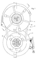
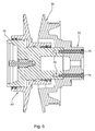
- a variable speed fan drive system 10 includes a driver sheave unit 12 and a driven sheave unit 14.
- a fan spacer 15 is fixed to the outer end of driven sheave unit 14.
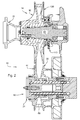
- a rotatable engine crankshaft 16 projects from a vehicle engine (not shown) and carries a crankshaft seal and damper hub 18 which is surrounded by a crankshaft seal package 20.
- a torsional damper 22 is bolted to the hub 18.
- a driver shaft 24 is bolted by a plurality of crankshaft screws 26 to an end of the crankshaft 16.
- Driver shaft 24 includes an axially outer larger diameter part 21, and an axially inner smaller diameter part 23.
- Driver shaft 24 also includes a plurality of bolt bores 25 which extend therethrough and which receive the screws 26.
- a central stepped bore 27 extends axially into the outer end of the shaft 24.
- a rotating axially fixed driver half sheave 30 is mounted for rotation with the driver shaft 24 and includes a central hub 32 held between the damper 22 and an inner end of the shaft 24.
- Driver half sheave 30 also includes an angled belt flange 34 which projects outwardly from the hub 32.
- the bolt bores 25 and screws 26 also extend through hub 32.
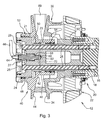
- a rotating axially movable driver half sheave 40 is mounted for rotation with the driver shaft 24 and is axially movable with respect to the driver shaft 24.
- Movable driver half sheave 40 includes a hollow hub 42 and an angled belt flange 44 which projects outwardly from the hub 42.
- Hub 42 includes a larger diameter part 46 and a smaller diameter part 48.
- Hub parts 46 and 48 are slidable on driver shaft parts 23 and 21, respectively.
- Driver half sheave 40 and driver shaft 24 enclose a pressure chamber 50 which is sealed by seals 52 carried in grooves in hub part 48 and by seals 54 carried in grooves in hub part 46.
- Axially extending keys 56 are received by corresponding grooves 58 on an inner surface of hub part 46. As a result of the cooperation of the keys 56 and grooves 58, the half sheave 40 rotates with the driver shaft 24, but is axially slidable with respect to driver shaft 24.
- a non-rotating union member 60 is received in the bore 27 of the rotating driver shaft 24 and encloses a chamber 62.
- An end 64 of a hydraulic line 66 is sealingly connected to the outer end of union member 60.
- a passage 68 extends through union member 60 and communicates pressurized hydraulic fluid from line 66 to chamber 62.
- Radial passages 70 in the driver shaft 24 communicates pressurized hydraulic fluid from chamber 62 to chamber 50.
- a belt 69 is received between and is driven by half sheave flanges 34 and 44.
- the driver shaft 24 includes an axially extending blind bore 71 which is aligned with bore 72 in the hub 32 of the driver half sheave 30.
- a dowel pin 74 is received in bores 71 and 72 so that driver half sheave 30 is coupled for rotation shaft 24 and driver half sheave 40.
- the driver half sheave 30 is coupled to the driver shaft 24 by a pair of bolts 75 which are screwed into threaded bores 76 which extend into the inner end of shaft 24.
- the driver sheave unit 12 is a stand-alone or self-contained unit which can be pressure tested apart from an engine.
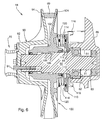
- the driven sheave unit 14 includes a driven shaft 80 with a mounting stub shaft 81 received and supported for rotation by bearings 82 and 83 which are mounted in a bore 84 in a part of the engine cover 86.
- An outwardly facing frustoconical shoulder surface 85 is formed on shaft 80 adjacent to stub 81.
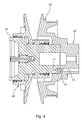
- a rotating axially fixed driven half sheave 90 is mounted for rotation with the driven shaft 80 and includes a central hub 92 which is attached to the end of shaft 80 by bolts 91.
- Driven half sheave 90 also includes an angled belt flange 94 which projects outwardly from the hub 92.
- a fan spacer 15 is bolted to the end of hub 92.
- a rotating axially movable driven half sheave 100 is mounted for rotation with the driven shaft 80 and is axially movable with respect to the driven shaft 80.
- Driven half sheave 100 includes a hollow hub 102 and an angled belt flange 104 which projects outwardly from the hub 102.
- Axially extending keys 106 are formed on the shaft 80 and are received by corresponding grooves 108 on an inner surface of hub 102.
- the half sheave 100 rotates with the driven shaft 80, but is axially slidable with respect to driven shaft 80.
- Belt 69 is engaged by flanges 94 and 104.
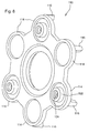
- a hollow annular spring retainer 110 is mounted on the shaft 80, and has annular hub 111 with an inner frustoconical surface 112 which engages the shoulder surface 85 and which operates to center the spring retainer 110 on the shaft 80.
- Retainer 110 includes a plurality (such as six) of spring holding cups 114 spaced apart and positioned radially outwardly from the hub 111. Each cup 114 holds an end of a return spring 120. The other end of each return spring 120 engages movable driven half sheave 100, and is biased to urge driven half sheave 100 towards fixed half sheave 94.
- a plurality of legs or tabs 116 extend axially away from an outer peripheral edge of each cup 114.
- three or half of the cups 114 have central hollow projections 122 through which extend stepped bores 124. Screw threads are formed on the smaller diameter portion of each bore 124. Each bore 124 threadably receives a spring retainer screw 126. Each spring retainer screw 126 extends through a bore 128 in the half sheave 100, through a corresponding one of the springs 120 and into a corresponding one of bores 124. Screws 126 have heads 127 which are engagable with the half sheave 100, and thus hold the half sheave 100, spring retainer 110 and springs 120 together as a sub-assembly.
- a speed sensor 130 is mounted in a bore in an arm 132 which projects from the engine cover 86, and is held in a position close to an outer edge of a circular path through which the legs 116 rotate.
- the sensor 130 generates signals as the legs 116 move past, and is preferably a commercially available variable reluctance type sensor.
Landscapes
- Engineering & Computer Science (AREA)
- Chemical & Material Sciences (AREA)
- Combustion & Propulsion (AREA)
- Mechanical Engineering (AREA)
- General Engineering & Computer Science (AREA)
- Transmissions By Endless Flexible Members (AREA)
- Structures Of Non-Positive Displacement Pumps (AREA)
Applications Claiming Priority (1)
| Application Number | Priority Date | Filing Date | Title |
|---|---|---|---|
| US11/757,455 US20080295786A1 (en) | 2007-06-04 | 2007-06-04 | Variable speed fan drive |
Publications (2)
| Publication Number | Publication Date |
|---|---|
| EP2000644A2 true EP2000644A2 (de) | 2008-12-10 |
| EP2000644A3 EP2000644A3 (de) | 2012-09-12 |
Family
ID=39773203
Family Applications (1)
| Application Number | Title | Priority Date | Filing Date |
|---|---|---|---|
| EP08156535A Withdrawn EP2000644A3 (de) | 2007-06-04 | 2008-05-20 | Variabler Ventilatorantrieb |
Country Status (2)
| Country | Link |
|---|---|
| US (1) | US20080295786A1 (de) |
| EP (1) | EP2000644A3 (de) |
Families Citing this family (2)
| Publication number | Priority date | Publication date | Assignee | Title |
|---|---|---|---|---|
| US11377998B1 (en) * | 2020-12-15 | 2022-07-05 | Caterpillar Inc. | Fan adapter for an engine |
| US11473488B2 (en) * | 2020-12-15 | 2022-10-18 | Caterpillar Inc. | Engine fan adapter systems and methods |
Citations (1)
| Publication number | Priority date | Publication date | Assignee | Title |
|---|---|---|---|---|
| US7165514B2 (en) | 2004-10-06 | 2007-01-23 | Deere & Company | Variable speed fan drive |
Family Cites Families (13)
| Publication number | Priority date | Publication date | Assignee | Title |
|---|---|---|---|---|
| US2709374A (en) * | 1952-09-10 | 1955-05-31 | American Pulley Co | Adjustable diameter sheaves |
| US2709373A (en) * | 1952-09-10 | 1955-05-31 | American Pulley Co | Adjustable diameter sheaves |
| US2917937A (en) * | 1958-07-21 | 1959-12-22 | Adiel Y Dodge | Variable speed drive |
| FR1442281A (fr) * | 1964-08-26 | 1966-06-17 | Cazeneuve Sa | Perfectionnements aux variateurs de vitesse à courroie trapézoïdale, à commande par liquide sous pression |
| DE1909887A1 (de) * | 1969-02-27 | 1970-09-17 | Germann Helmut | Lagerung von Kegelscheiben in stufenlos einstellbaren Getrieben |
| US3736804A (en) * | 1971-03-26 | 1973-06-05 | Lovejoy Inc | Pulley assembly |
| US3872842A (en) * | 1973-06-14 | 1975-03-25 | Kress Corp | Speed control system for fan in engine cooling system |
| US4541821A (en) * | 1982-11-27 | 1985-09-17 | Aisin-Warner Limited | V-belt type stepless transmission |
| JPS62233415A (ja) * | 1986-04-04 | 1987-10-13 | Komatsu Ltd | ラジエ−タフアンの回転速度制御法 |
| US4899861A (en) * | 1987-03-16 | 1990-02-13 | Rockford Powertrain, Inc. | Variable speed drive for engine cooling fans |
| US5527225A (en) * | 1992-12-29 | 1996-06-18 | Dana Corporation | Full time four-wheel drive system |
| US5580324A (en) * | 1995-06-05 | 1996-12-03 | Powerbloc Ibc Canada Inc. | Driven pulley with a clutch |
| DE10132976A1 (de) * | 2001-07-06 | 2003-01-23 | Zf Batavia Llc | Einrichtung zur Führung einer beweglichen Kegelscheibe eines CVT-Variators |
-
2007
- 2007-06-04 US US11/757,455 patent/US20080295786A1/en not_active Abandoned
-
2008
- 2008-05-20 EP EP08156535A patent/EP2000644A3/de not_active Withdrawn
Patent Citations (1)
| Publication number | Priority date | Publication date | Assignee | Title |
|---|---|---|---|---|
| US7165514B2 (en) | 2004-10-06 | 2007-01-23 | Deere & Company | Variable speed fan drive |
Also Published As
| Publication number | Publication date |
|---|---|
| US20080295786A1 (en) | 2008-12-04 |
| EP2000644A3 (de) | 2012-09-12 |
Similar Documents
| Publication | Publication Date | Title |
|---|---|---|
| USRE41285E1 (en) | Planetary transmission apparatus including vehicle-wheel hub | |
| US4811614A (en) | Power take-off drive unit | |
| US9045040B2 (en) | PTO drivelines | |
| JP3097439B2 (ja) | 無段変速機の油路構造 | |
| CA1207618A (en) | Clutch drive | |
| US5199317A (en) | Forward and reverse power shift transmission | |
| US20040045784A1 (en) | Hydraulically operated clutch system | |
| KR19990028898A (ko) | 두 회전축 사이의 토크 전달 장치 | |
| US20140102228A1 (en) | PTO Drivelines | |
| US5014655A (en) | Camshaft drive of a multi-cylinder V-engine | |
| US9434250B2 (en) | Modular power take-off assembly | |
| US9297426B2 (en) | Power take-off with remotely mounted clutch assembly and lubricated spline | |
| CA1207617A (en) | Clutch drive with antirotation spring | |
| US20070267265A1 (en) | Clutch arrangement | |
| RU2715252C1 (ru) | Коробка отбора мощности и ее детали | |
| EP2000644A2 (de) | Variabler Ventilatorantrieb | |
| AU2006335265B2 (en) | Brake apparatus and method | |
| US5391122A (en) | Hydromechanical drive system | |
| SK329192A3 (en) | Motor with internal combustion and with pump located on camshaft | |
| US4633986A (en) | Clutch/brake apparatus | |
| US6874610B2 (en) | Compact dry power takeoff unit | |
| US10704663B2 (en) | Modular disconnecting drive module with torque vectoring augmentation | |
| US9482290B2 (en) | Transmission gear engagement mechanism and method of operation | |
| US6000518A (en) | Clutch transmitting rotating motion | |
| JP2689594B2 (ja) | 遊星歯車装置 |
Legal Events
| Date | Code | Title | Description |
|---|---|---|---|
| PUAI | Public reference made under article 153(3) epc to a published international application that has entered the european phase |
Free format text: ORIGINAL CODE: 0009012 |
|
| AK | Designated contracting states |
Kind code of ref document: A2 Designated state(s): AT BE BG CH CY CZ DE DK EE ES FI FR GB GR HR HU IE IS IT LI LT LU LV MC MT NL NO PL PT RO SE SI SK TR |
|
| AX | Request for extension of the european patent |
Extension state: AL BA MK RS |
|
| RIC1 | Information provided on ipc code assigned before grant |
Ipc: F01P 7/04 20060101ALI20120403BHEP Ipc: F01P 5/04 20060101AFI20120403BHEP |
|
| PUAL | Search report despatched |
Free format text: ORIGINAL CODE: 0009013 |
|
| AK | Designated contracting states |
Kind code of ref document: A3 Designated state(s): AT BE BG CH CY CZ DE DK EE ES FI FR GB GR HR HU IE IS IT LI LT LU LV MC MT NL NO PL PT RO SE SI SK TR |
|
| AX | Request for extension of the european patent |
Extension state: AL BA MK RS |
|
| RIC1 | Information provided on ipc code assigned before grant |
Ipc: F01P 7/04 20060101ALI20120809BHEP Ipc: F01P 5/04 20060101AFI20120809BHEP |
|
| AKY | No designation fees paid | ||
| REG | Reference to a national code |
Ref country code: DE Ref legal event code: R108 |
|
| REG | Reference to a national code |
Ref country code: DE Ref legal event code: R108 Effective date: 20130515 |
|
| STAA | Information on the status of an ep patent application or granted ep patent |
Free format text: STATUS: THE APPLICATION IS DEEMED TO BE WITHDRAWN |
|
| 18D | Application deemed to be withdrawn |
Effective date: 20130313 |