EP2000364A1 - A dashboard assembly for a motor vehicule provided with a connector for connecting a portable electronic device - Google Patents
A dashboard assembly for a motor vehicule provided with a connector for connecting a portable electronic device Download PDFInfo
- Publication number
- EP2000364A1 EP2000364A1 EP07425506A EP07425506A EP2000364A1 EP 2000364 A1 EP2000364 A1 EP 2000364A1 EP 07425506 A EP07425506 A EP 07425506A EP 07425506 A EP07425506 A EP 07425506A EP 2000364 A1 EP2000364 A1 EP 2000364A1
- Authority
- EP
- European Patent Office
- Prior art keywords
- dashboard
- seat
- connector
- dashboard assembly
- assembly according
- Prior art date
- Legal status (The legal status is an assumption and is not a legal conclusion. Google has not performed a legal analysis and makes no representation as to the accuracy of the status listed.)
- Granted
Links
Images


Classifications
-
- B—PERFORMING OPERATIONS; TRANSPORTING
- B60—VEHICLES IN GENERAL
- B60R—VEHICLES, VEHICLE FITTINGS, OR VEHICLE PARTS, NOT OTHERWISE PROVIDED FOR
- B60R11/00—Arrangements for holding or mounting articles, not otherwise provided for
- B60R11/02—Arrangements for holding or mounting articles, not otherwise provided for for radio sets, television sets, telephones, or the like; Arrangement of controls thereof
- B60R11/0258—Arrangements for holding or mounting articles, not otherwise provided for for radio sets, television sets, telephones, or the like; Arrangement of controls thereof for navigation systems
-
- B—PERFORMING OPERATIONS; TRANSPORTING
- B60—VEHICLES IN GENERAL
- B60R—VEHICLES, VEHICLE FITTINGS, OR VEHICLE PARTS, NOT OTHERWISE PROVIDED FOR
- B60R11/00—Arrangements for holding or mounting articles, not otherwise provided for
- B60R11/02—Arrangements for holding or mounting articles, not otherwise provided for for radio sets, television sets, telephones, or the like; Arrangement of controls thereof
- B60R11/0241—Arrangements for holding or mounting articles, not otherwise provided for for radio sets, television sets, telephones, or the like; Arrangement of controls thereof for telephones
-
- B—PERFORMING OPERATIONS; TRANSPORTING
- B60—VEHICLES IN GENERAL
- B60R—VEHICLES, VEHICLE FITTINGS, OR VEHICLE PARTS, NOT OTHERWISE PROVIDED FOR
- B60R11/00—Arrangements for holding or mounting articles, not otherwise provided for
- B60R11/02—Arrangements for holding or mounting articles, not otherwise provided for for radio sets, television sets, telephones, or the like; Arrangement of controls thereof
- B60R11/0252—Arrangements for holding or mounting articles, not otherwise provided for for radio sets, television sets, telephones, or the like; Arrangement of controls thereof for personal computers, e.g. laptops, notebooks
-
- H—ELECTRICITY
- H01—ELECTRIC ELEMENTS
- H01R—ELECTRICALLY-CONDUCTIVE CONNECTIONS; STRUCTURAL ASSOCIATIONS OF A PLURALITY OF MUTUALLY-INSULATED ELECTRICAL CONNECTING ELEMENTS; COUPLING DEVICES; CURRENT COLLECTORS
- H01R13/00—Details of coupling devices of the kinds covered by groups H01R12/70 or H01R24/00 - H01R33/00
- H01R13/44—Means for preventing access to live contacts
- H01R13/447—Shutter or cover plate
- H01R13/453—Shutter or cover plate opened by engagement of counterpart
- H01R13/4536—Inwardly pivoting shutter
-
- H—ELECTRICITY
- H01—ELECTRIC ELEMENTS
- H01R—ELECTRICALLY-CONDUCTIVE CONNECTIONS; STRUCTURAL ASSOCIATIONS OF A PLURALITY OF MUTUALLY-INSULATED ELECTRICAL CONNECTING ELEMENTS; COUPLING DEVICES; CURRENT COLLECTORS
- H01R13/00—Details of coupling devices of the kinds covered by groups H01R12/70 or H01R24/00 - H01R33/00
- H01R13/66—Structural association with built-in electrical component
- H01R13/717—Structural association with built-in electrical component with built-in light source
- H01R13/7175—Light emitting diodes (LEDs)
-
- H—ELECTRICITY
- H01—ELECTRIC ELEMENTS
- H01R—ELECTRICALLY-CONDUCTIVE CONNECTIONS; STRUCTURAL ASSOCIATIONS OF A PLURALITY OF MUTUALLY-INSULATED ELECTRICAL CONNECTING ELEMENTS; COUPLING DEVICES; CURRENT COLLECTORS
- H01R13/00—Details of coupling devices of the kinds covered by groups H01R12/70 or H01R24/00 - H01R33/00
- H01R13/73—Means for mounting coupling parts to apparatus or structures, e.g. to a wall
- H01R13/74—Means for mounting coupling parts in openings of a panel
- H01R13/741—Means for mounting coupling parts in openings of a panel using snap fastening means
-
- B—PERFORMING OPERATIONS; TRANSPORTING
- B60—VEHICLES IN GENERAL
- B60R—VEHICLES, VEHICLE FITTINGS, OR VEHICLE PARTS, NOT OTHERWISE PROVIDED FOR
- B60R11/00—Arrangements for holding or mounting articles, not otherwise provided for
- B60R2011/0001—Arrangements for holding or mounting articles, not otherwise provided for characterised by position
- B60R2011/0003—Arrangements for holding or mounting articles, not otherwise provided for characterised by position inside the vehicle
- B60R2011/0005—Dashboard
-
- B—PERFORMING OPERATIONS; TRANSPORTING
- B60—VEHICLES IN GENERAL
- B60R—VEHICLES, VEHICLE FITTINGS, OR VEHICLE PARTS, NOT OTHERWISE PROVIDED FOR
- B60R11/00—Arrangements for holding or mounting articles, not otherwise provided for
- B60R2011/0042—Arrangements for holding or mounting articles, not otherwise provided for characterised by mounting means
- B60R2011/0049—Arrangements for holding or mounting articles, not otherwise provided for characterised by mounting means for non integrated articles
- B60R2011/005—Connection with the vehicle part
- B60R2011/0059—Connection with the vehicle part using clips, clamps, straps or the like
-
- B—PERFORMING OPERATIONS; TRANSPORTING
- B60—VEHICLES IN GENERAL
- B60R—VEHICLES, VEHICLE FITTINGS, OR VEHICLE PARTS, NOT OTHERWISE PROVIDED FOR
- B60R11/00—Arrangements for holding or mounting articles, not otherwise provided for
- B60R2011/0042—Arrangements for holding or mounting articles, not otherwise provided for characterised by mounting means
- B60R2011/0049—Arrangements for holding or mounting articles, not otherwise provided for characterised by mounting means for non integrated articles
- B60R2011/0064—Connection with the article
- B60R2011/0075—Connection with the article using a containment or docking space
-
- H—ELECTRICITY
- H01—ELECTRIC ELEMENTS
- H01R—ELECTRICALLY-CONDUCTIVE CONNECTIONS; STRUCTURAL ASSOCIATIONS OF A PLURALITY OF MUTUALLY-INSULATED ELECTRICAL CONNECTING ELEMENTS; COUPLING DEVICES; CURRENT COLLECTORS
- H01R13/00—Details of coupling devices of the kinds covered by groups H01R12/70 or H01R24/00 - H01R33/00
- H01R13/62—Means for facilitating engagement or disengagement of coupling parts or for holding them in engagement
- H01R13/627—Snap or like fastening
- H01R13/6275—Latching arms not integral with the housing
-
- H—ELECTRICITY
- H01—ELECTRIC ELEMENTS
- H01R—ELECTRICALLY-CONDUCTIVE CONNECTIONS; STRUCTURAL ASSOCIATIONS OF A PLURALITY OF MUTUALLY-INSULATED ELECTRICAL CONNECTING ELEMENTS; COUPLING DEVICES; CURRENT COLLECTORS
- H01R2201/00—Connectors or connections adapted for particular applications
- H01R2201/26—Connectors or connections adapted for particular applications for vehicles
Definitions
- the present invention relates to a dashboard assembly for a motor vehicle provided with a connector for connecting a portable electronic device, in particular a palm-top device or a satellite navigator.
- Palm-top devices and portable satellite navigators are relatively widespread, and the need is felt to use them in motor vehicles in a convenient and relatively simple way.
- a support which, in turn, is fixed to the dashboard or to the windscreen of the motor vehicle, for example, via suction pads.
- the electronic device must then be connected via cables to a 12-V electrical-supply connector commonly provided in the passenger compartment.
- connectors are known generally referred to as "cigarette-lighter sockets", or else connectors of the type described in the German patent application No. DE19849800A1 .
- the aim of the present invention is to provide a dashboard assembly for a motor vehicle equipped with a connector for connecting a portable electronic device that will enable a simple and inexpensive solution of the problems set forth above.
- a dashboard assembly for a motor vehicle comprising:
- said seat houses six electrical contacts, four of which for data signals, and two, one for a 12-V supply and the other for connection to ground.
- the reference number 1 designates, as a whole, a dashboard assembly (partially illustrated) of a motor vehicle.
- the dashboard assembly 1 delimits at the front the passenger compartment of the motor vehicle and comprises a dashboard 2, which is defined by a wall with an external face 3 facing upwards and has a through opening 4 ( Figure 3 ) .
- the dashboard assembly 1 then comprises a connector 5, which extends through the opening 4 along a vertical or inclined axis 6 and comprises an internal seat 7.
- the seat 7 is defined by an end wall 8, by a side wall 9 with substantially rectangular annular rim, and by a hatch 10, opposite to the wall 8.
- the hatch 10 can be moved for inserting an end 12 of a support 14 into the seat 7 ( Figure 2 ): in particular, the hatch 10 is guided by the wall 9 for translating into the seat 7 against the action of a spring 15 (partially illustrated with a dashed line) set between the wall 8 and the hatch 10, from a raised position, in which it closes an inlet 16 of the seat 7 and is set axially bearing upon an internal edge (not illustrated) of the wall 9, to a lowered position (represented with a dashed line), in which the inlet 16 is open and is engaged by the end 12.
- a spring 15 partially illustrated with a dashed line
- the end wall 8 defines a piece that is separate from the wall 9 and that is coupled by snap action, in a way not illustrated, to the wall 9 itself, after the hatch 10 and the spring 15 have been inserted into the seat 7 from the bottom towards the inlet 16.
- the wall 9 terminates with an annular projection 18, which projects radially towards the outside with respect to the axis 6 and is rested axially against the edge of the opening 4.
- the projection 18 and the hatch 10 set in a closed position are substantially parallel to the external face 3 of the dashboard 2.
- a reinforcement ring 19 is coupled in a fixed position to the internal face of the dashboard 2, for example, via hot bonding between the plastic materials of the ring 19 and the dashboard 2.
- the ring 19 has an internal profile that corresponds to that of the opening 4 and comprises a reference portion (not illustrated), which enables proper orientation of the ring 19 during coupling on the internal face of the dashboard 2.
- the connector 5 is coupled by snap action and clamped with respect to the dashboard 2 via elements 20 that project towards the outside from respective side faces 21 of the wall 9; for example, the connector 5 is coupled via springs (not illustrated) carried by the connector 5 or else via elastic teeth made of a single piece with the wall 9: the ring 19 and the edge of the opening 4 are set axially between the projection 18 and the elements 20.
- the elements 20 undergo elastic deformation radially inwards, snap outwards when the connector 5 reaches the end-of-travel position (i.e., when the projection 18 comes to bear upon the face 3), and come to co-operate axially bearing upon the ring 19 on the opposite side of the dashboard 2 for withholding the connector 5.
- fixing could be obtained via screws (not illustrated), screwed through the projection 18 and the dashboard 2 and having their own heads hidden then by an annular cap (not illustrated), coupled by snap action to the projection 18.
- the wall 9 has at least one retention hole 22 provided for withholding the end 12 engaging in the seat 7, as will be described more fully in what follows.
- the wall 9 comprises two faces 23 set between the faces 21: one of the faces 23 carries, in fixed positions, six electrical contacts 24 (illustrated schematically), which are parallel to the axis 6 and define the terminals of respective electrical connections insulated from one another. Said electrical connections terminate, underneath the wall 8, with respective contacts 26, which, together with the bottom end of the connector 5, define an electrical attachment or socket 28, which can be connected to the electrical system of the motor vehicle via wiring (not illustrated).
- the contacts 24 are associated, respectively, to an electrical supply with a 12-V voltage (which is commonly available on motor vehicles), to an electrical ground signal, and to four electrical data-transfer signals. These four electrical data-transfer signals are in analog format (audio and video) or else digital format (for example in the format envisaged by the USB standard). Obviously, for motor vehicles having an electrical system with a 24-V voltage, instead of a 12-V voltage, also the electrical-supply signal of the connector 5 could be a 24-V signal.
- the wiring that connects the connector 5 to the electrical system of the motor vehicle supplies, in a way not illustrated, also a LED 30 (schematically illustrated), which is carried by an electrical circuit set on the wall 8 in the seat 7 for back-lighting the hatch 10, which, in turn, has an area 31 permeable to light ( Figure 1 ), defining a logo or else a wording that comes to be visible in the passenger compartment in an extremely defined way thanks to the light transmitted and coming from the LED 30.
- the ring 19 forms part of a reinforcement system provided around at least part of the connector 5 for resisting vibrations and forces exerted, in use, by the support 14 on the connector 5, for example, the weight and inertial forces due to accelerations or decelerations of the motor vehicle.
- the reinforcement system could comprise reinforcement ribbings and/or areas with increased thickness on the connector 5 and/or on the dashboard 2.
- the contacts 24 could be arranged on the wall 8, or else at the bottom of the seat 7, and/or the hatch 10 could be hinged to the wall 9 around an axis 33, for turning from the raised position towards one of the faces 23 against the action of a spring (not illustrated) when it is pushed from the end 12 during coupling of the support 14 to the connector 5.
- the support 14 comprises a body 35 or supporting arm, which extends in cantilever fashion and vertically with respect to the dashboard 2 when the end 12 engages the seat 7.
- a head 36 is coupled to the body 35 via an articulated joint 37 and is configured so as to be coupled in a releasable way to a portable electronic device (not illustrated) having a display of its own, for example, to a satellite navigator or else a palm-top.
- the head 36 comprises both a mechanical-attachment device for fixing of the portable electronic device, and a plurality of electrical contacts 38 for transfer of the signals and of the electrical supply between the portable electronic device and the motor vehicle.
- the contacts 38 constitute the terminals of respective electrical connections that extend through the articulated joint 37 and the body 35 and terminate with respective contacts (not visible in the attached figures), which are carried by the end 12 and are coupled to the contacts 24 when the end 12 engages the seat 7.
- the end 12 carries two engagement teeth 41, which are opposed and engage respective holes 22 when the seat 7 is engaged by the end 12.
- the teeth 41 are releasable by pressing manually two pushbuttons 43 arranged along the sides of the body 35: in particular, when the pushbuttons 43 are pressed against the elastic action of retention exerted by a spring (not illustrated), the teeth 41 recede within the end 12 so as to be able to make the end 12 to slide along the axis 6 towards the outside of the seat 7.
- the hatch 10 opens automatically under the thrust exerted downwards of the support 14.
- the teeth 41 reenter automatically within the end 12 when they encounter the projection 18 in so far as they have respective profiles 44 inclined and convergent with respect to one another downwards. Once the teeth 41 reach the position of the holes 22, they automatically snap laterally outwards into the holes 22 to withhold the end 12 engaged in the seat 7.
- the position of the display of the portable electronic device is stable, irrespective of the vibrations present during travel of the motor vehicle thanks to the stiffness provided by the reinforcement system and by the arm 35.
- the arm 35 then guarantees a convenient and clear vision of the display of the portable electronic device.
- the reinforcement system could be different from what is described by way of example, and/or the shape of the connector 5 could be different from the one illustrated.
- the portable electronic device can be connected to the electrical system of the motor vehicle so as to interact with the electronic control unit of the motor vehicle for an exchange of information and/or so as to use other devices or systems installed on the motor vehicle, for example, the loudspeakers and/or the antenna.
Abstract
Description
- The present invention relates to a dashboard assembly for a motor vehicle provided with a connector for connecting a portable electronic device, in particular a palm-top device or a satellite navigator.
- Palm-top devices and portable satellite navigators are relatively widespread, and the need is felt to use them in motor vehicles in a convenient and relatively simple way. In the passenger compartment of motor vehicles, it is known to engage the portable electronic device to a support, which, in turn, is fixed to the dashboard or to the windscreen of the motor vehicle, for example, via suction pads. The electronic device must then be connected via cables to a 12-V electrical-supply connector commonly provided in the passenger compartment. For example, for electrical supply, connectors are known generally referred to as "cigarette-lighter sockets", or else connectors of the type described in the German patent application No.
DE19849800A1 . - The known solutions just described are far from satisfactory, in so far as the operations of connection and disconnection on the motor vehicle of the portable electronic device are relatively inconvenient and require time and attention. In addition, the cables for connection to the electrical-supply connector are relatively cumbersome.
- The aim of the present invention is to provide a dashboard assembly for a motor vehicle equipped with a connector for connecting a portable electronic device that will enable a simple and inexpensive solution of the problems set forth above.
- Provided according to the present invention is a dashboard assembly for a motor vehicle comprising:
- a dashboard having a through opening; and
- a connector engaging said opening and defining a seat, which houses a contact for 12-V or 24-V electrical supply and is accessible by opening a hatch;
- retention means for withholding a support of said portable electronic device engaging in said seat; and
- reinforcement means, arranged around at least part of said seat.
- Preferably, said seat houses six electrical contacts, four of which for data signals, and two, one for a 12-V supply and the other for connection to ground.
- The invention will now be described with reference to the annexed plates of drawings, which illustrate a non-limiting example of embodiment thereof and in which:
-
Figure 1 is a partial illustration of a preferred embodiment of the dashboard assembly for a motor vehicle provided with a connector for connecting a portable electronic device, according to the present invention; -
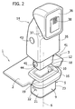
Figure 2 is similar toFigure 1 and illustrates, at a reduced scale, the dashboard assembly and a support to be coupled to the connector ofFigure 1 ; -
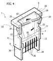
Figure 3 is a schematic cutaway view, at an enlarged scale, of the connector; and -
Figure 4 is similar toFigure 3 and illustrates a variant of the connector. - In
Figures 1 to 3 , thereference number 1 designates, as a whole, a dashboard assembly (partially illustrated) of a motor vehicle. Thedashboard assembly 1 delimits at the front the passenger compartment of the motor vehicle and comprises adashboard 2, which is defined by a wall with anexternal face 3 facing upwards and has a through opening 4 (Figure 3 ) . Thedashboard assembly 1 then comprises aconnector 5, which extends through theopening 4 along a vertical orinclined axis 6 and comprises aninternal seat 7. Theseat 7 is defined by anend wall 8, by aside wall 9 with substantially rectangular annular rim, and by ahatch 10, opposite to thewall 8. Thehatch 10 can be moved for inserting anend 12 of asupport 14 into the seat 7 (Figure 2 ): in particular, thehatch 10 is guided by thewall 9 for translating into theseat 7 against the action of a spring 15 (partially illustrated with a dashed line) set between thewall 8 and thehatch 10, from a raised position, in which it closes aninlet 16 of theseat 7 and is set axially bearing upon an internal edge (not illustrated) of thewall 9, to a lowered position (represented with a dashed line), in which theinlet 16 is open and is engaged by theend 12. - In order to install the
hatch 10 in theseat 7 against the aforesaid internal edge, theend wall 8 defines a piece that is separate from thewall 9 and that is coupled by snap action, in a way not illustrated, to thewall 9 itself, after thehatch 10 and thespring 15 have been inserted into theseat 7 from the bottom towards theinlet 16. - In a position corresponding to the
inlet 16, thewall 9 terminates with anannular projection 18, which projects radially towards the outside with respect to theaxis 6 and is rested axially against the edge of theopening 4. In practice, theprojection 18 and thehatch 10 set in a closed position are substantially parallel to theexternal face 3 of thedashboard 2. - A
reinforcement ring 19 is coupled in a fixed position to the internal face of thedashboard 2, for example, via hot bonding between the plastic materials of thering 19 and thedashboard 2. Thering 19 has an internal profile that corresponds to that of theopening 4 and comprises a reference portion (not illustrated), which enables proper orientation of thering 19 during coupling on the internal face of thedashboard 2. - With reference to what is schematically illustrated in
Figure 3 , theconnector 5 is coupled by snap action and clamped with respect to thedashboard 2 viaelements 20 that project towards the outside fromrespective side faces 21 of thewall 9; for example, theconnector 5 is coupled via springs (not illustrated) carried by theconnector 5 or else via elastic teeth made of a single piece with the wall 9: thering 19 and the edge of theopening 4 are set axially between theprojection 18 and theelements 20. When theconnector 5 is inserted axially through theopening 4 in the assembly step, theelements 20 undergo elastic deformation radially inwards, snap outwards when theconnector 5 reaches the end-of-travel position (i.e., when theprojection 18 comes to bear upon the face 3), and come to co-operate axially bearing upon thering 19 on the opposite side of thedashboard 2 for withholding theconnector 5. As an alternative to theelements 20, fixing could be obtained via screws (not illustrated), screwed through theprojection 18 and thedashboard 2 and having their own heads hidden then by an annular cap (not illustrated), coupled by snap action to theprojection 18. - The
wall 9 has at least oneretention hole 22 provided for withholding theend 12 engaging in theseat 7, as will be described more fully in what follows. Thewall 9 comprises twofaces 23 set between the faces 21: one of thefaces 23 carries, in fixed positions, six electrical contacts 24 (illustrated schematically), which are parallel to theaxis 6 and define the terminals of respective electrical connections insulated from one another. Said electrical connections terminate, underneath thewall 8, withrespective contacts 26, which, together with the bottom end of theconnector 5, define an electrical attachment orsocket 28, which can be connected to the electrical system of the motor vehicle via wiring (not illustrated). - The
contacts 24 are associated, respectively, to an electrical supply with a 12-V voltage (which is commonly available on motor vehicles), to an electrical ground signal, and to four electrical data-transfer signals. These four electrical data-transfer signals are in analog format (audio and video) or else digital format (for example in the format envisaged by the USB standard). Obviously, for motor vehicles having an electrical system with a 24-V voltage, instead of a 12-V voltage, also the electrical-supply signal of theconnector 5 could be a 24-V signal. - The wiring that connects the
connector 5 to the electrical system of the motor vehicle supplies, in a way not illustrated, also a LED 30 (schematically illustrated), which is carried by an electrical circuit set on thewall 8 in theseat 7 for back-lighting thehatch 10, which, in turn, has anarea 31 permeable to light (Figure 1 ), defining a logo or else a wording that comes to be visible in the passenger compartment in an extremely defined way thanks to the light transmitted and coming from theLED 30. - The
ring 19 forms part of a reinforcement system provided around at least part of theconnector 5 for resisting vibrations and forces exerted, in use, by thesupport 14 on theconnector 5, for example, the weight and inertial forces due to accelerations or decelerations of the motor vehicle. As an alternative to or in combination with thering 19, the reinforcement system could comprise reinforcement ribbings and/or areas with increased thickness on theconnector 5 and/or on thedashboard 2. - According to variant embodiments schematically illustrated in
Figure 4 , thecontacts 24 could be arranged on thewall 8, or else at the bottom of theseat 7, and/or thehatch 10 could be hinged to thewall 9 around anaxis 33, for turning from the raised position towards one of thefaces 23 against the action of a spring (not illustrated) when it is pushed from theend 12 during coupling of thesupport 14 to theconnector 5. - According to what is shown in
Figure 2 , thesupport 14 comprises abody 35 or supporting arm, which extends in cantilever fashion and vertically with respect to thedashboard 2 when theend 12 engages theseat 7. Ahead 36 is coupled to thebody 35 via an articulatedjoint 37 and is configured so as to be coupled in a releasable way to a portable electronic device (not illustrated) having a display of its own, for example, to a satellite navigator or else a palm-top. Thehead 36 comprises both a mechanical-attachment device for fixing of the portable electronic device, and a plurality ofelectrical contacts 38 for transfer of the signals and of the electrical supply between the portable electronic device and the motor vehicle. - The
contacts 38 constitute the terminals of respective electrical connections that extend through the articulatedjoint 37 and thebody 35 and terminate with respective contacts (not visible in the attached figures), which are carried by theend 12 and are coupled to thecontacts 24 when theend 12 engages theseat 7. - Preferably, the
end 12 carries twoengagement teeth 41, which are opposed and engagerespective holes 22 when theseat 7 is engaged by theend 12. Theteeth 41 are releasable by pressing manually twopushbuttons 43 arranged along the sides of the body 35: in particular, when thepushbuttons 43 are pressed against the elastic action of retention exerted by a spring (not illustrated), theteeth 41 recede within theend 12 so as to be able to make theend 12 to slide along theaxis 6 towards the outside of theseat 7. - Instead, during insertion of the
end 12 through theinlet 16, thehatch 10 opens automatically under the thrust exerted downwards of thesupport 14. In addition, theteeth 41 reenter automatically within theend 12 when they encounter theprojection 18 in so far as they haverespective profiles 44 inclined and convergent with respect to one another downwards. Once theteeth 41 reach the position of theholes 22, they automatically snap laterally outwards into theholes 22 to withhold theend 12 engaged in theseat 7. - From the foregoing description, it emerges clearly how the operations of coupling and uncoupling of the portable electronic device in the passenger compartment of the motor vehicle are extremely simple, and how it is possible to guarantee a complete communication for electrical supply and for data signals between the motor vehicle and said portable electronic device without the use of additional cables arranged in the passenger compartment.
- It is moreover evident how the position of the display of the portable electronic device is stable, irrespective of the vibrations present during travel of the motor vehicle thanks to the stiffness provided by the reinforcement system and by the
arm 35. Thearm 35 then guarantees a convenient and clear vision of the display of the portable electronic device. - Finally, from the foregoing description, it emerges clearly that modifications and variations can be made to the
dashboard assembly 1 described without thereby departing from the sphere of protection of the present invention. - In particular, the reinforcement system could be different from what is described by way of example, and/or the shape of the
connector 5 could be different from the one illustrated. In addition, the portable electronic device can be connected to the electrical system of the motor vehicle so as to interact with the electronic control unit of the motor vehicle for an exchange of information and/or so as to use other devices or systems installed on the motor vehicle, for example, the loudspeakers and/or the antenna.
Claims (10)
- A dashboard assembly (1) for a motor vehicle comprising:- a dashboard (2) having a through opening (4); and- a connector (5) engaging said opening (4) and defining a seat (7), which houses a contact for 12-V or 24-V electrical supply and is accessible by opening a hatch (10);said dashboard assembly being characterized in that said seat (7) houses at least one electrical contact for transmission of data, and in that it comprises:- retention means (22) for withholding a support (14) of said portable electronic device engaging in said seat (7); and- reinforcement means (19) arranged around at least part of said seat (7).
- The dashboard assembly according to Claim 1, characterized in that said seat (7) houses six electrical contacts, four of which for data signals, and two of which, one for a 12-V supply and one for connection to ground.
- The dashboard assembly according to Claim 1 or Claim 2, characterized in that said retention means comprise at least one retention opening (22) provided on a side face of said seat (7).
- The dashboard assembly according to any one of the preceding claims, characterized in that said reinforcement means (19) are fixed with respect to said dashboard (2).
- The dashboard assembly according to Claim 4, characterized in that said reinforcement means comprise a reinforcement ring (19) around said connector (5).
- The dashboard assembly according to Claim 5, characterized in that said reinforcement ring (19) constitutes an element distinct from said dashboard (2) and fixed to the internal face of said dashboard (2).
- The dashboard assembly according to Claim 5 or Claim 6, characterized in that said connector (5) is coupled by snap action to said reinforcement ring (19).
- The dashboard assembly according to any one of the preceding claims, characterized in that said contacts are arranged on a side face (23) of said seat (7).
- The dashboard assembly according to any one of the preceding claims, characterized in that said hatch (10) can be moved by means of rotation towards a side face (23) of said seat (7).
- The dashboard assembly according to any one of the preceding claims, characterized in that it comprises a LED (30) set in said seat (7) for back-lighting said hatch (10), and in that said hatch (10) has an area permeable to light.
Applications Claiming Priority (1)
| Application Number | Priority Date | Filing Date | Title |
|---|---|---|---|
| IT000408A ITTO20070408A1 (en) | 2007-06-08 | 2007-06-08 | DASHBOARD UNIT OF A MOTOR VEHICLE EQUIPPED WITH A CONNECTOR TO CONNECT A PORTABLE ELECTRONIC DEVICE |
Publications (3)
| Publication Number | Publication Date |
|---|---|
| EP2000364A1 true EP2000364A1 (en) | 2008-12-10 |
| EP2000364A8 EP2000364A8 (en) | 2009-06-17 |
| EP2000364B1 EP2000364B1 (en) | 2010-05-12 |
Family
ID=39301148
Family Applications (1)
| Application Number | Title | Priority Date | Filing Date |
|---|---|---|---|
| EP07425506A Active EP2000364B1 (en) | 2007-06-08 | 2007-08-03 | A dashboard assembly for a motor vehicle provided with a connector for connecting a portable electronic device |
Country Status (5)
| Country | Link |
|---|---|
| EP (1) | EP2000364B1 (en) |
| AT (1) | ATE467528T1 (en) |
| DE (1) | DE602007006454D1 (en) |
| ES (1) | ES2345460T3 (en) |
| IT (1) | ITTO20070408A1 (en) |
Cited By (7)
| Publication number | Priority date | Publication date | Assignee | Title |
|---|---|---|---|---|
| WO2010110854A1 (en) * | 2009-03-23 | 2010-09-30 | Tyco Electronics Corporation | Connector assembly with a light indicative of a connector status |
| DE102011082355B3 (en) * | 2011-09-08 | 2012-11-29 | Faurecia Innenraum Systeme Gmbh | Power socket for motor vehicle has slats and cover connected with one another by closing system such that movement of cover from closing position to opening position is permitted only when slats are moved in predefined position |
| ITTO20130470A1 (en) * | 2013-06-06 | 2014-12-07 | Fiat Group Automobiles Spa | VEHICLE DASHBOARD PROVIDED WITH A HOUSING TO SUPPORT A PORTABLE ELECTRONIC DEVICE |
| WO2017220413A1 (en) * | 2016-06-22 | 2017-12-28 | Bury Sp. Z. O. O | Holding system for an electronic device in a vehicle |
| FR3085137A1 (en) * | 2018-08-23 | 2020-02-28 | Psa Automobiles Sa | ATTACHMENT OF MULITMEDIA DEVICE IN A VEHICLE |
| DE102022118165A1 (en) | 2022-07-20 | 2024-01-25 | Faurecia Innenraum Systeme Gmbh | Vehicle interior restraint system |
| EP4321386A1 (en) * | 2022-08-10 | 2024-02-14 | Xiaomi EV Technology Co., Ltd. | Holder coupling assembly and insertable holder |
Citations (6)
| Publication number | Priority date | Publication date | Assignee | Title |
|---|---|---|---|---|
| FR2010008A1 (en) * | 1968-06-01 | 1970-02-13 | Schoeller Et Co | |
| DE19849800A1 (en) | 1998-10-29 | 2000-05-04 | Volkswagen Ag | Electrical socket for motor vehicle dashboard has self-closing cover or shutter over open end of receptacle |
| EP1334877A1 (en) * | 2002-02-06 | 2003-08-13 | Renault s.a.s. | Telephone connection kit in a vehicle |
| EP1544955A2 (en) * | 2002-03-20 | 2005-06-22 | ERICH JAEGER GmbH & Co. KG | Socket for electrical connectors |
| DE102004035871A1 (en) | 2004-07-23 | 2006-02-16 | Volkswagen Ag | Multifunctional plug-in system |
| WO2006063137A1 (en) * | 2004-12-09 | 2006-06-15 | Ennova Direct, Inc. | Thumb drive with retractable usb connector |
-
2007
- 2007-06-08 IT IT000408A patent/ITTO20070408A1/en unknown
- 2007-08-03 ES ES07425506T patent/ES2345460T3/en active Active
- 2007-08-03 DE DE602007006454T patent/DE602007006454D1/en active Active
- 2007-08-03 EP EP07425506A patent/EP2000364B1/en active Active
- 2007-08-03 AT AT07425506T patent/ATE467528T1/en not_active IP Right Cessation
Patent Citations (6)
| Publication number | Priority date | Publication date | Assignee | Title |
|---|---|---|---|---|
| FR2010008A1 (en) * | 1968-06-01 | 1970-02-13 | Schoeller Et Co | |
| DE19849800A1 (en) | 1998-10-29 | 2000-05-04 | Volkswagen Ag | Electrical socket for motor vehicle dashboard has self-closing cover or shutter over open end of receptacle |
| EP1334877A1 (en) * | 2002-02-06 | 2003-08-13 | Renault s.a.s. | Telephone connection kit in a vehicle |
| EP1544955A2 (en) * | 2002-03-20 | 2005-06-22 | ERICH JAEGER GmbH & Co. KG | Socket for electrical connectors |
| DE102004035871A1 (en) | 2004-07-23 | 2006-02-16 | Volkswagen Ag | Multifunctional plug-in system |
| WO2006063137A1 (en) * | 2004-12-09 | 2006-06-15 | Ennova Direct, Inc. | Thumb drive with retractable usb connector |
Cited By (13)
| Publication number | Priority date | Publication date | Assignee | Title |
|---|---|---|---|---|
| WO2010110854A1 (en) * | 2009-03-23 | 2010-09-30 | Tyco Electronics Corporation | Connector assembly with a light indicative of a connector status |
| US8187024B2 (en) | 2009-03-23 | 2012-05-29 | Tyco Electronics Corporation | Connector assembly with a light indicative of a connector status |
| DE102011082355B3 (en) * | 2011-09-08 | 2012-11-29 | Faurecia Innenraum Systeme Gmbh | Power socket for motor vehicle has slats and cover connected with one another by closing system such that movement of cover from closing position to opening position is permitted only when slats are moved in predefined position |
| ITTO20130470A1 (en) * | 2013-06-06 | 2014-12-07 | Fiat Group Automobiles Spa | VEHICLE DASHBOARD PROVIDED WITH A HOUSING TO SUPPORT A PORTABLE ELECTRONIC DEVICE |
| EP2815926A1 (en) * | 2013-06-06 | 2014-12-24 | Fiat Group Automobiles S.p.A. | Vehicle dashboard provided with a housing for supporting a portable electronic device |
| US9150105B2 (en) | 2013-06-06 | 2015-10-06 | Fiat Group Automobiles S.P.A. | Vehicle dashboard provided with a housing for supporting a portable electronic device |
| WO2017220413A1 (en) * | 2016-06-22 | 2017-12-28 | Bury Sp. Z. O. O | Holding system for an electronic device in a vehicle |
| CN109311430A (en) * | 2016-06-22 | 2019-02-05 | 布里公司 | Retainer system for the electronic equipment in vehicle |
| US10668867B2 (en) | 2016-06-22 | 2020-06-02 | Bury Sp.Z.O.O | Holding system for an electronic device in a vehicle |
| CN109311430B (en) * | 2016-06-22 | 2022-09-20 | 布里公司 | Holder system for electronic equipment in a vehicle |
| FR3085137A1 (en) * | 2018-08-23 | 2020-02-28 | Psa Automobiles Sa | ATTACHMENT OF MULITMEDIA DEVICE IN A VEHICLE |
| DE102022118165A1 (en) | 2022-07-20 | 2024-01-25 | Faurecia Innenraum Systeme Gmbh | Vehicle interior restraint system |
| EP4321386A1 (en) * | 2022-08-10 | 2024-02-14 | Xiaomi EV Technology Co., Ltd. | Holder coupling assembly and insertable holder |
Also Published As
| Publication number | Publication date |
|---|---|
| DE602007006454D1 (en) | 2010-06-24 |
| ITTO20070408A1 (en) | 2008-12-09 |
| EP2000364A8 (en) | 2009-06-17 |
| ES2345460T3 (en) | 2010-09-23 |
| ATE467528T1 (en) | 2010-05-15 |
| EP2000364B1 (en) | 2010-05-12 |
Similar Documents
| Publication | Publication Date | Title |
|---|---|---|
| EP2000364B1 (en) | A dashboard assembly for a motor vehicle provided with a connector for connecting a portable electronic device | |
| US5769649A (en) | Modular electrical device for automobiles | |
| JP2010540327A (en) | Connecting device for portable device | |
| US20040097274A1 (en) | Mobile telephone device comprising multiwire electrical connection devices | |
| US6118434A (en) | Module structure | |
| JP3318185B2 (en) | Assembly structure of electrical module | |
| CN203419087U (en) | Sensor mounting assembly | |
| KR200413161Y1 (en) | Mobile communication terminal holder for car | |
| US6801632B2 (en) | Microphone assembly for vehicular installation | |
| US7396235B2 (en) | Modular electronic device | |
| US6993368B2 (en) | Hands-free device for operating mobile telephones in motor vehicles with a module-changing mechanism | |
| US20100224470A1 (en) | Actuating element | |
| CN102310834A (en) | The connecting device and the method that are used for air bag module | |
| EP1853463A2 (en) | Support device forming a docking station for portable equipment | |
| US6244884B1 (en) | Self docking electrical connector | |
| CN211827361U (en) | Be fixed in vehicle event data recorder at rear-view mirror back | |
| CN205644677U (en) | Take electronic tags's automobile rearview mirror | |
| CN218974956U (en) | ETC vehicle event data recorder | |
| CN214851434U (en) | Telescopic camera structure and electronic equipment | |
| CN208774673U (en) | A kind of multifunctional running recorder bracket | |
| CN219312654U (en) | Vehicle-mounted rearview mirror with ETC automobile data recorder | |
| CN211335853U (en) | Vehicle-mounted player with hollow encoder | |
| CN114794674B (en) | Switch assembly for safety belt lock catch and safety belt lock catch | |
| CN211001193U (en) | Automobile seat occupancy sensor | |
| CN216969541U (en) | Angle adjusting support for automobile data recorder |
Legal Events
| Date | Code | Title | Description |
|---|---|---|---|
| PUAI | Public reference made under article 153(3) epc to a published international application that has entered the european phase |
Free format text: ORIGINAL CODE: 0009012 |
|
| AK | Designated contracting states |
Kind code of ref document: A1 Designated state(s): AT BE BG CH CY CZ DE DK EE ES FI FR GB GR HU IE IS IT LI LT LU LV MC MT NL PL PT RO SE SI SK TR |
|
| AX | Request for extension of the european patent |
Extension state: AL BA HR MK RS |
|
| 17P | Request for examination filed |
Effective date: 20081211 |
|
| 17Q | First examination report despatched |
Effective date: 20090130 |
|
| RTI1 | Title (correction) |
Free format text: A DASHBOARD ASSEMBLY FOR A MOTOR VEHICLE PROVIDED WITH A CONNECTOR FOR CONNECTING A PORTABLE ELECTRONIC DEVICE |
|
| AKX | Designation fees paid |
Designated state(s): AT BE BG CH CY CZ DE DK EE ES FI FR GB GR HU IE IS IT LI LT LU LV MC MT NL PL PT RO SE SI SK TR |
|
| GRAP | Despatch of communication of intention to grant a patent |
Free format text: ORIGINAL CODE: EPIDOSNIGR1 |
|
| GRAS | Grant fee paid |
Free format text: ORIGINAL CODE: EPIDOSNIGR3 |
|
| GRAA | (expected) grant |
Free format text: ORIGINAL CODE: 0009210 |
|
| AK | Designated contracting states |
Kind code of ref document: B1 Designated state(s): AT BE BG CH CY CZ DE DK EE ES FI FR GB GR HU IE IS IT LI LT LU LV MC MT NL PL PT RO SE SI SK TR |
|
| REG | Reference to a national code |
Ref country code: GB Ref legal event code: FG4D |
|
| REG | Reference to a national code |
Ref country code: CH Ref legal event code: EP |
|
| REG | Reference to a national code |
Ref country code: IE Ref legal event code: FG4D |
|
| REF | Corresponds to: |
Ref document number: 602007006454 Country of ref document: DE Date of ref document: 20100624 Kind code of ref document: P |
|
| REG | Reference to a national code |
Ref country code: NL Ref legal event code: VDEP Effective date: 20100512 |
|
| REG | Reference to a national code |
Ref country code: ES Ref legal event code: FG2A Ref document number: 2345460 Country of ref document: ES Kind code of ref document: T3 |
|
| LTIE | Lt: invalidation of european patent or patent extension |
Effective date: 20100512 |
|
| PG25 | Lapsed in a contracting state [announced via postgrant information from national office to epo] |
Ref country code: SE Free format text: LAPSE BECAUSE OF FAILURE TO SUBMIT A TRANSLATION OF THE DESCRIPTION OR TO PAY THE FEE WITHIN THE PRESCRIBED TIME-LIMIT Effective date: 20100512 Ref country code: NL Free format text: LAPSE BECAUSE OF FAILURE TO SUBMIT A TRANSLATION OF THE DESCRIPTION OR TO PAY THE FEE WITHIN THE PRESCRIBED TIME-LIMIT Effective date: 20100512 Ref country code: LT Free format text: LAPSE BECAUSE OF FAILURE TO SUBMIT A TRANSLATION OF THE DESCRIPTION OR TO PAY THE FEE WITHIN THE PRESCRIBED TIME-LIMIT Effective date: 20100512 |
|
| PG25 | Lapsed in a contracting state [announced via postgrant information from national office to epo] |
Ref country code: LV Free format text: LAPSE BECAUSE OF FAILURE TO SUBMIT A TRANSLATION OF THE DESCRIPTION OR TO PAY THE FEE WITHIN THE PRESCRIBED TIME-LIMIT Effective date: 20100512 Ref country code: FI Free format text: LAPSE BECAUSE OF FAILURE TO SUBMIT A TRANSLATION OF THE DESCRIPTION OR TO PAY THE FEE WITHIN THE PRESCRIBED TIME-LIMIT Effective date: 20100512 Ref country code: SI Free format text: LAPSE BECAUSE OF FAILURE TO SUBMIT A TRANSLATION OF THE DESCRIPTION OR TO PAY THE FEE WITHIN THE PRESCRIBED TIME-LIMIT Effective date: 20100512 Ref country code: IS Free format text: LAPSE BECAUSE OF FAILURE TO SUBMIT A TRANSLATION OF THE DESCRIPTION OR TO PAY THE FEE WITHIN THE PRESCRIBED TIME-LIMIT Effective date: 20100912 Ref country code: AT Free format text: LAPSE BECAUSE OF FAILURE TO SUBMIT A TRANSLATION OF THE DESCRIPTION OR TO PAY THE FEE WITHIN THE PRESCRIBED TIME-LIMIT Effective date: 20100512 |
|
| PG25 | Lapsed in a contracting state [announced via postgrant information from national office to epo] |
Ref country code: PL Free format text: LAPSE BECAUSE OF FAILURE TO SUBMIT A TRANSLATION OF THE DESCRIPTION OR TO PAY THE FEE WITHIN THE PRESCRIBED TIME-LIMIT Effective date: 20100512 Ref country code: CY Free format text: LAPSE BECAUSE OF FAILURE TO SUBMIT A TRANSLATION OF THE DESCRIPTION OR TO PAY THE FEE WITHIN THE PRESCRIBED TIME-LIMIT Effective date: 20100602 |
|
| PG25 | Lapsed in a contracting state [announced via postgrant information from national office to epo] |
Ref country code: PT Free format text: LAPSE BECAUSE OF FAILURE TO SUBMIT A TRANSLATION OF THE DESCRIPTION OR TO PAY THE FEE WITHIN THE PRESCRIBED TIME-LIMIT Effective date: 20100913 Ref country code: EE Free format text: LAPSE BECAUSE OF FAILURE TO SUBMIT A TRANSLATION OF THE DESCRIPTION OR TO PAY THE FEE WITHIN THE PRESCRIBED TIME-LIMIT Effective date: 20100512 Ref country code: DK Free format text: LAPSE BECAUSE OF FAILURE TO SUBMIT A TRANSLATION OF THE DESCRIPTION OR TO PAY THE FEE WITHIN THE PRESCRIBED TIME-LIMIT Effective date: 20100512 |
|
| PG25 | Lapsed in a contracting state [announced via postgrant information from national office to epo] |
Ref country code: RO Free format text: LAPSE BECAUSE OF FAILURE TO SUBMIT A TRANSLATION OF THE DESCRIPTION OR TO PAY THE FEE WITHIN THE PRESCRIBED TIME-LIMIT Effective date: 20100512 Ref country code: SK Free format text: LAPSE BECAUSE OF FAILURE TO SUBMIT A TRANSLATION OF THE DESCRIPTION OR TO PAY THE FEE WITHIN THE PRESCRIBED TIME-LIMIT Effective date: 20100512 Ref country code: CZ Free format text: LAPSE BECAUSE OF FAILURE TO SUBMIT A TRANSLATION OF THE DESCRIPTION OR TO PAY THE FEE WITHIN THE PRESCRIBED TIME-LIMIT Effective date: 20100512 Ref country code: BE Free format text: LAPSE BECAUSE OF FAILURE TO SUBMIT A TRANSLATION OF THE DESCRIPTION OR TO PAY THE FEE WITHIN THE PRESCRIBED TIME-LIMIT Effective date: 20100512 |
|
| PLBE | No opposition filed within time limit |
Free format text: ORIGINAL CODE: 0009261 |
|
| STAA | Information on the status of an ep patent application or granted ep patent |
Free format text: STATUS: NO OPPOSITION FILED WITHIN TIME LIMIT |
|
| PG25 | Lapsed in a contracting state [announced via postgrant information from national office to epo] |
Ref country code: MC Free format text: LAPSE BECAUSE OF NON-PAYMENT OF DUE FEES Effective date: 20100831 |
|
| 26N | No opposition filed |
Effective date: 20110215 |
|
| PG25 | Lapsed in a contracting state [announced via postgrant information from national office to epo] |
Ref country code: GR Free format text: LAPSE BECAUSE OF FAILURE TO SUBMIT A TRANSLATION OF THE DESCRIPTION OR TO PAY THE FEE WITHIN THE PRESCRIBED TIME-LIMIT Effective date: 20100813 |
|
| REG | Reference to a national code |
Ref country code: DE Ref legal event code: R097 Ref document number: 602007006454 Country of ref document: DE Effective date: 20110214 |
|
| PG25 | Lapsed in a contracting state [announced via postgrant information from national office to epo] |
Ref country code: IE Free format text: LAPSE BECAUSE OF NON-PAYMENT OF DUE FEES Effective date: 20100803 |
|
| PG25 | Lapsed in a contracting state [announced via postgrant information from national office to epo] |
Ref country code: MT Free format text: LAPSE BECAUSE OF FAILURE TO SUBMIT A TRANSLATION OF THE DESCRIPTION OR TO PAY THE FEE WITHIN THE PRESCRIBED TIME-LIMIT Effective date: 20100512 |
|
| REG | Reference to a national code |
Ref country code: CH Ref legal event code: PL |
|
| PG25 | Lapsed in a contracting state [announced via postgrant information from national office to epo] |
Ref country code: CH Free format text: LAPSE BECAUSE OF NON-PAYMENT OF DUE FEES Effective date: 20110831 Ref country code: LI Free format text: LAPSE BECAUSE OF NON-PAYMENT OF DUE FEES Effective date: 20110831 |
|
| PG25 | Lapsed in a contracting state [announced via postgrant information from national office to epo] |
Ref country code: HU Free format text: LAPSE BECAUSE OF FAILURE TO SUBMIT A TRANSLATION OF THE DESCRIPTION OR TO PAY THE FEE WITHIN THE PRESCRIBED TIME-LIMIT Effective date: 20101113 Ref country code: LU Free format text: LAPSE BECAUSE OF NON-PAYMENT OF DUE FEES Effective date: 20100803 Ref country code: BG Free format text: LAPSE BECAUSE OF FAILURE TO SUBMIT A TRANSLATION OF THE DESCRIPTION OR TO PAY THE FEE WITHIN THE PRESCRIBED TIME-LIMIT Effective date: 20100512 |
|
| PG25 | Lapsed in a contracting state [announced via postgrant information from national office to epo] |
Ref country code: BG Free format text: LAPSE BECAUSE OF FAILURE TO SUBMIT A TRANSLATION OF THE DESCRIPTION OR TO PAY THE FEE WITHIN THE PRESCRIBED TIME-LIMIT Effective date: 20100812 |
|
| PGFP | Annual fee paid to national office [announced via postgrant information from national office to epo] |
Ref country code: ES Payment date: 20130729 Year of fee payment: 7 |
|
| PGFP | Annual fee paid to national office [announced via postgrant information from national office to epo] |
Ref country code: GB Payment date: 20130731 Year of fee payment: 7 Ref country code: TR Payment date: 20130725 Year of fee payment: 7 |
|
| GBPC | Gb: european patent ceased through non-payment of renewal fee |
Effective date: 20140803 |
|
| PG25 | Lapsed in a contracting state [announced via postgrant information from national office to epo] |
Ref country code: GB Free format text: LAPSE BECAUSE OF NON-PAYMENT OF DUE FEES Effective date: 20140803 |
|
| REG | Reference to a national code |
Ref country code: ES Ref legal event code: FD2A Effective date: 20160127 |
|
| PG25 | Lapsed in a contracting state [announced via postgrant information from national office to epo] |
Ref country code: ES Free format text: LAPSE BECAUSE OF NON-PAYMENT OF DUE FEES Effective date: 20140804 |
|
| REG | Reference to a national code |
Ref country code: FR Ref legal event code: PLFP Year of fee payment: 10 |
|
| REG | Reference to a national code |
Ref country code: FR Ref legal event code: PLFP Year of fee payment: 11 |
|
| PG25 | Lapsed in a contracting state [announced via postgrant information from national office to epo] |
Ref country code: TR Free format text: LAPSE BECAUSE OF NON-PAYMENT OF DUE FEES Effective date: 20140803 |
|
| REG | Reference to a national code |
Ref country code: FR Ref legal event code: PLFP Year of fee payment: 12 |
|
| PGFP | Annual fee paid to national office [announced via postgrant information from national office to epo] |
Ref country code: FR Payment date: 20210826 Year of fee payment: 15 |
|
| PGFP | Annual fee paid to national office [announced via postgrant information from national office to epo] |
Ref country code: DE Payment date: 20210827 Year of fee payment: 15 |
|
| REG | Reference to a national code |
Ref country code: DE Ref legal event code: R119 Ref document number: 602007006454 Country of ref document: DE |
|
| PG25 | Lapsed in a contracting state [announced via postgrant information from national office to epo] |
Ref country code: FR Free format text: LAPSE BECAUSE OF NON-PAYMENT OF DUE FEES Effective date: 20220831 Ref country code: DE Free format text: LAPSE BECAUSE OF NON-PAYMENT OF DUE FEES Effective date: 20230301 |
|
| PGFP | Annual fee paid to national office [announced via postgrant information from national office to epo] |
Ref country code: IT Payment date: 20230720 Year of fee payment: 17 |