EP2000276A2 - Polymer components - Google Patents
Polymer components Download PDFInfo
- Publication number
- EP2000276A2 EP2000276A2 EP08251737A EP08251737A EP2000276A2 EP 2000276 A2 EP2000276 A2 EP 2000276A2 EP 08251737 A EP08251737 A EP 08251737A EP 08251737 A EP08251737 A EP 08251737A EP 2000276 A2 EP2000276 A2 EP 2000276A2
- Authority
- EP
- European Patent Office
- Prior art keywords
- component
- light
- ultraviolet
- polymer
- curing
- Prior art date
- Legal status (The legal status is an assumption and is not a legal conclusion. Google has not performed a legal analysis and makes no representation as to the accuracy of the status listed.)
- Granted
Links
- 229920000642 polymer Polymers 0.000 title claims abstract description 91
- 239000002243 precursor Substances 0.000 claims abstract description 13
- 238000000576 coating method Methods 0.000 claims abstract description 12
- 238000000034 method Methods 0.000 claims description 24
- 239000000835 fiber Substances 0.000 claims description 18
- 238000009826 distribution Methods 0.000 claims description 15
- 239000011248 coating agent Substances 0.000 claims description 9
- 230000007246 mechanism Effects 0.000 claims description 8
- 230000000638 stimulation Effects 0.000 claims description 8
- 230000001105 regulatory effect Effects 0.000 claims 2
- 230000005540 biological transmission Effects 0.000 abstract description 34
- 230000003014 reinforcing effect Effects 0.000 abstract description 18
- 238000004519 manufacturing process Methods 0.000 abstract description 5
- 238000001723 curing Methods 0.000 description 43
- 239000011347 resin Substances 0.000 description 14
- 229920005989 resin Polymers 0.000 description 14
- 239000000463 material Substances 0.000 description 13
- 239000011159 matrix material Substances 0.000 description 9
- 230000008901 benefit Effects 0.000 description 7
- 239000002904 solvent Substances 0.000 description 7
- OKTJSMMVPCPJKN-UHFFFAOYSA-N Carbon Chemical compound [C] OKTJSMMVPCPJKN-UHFFFAOYSA-N 0.000 description 6
- 229910052799 carbon Inorganic materials 0.000 description 6
- 230000008569 process Effects 0.000 description 6
- 230000003287 optical effect Effects 0.000 description 5
- 238000013459 approach Methods 0.000 description 4
- 238000005452 bending Methods 0.000 description 4
- 238000006243 chemical reaction Methods 0.000 description 4
- 230000006870 function Effects 0.000 description 4
- 239000000126 substance Substances 0.000 description 4
- 239000002952 polymeric resin Substances 0.000 description 3
- 230000002787 reinforcement Effects 0.000 description 3
- 229920003002 synthetic resin Polymers 0.000 description 3
- 230000001960 triggered effect Effects 0.000 description 3
- 239000004593 Epoxy Substances 0.000 description 2
- 230000015572 biosynthetic process Effects 0.000 description 2
- 239000003054 catalyst Substances 0.000 description 2
- 230000001627 detrimental effect Effects 0.000 description 2
- 239000000945 filler Substances 0.000 description 2
- 238000010438 heat treatment Methods 0.000 description 2
- 238000011065 in-situ storage Methods 0.000 description 2
- 230000013011 mating Effects 0.000 description 2
- 238000005259 measurement Methods 0.000 description 2
- 239000013307 optical fiber Substances 0.000 description 2
- 230000005855 radiation Effects 0.000 description 2
- 230000009467 reduction Effects 0.000 description 2
- 239000007787 solid Substances 0.000 description 2
- 238000012546 transfer Methods 0.000 description 2
- 229920002430 Fibre-reinforced plastic Polymers 0.000 description 1
- 239000004677 Nylon Substances 0.000 description 1
- OAICVXFJPJFONN-UHFFFAOYSA-N Phosphorus Chemical compound [P] OAICVXFJPJFONN-UHFFFAOYSA-N 0.000 description 1
- 239000004743 Polypropylene Substances 0.000 description 1
- NIXOWILDQLNWCW-UHFFFAOYSA-N acrylic acid group Chemical group C(C=C)(=O)O NIXOWILDQLNWCW-UHFFFAOYSA-N 0.000 description 1
- 230000009471 action Effects 0.000 description 1
- 230000004913 activation Effects 0.000 description 1
- 230000006978 adaptation Effects 0.000 description 1
- 230000004075 alteration Effects 0.000 description 1
- 229920005601 base polymer Polymers 0.000 description 1
- 125000002091 cationic group Chemical group 0.000 description 1
- 230000008859 change Effects 0.000 description 1
- 238000005253 cladding Methods 0.000 description 1
- 230000006835 compression Effects 0.000 description 1
- 238000007906 compression Methods 0.000 description 1
- 238000005336 cracking Methods 0.000 description 1
- 238000013016 damping Methods 0.000 description 1
- 238000001514 detection method Methods 0.000 description 1
- 239000000975 dye Substances 0.000 description 1
- 230000005489 elastic deformation Effects 0.000 description 1
- 230000007613 environmental effect Effects 0.000 description 1
- 150000002118 epoxides Chemical class 0.000 description 1
- 230000003628 erosive effect Effects 0.000 description 1
- 239000011151 fibre-reinforced plastic Substances 0.000 description 1
- 238000013007 heat curing Methods 0.000 description 1
- 238000010348 incorporation Methods 0.000 description 1
- 239000007788 liquid Substances 0.000 description 1
- 238000012986 modification Methods 0.000 description 1
- 230000004048 modification Effects 0.000 description 1
- 238000012544 monitoring process Methods 0.000 description 1
- 238000000465 moulding Methods 0.000 description 1
- 229920001778 nylon Polymers 0.000 description 1
- 239000005304 optical glass Substances 0.000 description 1
- 239000004033 plastic Substances 0.000 description 1
- 229920003023 plastic Polymers 0.000 description 1
- 239000004848 polyfunctional curative Substances 0.000 description 1
- -1 polypropylene Polymers 0.000 description 1
- 229920001155 polypropylene Polymers 0.000 description 1
- 229920002635 polyurethane Polymers 0.000 description 1
- 239000004814 polyurethane Substances 0.000 description 1
- 238000012545 processing Methods 0.000 description 1
- 239000010453 quartz Substances 0.000 description 1
- 230000008439 repair process Effects 0.000 description 1
- 238000010079 rubber tapping Methods 0.000 description 1
- 229910052710 silicon Inorganic materials 0.000 description 1
- 239000010703 silicon Substances 0.000 description 1
- VYPSYNLAJGMNEJ-UHFFFAOYSA-N silicon dioxide Inorganic materials O=[Si]=O VYPSYNLAJGMNEJ-UHFFFAOYSA-N 0.000 description 1
- 238000004513 sizing Methods 0.000 description 1
- 239000000758 substrate Substances 0.000 description 1
- 238000005382 thermal cycling Methods 0.000 description 1
- 239000003039 volatile agent Substances 0.000 description 1
Images
Classifications
-
- B—PERFORMING OPERATIONS; TRANSPORTING
- B29—WORKING OF PLASTICS; WORKING OF SUBSTANCES IN A PLASTIC STATE IN GENERAL
- B29C—SHAPING OR JOINING OF PLASTICS; SHAPING OF MATERIAL IN A PLASTIC STATE, NOT OTHERWISE PROVIDED FOR; AFTER-TREATMENT OF THE SHAPED PRODUCTS, e.g. REPAIRING
- B29C35/00—Heating, cooling or curing, e.g. crosslinking or vulcanising; Apparatus therefor
- B29C35/02—Heating or curing, e.g. crosslinking or vulcanizing during moulding, e.g. in a mould
- B29C35/08—Heating or curing, e.g. crosslinking or vulcanizing during moulding, e.g. in a mould by wave energy or particle radiation
- B29C35/0805—Heating or curing, e.g. crosslinking or vulcanizing during moulding, e.g. in a mould by wave energy or particle radiation using electromagnetic radiation
-
- B—PERFORMING OPERATIONS; TRANSPORTING
- B29—WORKING OF PLASTICS; WORKING OF SUBSTANCES IN A PLASTIC STATE IN GENERAL
- B29C—SHAPING OR JOINING OF PLASTICS; SHAPING OF MATERIAL IN A PLASTIC STATE, NOT OTHERWISE PROVIDED FOR; AFTER-TREATMENT OF THE SHAPED PRODUCTS, e.g. REPAIRING
- B29C35/00—Heating, cooling or curing, e.g. crosslinking or vulcanising; Apparatus therefor
- B29C35/02—Heating or curing, e.g. crosslinking or vulcanizing during moulding, e.g. in a mould
- B29C35/0266—Local curing
-
- B—PERFORMING OPERATIONS; TRANSPORTING
- B29—WORKING OF PLASTICS; WORKING OF SUBSTANCES IN A PLASTIC STATE IN GENERAL
- B29C—SHAPING OR JOINING OF PLASTICS; SHAPING OF MATERIAL IN A PLASTIC STATE, NOT OTHERWISE PROVIDED FOR; AFTER-TREATMENT OF THE SHAPED PRODUCTS, e.g. REPAIRING
- B29C35/00—Heating, cooling or curing, e.g. crosslinking or vulcanising; Apparatus therefor
- B29C35/02—Heating or curing, e.g. crosslinking or vulcanizing during moulding, e.g. in a mould
- B29C35/0272—Heating or curing, e.g. crosslinking or vulcanizing during moulding, e.g. in a mould using lost heating elements, i.e. heating means incorporated and remaining in the formed article
-
- B—PERFORMING OPERATIONS; TRANSPORTING
- B29—WORKING OF PLASTICS; WORKING OF SUBSTANCES IN A PLASTIC STATE IN GENERAL
- B29C—SHAPING OR JOINING OF PLASTICS; SHAPING OF MATERIAL IN A PLASTIC STATE, NOT OTHERWISE PROVIDED FOR; AFTER-TREATMENT OF THE SHAPED PRODUCTS, e.g. REPAIRING
- B29C35/00—Heating, cooling or curing, e.g. crosslinking or vulcanising; Apparatus therefor
- B29C35/02—Heating or curing, e.g. crosslinking or vulcanizing during moulding, e.g. in a mould
- B29C35/0288—Controlling heating or curing of polymers during moulding, e.g. by measuring temperatures or properties of the polymer and regulating the process
-
- B—PERFORMING OPERATIONS; TRANSPORTING
- B29—WORKING OF PLASTICS; WORKING OF SUBSTANCES IN A PLASTIC STATE IN GENERAL
- B29C—SHAPING OR JOINING OF PLASTICS; SHAPING OF MATERIAL IN A PLASTIC STATE, NOT OTHERWISE PROVIDED FOR; AFTER-TREATMENT OF THE SHAPED PRODUCTS, e.g. REPAIRING
- B29C70/00—Shaping composites, i.e. plastics material comprising reinforcements, fillers or preformed parts, e.g. inserts
- B29C70/04—Shaping composites, i.e. plastics material comprising reinforcements, fillers or preformed parts, e.g. inserts comprising reinforcements only, e.g. self-reinforcing plastics
- B29C70/06—Fibrous reinforcements only
- B29C70/10—Fibrous reinforcements only characterised by the structure of fibrous reinforcements, e.g. hollow fibres
-
- B—PERFORMING OPERATIONS; TRANSPORTING
- B29—WORKING OF PLASTICS; WORKING OF SUBSTANCES IN A PLASTIC STATE IN GENERAL
- B29C—SHAPING OR JOINING OF PLASTICS; SHAPING OF MATERIAL IN A PLASTIC STATE, NOT OTHERWISE PROVIDED FOR; AFTER-TREATMENT OF THE SHAPED PRODUCTS, e.g. REPAIRING
- B29C70/00—Shaping composites, i.e. plastics material comprising reinforcements, fillers or preformed parts, e.g. inserts
- B29C70/04—Shaping composites, i.e. plastics material comprising reinforcements, fillers or preformed parts, e.g. inserts comprising reinforcements only, e.g. self-reinforcing plastics
- B29C70/28—Shaping operations therefor
- B29C70/54—Component parts, details or accessories; Auxiliary operations, e.g. feeding or storage of prepregs or SMC after impregnation or during ageing
-
- B—PERFORMING OPERATIONS; TRANSPORTING
- B29—WORKING OF PLASTICS; WORKING OF SUBSTANCES IN A PLASTIC STATE IN GENERAL
- B29C—SHAPING OR JOINING OF PLASTICS; SHAPING OF MATERIAL IN A PLASTIC STATE, NOT OTHERWISE PROVIDED FOR; AFTER-TREATMENT OF THE SHAPED PRODUCTS, e.g. REPAIRING
- B29C35/00—Heating, cooling or curing, e.g. crosslinking or vulcanising; Apparatus therefor
- B29C35/02—Heating or curing, e.g. crosslinking or vulcanizing during moulding, e.g. in a mould
- B29C35/08—Heating or curing, e.g. crosslinking or vulcanizing during moulding, e.g. in a mould by wave energy or particle radiation
- B29C35/0805—Heating or curing, e.g. crosslinking or vulcanizing during moulding, e.g. in a mould by wave energy or particle radiation using electromagnetic radiation
- B29C2035/0827—Heating or curing, e.g. crosslinking or vulcanizing during moulding, e.g. in a mould by wave energy or particle radiation using electromagnetic radiation using UV radiation
-
- B—PERFORMING OPERATIONS; TRANSPORTING
- B29—WORKING OF PLASTICS; WORKING OF SUBSTANCES IN A PLASTIC STATE IN GENERAL
- B29C—SHAPING OR JOINING OF PLASTICS; SHAPING OF MATERIAL IN A PLASTIC STATE, NOT OTHERWISE PROVIDED FOR; AFTER-TREATMENT OF THE SHAPED PRODUCTS, e.g. REPAIRING
- B29C73/00—Repairing of articles made from plastics or substances in a plastic state, e.g. of articles shaped or produced by using techniques covered by this subclass or subclass B29D
- B29C73/16—Auto-repairing or self-sealing arrangements or agents
-
- B—PERFORMING OPERATIONS; TRANSPORTING
- B29—WORKING OF PLASTICS; WORKING OF SUBSTANCES IN A PLASTIC STATE IN GENERAL
- B29K—INDEXING SCHEME ASSOCIATED WITH SUBCLASSES B29B, B29C OR B29D, RELATING TO MOULDING MATERIALS OR TO MATERIALS FOR MOULDS, REINFORCEMENTS, FILLERS OR PREFORMED PARTS, e.g. INSERTS
- B29K2105/00—Condition, form or state of moulded material or of the material to be shaped
- B29K2105/06—Condition, form or state of moulded material or of the material to be shaped containing reinforcements, fillers or inserts
- B29K2105/08—Condition, form or state of moulded material or of the material to be shaped containing reinforcements, fillers or inserts of continuous length, e.g. cords, rovings, mats, fabrics, strands or yarns
- B29K2105/0809—Fabrics
-
- B—PERFORMING OPERATIONS; TRANSPORTING
- B29—WORKING OF PLASTICS; WORKING OF SUBSTANCES IN A PLASTIC STATE IN GENERAL
- B29K—INDEXING SCHEME ASSOCIATED WITH SUBCLASSES B29B, B29C OR B29D, RELATING TO MOULDING MATERIALS OR TO MATERIALS FOR MOULDS, REINFORCEMENTS, FILLERS OR PREFORMED PARTS, e.g. INSERTS
- B29K2105/00—Condition, form or state of moulded material or of the material to be shaped
- B29K2105/24—Condition, form or state of moulded material or of the material to be shaped crosslinked or vulcanised
- B29K2105/243—Partially cured
-
- B—PERFORMING OPERATIONS; TRANSPORTING
- B29—WORKING OF PLASTICS; WORKING OF SUBSTANCES IN A PLASTIC STATE IN GENERAL
- B29K—INDEXING SCHEME ASSOCIATED WITH SUBCLASSES B29B, B29C OR B29D, RELATING TO MOULDING MATERIALS OR TO MATERIALS FOR MOULDS, REINFORCEMENTS, FILLERS OR PREFORMED PARTS, e.g. INSERTS
- B29K2105/00—Condition, form or state of moulded material or of the material to be shaped
- B29K2105/24—Condition, form or state of moulded material or of the material to be shaped crosslinked or vulcanised
- B29K2105/246—Uncured, e.g. green
Definitions
- the present invention relates to polymer components and more particularly to polymer components utilising ultraviolet curable polymers and resins.
- activation is typically achieved through a lay up of the solvent based or two part (resin and hardener) polymer combinations within a mould and then heat in applied to activate and accelerate the curing procedure until a desired finished component structure is achieved.
- Other techniques as indicated to stimulate curing of polymers include simply applying heat possibly delivered through an external source such as within an oven or utilising infrared heat or utilising dyes or selected filters within the resin to react with light or heating with microwaves or applying electric current to conductive fibres including carbon fibres to generate heat or chemical reaction heat or utilising a trigger catalyst which may be triggered by a particular frequency of light.
- There are also chemical methods which may delay the curing process to allow assembly of uncured components before the curing reaction completes.
- a particular problem with such traditionally chemical or heat curing is that during the curing process the fibre reinforced polymer shrinks. Shrinkage is usually restrained by fibre stiffness and also by mould shape where applicable. Shrinkage is as a result of molecular changes in the polymer as it changes from an amorphous liquid to a more stabilised solid and also, particularly when solvents are used release of volatiles from the cured polymer. It will also be understood that the curing process is often performed at elevated temperatures and in any event the curing process itself may be exothermic that is to say releases further heat as a result of the molecular changes. In such circumstances as the component cures and then cools residual tensile stresses build up within the component leading to particularly compressive residual stresses at the surface and within the fibres.
- the tensile residual stresses can lead to matrix cracking and leave the components susceptible to early tensile or fatigue failure.
- the fibres are essentially string like and therefore are substantially stronger in tension than compression. Compressive residual stresses in fibres allow them to buckle in situ which in turn reduces component stiffness and predisposes the reinforcing fibres to failure in bending.
- shrinkage can occur generally within one axis. This shrinkage may be further exacerbated by moulding pressure in the axis of shrinkage and can result in an anisotropic material performance. This is not always desirable.
- shrinkage in the polymer matrix during curing is detrimental so that reduction in shrinkage as well as fibre buckling has advantages.
- ultraviolet curable polymers currently available have no or limited shrinkage upon stability and forming. Unfortunately by their nature ultraviolet curable polymers must be exposed to ultraviolet to be cured and in such circumstances formation of thicker components is therefore difficult. It will be appreciated that ultraviolet light will only penetrate to a certain depth. With regard to opaque components or components incorporating opaque fibres for reinforcement ultraviolet curing to a significant depth through surface exposure is not possible.
- a polymer component comprising an ultraviolet curable polymer and a method of curing an ultraviolet curable polymer in a component, as set out in the claims.
- ultraviolet curable polymers are available which present no or limited shrinkage upon curing.
- resins include CYRACURETM cycloaliphatic epoxides and cationic UV-curable resins, available from The Dow Chemical Company.
- These ultraviolet curable polymers also have particular advantages in that no solvents are utilised or emitted during processing and so there are reduced requirements for environmental protection against such solvents.
- the polymers generally comprise a resin combined with an epoxy, acrylic or polyurethane base matrix or substrate.
- ultraviolet light can be applied relatively easily through the outer surfaces of the component.
- the light conduction of the polymer resin is adequate to assure a full cure of the thin panel component formed by the ultraviolet curable polymer.
- a further advantage with regard to use of ultraviolet curable resins is that as heat and chemical action is not required for curing it is possible to use a wider range of the materials including low temperature materials such as plastics, visco-fibre and polypropylene within the component structure along with materials which impart particular properties such as moisture detection and/or sensing along with damping through elastic deformation.
- low temperature materials such as plastics, visco-fibre and polypropylene
- materials which impart particular properties such as moisture detection and/or sensing along with damping through elastic deformation.
- some of these materials may be sensitive to ultraviolet and therefore may require an ultraviolet impermeable coating or sizing to be applied to protect their function.
- relatively solid outer woven layers or otherwise are presented which are opaque to ultraviolet light then in accordance with conventional practice they will be a severe limitation with regard to ultraviolet curing of layers other than those outer layers exposed directly to ultraviolet light externally.
- a first solution is to provide light transmitting elements and normally a large number of such elements within a structure of a polymer component.
- the light transmitting elements will typically be part of the reinforcing structure for that component but nevertheless will generally reduce the ratio of high strength reinforcing fibres within the polymer component.
- the light transmitting elements may incorporate light transmitting fillers within the curable polymer itself along with chopped light transmitting elements. In such circumstances the number of continuous light transmitting elements required may reduce due to the distributive nature of the light transmitting fillers and typically randomly orientated chopped light transmitting fibres.
- light transmitting elements are presented as pins or strands which extend with a vertical aspect into the depth of the polymer component.
- the transmitting elements act as light distribution mechanisms to the interior of the component to precipitate ultraviolet curing of ultraviolet curing polymers.
- These pins may take the form of staples or a stitched fibre extending through the depth of the component. These pins may also perform the structural 'Z'-pinning of the fibre layers.
- hollow optical fibres In the field of optics generally, it is known to use hollow optical fibres. It is known that such fibres have greater flexibility and consequently tighter bend radii are possible. Cores of optical glass or of other materials may be inserted into the hollow interior of such fibres.
- Light distribution may be further enhanced by including notches, indents, ridges or surface gratings in the pins or light transmitting elements to act as distribution exit points for light into the component to cure adjacent polymer.
- gratings or ridges are used as part of an optical measurement system.
- a conventional form of light transmitting element is an optic fibre.
- Such optic fibres typically comprise various grades of refractivity across the width of the optic fibre. In such circumstances light can be transmitted along the fibre.
- a particular benefit with regard to the present invention is that optic fibres have great flexibility and the ability to achieve tight bend radii (compared to, say, a carbon fibre).
- optic fibres configured to act as light transmitting elements in accordance with the present invention it will be appreciated that consideration will be made as to the best ultraviolet light frequency for curing the ultraviolet curable resin polymer.
- the appropriate core can be chosen for the optic fibre to deliver preferentially the best ultraviolet light frequency for curing of the particular polymer.
- a particular advantage with regard to optic fibres is that when squashed or bent some of the transmitted light will escape through the refractive index shielding. In such circumstances localised distribution and concentration of ultraviolet light can be achieved. Furthermore, the ultraviolet light transfer from the optical fibre can be varied as the light transmitting element is tightly bent. A designer of a polymer component in such circumstances can therefore incorporate structural and substantially fixed light distribution by adopting an appropriate structural weave of light transmitting elements which will include fixed structural tight bends at locations where curing is required. Furthermore, in order to achieve specific localised enhancement of curing the light transmitting elements may be arranged such that specific squashing and bending of the component can be achieved such that ultraviolet light passing along the light transmitting element can be arranged to leak from the light transmitting element and therefore enhance specifically curing at that location.
- reinforcing fibres such as carbon fibres can be adapted to act as light pipes.
- carbon fibres can be coated with nylon to allow them to be manipulated without fracturing and reduce flaking. It will also be understood that such coating allows tighter bending of the reinforcing carbon fibres without compromising integrity.
- reinforcing fibres such as carbon fibres are also coated with a light transmitting material such that effectively a light transmitting sheath is provide to the reinforcing fibre.
- This sheath may be coated itself with a further layer of material with a different refractive index such that the light transmitting material is sandwiched to create an optical pipe for light transmission.
- ultraviolet light can be passed along the light transmitting material coating or sheath of the reinforcing fibre and distributed as necessary in order to stimulate ultraviolet curing in the ultraviolet curable resin or polymer.
- the outer coating in order to create the optic light pipe may be required if the refractive index of the base polymer component is too close to that of the reinforcing fibre and light transmitting material such that light transmission will not occur.
- a further third solution is therefore to provide through consideration of a refractive index of the uncured and cured polymer effective paths for light distribution.
- a light transmitting element can be created within the polymer or more typically a light transmission path can be coated with an ultraviolet curable resin which is then cured to a desired extent and to achieve a particular refractive index. The component is thereby "built” up as required. In such circumstances a cured or partially cured coating will continue to cure with the light passing along the light transmission element.
- the coating to the transmission element may be deliberately masked to prevent light escaping at certain positions or an otherwise fully opaque coated fibre may have areas cleared of opaque sheathing so that localised areas of the polymer can be activated or not activated as they are cured.
- a light transmission element structure can be located within a polymer component to allow universal or localised specific curing of an ultraviolet curable polymer to a desired level in a component.
- a fourth approach or solution to trigger ultraviolet curing is to provide within the uncured polymer component an ultraviolet light source precursor.
- This ultraviolet light source precursor will be triggered by an appropriate stimulation mechanism in order to emit ultraviolet light when required.
- the ultraviolet light source precursor will be associated with the polymer matrix of the component during manufacture and will typically be located through a woven, knitted or braided structure within the polymer matrix at desired locations. Stimulation mechanisms may include heating or vibration but where such stimulation mechanisms are used care must be taken with respect to the ongoing use of the component. It will appreciated that a large number of components will be used in situation where there will be inherent vibration or thermal cycling which may cause further stimulation of the ultraviolet light source and so continued exposure to ultraviolet light which will further harden the ultraviolet curable polymer matrix beyond that which may be desirable.
- the ultraviolet light source precursor may act through an appropriate chemical reaction and this reaction as indicated may be stimulated by vibration or heat or alternatively may be triggered by initial exposure to a primary light source distributed through light transmission elements as described above. In such circumstances relatively low intensity light transmission through the light transmission elements may stimulate and achieve higher intensity light source emissions and so enhance curing locally.
- the light transmitting elements will be an integral part of the component structure and reinforcement of the structure.
- the light transmitting elements can take the form of optic fibres these fibres can be utilised as embedded instrumentation sensors within the component.
- the light transmitting elements may be relatively passive once the function of curing has been achieved.
- Utilization of ultraviolet curable polymers has particular advantages with regard to removing the necessity of using volatile solvents in forming polymer components. Additionally, ultraviolet light cured polymers generally remove the necessity for higher temperatures and therefore allow a wider range of sensors including sensors utilising lower temperature materials to be incorporated within a polymer component structure.
- the light transmission elements whether specific elements in the form of optic fibres, coatings to existing reinforcing fibres or created by judicious curing to achieve refractive index grading will remain within the polymer component after manufacture. In such circumstances paths within the component will remain and therefore may give an indication as to continuing sunlight and/or ultraviolet light intensity exposure of the component during its operational life.
- the present invention incorporates a method of curing a polymer component including an ultraviolet curable polymer resin.
- the method includes locating light transmitting elements or forming such elements within the uncured polymer components and then applying ultraviolet light to those light transmitting elements to cure the ultraviolet curable polymer as required.
- a method in accordance with alternative or additional aspects of the present invention also includes incorporating ultraviolet light source precursors within the uncured polymer and providing a stimulation mechanism either through heat, vibration or trigger light such that the precursor sources emits ultraviolet light to cure locally ultraviolet curable polymer.
- light transmitting elements are advantageous for transmitting ultraviolet light to interior parts of a polymer component. These light transmitting elements can be combined in order to provide a weave, knit, braid or network within the polymer component. The light transmitting elements in such circumstances may touch each other to facilitate distribution of light within the network.
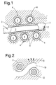
- Figure 1 schematically illustrates a simple cross light transmission element arrangement in which a lateral light transmission element 1 having a core 2 and sheath 3 is contacted by cross light transmission elements 4 including a respective core 5 and sheath 6. Light may be coupled between the respective light transmission elements 1, 4 to the sheaths 3, 6 and into the cores 2, 5 for distribution through a polymer matrix 7 forming a component.
- certain light transmission elements may be designated as primary or trunk distribution elements with other transmission elements then tapping light transmission from the trunk elements as required.
- selected areas of the polymer matrix 7 may be exposed to ultraviolet light for curing purposes.
- a light transmission element 10 is arranged in a weave pattern with other elements which may be light transmitting elements or reinforcing elements and fibres 11, 12.
- these further fibres 11, 12 cause a tight bend in the light transmission element 10 such that there is light transmission in the direction of the arrowheads 13.
- this leaked ultraviolet light 13 will locally cure a polymer matrix in the vicinity of the bend 10 and so create localised curing as required.
- in-situ ultraviolet light sources may be stimulated to provide ultraviolet light to light transmission elements for appropriate distribution and curing. In such circumstances attenuation and losses of the ultraviolet light may be more easily accommodated.
Landscapes
- Physics & Mathematics (AREA)
- Health & Medical Sciences (AREA)
- Thermal Sciences (AREA)
- Oral & Maxillofacial Surgery (AREA)
- Mechanical Engineering (AREA)
- Chemical & Material Sciences (AREA)
- Composite Materials (AREA)
- Engineering & Computer Science (AREA)
- Electromagnetism (AREA)
- Toxicology (AREA)
- Surface Treatment Of Glass Fibres Or Filaments (AREA)
- Reinforced Plastic Materials (AREA)
- Polymerisation Methods In General (AREA)
Abstract
Description
- The present invention relates to polymer components and more particularly to polymer components utilising ultraviolet curable polymers and resins.
- It is known to form components utilising polymers and in particular curable polymers in a wide number of industries and in relation to a wide range of components. Traditionally other than with regard to thin components the normal techniques for producing a cured polymer component is either through a two part solvent based or resin based polymer curing process or through use of heat to activate curing of the polymer.
- With regard to the solvent and two part processes activation is typically achieved through a lay up of the solvent based or two part (resin and hardener) polymer combinations within a mould and then heat in applied to activate and accelerate the curing procedure until a desired finished component structure is achieved. Other techniques as indicated to stimulate curing of polymers include simply applying heat possibly delivered through an external source such as within an oven or utilising infrared heat or utilising dyes or selected filters within the resin to react with light or heating with microwaves or applying electric current to conductive fibres including carbon fibres to generate heat or chemical reaction heat or utilising a trigger catalyst which may be triggered by a particular frequency of light. There are also chemical methods which may delay the curing process to allow assembly of uncured components before the curing reaction completes. Finally, it is also known to coat reinforcing fibres with a catalyst which again will start curing when combined with the polymer or resin.
- A particular problem with such traditionally chemical or heat curing is that during the curing process the fibre reinforced polymer shrinks. Shrinkage is usually restrained by fibre stiffness and also by mould shape where applicable. Shrinkage is as a result of molecular changes in the polymer as it changes from an amorphous liquid to a more stabilised solid and also, particularly when solvents are used release of volatiles from the cured polymer. It will also be understood that the curing process is often performed at elevated temperatures and in any event the curing process itself may be exothermic that is to say releases further heat as a result of the molecular changes. In such circumstances as the component cures and then cools residual tensile stresses build up within the component leading to particularly compressive residual stresses at the surface and within the fibres. The tensile residual stresses can lead to matrix cracking and leave the components susceptible to early tensile or fatigue failure. It will be understood that the fibres are essentially string like and therefore are substantially stronger in tension than compression. Compressive residual stresses in fibres allow them to buckle in situ which in turn reduces component stiffness and predisposes the reinforcing fibres to failure in bending. It will also be understood that with relatively thin components incorporating particularly reinforcing weave patterns that shrinkage can occur generally within one axis. This shrinkage may be further exacerbated by moulding pressure in the axis of shrinkage and can result in an anisotropic material performance. This is not always desirable.
- In view of the above it will be appreciated that shrinkage in the polymer matrix during curing is detrimental so that reduction in shrinkage as well as fibre buckling has advantages.
- It is known that some ultraviolet curable polymers currently available have no or limited shrinkage upon stability and forming. Unfortunately by their nature ultraviolet curable polymers must be exposed to ultraviolet to be cured and in such circumstances formation of thicker components is therefore difficult. It will be appreciated that ultraviolet light will only penetrate to a certain depth. With regard to opaque components or components incorporating opaque fibres for reinforcement ultraviolet curing to a significant depth through surface exposure is not possible.
- In accordance with the present invention there is provided a polymer component comprising an ultraviolet curable polymer and a method of curing an ultraviolet curable polymer in a component, as set out in the claims.
- Embodiments of the invention will now be described by way of example with reference to the accompanying drawings in which: -
-
Figure 1 is a schematic cross section of a light transmission element arrangement in accordance with the invention; and, -
Figure 2 is a schematic cross section of a structurally pre-stressed light transmission element arrangement in accordance with the invention. - As indicated above a number of ultraviolet curable polymers are available which present no or limited shrinkage upon curing. Such resins include CYRACURE™ cycloaliphatic epoxides and cationic UV-curable resins, available from The Dow Chemical Company. These ultraviolet curable polymers also have particular advantages in that no solvents are utilised or emitted during processing and so there are reduced requirements for environmental protection against such solvents. The polymers generally comprise a resin combined with an epoxy, acrylic or polyurethane base matrix or substrate. As indicated above with thin structures and panels ultraviolet light can be applied relatively easily through the outer surfaces of the component. Thus, for a simple weave or single braid, or for a thin structure, the light conduction of the polymer resin is adequate to assure a full cure of the thin panel component formed by the ultraviolet curable polymer.
- A further advantage with regard to use of ultraviolet curable resins is that as heat and chemical action is not required for curing it is possible to use a wider range of the materials including low temperature materials such as plastics, visco-fibre and polypropylene within the component structure along with materials which impart particular properties such as moisture detection and/or sensing along with damping through elastic deformation. However, some of these materials may be sensitive to ultraviolet and therefore may require an ultraviolet impermeable coating or sizing to be applied to protect their function. Furthermore, in structures which are multi layered, it will be understood that relatively solid outer woven layers or otherwise are presented which are opaque to ultraviolet light then in accordance with conventional practice they will be a severe limitation with regard to ultraviolet curing of layers other than those outer layers exposed directly to ultraviolet light externally.
- In accordance with the present invention a number of solutions are presented to enable ultraviolet curable polymers to be utilised in forming polymer components and their use.
- It will be appreciated that one disadvantage with some ultraviolet curable polymers is that they are continuously cured by ambient ultraviolet emissions and therefore can eventually become over cured and brittle. Solutions in accordance with aspect of the present invention enable utilisation of a low temperature less aggressive curing procedures with ultraviolet curable polymers whilst maintaining adequate control of the component structure post formation.
- A first solution is to provide light transmitting elements and normally a large number of such elements within a structure of a polymer component. The light transmitting elements will typically be part of the reinforcing structure for that component but nevertheless will generally reduce the ratio of high strength reinforcing fibres within the polymer component. In accordance with the present invention the light transmitting elements may incorporate light transmitting fillers within the curable polymer itself along with chopped light transmitting elements. In such circumstances the number of continuous light transmitting elements required may reduce due to the distributive nature of the light transmitting fillers and typically randomly orientated chopped light transmitting fibres.
- It will be appreciated that it is transmission of ultraviolet light into the depths of the polymer component which is a particular requirement. In such circumstances, in accordance with the present invention light transmitting elements are presented as pins or strands which extend with a vertical aspect into the depth of the polymer component. The transmitting elements act as light distribution mechanisms to the interior of the component to precipitate ultraviolet curing of ultraviolet curing polymers. These pins may take the form of staples or a stitched fibre extending through the depth of the component. These pins may also perform the structural 'Z'-pinning of the fibre layers.
- In the field of optics generally, it is known to use hollow optical fibres. It is known that such fibres have greater flexibility and consequently tighter bend radii are possible. Cores of optical glass or of other materials may be inserted into the hollow interior of such fibres.
- Light distribution may be further enhanced by including notches, indents, ridges or surface gratings in the pins or light transmitting elements to act as distribution exit points for light into the component to cure adjacent polymer. In the field of optical measurement it is known to use gratings or ridges as part of an optical measurement system.
- A conventional form of light transmitting element is an optic fibre. Such optic fibres typically comprise various grades of refractivity across the width of the optic fibre. In such circumstances light can be transmitted along the fibre. A particular benefit with regard to the present invention is that optic fibres have great flexibility and the ability to achieve tight bend radii (compared to, say, a carbon fibre).
- With regard to optic fibres configured to act as light transmitting elements in accordance with the present invention it will be appreciated that consideration will be made as to the best ultraviolet light frequency for curing the ultraviolet curable resin polymer. In such circumstance the appropriate core can be chosen for the optic fibre to deliver preferentially the best ultraviolet light frequency for curing of the particular polymer.
- A particular advantage with regard to optic fibres is that when squashed or bent some of the transmitted light will escape through the refractive index shielding. In such circumstances localised distribution and concentration of ultraviolet light can be achieved. Furthermore, the ultraviolet light transfer from the optical fibre can be varied as the light transmitting element is tightly bent. A designer of a polymer component in such circumstances can therefore incorporate structural and substantially fixed light distribution by adopting an appropriate structural weave of light transmitting elements which will include fixed structural tight bends at locations where curing is required. Furthermore, in order to achieve specific localised enhancement of curing the light transmitting elements may be arranged such that specific squashing and bending of the component can be achieved such that ultraviolet light passing along the light transmitting element can be arranged to leak from the light transmitting element and therefore enhance specifically curing at that location.
- As indicated above incorporation of specific light transmitting elements in order to enhance ultraviolet curing can be detrimental in reducing the proportion and ratio of high strength reinforcing fibres within a polymer component. Such reductions in reinforcement may be significant and unacceptable. In such circumstances in accordance with a second solution the reinforcing fibres such as carbon fibres can be adapted to act as light pipes. For example, carbon fibres can be coated with nylon to allow them to be manipulated without fracturing and reduce flaking. It will also be understood that such coating allows tighter bending of the reinforcing carbon fibres without compromising integrity. In accordance with the present invention reinforcing fibres such as carbon fibres are also coated with a light transmitting material such that effectively a light transmitting sheath is provide to the reinforcing fibre. This sheath may be coated itself with a further layer of material with a different refractive index such that the light transmitting material is sandwiched to create an optical pipe for light transmission. In such circumstances as with an optical fibre ultraviolet light can be passed along the light transmitting material coating or sheath of the reinforcing fibre and distributed as necessary in order to stimulate ultraviolet curing in the ultraviolet curable resin or polymer. It will be appreciated that the outer coating in order to create the optic light pipe may be required if the refractive index of the base polymer component is too close to that of the reinforcing fibre and light transmitting material such that light transmission will not occur.
- As indicated above light transmitting elements themselves can be incorporated within the polymer component but such an approach may reduce the functionality of other reinforcing fibres etc. The second solution is to adapt the reinforcing fibres to act as light pipes for transmission but such adaptation of the reinforcing fibres may again diminish effectiveness of those fibres or reduce the capability of the light transmitting elements to an impractical extent. A further third solution is therefore to provide through consideration of a refractive index of the uncured and cured polymer effective paths for light distribution.
- It will be appreciated that as a polymer cures its refractive index varies. In such circumstances, and as is known with regard to forming optic fibres, it is possible to change the refractive index of materials by varying the phosphor and epoxy content or for silicon/quartz fibres by varying the type or degree of doping within the fibre. In accordance with third the present invention already cured polymer resin can be used as cladding for an optical path for light transmission. In such circumstances the cured polymer provides two functions, one is to direct curing and the other is to provide an indication as to the intensity of curing through monitoring when light at full intensity arrives at the far end of the light transmission component indicating complete curing to a desired level. In such circumstances a light transmitting element can be created within the polymer or more typically a light transmission path can be coated with an ultraviolet curable resin which is then cured to a desired extent and to achieve a particular refractive index. The component is thereby "built" up as required. In such circumstances a cured or partially cured coating will continue to cure with the light passing along the light transmission element. The coating to the transmission element may be deliberately masked to prevent light escaping at certain positions or an otherwise fully opaque coated fibre may have areas cleared of opaque sheathing so that localised areas of the polymer can be activated or not activated as they are cured.
- It will also be understood that where light transmitting elements touch, mating together with surface finishes and surface coatings will determine a degree of light transfer between the light transmitting elements. Such mating together may be used to facilitate ultraviolet light distribution.
- In the above circumstances by a combination of one or more of the three solutions as outlined above a light transmission element structure can be located within a polymer component to allow universal or localised specific curing of an ultraviolet curable polymer to a desired level in a component.
- A fourth approach or solution to trigger ultraviolet curing is to provide within the uncured polymer component an ultraviolet light source precursor. This ultraviolet light source precursor will be triggered by an appropriate stimulation mechanism in order to emit ultraviolet light when required. The ultraviolet light source precursor will be associated with the polymer matrix of the component during manufacture and will typically be located through a woven, knitted or braided structure within the polymer matrix at desired locations. Stimulation mechanisms may include heating or vibration but where such stimulation mechanisms are used care must be taken with respect to the ongoing use of the component. It will appreciated that a large number of components will be used in situation where there will be inherent vibration or thermal cycling which may cause further stimulation of the ultraviolet light source and so continued exposure to ultraviolet light which will further harden the ultraviolet curable polymer matrix beyond that which may be desirable. The ultraviolet light source precursor may act through an appropriate chemical reaction and this reaction as indicated may be stimulated by vibration or heat or alternatively may be triggered by initial exposure to a primary light source distributed through light transmission elements as described above. In such circumstances relatively low intensity light transmission through the light transmission elements may stimulate and achieve higher intensity light source emissions and so enhance curing locally.
- As it will be appreciated by provision of the above approaches and embodiments enhanced and shorter curing times are provided for ultraviolet curable polymers with thicker configurations. Advantageously the light transmitting elements will be an integral part of the component structure and reinforcement of the structure. Furthermore, as the light transmitting elements can take the form of optic fibres these fibres can be utilised as embedded instrumentation sensors within the component. Alternatively, the light transmitting elements may be relatively passive once the function of curing has been achieved. Utilisation of ultraviolet curable polymers has particular advantages with regard to removing the necessity of using volatile solvents in forming polymer components. Additionally, ultraviolet light cured polymers generally remove the necessity for higher temperatures and therefore allow a wider range of sensors including sensors utilising lower temperature materials to be incorporated within a polymer component structure.
- As indicated above inherently ultraviolet cured polymers require exposure to ultraviolet light to be cured or fully cured. In such circumstances with thicker component geometries or ultraviolet light opaque surfaces unless ultraviolet light is presented to the ultraviolet light curable polymer that polymer will remain none activated. An advantage with such an approach is that pockets or sections of the component may be left un-activated. In such circumstances provided appropriate light transmission elements can be located without detriment to the overall structural integrity of an component during manufacturing processes and these light transmission paths not used in curing during those manufacturing processes it will be possible to utilise the un-activated resin when required. Thus, should there be instances of erosion or damage the un-activated resin can be released into the damaged area and cured by ambient radiation or by specific application of ultraviolet light through the previously unused light transmission elements to repair the damaged area. It will be appreciated particularly with regard to components utilising in aircraft that at the altitude that aircraft fly at there will be sufficient ambient ultraviolet radiation to achieve curing and stiffening.
- It will be understood that in accordance with the present invention that the light transmission elements, whether specific elements in the form of optic fibres, coatings to existing reinforcing fibres or created by judicious curing to achieve refractive index grading will remain within the polymer component after manufacture. In such circumstances paths within the component will remain and therefore may give an indication as to continuing sunlight and/or ultraviolet light intensity exposure of the component during its operational life.
- The present invention incorporates a method of curing a polymer component including an ultraviolet curable polymer resin. The method includes locating light transmitting elements or forming such elements within the uncured polymer components and then applying ultraviolet light to those light transmitting elements to cure the ultraviolet curable polymer as required. A method in accordance with alternative or additional aspects of the present invention also includes incorporating ultraviolet light source precursors within the uncured polymer and providing a stimulation mechanism either through heat, vibration or trigger light such that the precursor sources emits ultraviolet light to cure locally ultraviolet curable polymer.
- As indicated above with regard to certain aspects of the present invention light transmitting elements are advantageous for transmitting ultraviolet light to interior parts of a polymer component. These light transmitting elements can be combined in order to provide a weave, knit, braid or network within the polymer component. The light transmitting elements in such circumstances may touch each other to facilitate distribution of light within the network.
Figure 1 schematically illustrates a simple cross light transmission element arrangement in which a lateral light transmission element 1 having acore 2 andsheath 3 is contacted by crosslight transmission elements 4 including arespective core 5 andsheath 6. Light may be coupled between the respectivelight transmission elements 1, 4 to thesheaths cores - As indicated above bending and squashing of light transmission elements and in particular optic fibres can create leakage of light. In such circumstances and as depicted in
figure 2 alight transmission element 10 is arranged in a weave pattern with other elements which may be light transmitting elements or reinforcing elements andfibres further fibres light transmission element 10 such that there is light transmission in the direction of thearrowheads 13. In such circumstances this leakedultraviolet light 13 will locally cure a polymer matrix in the vicinity of thebend 10 and so create localised curing as required. - It will also be understood that the aspects of the present invention described above may be combined. Thus, in-situ ultraviolet light sources may be stimulated to provide ultraviolet light to light transmission elements for appropriate distribution and curing. In such circumstances attenuation and losses of the ultraviolet light may be more easily accommodated.
- Modifications and alterations to the present invention will be appreciated by those skilled in the art. Thus, for example conventionally distribution and size of the light transmitting elements will be consistent throughout the polymer component. However alternatively, different sized in terms of diameter and curability light transmission elements may be located and distributed for specific functions throughout the polymer component to achieve enhanced or controlled localised curing depending upon requirements within the polymer component. In such circumstances parts of the polymer component may be hardened extensively by curing whilst other parts are only partially cured to remain possibly flexible.
Claims (15)
- A polymer component comprising an ultraviolet curable polymer with an embedded element to provide ultraviolet light within the component to cure the ultraviolet curable polymer.
- A component as claimed in claim 1 wherein the embedded element comprises one or more optic fibres.
- A component as claimed in claim 1 or claim 2 wherein the embedded element is locally stressed to provide leakage of light thereabout for curing the ultraviolet curable polymer.
- A component as claimed in any preceding claim wherein the light transmitting element incorporates one or more notches or indents or ridges or gratings to facilitate distribution of ultraviolet light within the polymer component.
- A component as claimed in any preceding claim wherein the embedded element is provided by coating an opaque fibre to create a light pipe.
- A component as claimed in any preceding claim where the embedded element is provided by regulating the refractive index of the polymer about the light transmitting element to regulate presentation of the ultraviolet light within the component.
- A component as claimed in any preceding claim where the embedded element comprises an ultraviolet light source precursor and a stimulation mechanism to stimulate the ultraviolet light source precursor.
- A method of curing an ultraviolet curable polymer in a component including embedding an element within the uncured component and providing ultraviolet light from the embedded element.
- A method as claimed in claim 8 wherein the embedded element comprises one or more optic fibres.
- A method as claimed in claim 8 or claim 9 wherein the embedded element is locally stressed to provide leakage of light thereabout for curing the ultraviolet curable polymer.
- A method as claimed in any of claims 8 to 10 wherein the light transmitting element incorporates one or more notches or indents or ridges or gratings to facilitate distribution of ultraviolet light within the polymer component.
- A method as claimed in any of claims 8 to 11 wherein the embedded element is provided by coating an opaque fibre to create a light pipe.
- A method as claimed in claim 12 wherein the source of the ultraviolet light is provided by the coating of the opaque fibre.
- A method as claimed in any of claims 8 to 13 wherein the embedded element is provided by regulating the refractive index of the polymer about the light transmitting element to regulate presentation of the ultraviolet light within the component.
- A method as claimed in any of claims 8 to 14 wherein the embedded element comprises an ultraviolet light source precursor and a stimulation mechanism for the ultraviolet light source precursor, the method comprising the step of utilising the stimulation mechanism to stimulate the ultraviolet light source precursor to emit ultraviolet light to the ultraviolet curable polymer to cure the ultraviolet curable polymer.
Applications Claiming Priority (1)
| Application Number | Priority Date | Filing Date | Title |
|---|---|---|---|
| GBGB0711120.6A GB0711120D0 (en) | 2007-06-09 | 2007-06-09 | Polymer components |
Publications (3)
| Publication Number | Publication Date |
|---|---|
| EP2000276A2 true EP2000276A2 (en) | 2008-12-10 |
| EP2000276A3 EP2000276A3 (en) | 2009-04-29 |
| EP2000276B1 EP2000276B1 (en) | 2015-03-18 |
Family
ID=38319044
Family Applications (1)
| Application Number | Title | Priority Date | Filing Date |
|---|---|---|---|
| EP08251737.6A Ceased EP2000276B1 (en) | 2007-06-09 | 2008-05-17 | Polymer components and a method of curing |
Country Status (3)
| Country | Link |
|---|---|
| US (1) | US8779022B2 (en) |
| EP (1) | EP2000276B1 (en) |
| GB (1) | GB0711120D0 (en) |
Cited By (3)
| Publication number | Priority date | Publication date | Assignee | Title |
|---|---|---|---|---|
| WO2012019749A1 (en) * | 2010-08-13 | 2012-02-16 | Thomas Gmbh + Co. Technik + Innovation Kg | Method for producing and monitoring an object at least partially made of plastic, and component |
| WO2013098545A1 (en) * | 2011-12-28 | 2013-07-04 | Wellstream International Limited | Elongate element for flexible pipe body and method |
| WO2018046118A1 (en) * | 2016-09-10 | 2018-03-15 | Audi Ag | Method and device for producing a composite car body component with uv-hardened plastic |
Families Citing this family (1)
| Publication number | Priority date | Publication date | Assignee | Title |
|---|---|---|---|---|
| US20160096353A1 (en) * | 2014-10-07 | 2016-04-07 | The Boeing Company | Structure including a light-curable adhesive and associated method for assembling and curing same |
Citations (2)
| Publication number | Priority date | Publication date | Assignee | Title |
|---|---|---|---|---|
| US20040021255A1 (en) | 2001-12-27 | 2004-02-05 | Bilanin Alan J. | Lossy fiber UV curing method and apparatus |
| GB2423279A (en) | 2005-02-18 | 2006-08-23 | Uvasol Ltd | Changing the state of a body of material |
Family Cites Families (9)
| Publication number | Priority date | Publication date | Assignee | Title |
|---|---|---|---|---|
| US5259055A (en) | 1988-05-23 | 1993-11-02 | The United States Of America As Represented By The Secrtary Of The Navy | Fiber optic microcable produced with radiation cured composite |
| DE68915722T2 (en) * | 1988-12-28 | 1995-01-12 | Ube Nitto Kasei Co | Twisted fiber reinforced plastic structure and process for its manufacture. |
| US5198479A (en) * | 1990-08-24 | 1993-03-30 | Shin-Etsu Chemical Company Limited | Light transmissive epoxy resin compositions and optical semiconductor devices encapsulated therewith |
| US5299274A (en) | 1992-06-25 | 1994-03-29 | Hughes Aircraft Company | Optical fiber laser fusion splicer |
| US6195486B1 (en) | 1998-06-02 | 2001-02-27 | Siecor Operations, Llc | Fiber optic cable having a component with an absorptive polymer coating and a method of making the cable |
| US6208790B1 (en) | 1999-01-28 | 2001-03-27 | The Stewart Group, Inc. | Ultra violet light curable polymer matrix for tight-buffering optical fibers |
| CA2398177A1 (en) * | 2002-08-14 | 2004-02-14 | Gilles Trudeau | Illuminating structure |
| AU2002953099A0 (en) * | 2002-12-04 | 2002-12-19 | Australian Composites Pty Ltd | Reinforced polymer composition |
| US7799249B2 (en) * | 2005-08-09 | 2010-09-21 | Coopervision International Holding Company, Lp | Systems and methods for producing silicone hydrogel contact lenses |
-
2007
- 2007-06-09 GB GBGB0711120.6A patent/GB0711120D0/en not_active Ceased
-
2008
- 2008-05-17 EP EP08251737.6A patent/EP2000276B1/en not_active Ceased
- 2008-06-03 US US12/131,949 patent/US8779022B2/en active Active
Patent Citations (2)
| Publication number | Priority date | Publication date | Assignee | Title |
|---|---|---|---|---|
| US20040021255A1 (en) | 2001-12-27 | 2004-02-05 | Bilanin Alan J. | Lossy fiber UV curing method and apparatus |
| GB2423279A (en) | 2005-02-18 | 2006-08-23 | Uvasol Ltd | Changing the state of a body of material |
Cited By (4)
| Publication number | Priority date | Publication date | Assignee | Title |
|---|---|---|---|---|
| WO2012019749A1 (en) * | 2010-08-13 | 2012-02-16 | Thomas Gmbh + Co. Technik + Innovation Kg | Method for producing and monitoring an object at least partially made of plastic, and component |
| US9770846B2 (en) | 2010-08-13 | 2017-09-26 | Thomas Gmbh + Co. Technik + Innovation Kg | Method for producing and monitoring an object at least partially made of plastic, and component |
| WO2013098545A1 (en) * | 2011-12-28 | 2013-07-04 | Wellstream International Limited | Elongate element for flexible pipe body and method |
| WO2018046118A1 (en) * | 2016-09-10 | 2018-03-15 | Audi Ag | Method and device for producing a composite car body component with uv-hardened plastic |
Also Published As
| Publication number | Publication date |
|---|---|
| EP2000276B1 (en) | 2015-03-18 |
| US8779022B2 (en) | 2014-07-15 |
| US20080306177A1 (en) | 2008-12-11 |
| EP2000276A3 (en) | 2009-04-29 |
| GB0711120D0 (en) | 2007-07-18 |
Similar Documents
| Publication | Publication Date | Title |
|---|---|---|
| US4113349A (en) | Fiber reinforced optical fiber cable | |
| US4239335A (en) | Fiber reinforced optical fiber cable | |
| KR101497784B1 (en) | Elevator suspension and transmission strip | |
| EP2196834B1 (en) | A buffered optical fiber, a telecommunications cable including a plurality of optical fibers, and a method of fabricating such a fiber | |
| RU2564335C2 (en) | Oil field polymer pipe reinforced with fibres and method of its production | |
| EP2000276B1 (en) | Polymer components and a method of curing | |
| GB2078996A (en) | Infrared light transmission fibre | |
| JPWO2003047830A1 (en) | Fiber-reinforced composite material and method for producing the same | |
| ATE286859T1 (en) | RADIATION CURED AND FLAME RETARDANT COATINGS OF OPTICAL FIBER | |
| EP0384995B1 (en) | Flexible tubing with an outer layer containing metal particles | |
| CN115262862B (en) | Steel-continuous fiber composite intelligent bar with sheath optical cable embedded in inner core of steel bar and preparation method thereof | |
| JP6157186B2 (en) | Manufacturing method of fiber reinforced composite material structure | |
| US4211591A (en) | Production of optical fiber cables | |
| Huber | Deuchar Care | |
| Endruweit et al. | Textile composites with integrated optical fibres: quantification of the influence of single and multiple fibre bends on the light transmission using a Monte Carlo ray-tracing method | |
| IL261293A (en) | Feedstock lines for additive manufacturing of an object, and systems and methods for creating feedstock lines | |
| JP7208719B2 (en) | Linear body for optical fiber cable, fiber reinforced optical fiber cable and optical fiber sensor | |
| Pulleti et al. | Experimental and numerical study on postbuckling response of natural fiber based functionally graded hybrid composite plates under uniaxial compression | |
| CA2629209A1 (en) | Flexible insert tube for the lining of pipelines and of ducts, in particular of sewers | |
| KR100716725B1 (en) | Manufacturing method of composite reinforced fiber optic sensor structure | |
| US10611081B2 (en) | Systems and methods for creating feedstock lines for additive manufacturing of an object | |
| WO2016075120A1 (en) | Optical cable with flame retardant tensile strength members | |
| CA2848260A1 (en) | A method of manufacturing a composite material including a thermoplastic coated reinforcing element | |
| GB2179072A (en) | Optical fibre cables | |
| JP7742768B2 (en) | Strain detection optical fiber cable and its manufacturing method |
Legal Events
| Date | Code | Title | Description |
|---|---|---|---|
| PUAI | Public reference made under article 153(3) epc to a published international application that has entered the european phase |
Free format text: ORIGINAL CODE: 0009012 |
|
| AK | Designated contracting states |
Kind code of ref document: A2 Designated state(s): AT BE BG CH CY CZ DE DK EE ES FI FR GB GR HR HU IE IS IT LI LT LU LV MC MT NL NO PL PT RO SE SI SK TR |
|
| AX | Request for extension of the european patent |
Extension state: AL BA MK RS |
|
| 17P | Request for examination filed |
Effective date: 20081113 |
|
| PUAL | Search report despatched |
Free format text: ORIGINAL CODE: 0009013 |
|
| AK | Designated contracting states |
Kind code of ref document: A3 Designated state(s): AT BE BG CH CY CZ DE DK EE ES FI FR GB GR HR HU IE IS IT LI LT LU LV MC MT NL NO PL PT RO SE SI SK TR |
|
| AX | Request for extension of the european patent |
Extension state: AL BA MK RS |
|
| 17Q | First examination report despatched |
Effective date: 20090729 |
|
| AKX | Designation fees paid |
Designated state(s): DE FR GB |
|
| GRAP | Despatch of communication of intention to grant a patent |
Free format text: ORIGINAL CODE: EPIDOSNIGR1 |
|
| INTG | Intention to grant announced |
Effective date: 20141127 |
|
| GRAS | Grant fee paid |
Free format text: ORIGINAL CODE: EPIDOSNIGR3 |
|
| GRAA | (expected) grant |
Free format text: ORIGINAL CODE: 0009210 |
|
| AK | Designated contracting states |
Kind code of ref document: B1 Designated state(s): DE FR GB |
|
| REG | Reference to a national code |
Ref country code: GB Ref legal event code: FG4D |
|
| REG | Reference to a national code |
Ref country code: DE Ref legal event code: R096 Ref document number: 602008037181 Country of ref document: DE Effective date: 20150430 |
|
| RAP2 | Party data changed (patent owner data changed or rights of a patent transferred) |
Owner name: ROLLS-ROYCE PLC |
|
| REG | Reference to a national code |
Ref country code: DE Ref legal event code: R097 Ref document number: 602008037181 Country of ref document: DE |
|
| PLBE | No opposition filed within time limit |
Free format text: ORIGINAL CODE: 0009261 |
|
| STAA | Information on the status of an ep patent application or granted ep patent |
Free format text: STATUS: NO OPPOSITION FILED WITHIN TIME LIMIT |
|
| 26N | No opposition filed |
Effective date: 20151221 |
|
| REG | Reference to a national code |
Ref country code: DE Ref legal event code: R082 Ref document number: 602008037181 Country of ref document: DE Representative=s name: HERNANDEZ, YORCK, DIPL.-ING., DE |
|
| REG | Reference to a national code |
Ref country code: FR Ref legal event code: PLFP Year of fee payment: 9 |
|
| REG | Reference to a national code |
Ref country code: FR Ref legal event code: PLFP Year of fee payment: 10 |
|
| PGFP | Annual fee paid to national office [announced via postgrant information from national office to epo] |
Ref country code: FR Payment date: 20170525 Year of fee payment: 10 Ref country code: GB Payment date: 20170530 Year of fee payment: 10 Ref country code: DE Payment date: 20170530 Year of fee payment: 10 |
|
| REG | Reference to a national code |
Ref country code: DE Ref legal event code: R119 Ref document number: 602008037181 Country of ref document: DE |
|
| GBPC | Gb: european patent ceased through non-payment of renewal fee |
Effective date: 20180517 |
|
| PG25 | Lapsed in a contracting state [announced via postgrant information from national office to epo] |
Ref country code: FR Free format text: LAPSE BECAUSE OF NON-PAYMENT OF DUE FEES Effective date: 20180531 Ref country code: GB Free format text: LAPSE BECAUSE OF NON-PAYMENT OF DUE FEES Effective date: 20180517 Ref country code: DE Free format text: LAPSE BECAUSE OF NON-PAYMENT OF DUE FEES Effective date: 20181201 |