EP2000260A2 - Device and method for elid honing - Google Patents
Device and method for elid honing Download PDFInfo
- Publication number
- EP2000260A2 EP2000260A2 EP06797679A EP06797679A EP2000260A2 EP 2000260 A2 EP2000260 A2 EP 2000260A2 EP 06797679 A EP06797679 A EP 06797679A EP 06797679 A EP06797679 A EP 06797679A EP 2000260 A2 EP2000260 A2 EP 2000260A2
- Authority
- EP
- European Patent Office
- Prior art keywords
- honing
- elid
- guide
- stones
- electrode
- Prior art date
- Legal status (The legal status is an assumption and is not a legal conclusion. Google has not performed a legal analysis and makes no representation as to the accuracy of the status listed.)
- Granted
Links
Images


Classifications
-
- B—PERFORMING OPERATIONS; TRANSPORTING
- B24—GRINDING; POLISHING
- B24B—MACHINES, DEVICES, OR PROCESSES FOR GRINDING OR POLISHING; DRESSING OR CONDITIONING OF ABRADING SURFACES; FEEDING OF GRINDING, POLISHING, OR LAPPING AGENTS
- B24B53/00—Devices or means for dressing or conditioning abrasive surfaces
- B24B53/001—Devices or means for dressing or conditioning abrasive surfaces involving the use of electric current
-
- B—PERFORMING OPERATIONS; TRANSPORTING
- B24—GRINDING; POLISHING
- B24B—MACHINES, DEVICES, OR PROCESSES FOR GRINDING OR POLISHING; DRESSING OR CONDITIONING OF ABRADING SURFACES; FEEDING OF GRINDING, POLISHING, OR LAPPING AGENTS
- B24B33/00—Honing machines or devices; Accessories therefor
- B24B33/02—Honing machines or devices; Accessories therefor designed for working internal surfaces of revolution, e.g. of cylindrical or conical shapes
-
- B—PERFORMING OPERATIONS; TRANSPORTING
- B24—GRINDING; POLISHING
- B24B—MACHINES, DEVICES, OR PROCESSES FOR GRINDING OR POLISHING; DRESSING OR CONDITIONING OF ABRADING SURFACES; FEEDING OF GRINDING, POLISHING, OR LAPPING AGENTS
- B24B33/00—Honing machines or devices; Accessories therefor
- B24B33/08—Honing tools
- B24B33/083—Honing tools with different sets of honing stones
-
- B—PERFORMING OPERATIONS; TRANSPORTING
- B24—GRINDING; POLISHING
- B24B—MACHINES, DEVICES, OR PROCESSES FOR GRINDING OR POLISHING; DRESSING OR CONDITIONING OF ABRADING SURFACES; FEEDING OF GRINDING, POLISHING, OR LAPPING AGENTS
- B24B33/00—Honing machines or devices; Accessories therefor
- B24B33/10—Accessories
-
- B—PERFORMING OPERATIONS; TRANSPORTING
- B24—GRINDING; POLISHING
- B24B—MACHINES, DEVICES, OR PROCESSES FOR GRINDING OR POLISHING; DRESSING OR CONDITIONING OF ABRADING SURFACES; FEEDING OF GRINDING, POLISHING, OR LAPPING AGENTS
- B24B53/00—Devices or means for dressing or conditioning abrasive surfaces
- B24B53/12—Dressing tools; Holders therefor
Definitions
- the present invention relates to device and method for ELID honing for a hollow cylindrical inner surface.
- a honing device is conventionally used for machining of cylinder bores of automobile engines or the like.
- the honing device gives contact pressure radially outward to a square rod-shaped grinding stone in contact with a cylindrical inner surface, and gives reciprocating motion axially to a workpiece over its total length while rotating a honing head.
- special machining streaks called cross hatching are formed on the inner surface of the workpiece. This cross hatching has a function to hold lubricating oil required in cylinder bores of engines or the like.
- a grinding stone i.e., a grinding stone having high autogenous action such that the grinding stone itself is dressed (sharpened, hereinafter called "dressing" for short) simultaneously when machining the workpiece is selected.
- dressing of the grinding stone depends on the autogenous action of the grinding stone itself, the cycle of the autogenous action is also influenced due to variations in machining accuracy in a previous process, manufacturing variations of the grinding stone, contamination of coolant, etc. Therefore, in the conventional honing, it was necessary to frequently dress the grinding stone in order to solve clogging of a grinding stone, deterioration of surface roughness of a workpiece, extension of machining time, etc.
- Patent Documents 1 to 3 are already disclosed.
- Dressing means of Patent Document 1, as shown in Fig. 1 is one in which a tubular grinding stone dressing member 52 is supported by a turning member 50 in a position above a workpiece 51, the internal diameter of the grinding stone dressing member 52 is set to be approximately equal to the machining diameter of a grinding stone 58 in a honing tool 53, and a dressing grinding stone 54 for dressing the grinding stone 58 is disposed on the inner surface of the grinding stone dressing member 52.
- this dressing means while machining is performed by the honing tool 53, the honing tool 53 is inserted into the grinding stone dressing member 52 with suitable timing, and each grinding stone 58 is made to project, and is brought into contact with the dressing grinding stone 54.
- the grinding stone can be dressed with the grinding stone mounted on the honing tool by suitably driving the honing tool 53 reciprocally in its axial direction, and rotationally driving the honing tool.
- the dressing means of Patent Document 2 is one which performs the grinding stone dressing of bringing a grinding stone 63 provided at an outer peripheral portion of a honing head 61 into sliding contact with dressing abrasive 65 made of the same material as a workpiece to be machined by this honing head, thereby removing used abrasive grains on the surface of the grinding stone, and exposing new abrasive grains on the grinding stone surface.
- the dressing of the grinding stone is performed using dressing abrasive made of the same material as a workpiece.
- the grinding stone when used abrasive grains cut from tips of the surface of the grinding stone are removed, and new abrasive grains whose tips become sharp cutting edges are exposed, the grinding stone is not used as the dressing abrasive even if the tips of the new abrasive grains grind the dressing abrasive at the time of dressing.
- troubles such as abrasion of cutting edges at the tip of the grinding stone, and entering of abrasive grains on the side of the dressing abrasive into between the cutting edges of the grinding stone in the honing head, is avoided, so that proper grinding stone dressing can be performed.
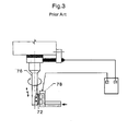
- the dressing means of Patent Document 3, as shown in Fig. 3 is one in which a metal-bonded grinding stone 72 for honing including abrasive grains, and a conductive binder which fixes these grains is fixed to a grinding stone holder 76 for electrolytic dressing, an electrode 78 is made to face a grinding stone machining surface with a predetermined spacing therefrom, and a predetermined voltage is applied to between the grinding stone and the electrode, and simultaneously, conductive grinding lubricant is supplied between the grinding stone and the electrode, thereby electrolytically dressing of metal-bonded portions on the surface of the grinding stone.
- the metal-bonded portions on the surface of the grinding stone can be electrolytically dressed selectively.
- the amount of projections of the abrasive grains can be optimized depending on electrolytic voltage and time, and machining with small machining load and higher efficiency can be stabilized.
- the dressing means of Patent Document 1 has the structure in which the cylindrical dressing grinding stone and the insertion guide are reversed 180°.
- additional processes such as reversion of the cylindrical dressing grinding stone, positioning of the height of the dressing grinding stone, and the rotation of the dressing grinding stone, become necessary. Therefore, time loss is caused, and the honing cycle becomes long due to dressing time.
- time loss is caused, and the honing cycle becomes long due to dressing time.
- there is neither reference of completion of the dressing nor reference of timing with which dressing is performed it cannot determined that machining accuracy is not measured. Therefore, adaptation is difficult for the mass production line where continuous operation is made.
- the replacement time of a dressing grinding stone is also indefinite.
- the same material as a workpiece is used as the dresser without providing a dressing grinding stone.
- dressing cannot be performed during machining, it is necessary to perform the dressing in another cycle. Thus, the time loss is heavy.
- the electrode has a circular-arc shape. Therefore, it is necessary to position the metal-bonded grinding stone 72 at the same height as the electrode 78, and to rotate the metal-bonded grinding stone 72 in that height, and extra dressing processes (cycle peculiar to the dressing) is required.
- the object of the invention is to ELID honing device and method, capable of dressing a honing stone without additional processes (cycle peculiar to dressing), and thereby, preventing clogging of the grinding stone, deterioration of surface roughness, extension of machining time, etc. for a prolonged period of time without changing a honing cycle, and allowing adaptation to a mass production line where continuous operation is made, and preventing electrolytic corrosion of a workpiece.
- an ELID honing device comprising a honing tool positioned above a workpiece having a hollow cylindrical inner surface to be honed, and vertically movable and rotationally drivable about a vertical rotation axis while being rockably suspended from an upper end, and a honing guide positioned in proximity to an upper portion of the workpiece to guide the honing tool to the hollow cylindrical inner surface.
- the honing tool has a fixed guide having a predetermined radius R from the rotation axis to its outer peripheral surface, and honing stones having outer peripheral surfaces movable in parallel from a diameter-increased position outside the radius R to a diameter-reduced position inside the radius and capable of being electrolytically dressed.
- the honing guide has a hollow cylindrical ELID electrode having an inner surface for guiding an outer peripheral surface of the fixed guide of the honing tool and capable of being subjected to a negative voltage.
- the honing guide has a grinding lubricant supply port which almost uniformly supplies conductive grinding lubricant to a gap between the ELID electrode and a honing stone passing through the inside of the electrode.
- the honing guide has a corrosion-resistant electrode positioned below the ELID electrode, close to the upper portion of the workpiece, and capable of being subjected to a positive voltage.
- an ELID honing method including a honing tool positioned above a workpiece having a hollow cylindrical inner surface to be honed, and vertically movable and rotationally drivable about a vertical rotation axis while being rockably suspended from an upper end, and a honing guide positioned in proximity to an upper portion of the workpiece to guide the honing tool to the hollow cylindrical inner surface.
- the honing tool has a fixed guide having a predetermined radius R from the rotation axis to its outer peripheral surface, and honing stones having outer peripheral surfaces movable in parallel from a diameter-increased position outside the radius R to a diameter-reduced position inside the radius and capable of being electrolytically dressed.
- the honing guide has a hollow cylindrical ELID electrode having an inner surface for guiding an outer peripheral surface of the fixed guide of the honing tool and capable of being subjected to a negative voltage.
- the honing method includes pouring a conductive grinding lubricant into a gap between the honing stones and the ELID electrode to electrolytically dress the honing stones while the honing stones are held in the diameter-reduced position and the fixed guide of the honing tool is guided by an inner surface of the ELID electrode; and then inserting the honing tool into the workpiece, and thereafter moving the honing stones to the diameter-increased position and rotationally driving the moving stones to hone the hollow cylindrical inner surface.
- the honing tool is caused to descend or ascend while being guided, and simultaneously the honing stones are electrolytically dressed.
- the honing stones are electrolytically dressed without rotation of the honing tool or with the rotation of the honing tool, with the honing stones held in the diameter-reduced position.
- the conductive grinding lubricant is poured into the gap between the honing stones and the ELID electrode to electrolytically dress the honing stones while the honing stones are held in the diameter-reduced position and the fixed guide of the honing tool is guided by the inner surface of the ELID electrode.
- the honing stones can be dressed without additional processes (cycle peculiar to dressing). Accordingly, clogging of a grinding stone, deterioration of surface roughness, extension of machining time, etc. can be prevented for a prolonged period of time without changing a honing cycle, and adaptation to a mass production line where continuous operation is made is allowed.
- an electric current flows into the corrosion-resistant electrode via the coolant (conductive grinding lubricant) interposed between the corrosion-resistant electrode and the electrode for ELID by providing the honing guide with the corrosion-resistant electrode which is positioned below the ELID electrode, is close to the upper portion of the workpiece, and is capable of being subjected to a positive voltage.
- electrolytic corrosion of the workpiece can be prevented by suppressing electrolysis of the workpiece.
- Fig. 4 is a configuration diagram of a honing tool of the invention.
- the honing tool 10 of the invention is positioned above a workpiece 1 (not shown) having a hollow cylindrical inner surface to be honed, such as cylinder bores of an engine, and is configured so as to be vertically movable and rotationally drivable about a vertical rotation axis Z while being rockably suspended from an upper end thereof, by means of a driving unit 2 (honing head).
- the honing tool 10 has a fixed guide 12 and honing stones 14a and 14b.
- the fixed guide 12 has a constant radius R from the rotation axis Z to an outer peripheral surface.
- the fixed guide 12 is made of insulating materials, such as ceramic, and three or more fixed guides are provided at regular integrals in the peripheral direction.
- the honing tool 10 contains an air micro unit (not shown) which makes precision measurement of a gap between the outer surface of the fixed guide 12, and a machining surface close thereto.
- the honing stones 14a and 14b are configured such that their outer peripheral surfaces are movable in parallel from a diameter-increased position outside the radius R of the outer peripheral surface of the fixed guide 12 to a diameter-reduced position inside the radius.
- the honing stones 14a and 14b are, for example, metal-bonded grinding stones including abrasive grains and a conductive binder which fixes these grains.
- the honing stone 14a which is a grinding stone for roughening, is fixed to an outer periphery of a first expansion/contraction member 16a which is provided so as to be movable radially, and is moved in parallel from the diameter-increased position to the diameter-reduced position by the axial movement of a first expansion/contraction shaft 17a including a tapered outer surface which rubs a tapered inner surface of the first expansion/contraction member 16a.
- the honing stone 14b which is a grinding stone for finishing, is fixed to an outer periphery of a second expansion/contraction member 16b which is provided so as to be movable radially, and is moved in parallel from the diameter-increased position to the diameter-reduced position by the axial movement of a second expansion/contraction shaft 17b including a tapered outer surface which rubs a tapered inner surface of the second expansion/contraction member 16b.
- the first expansion/contraction shaft 17a and second expansion/contraction shaft 17b is adapted to be capable of being driven at any time during use of the honing tool 10 by the driving unit which is not shown.
- honing stones 14a and 14b are configured such that they are connected to a positive electrode (+ electrode) of a power source for electrolytic dressing (ELID power source) which is not shown, and are capable of being subjected to a positive voltage.
- a power source for electrolytic dressing (ELID power source) which is not shown, and are capable of being subjected to a positive voltage.
- Fig. 5 is a configuration diagram of a honing guide of the invention.
- the honing guide 20 of the invention is positioned in proximity with an upper portion of the workpiece 1 having a hollow cylindrical inner surface to be honed, and has a function to guide the honing tool 10 to the hollow cylindrical inner surface of the workpiece 1.
- the honing guide 20 has an ELID electrode 22.
- the ELID electrode 22 has an inner surface 22a which guides the outer peripheral surface of the fixed guide 12 of the honing tool 10, and is configured such that it is capable of being subjected to a negative voltage via a terminal 22b connected to a negative electrode (-electrode) of the power source for electrolytic dressing (ELID power source) which is not shown.
- the ELID electrode 22 preferably has a hollow cylindrical shape without cut, it may include a plurality of circular-arc surfaces, and there may be a cut between the circular-arc surfaces.
- the vertical length of the ELID electrode 22 is preferably equal to or greater than that of the honing stones 14a and 14b, it may be shorter than the vertical length of the honing stones.
- guide body 24 represents a hollow cylindrical guide body which surrounds the ELID electrode 22
- reference numeral 25 is an insulating ring which is positioned between the ELID electrode 22 and the guide body 24 to insulate them therefrom.
- the honing guide 20 further has a grinding lubricant supply port 26.
- the grinding lubricant supply port 26 which is a plurality of through holes provided obliquely downward in the upper portion of the guide body 24, is adapted to almost equally supply conductive grinding lubricant (coolant) to a gap between the ELID electrode 22 and the honing stones 14a and 14b which pass through the inside of the electrode, via a flow passage 3a provided in a fixing member 3 of the honing guide 20.
- the honing guide 20 further has a corrosion-resistant electrode 28 below the ELID electrode 22.
- the corrosion-resistant electrode 28 is close to an upper portion of the workpiece 1, and is connected to the positive electrode (+ electrode) of the power source for electrolytic dressing (ELID power source) which is not shown, and is capable of being subjected to a positive voltage.
- the corrosion-resistant electrode 28 and the guide body 24 are connected together by a conductive bolt 27, and both of them are capable of being subjected to a positive voltage.
- Fig. 6 is a configuration diagram of an ELID honing device of the invention, showing a state where the honing stones 14a and 14b are electrolytically dressed.
- the conductive grinding lubricant 4 is poured into the gap between the honing stones 14a and 14b and the ELID electrode 22 to electrolytically dress the honing stones 14a and 14b while the honing stones 14a and 14b are held in the diameter-reduced position and the fixed guide 12 of the honing tool 10 is guided by the inner surface 22a of the ELID electrode.
- the gap between the honing stones 14a and 14b in the diameter-reduced position and the ELID electrodes 22 is set to the spacing suitable for electrolytic dressing, for example, about 1 to 5 mm.
- the honing tool 10 it is preferable to raise or lower the honing tool 10 while being guided by the honing guide 20, and to electrolytically dress the honing stones 14a and 14b simultaneously.
- the honing tool may be stopped in an intermediate position if necessary.
- the honing tool may be rotated if necessary.
- the honing stones 14a and 14b are moved to the diameter-increased position to rotationally drive the honing tool 10 and to hone the hollow cylindrical inner surface of the workpiece 1.
- the conductive grinding lubricant 4 is poured into the gap between the honing stones 14a and 14b and the ELID electrode 22 to electrolytically dress the honing stones 14a and 14b while the honing stones 14a and 14b are held in the diameter-reduced position and the fixed guide 12 of the honing tool 10 is guided by the inner surface 22a of the ELID electrode 22.
- the honing stones can be dressed without additional processes (cycle peculiar to dressing). Accordingly, clogging of a grinding stone, deterioration of surface roughness, extension of machining time, etc. can be prevented for a prolonged period of time without changing a honing cycle, and adaptation to a mass production line where continuous operation is made is allowed.
- an electric current flows into the corrosion-resistant electrode 28 via the coolant (conductive grinding lubricant 4) interposed between the corrosion-resistant electrode 28 and the electrode 22 for ELID by providing the honing guide 20 with the corrosion-resistant electrode 28 which is positioned below the ELID electrode 22, is close to the upper portion of the workpiece 1, and is capable of being subjected to a positive voltage.
- electrolytic corrosion of the workpiece can be prevented by suppressing electrolysis of the workpiece 1.
- Fig. 7 is a sequence cycle view showing an example of the invention.
- the vertical stroke represents the ascending/descending operation of the honing tool 10
- the spindle motor represents the rotation (ON) and stop (OFF) of the honing tool 10
- the roughening grinding stone represents expansion/contraction of the honing stone 14a
- the finishing grinding stone represents expansion/contraction of the honing stone 14b
- the dressing timing represents the timing of voltage application of the honing stones 14a and 14b
- the ELID electrode 22 the corrosion-resistant electrode 28.
- the axis of abscissa represents the lapse of time
- the longitudinal arrows represent the timing of the sequence.
- the honing tool 10 descends from the honing guide 20, and after the honing tool 10 is inserted into the hollow cylindrical inner surface of the workpiece 1, the honing tool 10 is made to move up and down while being rotated. Further, a gap from a machining surface is roughened to a predetermined position by expanding the roughening grinding stone, and is detected by an air micro unit. Subsequently, the gap from the machining surface is finished to a predetermined position by expanding the finishing grinding stone. By sequentially repeating these processes, a number of workpieces can be honed without time loss.
- the dressing timing is provided in the ascending operation and descending operation of the vertical stroke.
- This ascending operation and descending operation are operations which cause the honing tool 10 to ascend and descend after completion of honing of a current hollow cylindrical inner surface, thereby allowing the honing tool to be inserted into the honing guide 20, and cause the honing tool 10 to ascend and descend for honing of the next the hollow cylindrical inner surface, and are determined from the cycle time of a mass production line independently of dressing timing.
- Dressing time is set to the time (in this example: 0.2 to 0.3 seconds) sufficiently shorter than the cycle time.
- electrolytic dressing is allowed without changing a honing cycle, clogging of a grinding stone, deterioration of surface roughness, extension of machining time, etc. can be prevented for a prolonged period of time, and adaptation to a mass production line where continuous operation is made is allowed.
- the dressing timing is provided only in any one of the ascending operation and descending operation.
- Fig. 8 is an explanatory view of load curves.
- the left figure illustrates a smoothing roughness curve in evaluation length, and includes projecting peak portions, a core portion, and projecting valley portions.
- the right figure illustrates a linear load curve defined by JIS.
- the load curve is a figure obtained by plotting the load length ratio (tp) on the axis of abscissa and plotting the height (height to cut) direction of a measurement curve on the axis of ordinate.
- R k is the level difference of the core portion
- R pk is the height of the projecting peak portions, and the average height of the projecting peak portions above the core portion
- R vk is the depth of the projecting valley portions and the average depth of the projecting valley portions below the core portion.
- M r1 is the load length ratio of the core portion, and the load length ratio of an intersection points between a parting line of the projecting peak portions and the core portion, and the load curve
- M r2 is the load length ratio of the core portion, and is the load length ratio of an intersection point between a parting line of the projecting valley portion and the core portion, and the load curve.
- R pk height of the projecting peak portions
- the core portion has moderate roughness (for example, about 0.1 to 0.6 Ra) in order to hold lubricating oil.
- Fig. 9A and Fig. 9B are comparison charts of load curves showing the example of the invention.
- Fig. 9A illustrates a conventional example (without ELID)
- Fig. 9B illustrates a case of the invention (with ELID).
- electrolytic dressing conditions are a voltage of 90 V, a current of 2A, and a voltage application time of 1 ⁇ s(ON)/1 ⁇ s(OFF).
- Fig. 10A and Fig. 10B are other comparison charts of machining surface roughness showing the example of the invention.
- Fig. 10A illustrates a conventional example (without ELID)
- Fig. 10B illustrates a case of the invention (with ELID).
- R k level difference of the core portion
- R pk height of the projecting peak portions
- R vk depth of the projecting valley portions
- the invention is ELID honing means in which a special dressing cycle is not provided, and includes the cylindrical electrode 22 also serving as the honing guide disposed on a machining shaft.
- the honing tool 10 is guided by the cylindrical honing guide 20, and is inserted into the workpiece 1.
- the electrode 22 is provided in the honing guide 20, and performs the electrolytic dressing of the honing stones 14a and 14b while the honing tool 10 passes through the cylindrical honing guide 20.
- the honing guide 20 has the structure in which the coolant 4 which allows optimal electrolytic dressing during approach can be supplied.
Landscapes
- Engineering & Computer Science (AREA)
- Mechanical Engineering (AREA)
- Physics & Mathematics (AREA)
- Geometry (AREA)
- Grinding-Machine Dressing And Accessory Apparatuses (AREA)
- Electrical Discharge Machining, Electrochemical Machining, And Combined Machining (AREA)
- Finish Polishing, Edge Sharpening, And Grinding By Specific Grinding Devices (AREA)
Abstract
Description
- The present invention relates to device and method for ELID honing for a hollow cylindrical inner surface.
- A honing device is conventionally used for machining of cylinder bores of automobile engines or the like. The honing device gives contact pressure radially outward to a square rod-shaped grinding stone in contact with a cylindrical inner surface, and gives reciprocating motion axially to a workpiece over its total length while rotating a honing head.
By the honing by the honing device, special machining streaks called cross hatching are formed on the inner surface of the workpiece. This cross hatching has a function to hold lubricating oil required in cylinder bores of engines or the like. - Generally, as the grinding stone for honing, a grinding stone, i.e., a grinding stone having high autogenous action such that the grinding stone itself is dressed (sharpened, hereinafter called "dressing" for short) simultaneously when machining the workpiece is selected.
However, since the dressing of the grinding stone depends on the autogenous action of the grinding stone itself, the cycle of the autogenous action is also influenced due to variations in machining accuracy in a previous process, manufacturing variations of the grinding stone, contamination of coolant, etc.
Therefore, in the conventional honing, it was necessary to frequently dress the grinding stone in order to solve clogging of a grinding stone, deterioration of surface roughness of a workpiece, extension of machining time, etc. - As dressing means of the honing stone,
Patent Documents 1 to 3 are already disclosed. - Dressing means of
Patent Document 1, as shown inFig. 1 , is one in which a tubular grinding stone dressing member 52 is supported by aturning member 50 in a position above aworkpiece 51, the internal diameter of the grinding stone dressing member 52 is set to be approximately equal to the machining diameter of a grindingstone 58 in ahoning tool 53, and adressing grinding stone 54 for dressing thegrinding stone 58 is disposed on the inner surface of the grinding stone dressing member 52.
According to this dressing means, while machining is performed by thehoning tool 53, thehoning tool 53 is inserted into the grinding stone dressing member 52 with suitable timing, and each grindingstone 58 is made to project, and is brought into contact with thedressing grinding stone 54. In this state, the grinding stone can be dressed with the grinding stone mounted on the honing tool by suitably driving thehoning tool 53 reciprocally in its axial direction, and rotationally driving the honing tool. - The dressing means of
Patent Document 2, as shown inFig. 2 , is one which performs the grinding stone dressing of bringing a grindingstone 63 provided at an outer peripheral portion of ahoning head 61 into sliding contact with dressing abrasive 65 made of the same material as a workpiece to be machined by this honing head, thereby removing used abrasive grains on the surface of the grinding stone, and exposing new abrasive grains on the grinding stone surface.
According to this dressing means, the dressing of the grinding stone is performed using dressing abrasive made of the same material as a workpiece. Thus, when used abrasive grains cut from tips of the surface of the grinding stone are removed, and new abrasive grains whose tips become sharp cutting edges are exposed, the grinding stone is not used as the dressing abrasive even if the tips of the new abrasive grains grind the dressing abrasive at the time of dressing. Thus, troubles, such as abrasion of cutting edges at the tip of the grinding stone, and entering of abrasive grains on the side of the dressing abrasive into between the cutting edges of the grinding stone in the honing head, is avoided, so that proper grinding stone dressing can be performed. - The dressing means of
Patent Document 3, as shown inFig. 3 , is one in which a metal-bondedgrinding stone 72 for honing including abrasive grains, and a conductive binder which fixes these grains is fixed to a grindingstone holder 76 for electrolytic dressing, anelectrode 78 is made to face a grinding stone machining surface with a predetermined spacing therefrom, and a predetermined voltage is applied to between the grinding stone and the electrode, and simultaneously, conductive grinding lubricant is supplied between the grinding stone and the electrode, thereby electrolytically dressing of metal-bonded portions on the surface of the grinding stone.
By this dressing means, the metal-bonded portions on the surface of the grinding stone can be electrolytically dressed selectively. Thereby, the amount of projections of the abrasive grains can be optimized depending on electrolytic voltage and time, and machining with small machining load and higher efficiency can be stabilized. -
- Patent Document 1: Japanese Patent Publication Laid-Open No.
07-096462 - Patent Document 2: Japanese Patent Publication Laid-Open No.
09-277169 - Patent Document 3: Japanese Patent Publication Laid-Open No.
2001-62721 - There were the following problems in the above-described conventional dressing means.
- The dressing means of
Patent Document 1 has the structure in which the cylindrical dressing grinding stone and the insertion guide are reversed 180°. Thus, in order to perform dressing, additional processes (cycle peculiar to the dressing), such as reversion of the cylindrical dressing grinding stone, positioning of the height of the dressing grinding stone, and the rotation of the dressing grinding stone, become necessary. Therefore, time loss is caused, and the honing cycle becomes long due to dressing time.
Further, since there is neither reference of completion of the dressing nor reference of timing with which dressing is performed, it cannot determined that machining accuracy is not measured. Therefore, adaptation is difficult for the mass production line where continuous operation is made. Moreover, the replacement time of a dressing grinding stone is also indefinite. - In the dressing means of
Patent Document 2, the same material as a workpiece is used as the dresser without providing a dressing grinding stone. However, dressing cannot be performed during machining, it is necessary to perform the dressing in another cycle. Thus, the time loss is heavy. - In the dressing means of
Patent Document 3, the electrode has a circular-arc shape. Therefore, it is necessary to position the metal-bondedgrinding stone 72 at the same height as theelectrode 78, and to rotate the metal-bondedgrinding stone 72 in that height, and extra dressing processes (cycle peculiar to the dressing) is required. - That is, additional processes (cycle peculiar to dressing) other than a normal honing process are indispensable in the dressing means of the conventional honing stone. Therefore, there were problems in that the time loss by the additional processes other than the honing process is caused, and the honing cycle becomes long.
- Further, in a case where the electrolytic in-process dressing grinding method currently disclosed in Patent Document 3 (hereinafter referred to as ELID grinding method) is used as the dressing means, there was a problem in that an electric current flows to a workpiece via a coolant (conductive grinding lubricant) interposed between a workpiece and an electrode for ELID, which are adjacent to each other, and the workpiece is electrolyzed and begins to corrode electrolytically.
- The invention has been originated in order to solve the aforementioned problems.
That is, the object of the invention is to ELID honing device and method, capable of dressing a honing stone without additional processes (cycle peculiar to dressing), and thereby, preventing clogging of the grinding stone, deterioration of surface roughness, extension of machining time, etc. for a prolonged period of time without changing a honing cycle, and allowing adaptation to a mass production line where continuous operation is made, and preventing electrolytic corrosion of a workpiece. - According to the invention, there is provided an ELID honing device comprising a honing tool positioned above a workpiece having a hollow cylindrical inner surface to be honed, and vertically movable and rotationally drivable about a vertical rotation axis while being rockably suspended from an upper end, and a honing guide positioned in proximity to an upper portion of the workpiece to guide the honing tool to the hollow cylindrical inner surface. The honing tool has a fixed guide having a predetermined radius R from the rotation axis to its outer peripheral surface, and honing stones having outer peripheral surfaces movable in parallel from a diameter-increased position outside the radius R to a diameter-reduced position inside the radius and capable of being electrolytically dressed. The honing guide has a hollow cylindrical ELID electrode having an inner surface for guiding an outer peripheral surface of the fixed guide of the honing tool and capable of being subjected to a negative voltage.
- According to a preferred embodiment of the invention, the honing guide has a grinding lubricant supply port which almost uniformly supplies conductive grinding lubricant to a gap between the ELID electrode and a honing stone passing through the inside of the electrode.
- The honing guide has a corrosion-resistant electrode positioned below the ELID electrode, close to the upper portion of the workpiece, and capable of being subjected to a positive voltage.
- Further, according to the invention, there is provided an ELID honing method including a honing tool positioned above a workpiece having a hollow cylindrical inner surface to be honed, and vertically movable and rotationally drivable about a vertical rotation axis while being rockably suspended from an upper end, and a honing guide positioned in proximity to an upper portion of the workpiece to guide the honing tool to the hollow cylindrical inner surface. The honing tool has a fixed guide having a predetermined radius R from the rotation axis to its outer peripheral surface, and honing stones having outer peripheral surfaces movable in parallel from a diameter-increased position outside the radius R to a diameter-reduced position inside the radius and capable of being electrolytically dressed. The honing guide has a hollow cylindrical ELID electrode having an inner surface for guiding an outer peripheral surface of the fixed guide of the honing tool and capable of being subjected to a negative voltage. The honing method includes pouring a conductive grinding lubricant into a gap between the honing stones and the ELID electrode to electrolytically dress the honing stones while the honing stones are held in the diameter-reduced position and the fixed guide of the honing tool is guided by an inner surface of the ELID electrode; and then inserting the honing tool into the workpiece, and thereafter moving the honing stones to the diameter-increased position and rotationally driving the moving stones to hone the hollow cylindrical inner surface.
- According to a preferred embodiment of the invention, the honing tool is caused to descend or ascend while being guided, and simultaneously the honing stones are electrolytically dressed.
- The honing stones are electrolytically dressed without rotation of the honing tool or with the rotation of the honing tool, with the honing stones held in the diameter-reduced position.
- According to the device and method of the invention described above, the conductive grinding lubricant is poured into the gap between the honing stones and the ELID electrode to electrolytically dress the honing stones while the honing stones are held in the diameter-reduced position and the fixed guide of the honing tool is guided by the inner surface of the ELID electrode. Thus, the honing stones can be dressed without additional processes (cycle peculiar to dressing).
Accordingly, clogging of a grinding stone, deterioration of surface roughness, extension of machining time, etc. can be prevented for a prolonged period of time without changing a honing cycle, and adaptation to a mass production line where continuous operation is made is allowed. - Further, an electric current flows into the corrosion-resistant electrode via the coolant (conductive grinding lubricant) interposed between the corrosion-resistant electrode and the electrode for ELID by providing the honing guide with the corrosion-resistant electrode which is positioned below the ELID electrode, is close to the upper portion of the workpiece, and is capable of being subjected to a positive voltage. Thus, electrolytic corrosion of the workpiece can be prevented by suppressing electrolysis of the workpiece.
-
-
Fig. 1 is a schematic view of dressing means ofPatent Document 1. -
Fig. 2 is a schematic view of dressing means ofPatent Document 2. -
Fig. 3 is a schematic view of dressing means ofPatent Document 3. -
Fig. 4 is a configuration diagram of a honing tool of the invention. -
Fig. 5 is a configuration diagram of a honing guide of the invention. -
Fig. 6 is a configuration diagram of an ELID honing device of the invention. -
Fig. 7 is a sequence cycle view showing an example of the invention. -
Fig. 8 is an explanatory view of load curves. -
Fig. 9A and Fig. 9B are comparison charts of load curves showing the example of the invention. -
Fig. 10A and Fig. 10B are other comparison charts of machining surface roughness showing the example of the invention. - Hereinafter, a preferable embodiment of the invention will be described with reference to the drawings.
Fig. 4 is a configuration diagram of a honing tool of the invention.
The honingtool 10 of the invention is positioned above a workpiece 1 (not shown) having a hollow cylindrical inner surface to be honed, such as cylinder bores of an engine, and is configured so as to be vertically movable and rotationally drivable about a vertical rotation axis Z while being rockably suspended from an upper end thereof, by means of a driving unit 2 (honing head).
Further, the honingtool 10 has a fixedguide 12 and honingstones - The fixed
guide 12 has a constant radius R from the rotation axis Z to an outer peripheral surface. The fixedguide 12 is made of insulating materials, such as ceramic, and three or more fixed guides are provided at regular integrals in the peripheral direction. - The honing
tool 10 contains an air micro unit (not shown) which makes precision measurement of a gap between the outer surface of the fixedguide 12, and a machining surface close thereto. - The honing
stones guide 12 to a diameter-reduced position inside the radius. The honingstones - In this embodiment, the honing
stone 14a, which is a grinding stone for roughening, is fixed to an outer periphery of a first expansion/contraction member 16a which is provided so as to be movable radially, and is moved in parallel from the diameter-increased position to the diameter-reduced position by the axial movement of a first expansion/contraction shaft 17a including a tapered outer surface which rubs a tapered inner surface of the first expansion/contraction member 16a. - Further, in this embodiment, the honing
stone 14b, which is a grinding stone for finishing, is fixed to an outer periphery of a second expansion/contraction member 16b which is provided so as to be movable radially, and is moved in parallel from the diameter-increased position to the diameter-reduced position by the axial movement of a second expansion/contraction shaft 17b including a tapered outer surface which rubs a tapered inner surface of the second expansion/contraction member 16b.
The first expansion/contraction shaft 17a and second expansion/contraction shaft 17b is adapted to be capable of being driven at any time during use of the honingtool 10 by the driving unit which is not shown. - Further, the honing
stones -
Fig. 5 is a configuration diagram of a honing guide of the invention.
The honingguide 20 of the invention is positioned in proximity with an upper portion of theworkpiece 1 having a hollow cylindrical inner surface to be honed, and has a function to guide the honingtool 10 to the hollow cylindrical inner surface of theworkpiece 1. - The honing
guide 20 has anELID electrode 22. Further, theELID electrode 22 has aninner surface 22a which guides the outer peripheral surface of the fixedguide 12 of the honingtool 10, and is configured such that it is capable of being subjected to a negative voltage via a terminal 22b connected to a negative electrode (-electrode) of the power source for electrolytic dressing (ELID power source) which is not shown.
Although theELID electrode 22 preferably has a hollow cylindrical shape without cut, it may include a plurality of circular-arc surfaces, and there may be a cut between the circular-arc surfaces. Further, although the vertical length of theELID electrode 22 is preferably equal to or greater than that of the honingstones - In addition, referring to this drawing, guide
body 24 represents a hollow cylindrical guide body which surrounds theELID electrode 22, andreference numeral 25 is an insulating ring which is positioned between theELID electrode 22 and theguide body 24 to insulate them therefrom. - The honing
guide 20 further has a grindinglubricant supply port 26. In this embodiment, the grindinglubricant supply port 26, which is a plurality of through holes provided obliquely downward in the upper portion of theguide body 24, is adapted to almost equally supply conductive grinding lubricant (coolant) to a gap between theELID electrode 22 and the honingstones flow passage 3a provided in a fixingmember 3 of the honingguide 20. - The honing
guide 20 further has a corrosion-resistant electrode 28 below theELID electrode 22. The corrosion-resistant electrode 28 is close to an upper portion of theworkpiece 1, and is connected to the positive electrode (+ electrode) of the power source for electrolytic dressing (ELID power source) which is not shown, and is capable of being subjected to a positive voltage.
In addition, in this embodiment, the corrosion-resistant electrode 28 and theguide body 24 are connected together by aconductive bolt 27, and both of them are capable of being subjected to a positive voltage. -
Fig. 6 is a configuration diagram of an ELID honing device of the invention, showing a state where the honingstones
In the ELID honing method of the invention, the conductive grindinglubricant 4 is poured into the gap between the honingstones ELID electrode 22 to electrolytically dress the honingstones stones guide 12 of the honingtool 10 is guided by theinner surface 22a of the ELID electrode.
The gap between the honingstones ELID electrodes 22 is set to the spacing suitable for electrolytic dressing, for example, about 1 to 5 mm. - In this electrolytic dressing process, it is preferable to raise or lower the honing
tool 10 while being guided by the honingguide 20, and to electrolytically dress the honingstones
Further, it is preferable to electrolytically dress the honingstones tool 10 while the honingstones - Next, after the honing
tool 10 is inserted into theworkpiece 1, the honingstones tool 10 and to hone the hollow cylindrical inner surface of theworkpiece 1. - According to the device and method of the invention described above, when the honing
tool 10 is guided to the hollow cylindrical inner surface of theworkpiece 1 by the honingguide 20, the conductive grindinglubricant 4 is poured into the gap between the honingstones ELID electrode 22 to electrolytically dress the honingstones stones guide 12 of the honingtool 10 is guided by theinner surface 22a of theELID electrode 22. Thus, the honing stones can be dressed without additional processes (cycle peculiar to dressing).
Accordingly, clogging of a grinding stone, deterioration of surface roughness, extension of machining time, etc. can be prevented for a prolonged period of time without changing a honing cycle, and adaptation to a mass production line where continuous operation is made is allowed. - Further, an electric current flows into the corrosion-
resistant electrode 28 via the coolant (conductive grinding lubricant 4) interposed between the corrosion-resistant electrode 28 and theelectrode 22 for ELID by providing the honingguide 20 with the corrosion-resistant electrode 28 which is positioned below theELID electrode 22, is close to the upper portion of theworkpiece 1, and is capable of being subjected to a positive voltage. Thus, electrolytic corrosion of the workpiece can be prevented by suppressing electrolysis of theworkpiece 1. -
Fig. 7 is a sequence cycle view showing an example of the invention. In this drawing, the vertical stroke represents the ascending/descending operation of the honingtool 10, the spindle motor represents the rotation (ON) and stop (OFF) of the honingtool 10, the roughening grinding stone represents expansion/contraction of the honingstone 14a, the finishing grinding stone represents expansion/contraction of the honingstone 14b, and the dressing timing represents the timing of voltage application of the honingstones ELID electrode 22, and the corrosion-resistant electrode 28.
Further, in this drawing, the axis of abscissa represents the lapse of time, and the longitudinal arrows represent the timing of the sequence. - As shown in this drawing, after the completion of horizontal positioning by the honing
guide 20 with respect to the hollow cylindrical inner surface of theworkpiece 1, the honingtool 10 descends from the honingguide 20, and after the honingtool 10 is inserted into the hollow cylindrical inner surface of theworkpiece 1, the honingtool 10 is made to move up and down while being rotated. Further, a gap from a machining surface is roughened to a predetermined position by expanding the roughening grinding stone, and is detected by an air micro unit. Subsequently, the gap from the machining surface is finished to a predetermined position by expanding the finishing grinding stone.
By sequentially repeating these processes, a number of workpieces can be honed without time loss. - In this embodiment, the dressing timing is provided in the ascending operation and descending operation of the vertical stroke. This ascending operation and descending operation are operations which cause the honing
tool 10 to ascend and descend after completion of honing of a current hollow cylindrical inner surface, thereby allowing the honing tool to be inserted into the honingguide 20, and cause the honingtool 10 to ascend and descend for honing of the next the hollow cylindrical inner surface, and are determined from the cycle time of a mass production line independently of dressing timing. Dressing time is set to the time (in this example: 0.2 to 0.3 seconds) sufficiently shorter than the cycle time.
Accordingly, electrolytic dressing is allowed without changing a honing cycle, clogging of a grinding stone, deterioration of surface roughness, extension of machining time, etc. can be prevented for a prolonged period of time, and adaptation to a mass production line where continuous operation is made is allowed. In addition, the dressing timing is provided only in any one of the ascending operation and descending operation. - Next, the surface texture accuracy of the honing surface according to the invention will be described.
Fig. 8 is an explanatory view of load curves. In this drawing, the left figure illustrates a smoothing roughness curve in evaluation length, and includes projecting peak portions, a core portion, and projecting valley portions.
Further, the right figure illustrates a linear load curve defined by JIS. The load curve is a figure obtained by plotting the load length ratio (tp) on the axis of abscissa and plotting the height (height to cut) direction of a measurement curve on the axis of ordinate.
In this drawing, Rk is the level difference of the core portion, Rpk is the height of the projecting peak portions, and the average height of the projecting peak portions above the core portion, and Rvk is the depth of the projecting valley portions and the average depth of the projecting valley portions below the core portion.
Further, Mr1 is the load length ratio of the core portion, and the load length ratio of an intersection points between a parting line of the projecting peak portions and the core portion, and the load curve, and Mr2 is the load length ratio of the core portion, and is the load length ratio of an intersection point between a parting line of the projecting valley portion and the core portion, and the load curve. - In honing of cylinder bores of automobile engines or the like, as the surface roughness suitable for a cylinder bore, it is preferable that Rpk (height of the projecting peak portions) be small so that a piston may slide on the inside of the cylinder bore, and that the core portion has moderate roughness (for example, about 0.1 to 0.6 Ra) in order to hold lubricating oil.
-
Fig. 9A and Fig. 9B are comparison charts of load curves showing the example of the invention. In this drawing,Fig. 9A illustrates a conventional example (without ELID), andFig. 9B illustrates a case of the invention (with ELID). In addition, electrolytic dressing conditions are a voltage of 90 V, a current of 2A, and a voltage application time of 1 µs(ON)/1 µs(OFF).
These drawings show that, after a number of workpieces (10 or more) were honed, every two workpieces which sampled at random were measured in three spots (mouth, middle, back), respectively.
In the conventional example (without ELID) ofFig. 9A , it is found that whole variations are large, and the surface roughness of the core portion is also out of a desired range (for example, about 0.1 to 0.6 Ra).
In contrast, in the invention (with ELID) ofFig. 9B , it turns out that, since variations are small, and the surface roughness of the core portion also sufficiently falls within a desired range (for example, about 0.1 to 0.6 Ra), the surface roughness suitable for cylinder bores of engines is obtained. -
Fig. 10A and Fig. 10B are other comparison charts of machining surface roughness showing the example of the invention. In this drawing,Fig. 10A illustrates a conventional example (without ELID), andFig. 10B illustrates a case of the invention (with ELID).
Rk (level difference of the core portion) and Rpk (height of the projecting peak portions) as the surface roughness important to engines are compared in these drawings. In addition, Rvk (depth of the projecting valley portions) was almost equal.
In the conventional example (without ELID) ofFig.10A , it turns out that whole variations are large in both of Rk and Rpk within a range in which the number of times of machining is 1 to 35.
In contrast, in the invention (with ELID) ofFig. 10B , it turns out that variations are small in both of Rk and Rpk within a range in which the number of times of machining is 1 to 90, and the surface roughness is small. - Further, honing was done with and without the corrosion-
resistant electrode 28 in the invention. As a result, the upper surface of theworkpiece 1 was electrolytically corroded for a short time in a case where a corrosion-resistant electrode was not provided, but the upper surface of the workpiece was not electrolytically corrode at all in a case where the corrosion-resistant electrode was provided. - As described above, the invention is ELID honing means in which a special dressing cycle is not provided, and includes the
cylindrical electrode 22 also serving as the honing guide disposed on a machining shaft.
The honingtool 10 is guided by thecylindrical honing guide 20, and is inserted into theworkpiece 1. Theelectrode 22 is provided in the honingguide 20, and performs the electrolytic dressing of the honingstones tool 10 passes through the cylindrical honingguide 20.
Further, the honingguide 20 has the structure in which thecoolant 4 which allows optimal electrolytic dressing during approach can be supplied.
By this configuration, even if a special dressing cycle is not given to the conventional honing cycle, it was confirmed in the above example that the effect of improving machining accuracy is obtained.
In the invention, since dressing is made little by little whenever the honingtool 10 descends/ascends, the state of being always cut off can be maintained. Accordingly, this dressing is not dressing depending on the autogenous action of the conventional grinding stone. - In addition, it should be understood that the invention is not limited to the above embodiment, but various modifications may be made without departing from the spirit and scope of the invention.
Claims (6)
- An ELID honing device comprising a honing tool positioned above a workpiece having a hollow cylindrical inner surface to be honed, and vertically movable and rotationally drivable about a vertical rotation axis while being rockably suspended from an upper end, and
a honing guide positioned in proximity to an upper portion of the workpiece to guide the honing tool to the hollow cylindrical inner surface,
wherein the honing tool has a fixed guide having a predetermined radius R from the rotation axis to its outer peripheral surface, and honing stones having outer peripheral surfaces movable in parallel from a diameter-increased position outside the radius R to a diameter-reduced position inside the radius and capable of being electrolytically dressed, and
wherein the honing guide has a hollow cylindrical ELID electrode having an inner surface for guiding an outer peripheral surface of the fixed guide of the honing tool and capable of being subjected to a negative voltage. - The ELID honing device according to Claim 1,
wherein the honing guide has a grinding lubricant supply port which almost uniformly supplies conductive grinding lubricant to a gap between the ELID electrode and a honing stone passing through the inside of the electrode. - The ELID honing device according to Claim 1,
wherein the honing guide has a corrosion-resistant electrode positioned below the ELID electrode, close to the upper portion of the workpiece, and capable of being subjected to a positive voltage. - An ELID honing method including a honing tool positioned above a workpiece having a hollow cylindrical inner surface to be honed, and vertically movable and rotationally drivable about a vertical rotation axis while being rockably suspended from an upper end, and
a honing guide positioned in proximity to an upper portion of the workpiece to guide the honing tool to the hollow cylindrical inner surface,
wherein the honing tool has a fixed guide having a predetermined radius R from the rotation axis to its outer peripheral surface, and honing stones having outer peripheral surfaces movable in parallel from a diameter-increased position outside the radius R to a diameter-reduced position inside the radius and capable of being electrolytically dressed, and
wherein the honing guide has a hollow cylindrical ELID electrode having an inner surface for guiding an outer peripheral surface of the fixed guide of the honing tool and capable of being subjected to a negative voltage,
the honing method comprising:pouring a conductive grinding lubricant into a gap between the honing stones and the ELID electrode to electrolytically dress the honing stones while the honing stones are held in the diameter-reduced position and the fixed guide of the honing tool is guided by an inner surface of the ELID electrode; andthen inserting the honing tool into the workpiece, and thereafter moving the honing stones to the diameter-increased position and rotationally driving the moving stones to hone the hollow cylindrical inner surface. - The ELID honing method according to Claim 4,
wherein the honing tool is caused to descend or ascend while being guided, and simultaneously, the honing stones are electrolytically dressed. - The ELID honing method according to Claim 4,
wherein the honing stones are electrolytically dressed without rotation of the honing tool or with the rotation of the honing tool, with the honing stones held in the diameter-reduced position.
Applications Claiming Priority (2)
| Application Number | Priority Date | Filing Date | Title |
|---|---|---|---|
| JP2006087321A JP4868577B2 (en) | 2006-03-28 | 2006-03-28 | ELID honing apparatus and method |
| PCT/JP2006/317824 WO2007110979A1 (en) | 2006-03-28 | 2006-09-08 | Device and method for elid honing |
Publications (4)
| Publication Number | Publication Date |
|---|---|
| EP2000260A2 true EP2000260A2 (en) | 2008-12-10 |
| EP2000260A9 EP2000260A9 (en) | 2009-03-04 |
| EP2000260A4 EP2000260A4 (en) | 2012-12-12 |
| EP2000260B1 EP2000260B1 (en) | 2014-04-23 |
Family
ID=38540919
Family Applications (1)
| Application Number | Title | Priority Date | Filing Date |
|---|---|---|---|
| EP06797679.5A Ceased EP2000260B1 (en) | 2006-03-28 | 2006-09-08 | Device and method for elid honing |
Country Status (6)
| Country | Link |
|---|---|
| US (1) | US8500988B2 (en) |
| EP (1) | EP2000260B1 (en) |
| JP (1) | JP4868577B2 (en) |
| KR (1) | KR101299544B1 (en) |
| CN (1) | CN101405108B (en) |
| WO (1) | WO2007110979A1 (en) |
Cited By (3)
| Publication number | Priority date | Publication date | Assignee | Title |
|---|---|---|---|---|
| WO2012041264A1 (en) * | 2010-09-28 | 2012-04-05 | Xlnt High Precision Tools Gmbh | Honing tool having mechanically controlled, hydraulic single or multiple expansion |
| CN104369083A (en) * | 2014-11-25 | 2015-02-25 | 安庆帝伯格茨缸套有限公司 | Special jig for honing inner circle of cylinder jacket in suspension mode |
| WO2020058216A1 (en) * | 2018-09-17 | 2020-03-26 | Diahon Werkzeuge Gmbh & Co. Kg | Method for dressing a honing tool, device for applying the method and machining unit equipped with the device, honing strip and honing tool |
Families Citing this family (19)
| Publication number | Priority date | Publication date | Assignee | Title |
|---|---|---|---|---|
| JP5005483B2 (en) * | 2007-09-28 | 2012-08-22 | 富士重工業株式会社 | Honing device for cylindrical inner peripheral surface and honing method for cylindrical inner peripheral surface |
| JP5395572B2 (en) * | 2009-08-31 | 2014-01-22 | 富士重工業株式会社 | Grinding equipment |
| CN102101268B (en) * | 2010-12-17 | 2012-05-02 | 郑州市钻石精密制造有限公司 | Honing head rounding device |
| JP2012183614A (en) | 2011-03-07 | 2012-09-27 | Fuji Heavy Ind Ltd | Honing apparatus |
| CN102886712B (en) * | 2011-07-20 | 2015-03-11 | 河南理工大学 | ELID (electrolytic in-process dressing) ultrasonic honing device |
| DE102013204714B4 (en) * | 2013-03-18 | 2024-06-06 | Elgan-Diamantwerkzeuge Gmbh & Co. Kg | Honing process and honing tool |
| DE102014202772B4 (en) * | 2014-02-14 | 2023-01-19 | Gehring Technologies Gmbh + Co. Kg | Honing tool and device and method for dressing honing stones |
| AT517140B1 (en) * | 2015-04-20 | 2017-02-15 | Tyrolit - Schleifmittelwerke Swarovski K G | grinding tool |
| DE102015221714A1 (en) * | 2015-11-05 | 2017-05-11 | Gehring Technologies Gmbh | Method and device for producing non-cylindrical bores with at least one recess by honing |
| KR101755281B1 (en) * | 2016-03-17 | 2017-07-19 | 주식회사 새한마이크로텍 | Apparatus and Method for forming a probe pin |
| DE102017210187A1 (en) * | 2017-06-19 | 2018-12-20 | Elgan-Diamantwerkzeuge Gmbh & Co. Kg | Honing process and processing machine for contour honing |
| US11154919B2 (en) * | 2017-07-17 | 2021-10-26 | Titanium Metals Corporation | Planetary reform roller and method of reforming a vessel cavity |
| CN107243837A (en) * | 2017-07-20 | 2017-10-13 | 江苏省艾格森数控设备制造有限公司 | The electric discharge dressing dressing machine and its shaping dressing method of boart boart rod |
| CN110029006B (en) * | 2019-05-11 | 2021-11-26 | 北京工业大学 | Special grinding fluid for ELID grinding composite material and preparation method thereof |
| CN110757331A (en) * | 2019-11-26 | 2020-02-07 | 中北大学 | Rifling honing head |
| CN111168560B (en) * | 2020-01-14 | 2020-11-27 | 新昌县籍服机械有限公司 | A honing head for quick locking of oilstone |
| CN113290504B (en) * | 2021-05-18 | 2022-08-09 | 河南科技大学 | Grinding wheel shape correction method and device capable of automatically adjusting discharge distance |
| CN114670068A (en) * | 2022-04-08 | 2022-06-28 | 索菲丝智能科技(上海)有限公司 | Inner hole polishing device and polishing equipment |
| CN116749071B (en) * | 2023-08-23 | 2023-12-05 | 江苏海川智能科技有限公司 | Single-drive double-feed honing head |
Family Cites Families (15)
| Publication number | Priority date | Publication date | Assignee | Title |
|---|---|---|---|---|
| US3772164A (en) * | 1971-08-16 | 1973-11-13 | Micromatic Ind Inc | Honing and plating apparatus and method embodying bore gauging means |
| JPS5598561U (en) * | 1978-12-27 | 1980-07-09 | ||
| DE2911979C2 (en) * | 1979-03-27 | 1981-04-30 | Daimler-Benz Ag, 7000 Stuttgart | Process for the simultaneous electroplating and mechanical honing of the surfaces of a light metal workpiece |
| DE3312604A1 (en) * | 1983-04-08 | 1984-10-11 | Volkswagenwerk Ag, 3180 Wolfsburg | Device for preparing tools of the honing stick or grinding wheel type |
| JP2950064B2 (en) * | 1992-11-19 | 1999-09-20 | 三菱電機株式会社 | Electrolytic dressing type grinding machine |
| JP3282896B2 (en) | 1993-09-27 | 2002-05-20 | トーヨーエイテック株式会社 | Honing equipment |
| CN2216445Y (en) * | 1995-01-11 | 1996-01-03 | 张会来 | Hand regulating abrasive head |
| JPH0957622A (en) * | 1995-08-17 | 1997-03-04 | Ricoh Co Ltd | In-process electrolytic dressing grinding method |
| JP3613884B2 (en) | 1996-04-16 | 2005-01-26 | 日産自動車株式会社 | Honing head grinding wheel dressing method |
| JPH11138350A (en) * | 1997-11-10 | 1999-05-25 | Kobe Steel Ltd | Method and device for grinding of internal surface of cylindrical part in aluminum hollow extruding section and aluminum hollow extruding section |
| JP2000141229A (en) * | 1998-11-09 | 2000-05-23 | Nisshin Unyu Kogyo Kk | Electrolytic combined grinding method of metallic work piece by special abrasive material |
| JP4099686B2 (en) * | 1999-03-23 | 2008-06-11 | 日産自動車株式会社 | Honing device |
| JP2001062721A (en) * | 1999-08-30 | 2001-03-13 | Inst Of Physical & Chemical Res | Honing wheel electrolytic dressing method and apparatus |
| JP4341801B2 (en) * | 2000-06-20 | 2009-10-14 | 独立行政法人理化学研究所 | ELID grinding machine for fine shape processing |
| JP4658578B2 (en) * | 2004-12-09 | 2011-03-23 | 独立行政法人理化学研究所 | Nozzle ELID grinding method and apparatus |
-
2006
- 2006-03-28 JP JP2006087321A patent/JP4868577B2/en not_active Expired - Fee Related
- 2006-09-08 WO PCT/JP2006/317824 patent/WO2007110979A1/en not_active Ceased
- 2006-09-08 US US12/294,710 patent/US8500988B2/en not_active Expired - Fee Related
- 2006-09-08 KR KR1020087023533A patent/KR101299544B1/en not_active Expired - Fee Related
- 2006-09-08 EP EP06797679.5A patent/EP2000260B1/en not_active Ceased
- 2006-09-08 CN CN2006800540094A patent/CN101405108B/en not_active Expired - Fee Related
Non-Patent Citations (2)
| Title |
|---|
| No further relevant documents disclosed * |
| See also references of WO2007110979A1 * |
Cited By (3)
| Publication number | Priority date | Publication date | Assignee | Title |
|---|---|---|---|---|
| WO2012041264A1 (en) * | 2010-09-28 | 2012-04-05 | Xlnt High Precision Tools Gmbh | Honing tool having mechanically controlled, hydraulic single or multiple expansion |
| CN104369083A (en) * | 2014-11-25 | 2015-02-25 | 安庆帝伯格茨缸套有限公司 | Special jig for honing inner circle of cylinder jacket in suspension mode |
| WO2020058216A1 (en) * | 2018-09-17 | 2020-03-26 | Diahon Werkzeuge Gmbh & Co. Kg | Method for dressing a honing tool, device for applying the method and machining unit equipped with the device, honing strip and honing tool |
Also Published As
| Publication number | Publication date |
|---|---|
| EP2000260A4 (en) | 2012-12-12 |
| JP4868577B2 (en) | 2012-02-01 |
| EP2000260B1 (en) | 2014-04-23 |
| JP2007260816A (en) | 2007-10-11 |
| US20100240284A1 (en) | 2010-09-23 |
| WO2007110979A1 (en) | 2007-10-04 |
| CN101405108B (en) | 2011-01-12 |
| US8500988B2 (en) | 2013-08-06 |
| EP2000260A9 (en) | 2009-03-04 |
| KR20080106944A (en) | 2008-12-09 |
| CN101405108A (en) | 2009-04-08 |
| KR101299544B1 (en) | 2013-08-23 |
Similar Documents
| Publication | Publication Date | Title |
|---|---|---|
| US8500988B2 (en) | Device and method for ELID honing | |
| US8303799B2 (en) | Process and apparatus for grinding with electrolytic dressing | |
| EP2432612B1 (en) | Automated bore finishing process | |
| US4367389A (en) | EDM System with abrasive finisher | |
| JP2003201910A (en) | Manufacturing method for cylinder liner for piston engine | |
| JPS6130343A (en) | Combined machining device for boring and honing | |
| EP1877216B1 (en) | Method of electrolytically microfinishing a metallic workpiece | |
| JP5005483B2 (en) | Honing device for cylindrical inner peripheral surface and honing method for cylindrical inner peripheral surface | |
| JP4980759B2 (en) | Electrolytic dressing grinding method and electrolytic dressing grinding apparatus | |
| JP4996299B2 (en) | Honing device for cylindrical inner surface | |
| JP2005335055A (en) | Circular hole processing apparatus and processing method | |
| CN216830304U (en) | Grinding head assembly with variable diameter | |
| JP4980758B2 (en) | Honing method and honing device for cylinder bore inner peripheral surface | |
| CN217572410U (en) | Adjustable flexible processing device for inner hole honing and polishing | |
| JP2002239889A (en) | Roller for wire saw | |
| JP5221911B2 (en) | Grinding equipment | |
| Evans et al. | ADVANCED IN-SITU ELECTRIC SPARK DRESSING METHODS FOR ENHANCING METAL BOND DIAMOND GRINDING WHEELS | |
| Thompson | PROGRESS IN ON-SITE ELECTRIC SPARK DRESSING FOR METAL BOND DIAMOND GRINDING WHEELS | |
| CN118024127A (en) | A process for trimming high-precision cam of zoom lens | |
| RU26469U1 (en) | PORTABLE HONG DRIVING UNIT WITH HAND DRIVE | |
| Lin | 5 ELID Honing | |
| JP2001157963A (en) | Truing method, truer and electric field in-process dressing grinding method |
Legal Events
| Date | Code | Title | Description |
|---|---|---|---|
| PUAI | Public reference made under article 153(3) epc to a published international application that has entered the european phase |
Free format text: ORIGINAL CODE: 0009012 |
|
| 17P | Request for examination filed |
Effective date: 20080929 |
|
| AK | Designated contracting states |
Kind code of ref document: A2 Designated state(s): DE |
|
| PUAB | Information related to the publication of an a document modified or deleted |
Free format text: ORIGINAL CODE: 0009199EPPU |
|
| DAX | Request for extension of the european patent (deleted) | ||
| RBV | Designated contracting states (corrected) |
Designated state(s): DE |
|
| A4 | Supplementary search report drawn up and despatched |
Effective date: 20121112 |
|
| RIC1 | Information provided on ipc code assigned before grant |
Ipc: B24B 33/02 20060101ALI20121106BHEP Ipc: B24B 33/08 20060101ALI20121106BHEP Ipc: B24B 53/12 20060101ALI20121106BHEP Ipc: B24B 53/00 20060101AFI20121106BHEP Ipc: B24B 33/10 20060101ALI20121106BHEP |
|
| RAP1 | Party data changed (applicant data changed or rights of an application transferred) |
Owner name: FUJI JUKOGYO KABUSHIKI KAISHA |
|
| GRAP | Despatch of communication of intention to grant a patent |
Free format text: ORIGINAL CODE: EPIDOSNIGR1 |
|
| INTG | Intention to grant announced |
Effective date: 20131107 |
|
| GRAS | Grant fee paid |
Free format text: ORIGINAL CODE: EPIDOSNIGR3 |
|
| GRAA | (expected) grant |
Free format text: ORIGINAL CODE: 0009210 |
|
| AK | Designated contracting states |
Kind code of ref document: B1 Designated state(s): DE |
|
| REG | Reference to a national code |
Ref country code: DE Ref legal event code: R096 Ref document number: 602006041223 Country of ref document: DE Effective date: 20140612 |
|
| RAP2 | Party data changed (patent owner data changed or rights of a patent transferred) |
Owner name: FUJI JUKOGYO KABUSHIKI KAISHA |
|
| REG | Reference to a national code |
Ref country code: DE Ref legal event code: R097 Ref document number: 602006041223 Country of ref document: DE |
|
| PLBE | No opposition filed within time limit |
Free format text: ORIGINAL CODE: 0009261 |
|
| STAA | Information on the status of an ep patent application or granted ep patent |
Free format text: STATUS: NO OPPOSITION FILED WITHIN TIME LIMIT |
|
| 26N | No opposition filed |
Effective date: 20150126 |
|
| REG | Reference to a national code |
Ref country code: DE Ref legal event code: R097 Ref document number: 602006041223 Country of ref document: DE Effective date: 20150126 |
|
| REG | Reference to a national code |
Ref country code: DE Ref legal event code: R082 Ref document number: 602006041223 Country of ref document: DE Representative=s name: GRUENECKER PATENT- UND RECHTSANWAELTE PARTG MB, DE Ref country code: DE Ref legal event code: R081 Ref document number: 602006041223 Country of ref document: DE Owner name: SUBARU CORPORATION, JP Free format text: FORMER OWNER: FUJI JUKOGYO K.K., TOKYO, JP |
|
| PGFP | Annual fee paid to national office [announced via postgrant information from national office to epo] |
Ref country code: DE Payment date: 20190918 Year of fee payment: 14 |
|
| REG | Reference to a national code |
Ref country code: DE Ref legal event code: R119 Ref document number: 602006041223 Country of ref document: DE |
|
| PG25 | Lapsed in a contracting state [announced via postgrant information from national office to epo] |
Ref country code: DE Free format text: LAPSE BECAUSE OF NON-PAYMENT OF DUE FEES Effective date: 20210401 |