EP2000246A1 - Welding apparatus - Google Patents
Welding apparatus Download PDFInfo
- Publication number
- EP2000246A1 EP2000246A1 EP07850024A EP07850024A EP2000246A1 EP 2000246 A1 EP2000246 A1 EP 2000246A1 EP 07850024 A EP07850024 A EP 07850024A EP 07850024 A EP07850024 A EP 07850024A EP 2000246 A1 EP2000246 A1 EP 2000246A1
- Authority
- EP
- European Patent Office
- Prior art keywords
- welding
- source
- storage section
- peripheral device
- peripheral
- Prior art date
- Legal status (The legal status is an assumption and is not a legal conclusion. Google has not performed a legal analysis and makes no representation as to the accuracy of the status listed.)
- Withdrawn
Links
- 238000003466 welding Methods 0.000 title claims abstract description 247
- 230000002093 peripheral effect Effects 0.000 claims abstract description 71
- 238000003860 storage Methods 0.000 claims abstract description 70
- 238000000034 method Methods 0.000 claims description 9
- 238000005493 welding type Methods 0.000 abstract description 5
- 238000004519 manufacturing process Methods 0.000 description 4
- 230000003245 working effect Effects 0.000 description 2
- 230000005540 biological transmission Effects 0.000 description 1
Images


Classifications
-
- B—PERFORMING OPERATIONS; TRANSPORTING
- B23—MACHINE TOOLS; METAL-WORKING NOT OTHERWISE PROVIDED FOR
- B23K—SOLDERING OR UNSOLDERING; WELDING; CLADDING OR PLATING BY SOLDERING OR WELDING; CUTTING BY APPLYING HEAT LOCALLY, e.g. FLAME CUTTING; WORKING BY LASER BEAM
- B23K9/00—Arc welding or cutting
- B23K9/095—Monitoring or automatic control of welding parameters
- B23K9/0953—Monitoring or automatic control of welding parameters using computing means
-
- B—PERFORMING OPERATIONS; TRANSPORTING
- B23—MACHINE TOOLS; METAL-WORKING NOT OTHERWISE PROVIDED FOR
- B23K—SOLDERING OR UNSOLDERING; WELDING; CLADDING OR PLATING BY SOLDERING OR WELDING; CUTTING BY APPLYING HEAT LOCALLY, e.g. FLAME CUTTING; WORKING BY LASER BEAM
- B23K11/00—Resistance welding; Severing by resistance heating
- B23K11/24—Electric supply or control circuits therefor
- B23K11/25—Monitoring devices
- B23K11/252—Monitoring devices using digital means
-
- B—PERFORMING OPERATIONS; TRANSPORTING
- B23—MACHINE TOOLS; METAL-WORKING NOT OTHERWISE PROVIDED FOR
- B23K—SOLDERING OR UNSOLDERING; WELDING; CLADDING OR PLATING BY SOLDERING OR WELDING; CUTTING BY APPLYING HEAT LOCALLY, e.g. FLAME CUTTING; WORKING BY LASER BEAM
- B23K15/00—Electron-beam welding or cutting
- B23K15/02—Control circuits therefor
-
- B—PERFORMING OPERATIONS; TRANSPORTING
- B23—MACHINE TOOLS; METAL-WORKING NOT OTHERWISE PROVIDED FOR
- B23K—SOLDERING OR UNSOLDERING; WELDING; CLADDING OR PLATING BY SOLDERING OR WELDING; CUTTING BY APPLYING HEAT LOCALLY, e.g. FLAME CUTTING; WORKING BY LASER BEAM
- B23K9/00—Arc welding or cutting
- B23K9/10—Other electric circuits therefor; Protective circuits; Remote controls
- B23K9/1006—Power supply
- B23K9/1043—Power supply characterised by the electric circuit
- B23K9/1056—Power supply characterised by the electric circuit by using digital means
- B23K9/1062—Power supply characterised by the electric circuit by using digital means with computing means
Definitions
- the present invention relates to a welding device having a welding source and a welding-source peripheral device.
- a conventional welding device has a welding source and a welding-source peripheral device.
- the welding source transmits to the peripheral device a huge data table having a unified voltage value and a device-identification signal for identifying the type of the welding source.
- Such a welding device is introduced in patent reference 1 (see Japanese Unexamined Patent Application Publication No. 2000-334566 ).
- welding device 100 has welding source 106 and welding-source peripheral device 101 (hereinafter, peripheral device 101).
- Peripheral device 101 communicates with welding source 106 via communication path 115.
- Peripheral device 101 has device-identification signal input section 113 (hereinafter, input section 113); on the other hand, welding source 106 has device-identification signal output section 114 (hereinafter, output section 114).
- Input section 113 has a plurality of data sets of a device-identification code and welding condition items, as shown in Fig. 6 .
- the device-identification code corresponds to the device-identification signal.
- the welding condition items include the following items: a welding method; a welding material; a diameter of a welding wire; a welding pulse; or wire extension of the welding wire.
- Welding source 106 transmits to peripheral device 101 a device-identification code fed from output section 114. Receiving the device-identification code from welding source 106, peripheral device 101 checks the code against the device-identification codes stored in input section 113 and determines welding condition items of welding source 106 connected to peripheral device 101. Besides, the determined welding condition items are shown on a display (not shown), which allows the operator to set welding conditions.
- input section 113 stores device-identification codes 1 through 4 and welding condition items associated with each identification code. For example, when device-identification code 3 is received from welding source 106, peripheral device 101 determines the welding conditions associated with device-identification code 3.
- welding condition items suitable for welding source 106 cannot be determined, so that the welding with the use of welding source 106 is not carried out.
- Patent reference 1 Japanese Unexamined Patent Application Publication No. 2000-334566
- the present invention provides a welding device in which a welding source outputs a welding condition item workable on the welding source to a welding-source peripheral device so that the peripheral device carries out setting of the welding condition item.
- a welding device of the present invention has a welding source and a welding-source peripheral device.
- the welding source includes a welding-source-side storage section for storing a welding condition item and a transmitter for transmitting the welding condition item stored in the welding-source-side storage section to the welding-source peripheral device.
- the welding-source peripheral device includes a receiver for receiving the welding condition item fed from the transmitter; a peripheral-device-side storage section for storing the welding condition item received by the receiver; a display for displaying the welding condition item stored in the peripheral-device-side storage section; and a selecting section for selecting the welding condition item shown on the display.
- Such structured welding-source peripheral device receives the welding condition item and carries out setting of the welding condition item suitable for the welding source, allowing the welding device to employ for various types of welding source.
- a welding device of the present invention has a welding source and a welding-source peripheral device connected to the welding source.
- the welding source includes a welding-source-name storage section for storing a model name of the welding source and a transmitter for transmitting the model name stored in the welding-source-name storage section.
- the welding-source peripheral device includes a receiver for receiving the model name fed from the transmitter; a welding-source-name storage section for storing the model name received by the receiver; and a display for displaying the model name stored in the welding-source-name storage section.
- the welding-source peripheral device receives a welding condition item and carries out setting of the welding condition item suitable for the welding source, allowing the welding device to employ for various types of welding source.
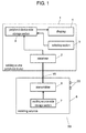
- Fig. 1 shows a schematic view of welding device 50 in accordance with the first exemplary embodiment.
- Welding device 50 has welding-source peripheral device 1 (hereinafter, peripheral device 1) and welding source 6.
- Peripheral device 1 includes receiver 2, peripheral-device-side storage section 3 (hereinafter, storage section 3), display 4 and selecting section 5.
- Receiver 2 receives welding condition items transmitted from welding source 6.
- the welding condition item is a welding method, a diameter of a welding wire, welding material of the welding wire or a welding object, wire extension of the welding wire, availability of pulse welding, or the like.
- Storage section 3 stores welding condition items received by receiver 2.
- Display 4 displays the welding condition items stored in storage section 3.
- welding source 6 includes welding-source-side storage section 7 (hereinafter, storage section 7) and transmitter 8.
- Storage section 7 stores welding condition items workable on welding source 6.
- Transmitter 8 transmits the welding condition items stored in storage section 7 to peripheral device 1.
- Receiver 2 communicates with transmitter 8 via communication path 15.
- peripheral device 1 may be a robot controller for controlling a manipulator that holds a welding torch (not shown).
- Welding device 6 further includes welding output section 20 for feeding power between a welding electrode (not shown) and a welding object (also not shown).
- Welding source 6 is connected to peripheral device 1 via communication path 15.
- Transmitter 8 transmits all of welding condition items stored in storage section 7 to receiver 2.
- Storage section 3 of peripheral device 1 stores the welding condition items received by receiver 2.
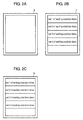
- FIG. 2A shows the state of storage section 3 with no data on welding condition items.
- Fig. 2B shows a storage area of storage section 7; for example, four sets (set 1 through set 4) of welding condition items are stored in storage section 7.
- Each set of welding condition items is formed of a combination of welding condition items. All the sets (i.e., set 1 through set 4 of welding condition items) stored in storage section 7 are transmitted to storage section 3 via transmitter 8, communication path 15 and receiver 2.
- each set of welding condition items includes the welding method, the diameter of the welding wire, the welding material of the welding wire or the welding object, the wire extension of the welding wire, the availability of pulse welding or the like.
- Display 4 displays the welding condition items stored in storage section 3. Selecting section 5 selects a proper item from the welding condition items stored in storage section 3 and carries out setting of welding conditions.
- Various communication methods such as a serial communication method and a parallel communication method, can be employed for transmitting/receiving the welding condition items via communication path 15.
- Display 4 and selecting section 5 may be formed into an integral component as a display/selecting section (not shown). In this case, the setting of welding condition items may be directly carried out on the welding condition items shown in the display/selecting section.
- welding condition items of welding source 6 are transmitted, as a set of welding condition items, to peripheral device 1 and stored in peripheral device 1. Even when welding source 6 has welding condition items changed or newly added with increase in performance, all the welding condition items of welding source 6 are transmitted to peripheral device 1 and stored there.
- peripheral device 1 accepts welding source 6-even if added or changed welding condition items are included therein-with no inconveniency as is seen in conventional cases; a repair people has to go to the location of the peripheral device to update the data on welding condition items in the peripheral device. This allows welding source 6 to be easily replaced with a different or an advanced model in production lines.
- the welding condition items includes the welding method, the diameter of the welding wire, the welding material of the welding wire or the welding object, the wire extension of the welding wire, the availability of pulse welding or the like.
- the welding condition items there are no limitations in the welding condition items; they can be flexibly determined as necessary.
- Each item of welding condition items serves as a key item for peripheral device 1 to acquire necessary information from a data table of unified voltage values in welding source 6. According to the selection of welding condition items in peripheral device 1, welding source 6 may transmit data necessary for welding to peripheral device 1.
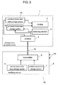
- Fig. 3 is a schematic view of welding device 50 in accordance with the second exemplary embodiment.
- Welding source 50 of the second embodiment differs from the structure of the first embodiment, as shown in Fig. 3 , in that welding source 6 has welding-source-name storage section 9 (hereinafter, storage section 9).
- peripheral device 1 has welding-source-name storage section 10 (hereinafter, storage section 10).
- Storage section 9 stores a model name of welding source 6.
- Storage section 10 stores the model name transmitted from welding source 6.
- Welding source 6 is connected to peripheral device 1 via communication path 15.
- transmitter 8 transmits the model name of welding source 6 stored in storage section 9 to receiver 2.
- Storage section 10 of peripheral device 1 stores the model name received by receiver 2.
- transmitter 8 transmits all the welding condition items stored in storage section 7 to receiver 2.
- Storage section 3 of peripheral device 1 stores the welding condition items received by receiver 2.
- display 4 displays the unique model name of welding source 6 stored in storage section 10 and the welding condition items stored in storage section 3.
- the model name of welding source 6 is transmitted to peripheral device 1 and is displayed on the display section of peripheral device 1, by which the operator easily recognizes the model name of welding source 6 connected to peripheral device 1.
- Storage section 9 and storage section 7 may be formed into an identical storage section; similarly, storage section 10 and storage section 3 may be formed into an identical storage section.
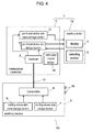
- Fig. 4 is a schematic view of welding device 50 in accordance with the third exemplary embodiment.
- Welding device 50 of the third embodiment differs from the structure in the second embodiment, as shown in Fig. 4 , in that peripheral device 1 has manipulator controller 11 (hereinafter, controller 11) and teaching device 12 connected to controller 11.
- Teaching device 12 has display 4 and selecting section 5.
- Controller 11 controls a manipulator (not shown) that holds a welding torch (not shown).
- Controller 11 has manipulator control section 13.
- welding condition items held in welding source 6 are transmitted to controller 11.
- controller 11 of peripheral device 1 accepts welding source 6, even if added or changed welding conditions are included therein, and becomes ready for welding. This allows welding source 6 to be easily replaced with a different or an advanced model in production lines.
- Display 4 of teaching device 12 displays the unique model name of welding source 6 stored in storage section 10 and the welding condition items stored in storage section 3. Selecting section 5 of teaching device 12 appropriately selects welding conditions of the welding condition items which are stored in storage section 10 and shown on display 4.
- Teaching device 12 displays the model name of welding source 6, selects appropriate welding conditions shown on the display section and teaches the manipulator by oneself. This saves time and effort of the operator in entry operations of welding conditions.
- Controller 11 and teaching device 12 of the third embodiment are applicable to peripheral device 1 of the first exemplary embodiment.
- the peripheral device accepts various types of welding source, even if the welding source contains welding conditions changed or newly added with increase in performance. This allows the welding source to be easily replaced with a different or an advanced model in production lines.
- the present invention is suitable for a welding device having communications capabilities.
Abstract
Description
- The present invention relates to a welding device having a welding source and a welding-source peripheral device.
- A conventional welding device has a welding source and a welding-source peripheral device. The welding source transmits to the peripheral device a huge data table having a unified voltage value and a device-identification signal for identifying the type of the welding source. Such a welding device is introduced in patent reference 1 (see Japanese Unexamined Patent Application Publication No.
2000-334566 - An example of conventional welding devices will be described with reference to
Fig. 5 andFig. 6 . As shown inFig. 5 ,welding device 100 haswelding source 106 and welding-source peripheral device 101 (hereinafter, peripheral device 101).Peripheral device 101 communicates withwelding source 106 viacommunication path 115.Peripheral device 101 has device-identification signal input section 113 (hereinafter, input section 113); on the other hand,welding source 106 has device-identification signal output section 114 (hereinafter, output section 114). -
Input section 113 has a plurality of data sets of a device-identification code and welding condition items, as shown inFig. 6 . The device-identification code corresponds to the device-identification signal. The welding condition items include the following items: a welding method; a welding material; a diameter of a welding wire; a welding pulse; or wire extension of the welding wire.Welding source 106 transmits to peripheral device 101 a device-identification code fed fromoutput section 114. Receiving the device-identification code fromwelding source 106,peripheral device 101 checks the code against the device-identification codes stored ininput section 113 and determines welding condition items ofwelding source 106 connected toperipheral device 101. Besides, the determined welding condition items are shown on a display (not shown), which allows the operator to set welding conditions. - Specifically, as shown in
Fig. 6 ,input section 113 stores device-identification codes 1 through 4 and welding condition items associated with each identification code. For example, when device-identification code 3 is received fromwelding source 106,peripheral device 101 determines the welding conditions associated with device-identification code 3. - In
welding device 100 havingwelding source 106 andperipheral device 101, sinceinput section 113 stores in advance welding condition items associated with the device-identification codes, suitable welding condition items are selected according to a device-identification code fed fromwelding source 106. Ifwelding source 106 whose device-identification code is not stored ininput section 113 is connected toperipheral device 101, an unknown device-identification code is fed intoperipheral device 101 fromwelding source 106;peripheral device 101 has no data on the device-identification code and accordingly, no welding condition items associated with the code. In this case, welding condition items of the unknown welding source cannot be determined, so that a welding is not carried out. For example, whenwelding source 106 having device-identification code 5 is connected toperipheral device 101 inFig. 6 ,peripheral device 101 has no data on device-identification code 5 and accordingly, no welding condition items associated with the code. Therefore, welding condition items suitable forwelding source 106 cannot be determined, so that the welding with the use ofwelding source 106 is not carried out. - In
conventional welding device 100, each time the aforementioned problem occurs, a repair people has to go to the location ofperipheral device 101 to update the data ininput section 113; a new device-identification code and welding condition items associated with the new code are additionally stored inperipheral device 101. - Unless the data stored in
input section 113 is not updated, new type ofwelding source 106 or new-function-addedwelding source 106 cannot be employed for welding. Production lines have a difficulty in introducingwelding source 106 of a new type or with new welding conditions added. - Patent reference 1: Japanese Unexamined Patent Application Publication No.
2000-334566 - The present invention provides a welding device in which a welding source outputs a welding condition item workable on the welding source to a welding-source peripheral device so that the peripheral device carries out setting of the welding condition item.
- A welding device of the present invention has a welding source and a welding-source peripheral device. The welding source includes a welding-source-side storage section for storing a welding condition item and a transmitter for transmitting the welding condition item stored in the welding-source-side storage section to the welding-source peripheral device. On the other hand, the welding-source peripheral device includes a receiver for receiving the welding condition item fed from the transmitter; a peripheral-device-side storage section for storing the welding condition item received by the receiver; a display for displaying the welding condition item stored in the peripheral-device-side storage section; and a selecting section for selecting the welding condition item shown on the display. Such structured welding-source peripheral device receives the welding condition item and carries out setting of the welding condition item suitable for the welding source, allowing the welding device to employ for various types of welding source.
- A welding device of the present invention has a welding source and a welding-source peripheral device connected to the welding source. The welding source includes a welding-source-name storage section for storing a model name of the welding source and a transmitter for transmitting the model name stored in the welding-source-name storage section. On the other hand, the welding-source peripheral device includes a receiver for receiving the model name fed from the transmitter; a welding-source-name storage section for storing the model name received by the receiver; and a display for displaying the model name stored in the welding-source-name storage section. Such structured the welding-source peripheral device receives a welding condition item and carries out setting of the welding condition item suitable for the welding source, allowing the welding device to employ for various types of welding source.
-
-
Fig. 1 is a schematic view of a welding device in accordance with a first exemplary embodiment of the present invention. -
Fig. 2A is a schematic view of data stored in a storage section of a welding-source peripheral device employed for the welding device ofFig. 1 . -
Fig. 2B is a schematic view of data stored in a storage section of a welding source employed for the welding device ofFig. 1 . -
Fig. 2C is a schematic view of data stored in the storage section of the welding-source peripheral device employed for the welding device ofFig. 1 . -
Fig. 3 is a schematic view of a welding device in accordance with a second exemplary embodiment of the present invention. -
Fig. 4 is a schematic view of a welding device in accordance with a third exemplary embodiment of the present invention. -
Fig. 5 is a schematic view of a conventional welding device. -
Fig. 6 is another schematic view of the conventional welding device. -
- 1
- welding-source peripheral device
- 2
- receiver
- 3
- peripheral-device-side storage section
- 4
- display
- 5
- selecting section
- 6
- welding source
- 7
- welding-source-side storage section
- 8
- transmitter
- 9
- welding-source-side name-storage section
- 10
- peripheral-device-side name-storage section
- 11
- manipulator controller
- 12
- teaching device
- 13
- manipulator control section
- 15
- communication path
- 20
- welding output section
- 50
- welding device
-
Fig. 1 shows a schematic view ofwelding device 50 in accordance with the first exemplary embodiment.Welding device 50, as shown inFig. 1 , has welding-source peripheral device 1 (hereinafter, peripheral device 1) andwelding source 6.Peripheral device 1 includesreceiver 2, peripheral-device-side storage section 3 (hereinafter, storage section 3),display 4 and selectingsection 5.Receiver 2 receives welding condition items transmitted from weldingsource 6. For example, the welding condition item is a welding method, a diameter of a welding wire, welding material of the welding wire or a welding object, wire extension of the welding wire, availability of pulse welding, or the like.Storage section 3 stores welding condition items received byreceiver 2.Display 4 displays the welding condition items stored instorage section 3. Selecting a proper item from the welding condition items stored instorage section 3, selectingsection 5 carries out setting of welding conditions. On the other hand, weldingsource 6 includes welding-source-side storage section 7 (hereinafter, storage section 7) andtransmitter 8.Storage section 7 stores welding condition items workable onwelding source 6.Transmitter 8 transmits the welding condition items stored instorage section 7 toperipheral device 1.Receiver 2 communicates withtransmitter 8 viacommunication path 15. - An example of
peripheral device 1 may be a robot controller for controlling a manipulator that holds a welding torch (not shown).Welding device 6 further includeswelding output section 20 for feeding power between a welding electrode (not shown) and a welding object (also not shown). - Here will be described the workings of
aforementioned welding device 50 havingwelding source 6 andperipheral device 1. - Welding
source 6 is connected toperipheral device 1 viacommunication path 15.Transmitter 8 transmits all of welding condition items stored instorage section 7 toreceiver 2.Storage section 3 ofperipheral device 1 stores the welding condition items received byreceiver 2. - Next will be described the storing process of welding condition items in
storage section 3, taking an example with reference toFigs. 2A through 2C . On startup ofperipheral device 1,storage section 3 clears a storage area.Fig. 2A shows the state ofstorage section 3 with no data on welding condition items. On the other hand,Fig. 2B shows a storage area ofstorage section 7; for example, four sets (set 1 through set 4) of welding condition items are stored instorage section 7. Each set of welding condition items is formed of a combination of welding condition items. All the sets (i.e., set 1 throughset 4 of welding condition items) stored instorage section 7 are transmitted tostorage section 3 viatransmitter 8,communication path 15 andreceiver 2. As a result of the transmission above,storage section 3 has set 1 throughset 4 of welding condition items, as shown inFig. 2C . For example, each set of welding condition items includes the welding method, the diameter of the welding wire, the welding material of the welding wire or the welding object, the wire extension of the welding wire, the availability of pulse welding or the like. -
Display 4 displays the welding condition items stored instorage section 3. Selectingsection 5 selects a proper item from the welding condition items stored instorage section 3 and carries out setting of welding conditions. - Various communication methods, such as a serial communication method and a parallel communication method, can be employed for transmitting/receiving the welding condition items via
communication path 15. -
Display 4 and selectingsection 5 may be formed into an integral component as a display/selecting section (not shown). In this case, the setting of welding condition items may be directly carried out on the welding condition items shown in the display/selecting section. - According to welding
device 50 of the embodiment, as described above, welding condition items ofwelding source 6 are transmitted, as a set of welding condition items, toperipheral device 1 and stored inperipheral device 1. Even when weldingsource 6 has welding condition items changed or newly added with increase in performance, all the welding condition items ofwelding source 6 are transmitted toperipheral device 1 and stored there. With the structure above,peripheral device 1 accepts welding source 6-even if added or changed welding condition items are included therein-with no inconveniency as is seen in conventional cases; a repair people has to go to the location of the peripheral device to update the data on welding condition items in the peripheral device. This allowswelding source 6 to be easily replaced with a different or an advanced model in production lines. - As discussed above, the welding condition items includes the welding method, the diameter of the welding wire, the welding material of the welding wire or the welding object, the wire extension of the welding wire, the availability of pulse welding or the like. However, there are no limitations in the welding condition items; they can be flexibly determined as necessary. Each item of welding condition items serves as a key item for
peripheral device 1 to acquire necessary information from a data table of unified voltage values inwelding source 6. According to the selection of welding condition items inperipheral device 1,welding source 6 may transmit data necessary for welding toperipheral device 1. -
Fig. 3 is a schematic view ofwelding device 50 in accordance with the second exemplary embodiment. In the structure of the second embodiment, like parts have similar reference numerals as in that of the first exemplary embodiment and the explanation thereof will be omitted. Weldingsource 50 of the second embodiment differs from the structure of the first embodiment, as shown inFig. 3 , in thatwelding source 6 has welding-source-name storage section 9 (hereinafter, storage section 9). Furthermore,peripheral device 1 has welding-source-name storage section 10 (hereinafter, storage section 10).Storage section 9 stores a model name ofwelding source 6.Storage section 10 stores the model name transmitted from weldingsource 6. - Here will be described the workings of
aforementioned welding device 50 havingwelding source 6 andperipheral device 1. - Welding
source 6 is connected toperipheral device 1 viacommunication path 15. First,transmitter 8 transmits the model name ofwelding source 6 stored instorage section 9 toreceiver 2.Storage section 10 ofperipheral device 1 stores the model name received byreceiver 2. - Next,
transmitter 8 transmits all the welding condition items stored instorage section 7 toreceiver 2.Storage section 3 ofperipheral device 1 stores the welding condition items received byreceiver 2. - After that,
display 4 displays the unique model name ofwelding source 6 stored instorage section 10 and the welding condition items stored instorage section 3. - As described above, the model name of
welding source 6 is transmitted toperipheral device 1 and is displayed on the display section ofperipheral device 1, by which the operator easily recognizes the model name ofwelding source 6 connected toperipheral device 1. -
Storage section 9 andstorage section 7 may be formed into an identical storage section; similarly,storage section 10 andstorage section 3 may be formed into an identical storage section. -
Fig. 4 is a schematic view ofwelding device 50 in accordance with the third exemplary embodiment. In the structure of the third embodiment, like parts have similar reference numerals as in that of the second exemplary embodiment and the explanation thereof will be omitted.Welding device 50 of the third embodiment differs from the structure in the second embodiment, as shown inFig. 4 , in thatperipheral device 1 has manipulator controller 11 (hereinafter, controller 11) andteaching device 12 connected tocontroller 11.Teaching device 12 hasdisplay 4 and selectingsection 5.Controller 11 controls a manipulator (not shown) that holds a welding torch (not shown).Controller 11 hasmanipulator control section 13. - According to welding
device 50 of the third embodiment, the welding condition items held inwelding source 6 are transmitted tocontroller 11. With the structure above,controller 11 ofperipheral device 1 acceptswelding source 6, even if added or changed welding conditions are included therein, and becomes ready for welding. This allowswelding source 6 to be easily replaced with a different or an advanced model in production lines. -
Display 4 ofteaching device 12 displays the unique model name ofwelding source 6 stored instorage section 10 and the welding condition items stored instorage section 3. Selectingsection 5 ofteaching device 12 appropriately selects welding conditions of the welding condition items which are stored instorage section 10 and shown ondisplay 4. -
Teaching device 12 displays the model name ofwelding source 6, selects appropriate welding conditions shown on the display section and teaches the manipulator by oneself. This saves time and effort of the operator in entry operations of welding conditions. -
Controller 11 andteaching device 12 of the third embodiment are applicable toperipheral device 1 of the first exemplary embodiment. - According to the welding device having a welding source and a welding-source peripheral device of the present invention, the peripheral device accepts various types of welding source, even if the welding source contains welding conditions changed or newly added with increase in performance. This allows the welding source to be easily replaced with a different or an advanced model in production lines. The present invention is suitable for a welding device having communications capabilities.
Claims (7)
- A welding device comprising:a welding source including:a welding-source-side storage section for storing a welding condition item; anda transmitter for transmitting the welding condition item stored in the welding-source-side storage section; anda welding-source peripheral device including:a receiver for receiving the welding condition item transmitted from the transmitter;a peripheral-device-side storage section for storing the welding condition item received by the receiver;a display for displaying the welding condition item stored in the peripheral-device-side storage section; anda selecting section for selecting the welding condition item shown on the display.
- The welding device of claim 1,
wherein the welding condition item includes at least one of a welding method, a diameter of a welding wire, a welding material of the welding wire, a material of a welding object, wire extension of the welding wire, and availability of pulse welding. - The welding device of claim 1 or claim 2,
wherein the welding-source peripheral device has
a manipulator controller for controlling a manipulator that holds a welding torch; and
a teaching device connected to the manipulator controller, and the display is disposed on the teaching device. - The welding device of claim 1 or claim 2,
wherein the welding source transmits all the welding condition items stored in the welding-source-side storage section to the welding-source peripheral device. - The welding device of claim 4,
wherein the welding-source peripheral device has
a manipulator controller for controlling a manipulator that holds a welding torch; and
a teaching device connected to the manipulator controller, and the display is disposed on the teaching device. - A welding device comprising:a welding source including:a welding-source-side name-storage section for storing a model name of the welding source; anda transmitter for transmitting the model name stored in the welding-source-side name-storage section; anda welding-source peripheral device connected to the welding source, the welding-source peripheral device including:a receiver for receiving the model name transmitted from the transmitter;a peripheral-device-side name-storage section for storing the model name received by the receiver; anda display for displaying the model name stored in the peripheral-device-side name-storage section.
- The welding device of claim 6,
wherein the welding-source peripheral device has
a manipulator controller for controlling a manipulator that holds a welding torch; and
a teaching device connected to the manipulator controller, and the display is disposed on the teaching device.
Applications Claiming Priority (2)
| Application Number | Priority Date | Filing Date | Title |
|---|---|---|---|
| JP2007070168 | 2007-03-19 | ||
| PCT/JP2007/073374 WO2008114478A1 (en) | 2007-03-19 | 2007-12-04 | Welding apparatus |
Publications (2)
| Publication Number | Publication Date |
|---|---|
| EP2000246A1 true EP2000246A1 (en) | 2008-12-10 |
| EP2000246A4 EP2000246A4 (en) | 2009-10-28 |
Family
ID=39765597
Family Applications (1)
| Application Number | Title | Priority Date | Filing Date |
|---|---|---|---|
| EP07850024A Withdrawn EP2000246A4 (en) | 2007-03-19 | 2007-12-04 | Welding apparatus |
Country Status (5)
| Country | Link |
|---|---|
| US (1) | US20090057286A1 (en) |
| EP (1) | EP2000246A4 (en) |
| JP (1) | JPWO2008114478A1 (en) |
| CN (1) | CN101415516A (en) |
| WO (1) | WO2008114478A1 (en) |
Cited By (1)
| Publication number | Priority date | Publication date | Assignee | Title |
|---|---|---|---|---|
| WO2012135479A1 (en) * | 2011-03-29 | 2012-10-04 | Illinois Tool Works Inc. | Welding electrode stickout monitoring and control |
Families Citing this family (99)
| Publication number | Priority date | Publication date | Assignee | Title |
|---|---|---|---|---|
| US9104195B2 (en) | 2006-12-20 | 2015-08-11 | Lincoln Global, Inc. | Welding job sequencer |
| US10994358B2 (en) | 2006-12-20 | 2021-05-04 | Lincoln Global, Inc. | System and method for creating or modifying a welding sequence based on non-real world weld data |
| US9937577B2 (en) | 2006-12-20 | 2018-04-10 | Lincoln Global, Inc. | System for a welding sequencer |
| US9352411B2 (en) | 2008-05-28 | 2016-05-31 | Illinois Tool Works Inc. | Welding training system |
| US8911237B2 (en) | 2008-08-21 | 2014-12-16 | Lincoln Global, Inc. | Virtual reality pipe welding simulator and setup |
| US9196169B2 (en) | 2008-08-21 | 2015-11-24 | Lincoln Global, Inc. | Importing and analyzing external data using a virtual reality welding system |
| US9280913B2 (en) | 2009-07-10 | 2016-03-08 | Lincoln Global, Inc. | Systems and methods providing enhanced education and training in a virtual reality environment |
| US8851896B2 (en) | 2008-08-21 | 2014-10-07 | Lincoln Global, Inc. | Virtual reality GTAW and pipe welding simulator and setup |
| US8884177B2 (en) | 2009-11-13 | 2014-11-11 | Lincoln Global, Inc. | Systems, methods, and apparatuses for monitoring weld quality |
| US9318026B2 (en) | 2008-08-21 | 2016-04-19 | Lincoln Global, Inc. | Systems and methods providing an enhanced user experience in a real-time simulated virtual reality welding environment |
| US9330575B2 (en) | 2008-08-21 | 2016-05-03 | Lincoln Global, Inc. | Tablet-based welding simulator |
| US8834168B2 (en) | 2008-08-21 | 2014-09-16 | Lincoln Global, Inc. | System and method providing combined virtual reality arc welding and three-dimensional (3D) viewing |
| US8747116B2 (en) | 2008-08-21 | 2014-06-10 | Lincoln Global, Inc. | System and method providing arc welding training in a real-time simulated virtual reality environment using real-time weld puddle feedback |
| US9483959B2 (en) | 2008-08-21 | 2016-11-01 | Lincoln Global, Inc. | Welding simulator |
| US8915740B2 (en) | 2008-08-21 | 2014-12-23 | Lincoln Global, Inc. | Virtual reality pipe welding simulator |
| US8657605B2 (en) * | 2009-07-10 | 2014-02-25 | Lincoln Global, Inc. | Virtual testing and inspection of a virtual weldment |
| US8274013B2 (en) | 2009-03-09 | 2012-09-25 | Lincoln Global, Inc. | System for tracking and analyzing welding activity |
| JP5349100B2 (en) * | 2009-03-23 | 2013-11-20 | 株式会社ダイヘン | Welding power supply |
| US9221117B2 (en) | 2009-07-08 | 2015-12-29 | Lincoln Global, Inc. | System for characterizing manual welding operations |
| US9773429B2 (en) | 2009-07-08 | 2017-09-26 | Lincoln Global, Inc. | System and method for manual welder training |
| US20110006047A1 (en) * | 2009-07-08 | 2011-01-13 | Victor Matthew Penrod | Method and system for monitoring and characterizing the creation of a manual weld |
| US9230449B2 (en) * | 2009-07-08 | 2016-01-05 | Lincoln Global, Inc. | Welding training system |
| US10748447B2 (en) | 2013-05-24 | 2020-08-18 | Lincoln Global, Inc. | Systems and methods providing a computerized eyewear device to aid in welding |
| US9011154B2 (en) | 2009-07-10 | 2015-04-21 | Lincoln Global, Inc. | Virtual welding system |
| US8569655B2 (en) | 2009-10-13 | 2013-10-29 | Lincoln Global, Inc. | Welding helmet with integral user interface |
| US9468988B2 (en) | 2009-11-13 | 2016-10-18 | Lincoln Global, Inc. | Systems, methods, and apparatuses for monitoring weld quality |
| US8569646B2 (en) | 2009-11-13 | 2013-10-29 | Lincoln Global, Inc. | Systems, methods, and apparatuses for monitoring weld quality |
| US9993891B2 (en) | 2010-07-14 | 2018-06-12 | Illinois Tool Works Inc. | Welding parameter control via welder motion or position monitoring |
| US9782852B2 (en) | 2010-07-16 | 2017-10-10 | Hypertherm, Inc. | Plasma torch with LCD display with settings adjustment and fault diagnosis |
| US10486260B2 (en) * | 2012-04-04 | 2019-11-26 | Hypertherm, Inc. | Systems, methods, and devices for transmitting information to thermal processing systems |
| US10455682B2 (en) * | 2012-04-04 | 2019-10-22 | Hypertherm, Inc. | Optimization and control of material processing using a thermal processing torch |
| US9101994B2 (en) | 2011-08-10 | 2015-08-11 | Illinois Tool Works Inc. | System and device for welding training |
| IN2014CN02457A (en) * | 2011-10-06 | 2015-08-07 | Panasonic Corp | |
| US9573215B2 (en) | 2012-02-10 | 2017-02-21 | Illinois Tool Works Inc. | Sound-based weld travel speed sensing system and method |
| US11783138B2 (en) * | 2012-04-04 | 2023-10-10 | Hypertherm, Inc. | Configuring signal devices in thermal processing systems |
| US9395715B2 (en) | 2012-04-04 | 2016-07-19 | Hypertherm, Inc. | Identifying components in a material processing system |
| US20150332071A1 (en) * | 2012-04-04 | 2015-11-19 | Hypertherm, Inc. | Configuring Signal Devices in Thermal Processing Systems |
| US9672460B2 (en) | 2012-04-04 | 2017-06-06 | Hypertherm, Inc. | Configuring signal devices in thermal processing systems |
| US9737954B2 (en) | 2012-04-04 | 2017-08-22 | Hypertherm, Inc. | Automatically sensing consumable components in thermal processing systems |
| ES2438440B1 (en) * | 2012-06-13 | 2014-07-30 | Seabery Soluciones, S.L. | ADVANCED DEVICE FOR SIMULATION-BASED WELDING TRAINING WITH INCREASED REALITY AND REMOTE UPDATE |
| US20160093233A1 (en) | 2012-07-06 | 2016-03-31 | Lincoln Global, Inc. | System for characterizing manual welding operations on pipe and other curved structures |
| US9767712B2 (en) | 2012-07-10 | 2017-09-19 | Lincoln Global, Inc. | Virtual reality pipe welding simulator and setup |
| US9368045B2 (en) | 2012-11-09 | 2016-06-14 | Illinois Tool Works Inc. | System and device for welding training |
| US9583014B2 (en) | 2012-11-09 | 2017-02-28 | Illinois Tool Works Inc. | System and device for welding training |
| US9583023B2 (en) | 2013-03-15 | 2017-02-28 | Illinois Tool Works Inc. | Welding torch for a welding training system |
| US9672757B2 (en) | 2013-03-15 | 2017-06-06 | Illinois Tool Works Inc. | Multi-mode software and method for a welding training system |
| US9728103B2 (en) | 2013-03-15 | 2017-08-08 | Illinois Tool Works Inc. | Data storage and analysis for a welding training system |
| US9666100B2 (en) | 2013-03-15 | 2017-05-30 | Illinois Tool Works Inc. | Calibration devices for a welding training system |
| US9713852B2 (en) | 2013-03-15 | 2017-07-25 | Illinois Tool Works Inc. | Welding training systems and devices |
| US10930174B2 (en) | 2013-05-24 | 2021-02-23 | Lincoln Global, Inc. | Systems and methods providing a computerized eyewear device to aid in welding |
| US11090753B2 (en) | 2013-06-21 | 2021-08-17 | Illinois Tool Works Inc. | System and method for determining weld travel speed |
| US20150072323A1 (en) | 2013-09-11 | 2015-03-12 | Lincoln Global, Inc. | Learning management system for a real-time simulated virtual reality welding training environment |
| US9643273B2 (en) | 2013-10-14 | 2017-05-09 | Hypertherm, Inc. | Systems and methods for configuring a cutting or welding delivery device |
| US10083627B2 (en) | 2013-11-05 | 2018-09-25 | Lincoln Global, Inc. | Virtual reality and real welding training system and method |
| US10056010B2 (en) | 2013-12-03 | 2018-08-21 | Illinois Tool Works Inc. | Systems and methods for a weld training system |
| US10105782B2 (en) | 2014-01-07 | 2018-10-23 | Illinois Tool Works Inc. | Feedback from a welding torch of a welding system |
| US9724788B2 (en) | 2014-01-07 | 2017-08-08 | Illinois Tool Works Inc. | Electrical assemblies for a welding system |
| US10170019B2 (en) | 2014-01-07 | 2019-01-01 | Illinois Tool Works Inc. | Feedback from a welding torch of a welding system |
| US9589481B2 (en) | 2014-01-07 | 2017-03-07 | Illinois Tool Works Inc. | Welding software for detection and control of devices and for analysis of data |
| US9757819B2 (en) | 2014-01-07 | 2017-09-12 | Illinois Tool Works Inc. | Calibration tool and method for a welding system |
| US9751149B2 (en) | 2014-01-07 | 2017-09-05 | Illinois Tool Works Inc. | Welding stand for a welding system |
| US9836987B2 (en) | 2014-02-14 | 2017-12-05 | Lincoln Global, Inc. | Virtual reality pipe welding simulator and setup |
| US10786924B2 (en) | 2014-03-07 | 2020-09-29 | Hypertherm, Inc. | Waterjet cutting head temperature sensor |
| US9993934B2 (en) | 2014-03-07 | 2018-06-12 | Hyperthem, Inc. | Liquid pressurization pump and systems with data storage |
| US20150269603A1 (en) | 2014-03-19 | 2015-09-24 | Hypertherm, Inc. | Methods for Developing Customer Loyalty Programs and Related Systems and Devices |
| CN106233358A (en) | 2014-06-02 | 2016-12-14 | 林肯环球股份有限公司 | System and method for artificial welders training |
| US10665128B2 (en) | 2014-06-27 | 2020-05-26 | Illinois Tool Works Inc. | System and method of monitoring welding information |
| US10307853B2 (en) | 2014-06-27 | 2019-06-04 | Illinois Tool Works Inc. | System and method for managing welding data |
| US9862049B2 (en) | 2014-06-27 | 2018-01-09 | Illinois Tool Works Inc. | System and method of welding system operator identification |
| US9937578B2 (en) | 2014-06-27 | 2018-04-10 | Illinois Tool Works Inc. | System and method for remote welding training |
| US9724787B2 (en) | 2014-08-07 | 2017-08-08 | Illinois Tool Works Inc. | System and method of monitoring a welding environment |
| US11014183B2 (en) | 2014-08-07 | 2021-05-25 | Illinois Tool Works Inc. | System and method of marking a welding workpiece |
| US9875665B2 (en) | 2014-08-18 | 2018-01-23 | Illinois Tool Works Inc. | Weld training system and method |
| US10987762B2 (en) | 2014-09-30 | 2021-04-27 | Illinois Tool Works Inc. | Armband based systems and methods for controlling welding equipment using gestures and like motions |
| US10201868B2 (en) * | 2014-09-30 | 2019-02-12 | Illinois Tool Works Inc. | Systems and methods for gesture control of a welding system |
| US11247289B2 (en) | 2014-10-16 | 2022-02-15 | Illinois Tool Works Inc. | Remote power supply parameter adjustment |
| US10239147B2 (en) | 2014-10-16 | 2019-03-26 | Illinois Tool Works Inc. | Sensor-based power controls for a welding system |
| US10373304B2 (en) | 2014-11-05 | 2019-08-06 | Illinois Tool Works Inc. | System and method of arranging welding device markers |
| US10490098B2 (en) | 2014-11-05 | 2019-11-26 | Illinois Tool Works Inc. | System and method of recording multi-run data |
| US10417934B2 (en) | 2014-11-05 | 2019-09-17 | Illinois Tool Works Inc. | System and method of reviewing weld data |
| US10210773B2 (en) | 2014-11-05 | 2019-02-19 | Illinois Tool Works Inc. | System and method for welding torch display |
| US10204406B2 (en) | 2014-11-05 | 2019-02-12 | Illinois Tool Works Inc. | System and method of controlling welding system camera exposure and marker illumination |
| US10402959B2 (en) | 2014-11-05 | 2019-09-03 | Illinois Tool Works Inc. | System and method of active torch marker control |
| US10427239B2 (en) | 2015-04-02 | 2019-10-01 | Illinois Tool Works Inc. | Systems and methods for tracking weld training arc parameters |
| US10657839B2 (en) | 2015-08-12 | 2020-05-19 | Illinois Tool Works Inc. | Stick welding electrode holders with real-time feedback features |
| US10373517B2 (en) | 2015-08-12 | 2019-08-06 | Illinois Tool Works Inc. | Simulation stick welding electrode holder systems and methods |
| US10438505B2 (en) | 2015-08-12 | 2019-10-08 | Illinois Tool Works | Welding training system interface |
| US10593230B2 (en) | 2015-08-12 | 2020-03-17 | Illinois Tool Works Inc. | Stick welding electrode holder systems and methods |
| EP3319066A1 (en) | 2016-11-04 | 2018-05-09 | Lincoln Global, Inc. | Magnetic frequency selection for electromagnetic position tracking |
| US20180130226A1 (en) | 2016-11-07 | 2018-05-10 | Lincoln Global, Inc. | System and method for calibrating a welding trainer |
| US10913125B2 (en) | 2016-11-07 | 2021-02-09 | Lincoln Global, Inc. | Welding system providing visual and audio cues to a welding helmet with a display |
| US10997872B2 (en) | 2017-06-01 | 2021-05-04 | Lincoln Global, Inc. | Spring-loaded tip assembly to support simulated shielded metal arc welding |
| US10625359B2 (en) | 2018-04-06 | 2020-04-21 | The Esab Group Inc. | Automatic identification of components for welding and cutting torches |
| US11267069B2 (en) | 2018-04-06 | 2022-03-08 | The Esab Group Inc. | Recognition of components for welding and cutting torches |
| US11475792B2 (en) | 2018-04-19 | 2022-10-18 | Lincoln Global, Inc. | Welding simulator with dual-user configuration |
| US11557223B2 (en) | 2018-04-19 | 2023-01-17 | Lincoln Global, Inc. | Modular and reconfigurable chassis for simulated welding training |
| US11776423B2 (en) | 2019-07-22 | 2023-10-03 | Illinois Tool Works Inc. | Connection boxes for gas tungsten arc welding training systems |
| US11288978B2 (en) | 2019-07-22 | 2022-03-29 | Illinois Tool Works Inc. | Gas tungsten arc welding training systems |
| US11457483B2 (en) * | 2020-03-30 | 2022-09-27 | Citrix Systems, Inc. | Managing connections between a user device and peripheral devices |
Citations (5)
| Publication number | Priority date | Publication date | Assignee | Title |
|---|---|---|---|---|
| EP1057567A2 (en) * | 1999-05-25 | 2000-12-06 | Matsushita Electric Industrial Co., Ltd. | ARC welding power supply, peripheral device for ARC welding, and ARC welding apparatus |
| EP1136168A2 (en) * | 2000-03-22 | 2001-09-26 | Matsushita Electric Industrial Co., Ltd. | Arc welding apparatus |
| EP1380377A2 (en) * | 2002-07-09 | 2004-01-14 | Lincoln Global, Inc. | Apparatus, system and method to facilitate reconfigurable welding power supply |
| US20040045945A1 (en) * | 2001-09-28 | 2004-03-11 | Shigeru Shimogama | Arc welder |
| JP2005284508A (en) * | 2004-03-29 | 2005-10-13 | Matsushita Electric Ind Co Ltd | Welding robot system |
Family Cites Families (6)
| Publication number | Priority date | Publication date | Assignee | Title |
|---|---|---|---|---|
| JP3090565B2 (en) * | 1993-08-27 | 2000-09-25 | 株式会社三協精機製作所 | Operating systems for industrial machines |
| JPH08286725A (en) * | 1995-04-13 | 1996-11-01 | Miyachi Technos Corp | Resistance welding or laser machining terminal unit, resistance welding or laser machining controller, and terminal unit operating method |
| JP3824555B2 (en) * | 2002-05-20 | 2006-09-20 | 株式会社電元社製作所 | Welding parameter setting method for resistance welding machine control device |
| CA2428981C (en) * | 2002-05-20 | 2007-12-04 | Dengensha Manufacturing Company Limited | Welding parameters setting method for a resistance welder controll apparatus |
| JP3670633B2 (en) * | 2002-08-21 | 2005-07-13 | ファナック株式会社 | Wire electrical discharge machine |
| JP4796881B2 (en) * | 2006-03-31 | 2011-10-19 | 株式会社ダイヘン | Welding robot system |
-
2007
- 2007-12-04 WO PCT/JP2007/073374 patent/WO2008114478A1/en active Application Filing
- 2007-12-04 CN CNA2007800110654A patent/CN101415516A/en active Pending
- 2007-12-04 JP JP2008520163A patent/JPWO2008114478A1/en active Pending
- 2007-12-04 US US12/160,362 patent/US20090057286A1/en not_active Abandoned
- 2007-12-04 EP EP07850024A patent/EP2000246A4/en not_active Withdrawn
Patent Citations (5)
| Publication number | Priority date | Publication date | Assignee | Title |
|---|---|---|---|---|
| EP1057567A2 (en) * | 1999-05-25 | 2000-12-06 | Matsushita Electric Industrial Co., Ltd. | ARC welding power supply, peripheral device for ARC welding, and ARC welding apparatus |
| EP1136168A2 (en) * | 2000-03-22 | 2001-09-26 | Matsushita Electric Industrial Co., Ltd. | Arc welding apparatus |
| US20040045945A1 (en) * | 2001-09-28 | 2004-03-11 | Shigeru Shimogama | Arc welder |
| EP1380377A2 (en) * | 2002-07-09 | 2004-01-14 | Lincoln Global, Inc. | Apparatus, system and method to facilitate reconfigurable welding power supply |
| JP2005284508A (en) * | 2004-03-29 | 2005-10-13 | Matsushita Electric Ind Co Ltd | Welding robot system |
Non-Patent Citations (1)
| Title |
|---|
| See also references of WO2008114478A1 * |
Cited By (1)
| Publication number | Priority date | Publication date | Assignee | Title |
|---|---|---|---|---|
| WO2012135479A1 (en) * | 2011-03-29 | 2012-10-04 | Illinois Tool Works Inc. | Welding electrode stickout monitoring and control |
Also Published As
| Publication number | Publication date |
|---|---|
| CN101415516A (en) | 2009-04-22 |
| JPWO2008114478A1 (en) | 2010-07-01 |
| US20090057286A1 (en) | 2009-03-05 |
| WO2008114478A1 (en) | 2008-09-25 |
| EP2000246A4 (en) | 2009-10-28 |
Similar Documents
| Publication | Publication Date | Title |
|---|---|---|
| EP2000246A1 (en) | Welding apparatus | |
| US7043310B2 (en) | Device and process for operation of automation components | |
| DE102010025781B4 (en) | Portable safety input device for a robot controller | |
| US7206834B1 (en) | Industrial controller for machine tools, robots and/or production machines | |
| US10491290B2 (en) | Controller in wireless communication with operation panel, wireless module, and wireless repeater | |
| US10416658B2 (en) | Operation management system | |
| CN106919138B (en) | Control numerical control device, method and the storage medium of lathe | |
| KR20190075745A (en) | Monitering method and devise of pull cord switch, and belt conveyor comprising the monitering devise of pull cord switch | |
| JP5241969B2 (en) | Display device and method for confirming operation of display device | |
| TWI498844B (en) | Engineering tool | |
| JP2017049870A (en) | Machine control system indicating machine operation information on indicator according to operator | |
| US20220276638A1 (en) | System and Method for Controlling a Core Drill and an Auto Feed Device with a Human Machine Interface Arranged on the Core Drill | |
| JP2009086983A (en) | Alarm management system and portable terminal to be used for alarm management system | |
| EP4205908A1 (en) | Work management system, work information acquisition device, information management device, and program | |
| JP2016208214A (en) | On-site operation system and on-site operation method for conveyance equipment | |
| JP5934418B1 (en) | Operation status transmitter | |
| JP5558151B2 (en) | Programmable controller, programmable controller management device, and module name determination method program | |
| JP5152488B2 (en) | Work machine motion control device | |
| JP2016124076A (en) | Operation reception device | |
| JP6390468B2 (en) | Production line work instruction system | |
| JP6580890B2 (en) | Control device, control system, control method, and control program | |
| US20230415286A1 (en) | Tool Transport System, Control Method for Tool Transport System, and Control Program for Tool Transport System | |
| KR102098367B1 (en) | System and method for providing operating guide of power plant | |
| JP5262745B2 (en) | Order management device, terminal device and program | |
| US20140152595A1 (en) | Display system for machine using portable display device |
Legal Events
| Date | Code | Title | Description |
|---|---|---|---|
| PUAI | Public reference made under article 153(3) epc to a published international application that has entered the european phase |
Free format text: ORIGINAL CODE: 0009012 |
|
| 17P | Request for examination filed |
Effective date: 20080730 |
|
| AK | Designated contracting states |
Kind code of ref document: A1 Designated state(s): AT BE BG CH CY CZ DE DK EE ES FI FR GB GR HU IE IS IT LI LT LU LV MC MT NL PL PT RO SE SI SK TR |
|
| AX | Request for extension of the european patent |
Extension state: AL BA HR MK RS |
|
| A4 | Supplementary search report drawn up and despatched |
Effective date: 20090928 |
|
| 17Q | First examination report despatched |
Effective date: 20110211 |
|
| DAX | Request for extension of the european patent (deleted) | ||
| STAA | Information on the status of an ep patent application or granted ep patent |
Free format text: STATUS: THE APPLICATION IS DEEMED TO BE WITHDRAWN |
|
| 18D | Application deemed to be withdrawn |
Effective date: 20140422 |