EP1999359B1 - Method of determining an opening voltage of a piezoelectric injector - Google Patents
Method of determining an opening voltage of a piezoelectric injector Download PDFInfo
- Publication number
- EP1999359B1 EP1999359B1 EP07712521A EP07712521A EP1999359B1 EP 1999359 B1 EP1999359 B1 EP 1999359B1 EP 07712521 A EP07712521 A EP 07712521A EP 07712521 A EP07712521 A EP 07712521A EP 1999359 B1 EP1999359 B1 EP 1999359B1
- Authority
- EP
- European Patent Office
- Prior art keywords
- voltage
- injector
- actuator
- piezo
- injection
- Prior art date
- Legal status (The legal status is an assumption and is not a legal conclusion. Google has not performed a legal analysis and makes no representation as to the accuracy of the status listed.)
- Not-in-force
Links
- 238000000034 method Methods 0.000 title claims abstract description 25
- 238000002485 combustion reaction Methods 0.000 claims abstract description 14
- 230000008859 change Effects 0.000 claims abstract description 12
- 238000002347 injection Methods 0.000 claims description 34
- 239000007924 injection Substances 0.000 claims description 34
- 238000007599 discharging Methods 0.000 claims description 5
- 239000000446 fuel Substances 0.000 description 9
- 230000004913 activation Effects 0.000 description 3
- 238000011161 development Methods 0.000 description 3
- 230000018109 developmental process Effects 0.000 description 3
- 238000005259 measurement Methods 0.000 description 3
- 230000009467 reduction Effects 0.000 description 3
- 238000010586 diagram Methods 0.000 description 2
- 238000006073 displacement reaction Methods 0.000 description 2
- 230000008569 process Effects 0.000 description 2
- 230000032683 aging Effects 0.000 description 1
- 239000003990 capacitor Substances 0.000 description 1
- 239000002131 composite material Substances 0.000 description 1
- 230000006835 compression Effects 0.000 description 1
- 238000007906 compression Methods 0.000 description 1
- 230000008878 coupling Effects 0.000 description 1
- 238000010168 coupling process Methods 0.000 description 1
- 238000005859 coupling reaction Methods 0.000 description 1
- 230000000694 effects Effects 0.000 description 1
- 238000005516 engineering process Methods 0.000 description 1
- 239000002828 fuel tank Substances 0.000 description 1
- 239000003502 gasoline Substances 0.000 description 1
- 239000000463 material Substances 0.000 description 1
- 238000009715 pressure infiltration Methods 0.000 description 1
- 238000012360 testing method Methods 0.000 description 1
- 238000012546 transfer Methods 0.000 description 1
Images


Classifications
-
- F—MECHANICAL ENGINEERING; LIGHTING; HEATING; WEAPONS; BLASTING
- F02—COMBUSTION ENGINES; HOT-GAS OR COMBUSTION-PRODUCT ENGINE PLANTS
- F02D—CONTROLLING COMBUSTION ENGINES
- F02D41/00—Electrical control of supply of combustible mixture or its constituents
- F02D41/20—Output circuits, e.g. for controlling currents in command coils
- F02D41/2096—Output circuits, e.g. for controlling currents in command coils for controlling piezoelectric injectors
-
- F—MECHANICAL ENGINEERING; LIGHTING; HEATING; WEAPONS; BLASTING
- F02—COMBUSTION ENGINES; HOT-GAS OR COMBUSTION-PRODUCT ENGINE PLANTS
- F02D—CONTROLLING COMBUSTION ENGINES
- F02D41/00—Electrical control of supply of combustible mixture or its constituents
- F02D41/24—Electrical control of supply of combustible mixture or its constituents characterised by the use of digital means
- F02D41/2406—Electrical control of supply of combustible mixture or its constituents characterised by the use of digital means using essentially read only memories
- F02D41/2425—Particular ways of programming the data
- F02D41/2429—Methods of calibrating or learning
- F02D41/2432—Methods of calibration
-
- F—MECHANICAL ENGINEERING; LIGHTING; HEATING; WEAPONS; BLASTING
- F02—COMBUSTION ENGINES; HOT-GAS OR COMBUSTION-PRODUCT ENGINE PLANTS
- F02D—CONTROLLING COMBUSTION ENGINES
- F02D41/00—Electrical control of supply of combustible mixture or its constituents
- F02D41/24—Electrical control of supply of combustible mixture or its constituents characterised by the use of digital means
- F02D41/2406—Electrical control of supply of combustible mixture or its constituents characterised by the use of digital means using essentially read only memories
- F02D41/2425—Particular ways of programming the data
- F02D41/2429—Methods of calibrating or learning
- F02D41/2451—Methods of calibrating or learning characterised by what is learned or calibrated
- F02D41/2464—Characteristics of actuators
- F02D41/2467—Characteristics of actuators for injectors
- F02D41/247—Behaviour for small quantities
-
- F—MECHANICAL ENGINEERING; LIGHTING; HEATING; WEAPONS; BLASTING
- F02—COMBUSTION ENGINES; HOT-GAS OR COMBUSTION-PRODUCT ENGINE PLANTS
- F02D—CONTROLLING COMBUSTION ENGINES
- F02D41/00—Electrical control of supply of combustible mixture or its constituents
- F02D41/20—Output circuits, e.g. for controlling currents in command coils
- F02D2041/202—Output circuits, e.g. for controlling currents in command coils characterised by the control of the circuit
- F02D2041/2055—Output circuits, e.g. for controlling currents in command coils characterised by the control of the circuit with means for determining actual opening or closing time
Definitions
- the present invention relates to a method for determining an opening voltage of an injector with a piezoelectric actuator, in particular an injector of an internal combustion engine, wherein in the closed state of the injector, an output voltage is applied to the piezoelectric actuator and the voltage for opening the injector by energizing the piezoelectric Is lowered, and a control device for carrying out the method.
- Jet needles of fuel injectors (injectors) for modern diesel and gasoline engines are often actuated directly or indirectly via piezoelectric elements (piezoelectric actuators or piezoelectric actuators) due to the high dynamic requirements.
- An object of the present invention is therefore to provide a method and a control device for carrying out the method, with which the aforementioned aging phenomena can be detected and compensated.
- This problem is solved by a method for determining an opening voltage of an injector of an internal combustion engine having a piezo actuator, wherein in the closed state of the injector, an output voltage is applied to the piezoelectric actuator and lowered the voltage for opening the injector by discharging the piezoelectric actuator is, wherein the discharge is interrupted at a holding voltage and then the voltage applied to the piezoelectric actuator voltage change over time is measured, wherein the holding voltage of injection to injection is gradually increased until the voltage increase after interruption of the discharge is below a minimum value, and wherein at a voltage increase around the minimum value is detected that the holding voltage corresponds to the opening voltage.
- the holding voltage is increased step by step from injection to injection until the voltage increase falls below a minimum gradient after interruption of the current supply.
- the method is preferably carried out in regular operation of the internal combustion engine. This means that the method requires no additional control devices or test equipment, for example in a workshop, but is carried out with the resources available in a vehicle.
- the method is preferably carried out automatically after a lapse of an operating time interval or a lapse of a period of time by a control unit in a program-controlled manner.
- the holding voltage of an injector is varied and an integrator of a quantity compensation control is observed.
- a control device having means for determining an opening voltage of an injector of an internal combustion engine with a piezo actuator, wherein in the closed state of the injector, an output voltage is applied to the piezoelectric actuator and the voltage for opening the injector is lowered by discharging the piezoelectric actuator, wherein the discharge is interrupted at a holding voltage and then the voltage applied to the piezoelectric actuator voltage change over time is measured, wherein the holding voltage of injection to injection is gradually increased until the voltage increase after interruption of the discharge falls below a minimum value, and it is detected in a voltage increase to the minimum value that the holding voltage corresponds to the opening voltage.
- FIG. 1 shows a storage injection system 10, which has an injector (injector) 12, a controller 14, a high pressure fuel accumulator 16, a fuel tank 18, a high pressure pump 20, and a pressure sensor 22 and a pressure control valve 24.
- the injector 12 is connected via a high pressure line 26 to the high pressure accumulator 16, so that in its interior statically the same pressure prevails as in the high pressure accumulator 16.
- a piezoelectric actuator 28 is arranged, which is a stack of n layers of piezoelectric material is realized, which are each electrically between a first terminal 30 and a second terminal 32.
- the piezoelectric actuator 28 is connected via a hydraulic coupler 34 with a nozzle needle 36 and is controlled by the control unit 14, which has a power and measurement electronics 38 and a control part 40.
- the coupler 34 has a throttle 42.
- the throttle 42 allows a slow compensation of the pressures inside and outside the coupler 34, so that only rapid changes in length of the piezoelectric actuator 28 are transmitted to the nozzle needle 36, slow, thermally induced volume changes but are compensated.
- the control intervention on the power and measurement electronics 38 is in the FIG. 1 represented by the arrow 44.
- the arrow 46 represents a transfer of a detected by the power and measurement electronics 38 voltage ü to the control part 40.
- the fuel pressure p in the fuel high-pressure accumulator 16 or another high-pressure fuel leading part of the storage injection system 10 is detected by the pressure sensor 22 and transmitted to the control unit 14.
- the piezo-actuator 28 acts with a change in length via the hydraulic coupler 34 directly to the nozzle needle 36 a.
- the nozzle needle 36 sits firmly on its seat when the piezo actuator 28 is charged and thus expanded.
- the closing force is generated by the pressure in the coupler space. If the piezo actuator 28 is discharged, it contracts and relieves the nozzle needle 36 via the hydraulic coupler 34 filled with fuel.
- the injection pressure prevailing on a pressure shoulder 49 of the nozzle needle 36 permanently generates an opening force acting on the nozzle needle 36.
- the pressure in the coupler 34 drops below the amount of the opening force, which leads to a lifting of the nozzle needle 36 from its seat and thus to an injection of fuel.
- Fig.2 shows an example of an injection quantity Q of a piezoelectric injector 12 on the voltage applied to the piezoelectric actuator 28 output voltage U A.
- the output voltage U A applied to the piezoelectric actuator 28 is plotted along the abscissa, the ordinate represents the injection quantity Q in cubic millimeters.
- the group of curves in Fig. 2 is recorded between 200 and 2000 bar for different rail pressures as shown in the legend. It can clearly be seen that, starting from a certain output voltage U A , a large increase in the injection quantity Q occurs, depending on the rail pressure.
- Fig.2 shows an example of an injection quantity Q of a piezoelectric injector 12 on the voltage applied to the piezoelectric actuator 28 output voltage U A.
- the output voltage U A applied to the piezoelectric actuator 28 is plotted along the abscissa, the ordinate represents the injection quantity Q in cubic millimeters.
- the group of curves in Fig. 2 is recorded between 200 and 2000 bar for different rail pressure
- an injection quantity Q of 30 mm 3 achieved with a further increase in the closing voltage is only a minor increase in the injection quantity, at 200 volts Closing tension and a rail pressure of 2000 bar, an injection quantity of about 44 mm 3 is reached.
- An operation of the piezoelectric injector 12 is carried out above the voltage U AMin for the respective rail pressure.
- the piezo-actuator 28 behaves essentially like a capacitor, in the closed state of the injector is an output voltage U A , which is for example 180 volts in the embodiment.
- the piezoelectric element is discharged, whereby a displacement current flows.
- a displacement current flows.
- the piezoelectric element is discharged, whereby a displacement current flows.
- switchable ohmic resistance for the circuit diagram, via which the piezoelectric element is discharged. If the switch is closed, the piezo element discharges, if it is opened, the discharge is interrupted.
- Fig. 3 shows the voltage curve at the piezoelectric actuator 28 in one embodiment of a method according to the invention.
- the output voltage U A 180 V.
- the piezo-actuator 28 is discharged, wherein a displacement current flows.
- discharge curves are shown for three charge phases, first in a first discharge phase A of the piezo-actuator 28 is discharged, the discharge is interrupted at a holding voltage U H. This interruption is referred to as Energomungspause .DELTA.t and lasts from time t 1n to time t 2n .
- the index n denotes the curves 1, 2 and 3. From the time t 2n , the discharge in the second discharge phase B is continued again.
- a set of curves is shown for the discharge of a piezoactuator 28 except for different holding voltages U H1 , U H2 and U H3 .
- Fig. 4 is the area provided with a circle X in FIG Fig. 3 shown enlarged. The indices are suppressed for easier legibility.
- the discharge of the piezo-actuator 28 is interrupted at a holding voltage U H at a time t 1 to a time t 2 .
- the time interval between t 1 and t 2 is referred to here as energization break ⁇ t. Marked in Fig.
- FIGS. 3 are several voltage waveforms as curves 1, 2 and 3 for different holding voltages U Hn , namely a curve 1 for a holding voltage U H1 , a curve 2 for a holding voltage U H2 and a curve 3 for a holding voltage U H3 .
- the times t 1 , t 2 and so on are each provided with an index t 1n , t 2n t 3n , t 4n ..., where n corresponds to the index of the holding voltages U H , as for example t 11 , t 21 and ⁇ t 1 for the curve 1 to the holding voltage U H1 .
- the holding times .DELTA.t n are chosen identical. After the end of the holding time .DELTA.t the piezoelectric element is energized further, so that the voltage at the piezoelectric actuator 28 drops further.
- Fig. 4 the voltage curves can be seen in each case between the times t 1n and t 2n .
- the voltage curve is explained below with reference to the curve 1.
- the voltage U across the piezoelectric actuator 28 falls after the end of the energization phase at time t 11 first from further until a time t 31 , which reaches a local minimum and then rises again up to a time t 41 again. Between the time t 41 and the re-energization of the piezoelectric element at the time t 21 , the voltage U across the piezoelectric element drops again.
- the voltage .DELTA.U between the minimum value at the time t 31 and the maximum value at the time t 41 within the Bestromungspause here is about 3 volts.
- the voltage swing is thus greater than at the holding voltage U H1 of about 85 volts and has no pronounced local maximum, as is the case at the time t 31 at the holding voltage U H1 of 85 volts.
- the significant increase in the voltage U across the piezoelectric element in the energization break at the holding voltage U H1 of 65 V is due to the fact that the injector 12 opens.
- Opening of the injector 12 can also be concluded when the voltage gradient ⁇ U / ⁇ t reaches a minimum value.
- the gradient can be considered shortly before resuming the energization at time t 2n . If this is clearly positive, a successful injection can be assumed.
- the gradient in the range shortly after reaching the local minimum at the time t 3n is always positive and is not suitable for this consideration.
- the injector 12 is not opened, the smoothness and ride comfort of the internal combustion engine only slightly.
- the process can be performed time-controlled or operating time-controlled at long intervals, for example, monthly or every six months or after a certain period of operating hours of the internal combustion engine.
- the drive voltages of individual injectors 12 can be varied as described above, and the integrators of the quantity compensation control (MAR) can be observed.
- the quantity compensation control ensures equality of the individual cylinders, so that as much of the individual cylinders contribute as much as possible to the total torque of the internal combustion engine, which generally amounts to the same injection quantities.
- the quantity compensation control will change the activation times or drive voltages such that a larger injection quantity is effected.
- the integrator of the injector 12 to be checked moves steeply upwards when the voltage swing changes as described above, the critical drive voltage or the critical voltage swing is reached, with the injected fuel quantity dropping abruptly.
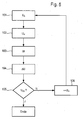
- Fig. 5 shows a flowchart of the method.
- the piezoelectric actuator 28 is energized when the output voltage U A is applied, so that the voltage U at the piezoelectric actuator 28 drops.
- the holding voltage U H the energization of the piezo-actuator 28 is interrupted in step 102.
- the interruption continues in step 103 for the period ⁇ t.
- the voltage U applied to the piezoelectric actuator 28 is measured.
- the voltage change .DELTA.U is measured over time.
- the voltage change ⁇ U is evaluated as described above.
- step 105 it is checked whether the voltage thus determined is the opening voltage of the injector.
- step 106 branches.
- the holding voltage U H is then increased, this is indicated here by a ++ U H , whereupon branches back to step 101.
Landscapes
- Engineering & Computer Science (AREA)
- Chemical & Material Sciences (AREA)
- Combustion & Propulsion (AREA)
- Mechanical Engineering (AREA)
- General Engineering & Computer Science (AREA)
- Fuel-Injection Apparatus (AREA)
- Electrical Control Of Air Or Fuel Supplied To Internal-Combustion Engine (AREA)
Abstract
Description
Die vorliegende Erfindung betrifft ein Verfahren zur Bestimmung einer Öffnungsspannung eines Injektors mit einem Piezo-Aktor, insbesondere eines Injektors einer Brennkraftmaschine, wobei im geschlossenen Zustand des Injektors eine Ausgangsspannung an den Piezo-Aktor angelegt wird und die Spannung zum Öffnen des Injektors durch Bestromung des Piezo-Aktors abgesenkt wird, sowie ein Steuergerät zur Durchführung des Verfahrens.The present invention relates to a method for determining an opening voltage of an injector with a piezoelectric actuator, in particular an injector of an internal combustion engine, wherein in the closed state of the injector, an output voltage is applied to the piezoelectric actuator and the voltage for opening the injector by energizing the piezoelectric Is lowered, and a control device for carrying out the method.
Düsennadeln von Kraftstoffinjektoren (Injektoren) für moderne Diesel- und Ottomotoren werden aufgrund der hohen dynamischen Anforderungen häufig direkt oder indirekt über piezoelektrische Elemente (piezoelektrische Aktoren oder Piezoaktoren) betätigt.Jet needles of fuel injectors (injectors) for modern diesel and gasoline engines are often actuated directly or indirectly via piezoelectric elements (piezoelectric actuators or piezoelectric actuators) due to the high dynamic requirements.
Die mechanischen und elektrischen Eigenschaften dieser piezoelektrischen Elemente bleiben über die Lebensdauer nicht konstant. Sowohl der Aktorhub als auch die Aktorkapazität und -steifigkeit ändern sich über die Lebensdauer. Diese Änderungen können im Betrieb ohne aufwendige Messtechnik nicht direkt erfasst und damit auch nicht kompensiert werden. Die Folge sind Fehler der eingespritzten Kraftstoffmenge.The mechanical and electrical properties of these piezoelectric elements do not remain constant over the lifetime. Both the actuator stroke and the actuator capacity and stiffness change over the lifetime. These changes can not be detected directly during operation without expensive measuring technology and thus can not be compensated. The result is errors in the injected fuel quantity.
Aus der
Eine Aufgabe der vorliegenden Erfindung ist es daher, ein Verfahren sowie ein Steuergerät zur Durchführung des Verfahrens anzugeben, mit denen die zuvor genannten Alterungserscheinungen erfasst und kompensiert werden können.An object of the present invention is therefore to provide a method and a control device for carrying out the method, with which the aforementioned aging phenomena can be detected and compensated.
Dieses Problem wird gelöst durch ein Verfahren zur Bestimmung einer Öffnungsspannung eines Injektors einer Brennkraftmaschine mit einem Piezo-Aktor, wobei im geschlossenen Zustand des Injektors eine Ausgangsspannung an den Piezo-Aktor angelegt wird und die Spannung zum Öffnen des Injektors durch Entladen des Piezo-Aktors abgesenkt wird, wobei die Entladung bei einer Haltespannung unterbrochen wird und danach die an dem Piezo-Aktor anliegende Spannungsänderung über der Zeit gemessen wird, wobei die Haltespannung von Einspritzung zu Einspritzung schrittweise erhöht wird bis der Spannungsanstieg nach Unterbrechung der Entladung einen Mindestwert unterschreitet, und wobei bei einem Spannungsanstieg um den Mindestwert darauf erkannt wird, dass die Haltespannung der Öffnungsspannung entspricht.This problem is solved by a method for determining an opening voltage of an injector of an internal combustion engine having a piezo actuator, wherein in the closed state of the injector, an output voltage is applied to the piezoelectric actuator and lowered the voltage for opening the injector by discharging the piezoelectric actuator is, wherein the discharge is interrupted at a holding voltage and then the voltage applied to the piezoelectric actuator voltage change over time is measured, wherein the holding voltage of injection to injection is gradually increased until the voltage increase after interruption of the discharge is below a minimum value, and wherein at a voltage increase around the minimum value is detected that the holding voltage corresponds to the opening voltage.
In einer Weiterbildung ist vorgesehen, dass die Haltespannung von Einspritzung zu Einspritzung schrittweise erhöht wird bis der Spannungsanstieg nach Unterbrechung der Bestromung einen Mindestgradienten unterschreitet.In a further development, it is provided that the holding voltage is increased step by step from injection to injection until the voltage increase falls below a minimum gradient after interruption of the current supply.
Das Verfahren wird vorzugsweise im regulären Betrieb der Brennkraftmaschine durchgeführt. Damit ist gemeint, dass das Verfahren keine zusätzlichen Steuergeräte oder Prüfgeräte beispielsweise in einer Werkstatt bedarf, sondern mit den in einem Fahrzeug vorhandenen Mitteln durchgeführt wird. Das Verfahren wird vorzugsweise nach Ablauf eines Intervalls einer Betriebszeit oder Ablauf einer Zeitspanne automatisch von einem Steuergerät programmgesteuert durchgeführt.The method is preferably carried out in regular operation of the internal combustion engine. This means that the method requires no additional control devices or test equipment, for example in a workshop, but is carried out with the resources available in a vehicle. The method is preferably carried out automatically after a lapse of an operating time interval or a lapse of a period of time by a control unit in a program-controlled manner.
In einer Weiterbildung ist vorgesehen, dass die Haltespannung eines Injektors variiert wird und ein Integrator einer Mengen-Ausgleichs-Regelung beobachtet wird. In einer Weiterbildung ist vorgesehen, dass auf das Erreichen der Öffnungsspannung erkannt wird, wenn die Ansteuerzeiten und/oder Ansteuerspannungen des Injektors durch die Mengen-Ausgleichs-Regelung so verändert werden, dass eine größere Einspritzmenge bewirkt wird.In a further development, it is provided that the holding voltage of an injector is varied and an integrator of a quantity compensation control is observed. In a further development, it is provided that it is detected that the opening voltage has been reached when the activation times and / or activation voltages of the injector are changed by the quantity compensation control in such a way that a larger injection quantity is effected.
Das eingangs genannte Problem wird auch gelöst durch ein Steuergerät mit Mitteln zur Bestimmung einer Öffnungsspannung eines Injektors einer Brennkraftmaschine mit einem Piezo-Aktor, wobei im geschlossenen Zustand des Injektors eine Ausgangsspannung an den Piezo-Aktor angelegt wird und die Spannung zum Öffnen des Injektors durch Entladen des Piezo-Aktors abgesenkt wird, wobei die Entladung bei einer Haltespannung unterbrochen wird und danach die an dem Piezo-Aktor anliegende Spannungsänderung über der Zeit gemessen wird, wobei die Haltespannung von Einspritzung zu Einspritzung schrittweise erhöht wird bis der Spannungsanstieg nach Unterbrechung der Entladung einen Mindestwert unterschreitet, und wobei bei einem Spannungsanstieg um den Mindestwert darauf erkannt wird, dass die Haltespannung der Öffnungsspannung entspricht..The above-mentioned problem is also solved by a control device having means for determining an opening voltage of an injector of an internal combustion engine with a piezo actuator, wherein in the closed state of the injector, an output voltage is applied to the piezoelectric actuator and the voltage for opening the injector is lowered by discharging the piezoelectric actuator, wherein the discharge is interrupted at a holding voltage and then the voltage applied to the piezoelectric actuator voltage change over time is measured, wherein the holding voltage of injection to injection is gradually increased until the voltage increase after interruption of the discharge falls below a minimum value, and it is detected in a voltage increase to the minimum value that the holding voltage corresponds to the opening voltage.
Nachfolgend wird ein Ausführungsbeispiel der vorliegenden Erfindung anhand der beiliegenden Zeichnung näher erläutert. Dabei zeigen:
-
Fig. 1 das technische Umfeld der Erfindung; -
Fig. 2 ein Beispiel der Einspritzmenge eines piezoelektrischen Injektors über die anliegende Maximalspannung; -
Fig. 3 ein Beispiel eines Spannungsverlaufs an einem Piezoelement eines piezoelektrischen Injektors bei Unterbrechung der Bestromung; -
Fig. 4 eine vergrößerte Darstellung des Bereiches X inFig. 3 ; -
Fig. 5 ein Ablaufdiagramm des Verfahrens.
-
Fig. 1 the technical environment of the invention; -
Fig. 2 an example of the injection quantity of a piezoelectric injector on the applied maximum voltage; -
Fig. 3 an example of a voltage waveform on a piezoelectric element of a piezoelectric injector when interrupting the energization; -
Fig. 4 an enlarged view of the area X inFig. 3 ; -
Fig. 5 a flowchart of the method.
Der Piezo-Aktor 28 ist über einen hydraulischen Koppler 34 mit einer Düsennadel 36 verbunden und wird von dem Steuergerät 14 gesteuert, das dazu eine Leistungs- und Messelektronik 38 und ein Steuerteil 4 0 aufweist. Der Koppler 34 weist eine Drossel 42 auf. Die Drossel 42 erlaubt einen langsam erfolgenden Ausgleich der Drücke innerhalb und außerhalb des Kopplers 34, so dass nur schnelle Längenänderungen des Piezo-Aktors 28 auf die Düsennadel 36 übertragen werden, langsame, thermisch induzierte Volumenänderungen aber ausgeglichen werden.The
Der Steuereingriff auf die Leistungs- und Messelektronik 38 wird in der
Wie in der
In
Wird die Entladung erst bei der Haltespannung UH3 von etwa 65 Volt unterbrochen, dies ist bei einer Zeit t31 der Fall, so sinkt zunächst die Spannung weiter ab, bis zu einem Zeitpunkt t33 und steigt danach wieder an. Der Anstieg erfolgt praktisch bis zum Wiedereinsetzen der Bestromung zum Zeitpunkt der Bestromung t23 und umfasst einen Spannungshub ΔU3 von etwa 5 V. Der Spannungshub ist hier also größer als bei der Haltespannung UH1 von etwa 85 Volt und weist kein ausgeprägtes lokales Maximum auf, wie dies zum Zeitpunkt t31 bei der Haltespannung UH1 von 85 Volt der Fall ist. Der deutliche Anstieg der Spannung U über dem Piezoelement in der Bestromungspause bei der Haltespannung UH1 von 65 V ist darauf zurückzuführen, dass der Injektor 12 öffnet.If the discharge is interrupted only at the holding voltage U H3 of about 65 volts, this is the case at a time t 31 , the voltage initially drops further, until a time t 33 and then rises again. The increase takes place virtually until the energization is restored to the time of the energization t 23 and comprises a voltage swing .DELTA.U 3 of about 5 V. The voltage swing is thus greater than at the holding voltage U H1 of about 85 volts and has no pronounced local maximum, as is the case at the time t 31 at the holding voltage U H1 of 85 volts. The significant increase in the voltage U across the piezoelectric element in the energization break at the holding voltage U H1 of 65 V is due to the fact that the
Je höher der Spannungshub des Piezo-Aktors 28, umso stärker wird die Nadel durch eine Druckabsenkung hydraulischen Koppler 34 entlastet. Ab einem gewissen Spannungshub wird die Nadel so weit aus dem Sitz gehoben, dass sie durch eine Druckunterwanderung schlagartig nach oben schnappt, bis ein Kräftegleichgewicht über den steigenden Druck im hydraulischen Koppler 34 zwischen Aktorkraft und Nadelkraft hergestellt ist. Der zuvor gedehnte Verbund bestehend aus Aktor, Nadel und der Kopplung von Koppler und Nadel wird dabei wieder gestaucht. Durch diese Stauchung wird über den piezoelektrischen Effekt in dem piezoelektrischen Aktor eine elektrische Spannung in dem Piezo-Aktor 28 induziert, die in der Entladepause Δt sichtbar wird.The higher the voltage stroke of the piezo-
Wird in der Entladepause Δt ein Spannungsanstieg mit stets positivem Gradienten ab Erreichen des Minimalwertes bei t3n beobachtet, so hat der Injektor 12 geöffnet. Wird eine Spannungsanhebung oberhalb eines Minimalwertes ΔUmin, im vorliegenden Beispiel der
Auf ein Öffnen des Injektors 12 kann ebenfalls geschlossen werden, wenn der Spannungsgradient ΔU/Δt einen Mindestwert erreicht. Hier kann beispielsweise der Gradient kurz vor Wiedereinsetzen der Bestromung im Zeitpunkt t2n betrachtet werden. Ist dieser deutlich positiv, so kann von einer erfolgten Einspritzung ausgegangen werden. Der Gradient im Bereich kurz nach Erreichen des lokalen Minimums bei der Zeit t3n ist stets positiv und eignet sich nicht für diese Betrachtung.Opening of the
Mit dem zuvor beschriebenen erfindungsgemäßen Verfahren ist es möglich, im Betrieb einer Brennkraftmaschine festzustellen, bei welchem Spannungshub oder ausgehend von einer konstanten Schließspannung bei welcher Öffnungsspannung ein Injektor 12 öffnet. Das Verfahren kann im regulären Betrieb der Brennkraftmaschine durchgeführt werden, indem der Spannungshub schrittweise bei aufeinander folgenden Einspritzungen verringert wird. Sobald in der Entladepause Δt (Bestromungspause) ein negativer Spannungsgradient, wie beispielsweise in Kurve 1 der
Zur Durchführung des Verfahrens können in einem Ausführungsbeispiel während des Fahrzeugbetriebes die Ansteuerspannungen einzelner Injektoren 12 wie zuvor beschrieben variiert werden und dabei die Integratoren der Mengen-Ausgleichs-Regelung (MAR) beobachtet werden. Die Mengen-Ausgleichs-Regelung sorgt für eine Gleichstellung der einzelnen Zylinder, dass also von den einzelnen Zylindern ein möglichst gleicher Anteil am Gesamtdrehmoment der Brennkraftmaschine beigesteuert wird, was in der Regel auf gleiche Einspritzmengen hinausläuft. Die Mengen-Ausgleichs-Regelung wird bei einer Veränderung des Spannungshubes eines Injektors 12 und damit einhergehender Verringerung der Einspritzmenge die Ansteuerzeiten bzw. Ansteuerspannungen so verändern, dass eine größere Einspritzmenge bewirkt wird. Sobald bei einer Veränderung des Spannungshubes wie zuvor beschrieben der Integrator des zu überprüfenden Injektors 12 steil nach oben verläuft, ist die kritische Ansteuerspannung bzw. der kritische Spannungshub erreicht, wobei die eingespritzte Kraftstoffmenge schlagartig abfällt.For carrying out the method, in one exemplary embodiment during vehicle operation, the drive voltages of
Claims (7)
- Method of determining an opening voltage of an injector (12) of an internal combustion engine having a piezo-actuator (28), wherein in the closed state of the injector (12) an output voltage (UA) is applied to the piezo-actuator (28) and the voltage (UA) is lowered in order to open the injector (12) while discharging the piezo-actuator (28), characterized in that the discharge is interrupted when there is holding voltage (UH1, UH2, UH3, ... UHn), and afterwards the voltage change (ΔU), and afterwards the voltage change (ΔU) which is applied to the piezo-actuator (28) is measured over time, wherein the holding voltage (UH1, UH2, UH3, ... UHn) is increased incrementally from injection to injection until the increase in voltage drops below a minimum value (ΔUmin) after an interruption of the discharge, and wherein, when there is an increase in voltage by the minimum value (ΔUmin), it is detected that the holding voltage (UH1, UH2, UH3, ... UHn) corresponds to the opening voltage (UOE).
- Method according to Claim 1, characterized in that the holding voltage (UH1, UH2, UH3, ... UHn) is increased incrementally from injection to injection until the voltage increase (ΔUmin) drops below a minimum gradient (Δmin/Δt) after interruption of the energization.
- Method according to one of the preceding claims, characterized in that this takes place during operation of the internal combustion engine.
- Method according to one of the preceding claims, characterized in that this takes place after expiry of an interval of an operating time or expiry of a time period.
- Method according to one of the preceding claims, characterized in that the holding voltage (UH1, UH2, UH3, ... UHn) of an injector (12) is varied, and an integrator of a quantity compensation control system is observed.
- Method according to Claim 5, characterized in that it is detected that the opening voltage (UOE) has been reached when the actuation times and/or actuation voltages of the injector (12) are changed by the quantity compensation control system in such a way that a relatively large injection quantity is brought about.
- Control device having means for determining an opening voltage of an injector (12) of an internal combustion engine having a piezo-actuator (28), wherein in the closed state of the injector (12) an output voltage (UA) is applied to the piezo-actuator (28) and the voltage (U) is lowered in order to open the injector (12) by discharging the piezo-actuator (28), characterized in that the discharge is interrupted when there is holding voltage (UH1, UH2, UH3, ... UHn), and afterwards the voltage change (ΔU) which is applied to the piezo-actuator (28) is measured over time, wherein the holding voltage (UH1, UH2, UH3, ... UHn) is increased incrementally from injection to injection until the increase in voltage drops below a minimum value (ΔUmin) after an interruption of the discharge, and wherein, when there is an increase in voltage by the minimum value (ΔUmin) , it is detected that the holding voltage (UH1, UH2, UH3, ... UHn), corresponds to the opening voltage (UOE).
Applications Claiming Priority (2)
| Application Number | Priority Date | Filing Date | Title |
|---|---|---|---|
| DE102006013166A DE102006013166A1 (en) | 2006-03-22 | 2006-03-22 | Method for determining an opening voltage of a piezoelectric injector |
| PCT/EP2007/052378 WO2007107484A1 (en) | 2006-03-22 | 2007-03-14 | Method of determining an opening voltage of a piezoelectric injector |
Publications (2)
| Publication Number | Publication Date |
|---|---|
| EP1999359A1 EP1999359A1 (en) | 2008-12-10 |
| EP1999359B1 true EP1999359B1 (en) | 2012-02-29 |
Family
ID=38162210
Family Applications (1)
| Application Number | Title | Priority Date | Filing Date |
|---|---|---|---|
| EP07712521A Not-in-force EP1999359B1 (en) | 2006-03-22 | 2007-03-14 | Method of determining an opening voltage of a piezoelectric injector |
Country Status (5)
| Country | Link |
|---|---|
| US (1) | US20100275885A1 (en) |
| EP (1) | EP1999359B1 (en) |
| JP (1) | JP4705689B2 (en) |
| DE (1) | DE102006013166A1 (en) |
| WO (1) | WO2007107484A1 (en) |
Families Citing this family (11)
| Publication number | Priority date | Publication date | Assignee | Title |
|---|---|---|---|---|
| DE102007020061B3 (en) * | 2007-04-27 | 2008-10-16 | Siemens Ag | Method and data carrier for reading out and / or storing injector-specific data for controlling an injection system of an internal combustion engine |
| DE102007042994A1 (en) | 2007-09-10 | 2009-03-12 | Robert Bosch Gmbh | Method for assessing an operation of an injection valve when applying a drive voltage and corresponding evaluation device |
| DE102009027311A1 (en) * | 2009-06-30 | 2011-01-05 | Robert Bosch Gmbh | Method for operating an internal combustion engine |
| DE102010021169B4 (en) * | 2010-05-21 | 2012-03-08 | Continental Automotive Gmbh | Method and device for determining the actual start of injection of a piezo fuel injector |
| DE102012209965A1 (en) * | 2012-06-14 | 2013-12-19 | Robert Bosch Gmbh | Method for operating a valve |
| DE102013223750B3 (en) * | 2013-11-21 | 2015-02-19 | Continental Automotive Gmbh | Method for determining the valve opening time for piezoservo driven injectors |
| DE102013223756B4 (en) * | 2013-11-21 | 2015-08-27 | Continental Automotive Gmbh | Method for operating injectors of an injection system |
| DE102014209326A1 (en) * | 2014-05-16 | 2015-11-19 | Robert Bosch Gmbh | Method for determining a closing time of a fuel injector |
| DE102014209823B4 (en) | 2014-05-23 | 2016-03-31 | Continental Automotive Gmbh | Method for determining the closing characteristic of the control valve of a piezo servo injector |
| US10401398B2 (en) | 2017-03-03 | 2019-09-03 | Woodward, Inc. | Fingerprinting of fluid injection devices |
| US10393056B2 (en) * | 2017-05-10 | 2019-08-27 | Ford Global Technologies, Llc | Method and system for characterizing a port fuel injector |
Family Cites Families (12)
| Publication number | Priority date | Publication date | Assignee | Title |
|---|---|---|---|---|
| JP2548563B2 (en) * | 1987-04-25 | 1996-10-30 | 株式会社ゼクセル | Needle lift detection signal discrimination circuit |
| JPH10288119A (en) * | 1997-04-18 | 1998-10-27 | Nissan Motor Co Ltd | Driving device of fuel injection valve |
| DE19930309C2 (en) * | 1999-07-01 | 2001-12-06 | Siemens Ag | Method and device for regulating the injection quantity in a fuel injection valve with a piezo element actuator |
| JP4168564B2 (en) * | 2000-02-01 | 2008-10-22 | 株式会社デンソー | Fuel injection device |
| US6420817B1 (en) * | 2000-02-11 | 2002-07-16 | Delphi Technologies, Inc. | Method for detecting injection events in a piezoelectric actuated fuel injector |
| DE10024662B4 (en) * | 2000-05-18 | 2005-12-15 | Siemens Ag | Method for operating an injection valve |
| DE10357481A1 (en) * | 2003-12-09 | 2005-07-14 | Siemens Ag | Operating method for an actuator of an injection valve |
| DE10357872A1 (en) * | 2003-12-11 | 2005-07-07 | Robert Bosch Gmbh | Method and device for determining the drive voltage for a piezoelectric actuator of an injection valve |
| WO2005119038A1 (en) * | 2004-06-03 | 2005-12-15 | Siemens Aktiengesellschaft | Method and device for controlling an injection valve |
| DE102004037255B4 (en) * | 2004-07-31 | 2016-06-09 | Robert Bosch Gmbh | Method for operating a fuel injection device, in particular for a motor vehicle |
| DE102006058744A1 (en) * | 2006-12-12 | 2008-06-19 | Robert Bosch Gmbh | Method for operating an injection valve |
| AU2009201607B2 (en) * | 2008-04-23 | 2011-10-06 | Woongjin Coway Co., Ltd. | Device and method for detecting zero crossing and voltage amplitude from single pulse signal |
-
2006
- 2006-03-22 DE DE102006013166A patent/DE102006013166A1/en not_active Withdrawn
-
2007
- 2007-03-14 US US12/225,354 patent/US20100275885A1/en not_active Abandoned
- 2007-03-14 EP EP07712521A patent/EP1999359B1/en not_active Not-in-force
- 2007-03-14 JP JP2009500823A patent/JP4705689B2/en not_active Expired - Fee Related
- 2007-03-14 WO PCT/EP2007/052378 patent/WO2007107484A1/en active Application Filing
Also Published As
| Publication number | Publication date |
|---|---|
| JP2009530538A (en) | 2009-08-27 |
| EP1999359A1 (en) | 2008-12-10 |
| US20100275885A1 (en) | 2010-11-04 |
| WO2007107484A1 (en) | 2007-09-27 |
| DE102006013166A1 (en) | 2007-09-27 |
| JP4705689B2 (en) | 2011-06-22 |
Similar Documents
| Publication | Publication Date | Title |
|---|---|---|
| EP1999359B1 (en) | Method of determining an opening voltage of a piezoelectric injector | |
| EP0929911B1 (en) | Method and device for charging and discharging a piezoelectric element | |
| DE102004009373B4 (en) | Piezo actuator drive circuit | |
| EP0986702B1 (en) | Method for controlling at least one capacitive actuating element | |
| DE60011038T2 (en) | Time and case-controlled activation system for charging and discharging piezoelectric elements | |
| DE102009018289B3 (en) | Method and device for operating an injection valve | |
| DE60018549T2 (en) | fuel injection system | |
| DE102011075732A1 (en) | Control method for an injection valve and injection system | |
| EP0983614A1 (en) | Method and device for determining the temperature of a piezo-electric element | |
| DE10033343A1 (en) | Fuel injection system for an internal combustion engine | |
| DE60011993T2 (en) | Apparatus and method for determining a reduction in capacitance while driving piezoelectric elements | |
| DE19652809C1 (en) | Method and device for controlling at least one capacitive actuator | |
| DE10336639A1 (en) | Method and device for functional diagnosis of a piezoelectric actuator of a fuel metering system of an internal combustion engine | |
| EP1613851B1 (en) | Method for determining the individual control voltage of a piezoelectric element | |
| DE10357872A1 (en) | Method and device for determining the drive voltage for a piezoelectric actuator of an injection valve | |
| EP1917568B1 (en) | Current source and control device | |
| DE19952774B4 (en) | Device for draining fluid from a system | |
| WO2007028737A1 (en) | Method and apparatus for operation of a piezo-actuator | |
| DE102005057572A1 (en) | Method for operating piezo actuator of fuel injector in accumulator type injection system for IC engine, involves evaluating piezo voltage of piezo actuator by acquiring two values of piezo voltage in response to change in fuel pressure | |
| DE102006021299A1 (en) | Internal-combustion engine`s e.g. diesel engine, injector controlling method, involves applying output voltage to piezo-actuator, and changing opening voltage to offset voltage and applying for distributing injection of injecting voltage | |
| DE60018897T2 (en) | Controlling the polarization of the piezoelectric elements before each first injection to achieve optimal starting conditions | |
| DE10303975B4 (en) | Piezo actuator control unit, piezo actuator control method and fuel injection system | |
| DE102007058540B4 (en) | Method and apparatus for charging and discharging a piezoelectric element | |
| DE10323488B4 (en) | Method and device for operating point-dependent control of injectors of a fuel metering system of an internal combustion engine | |
| DE102006055259A1 (en) | Injected fuel e.g. diesel, amount determining method, involves evaluating rise of voltage signal, and determining measure for movement of nozzle needle and measure for injected amount of fuel based on increase in voltage signal |
Legal Events
| Date | Code | Title | Description |
|---|---|---|---|
| PUAI | Public reference made under article 153(3) epc to a published international application that has entered the european phase |
Free format text: ORIGINAL CODE: 0009012 |
|
| 17P | Request for examination filed |
Effective date: 20081022 |
|
| AK | Designated contracting states |
Kind code of ref document: A1 Designated state(s): DE FR GB |
|
| DAX | Request for extension of the european patent (deleted) | ||
| RBV | Designated contracting states (corrected) |
Designated state(s): DE FR GB |
|
| 17Q | First examination report despatched |
Effective date: 20090925 |
|
| GRAP | Despatch of communication of intention to grant a patent |
Free format text: ORIGINAL CODE: EPIDOSNIGR1 |
|
| GRAS | Grant fee paid |
Free format text: ORIGINAL CODE: EPIDOSNIGR3 |
|
| GRAA | (expected) grant |
Free format text: ORIGINAL CODE: 0009210 |
|
| AK | Designated contracting states |
Kind code of ref document: B1 Designated state(s): DE FR GB |
|
| REG | Reference to a national code |
Ref country code: GB Ref legal event code: FG4D Free format text: NOT ENGLISH |
|
| RIN1 | Information on inventor provided before grant (corrected) |
Inventor name: BREITBACH, THOMAS Inventor name: BECKER, OLIVER |
|
| REG | Reference to a national code |
Ref country code: DE Ref legal event code: R096 Ref document number: 502007009371 Country of ref document: DE Effective date: 20120426 |
|
| PLBE | No opposition filed within time limit |
Free format text: ORIGINAL CODE: 0009261 |
|
| STAA | Information on the status of an ep patent application or granted ep patent |
Free format text: STATUS: NO OPPOSITION FILED WITHIN TIME LIMIT |
|
| GBPC | Gb: european patent ceased through non-payment of renewal fee |
Effective date: 20120529 |
|
| REG | Reference to a national code |
Ref country code: DE Ref legal event code: R119 Ref document number: 502007009371 Country of ref document: DE Effective date: 20121002 |
|
| 26N | No opposition filed |
Effective date: 20121130 |
|
| REG | Reference to a national code |
Ref country code: FR Ref legal event code: ST Effective date: 20130104 |
|
| PG25 | Lapsed in a contracting state [announced via postgrant information from national office to epo] |
Ref country code: FR Free format text: LAPSE BECAUSE OF NON-PAYMENT OF DUE FEES Effective date: 20120430 |
|
| PG25 | Lapsed in a contracting state [announced via postgrant information from national office to epo] |
Ref country code: GB Free format text: LAPSE BECAUSE OF NON-PAYMENT OF DUE FEES Effective date: 20120529 |
|
| PG25 | Lapsed in a contracting state [announced via postgrant information from national office to epo] |
Ref country code: DE Free format text: LAPSE BECAUSE OF FAILURE TO SUBMIT A TRANSLATION OF THE DESCRIPTION OR TO PAY THE FEE WITHIN THE PRESCRIBED TIME-LIMIT Effective date: 20121002 |