EP1999022B1 - Air inlet shroud structure - Google Patents
Air inlet shroud structure Download PDFInfo
- Publication number
- EP1999022B1 EP1999022B1 EP07731048A EP07731048A EP1999022B1 EP 1999022 B1 EP1999022 B1 EP 1999022B1 EP 07731048 A EP07731048 A EP 07731048A EP 07731048 A EP07731048 A EP 07731048A EP 1999022 B1 EP1999022 B1 EP 1999022B1
- Authority
- EP
- European Patent Office
- Prior art keywords
- nacelle
- casing
- attenuation structure
- sound attenuation
- acoustic attenuation
- Prior art date
- Legal status (The legal status is an assumption and is not a legal conclusion. Google has not performed a legal analysis and makes no representation as to the accuracy of the status listed.)
- Not-in-force
Links
Images

Classifications
-
- B—PERFORMING OPERATIONS; TRANSPORTING
- B64—AIRCRAFT; AVIATION; COSMONAUTICS
- B64D—EQUIPMENT FOR FITTING IN OR TO AIRCRAFT; FLIGHT SUITS; PARACHUTES; ARRANGEMENTS OR MOUNTING OF POWER PLANTS OR PROPULSION TRANSMISSIONS IN AIRCRAFT
- B64D33/00—Arrangements in aircraft of power plant parts or auxiliaries not otherwise provided for
- B64D33/02—Arrangements in aircraft of power plant parts or auxiliaries not otherwise provided for of combustion air intakes
-
- F—MECHANICAL ENGINEERING; LIGHTING; HEATING; WEAPONS; BLASTING
- F02—COMBUSTION ENGINES; HOT-GAS OR COMBUSTION-PRODUCT ENGINE PLANTS
- F02C—GAS-TURBINE PLANTS; AIR INTAKES FOR JET-PROPULSION PLANTS; CONTROLLING FUEL SUPPLY IN AIR-BREATHING JET-PROPULSION PLANTS
- F02C7/00—Features, components parts, details or accessories, not provided for in, or of interest apart form groups F02C1/00 - F02C6/00; Air intakes for jet-propulsion plants
- F02C7/04—Air intakes for gas-turbine plants or jet-propulsion plants
- F02C7/045—Air intakes for gas-turbine plants or jet-propulsion plants having provisions for noise suppression
-
- F—MECHANICAL ENGINEERING; LIGHTING; HEATING; WEAPONS; BLASTING
- F04—POSITIVE - DISPLACEMENT MACHINES FOR LIQUIDS; PUMPS FOR LIQUIDS OR ELASTIC FLUIDS
- F04D—NON-POSITIVE-DISPLACEMENT PUMPS
- F04D29/00—Details, component parts, or accessories
- F04D29/66—Combating cavitation, whirls, noise, vibration or the like; Balancing
- F04D29/661—Combating cavitation, whirls, noise, vibration or the like; Balancing especially adapted for elastic fluid pumps
- F04D29/663—Sound attenuation
- F04D29/664—Sound attenuation by means of sound absorbing material
-
- B—PERFORMING OPERATIONS; TRANSPORTING
- B64—AIRCRAFT; AVIATION; COSMONAUTICS
- B64D—EQUIPMENT FOR FITTING IN OR TO AIRCRAFT; FLIGHT SUITS; PARACHUTES; ARRANGEMENTS OR MOUNTING OF POWER PLANTS OR PROPULSION TRANSMISSIONS IN AIRCRAFT
- B64D33/00—Arrangements in aircraft of power plant parts or auxiliaries not otherwise provided for
- B64D33/02—Arrangements in aircraft of power plant parts or auxiliaries not otherwise provided for of combustion air intakes
- B64D2033/0206—Arrangements in aircraft of power plant parts or auxiliaries not otherwise provided for of combustion air intakes comprising noise reduction means, e.g. acoustic liners
-
- B—PERFORMING OPERATIONS; TRANSPORTING
- B64—AIRCRAFT; AVIATION; COSMONAUTICS
- B64D—EQUIPMENT FOR FITTING IN OR TO AIRCRAFT; FLIGHT SUITS; PARACHUTES; ARRANGEMENTS OR MOUNTING OF POWER PLANTS OR PROPULSION TRANSMISSIONS IN AIRCRAFT
- B64D33/00—Arrangements in aircraft of power plant parts or auxiliaries not otherwise provided for
- B64D33/02—Arrangements in aircraft of power plant parts or auxiliaries not otherwise provided for of combustion air intakes
- B64D2033/0266—Arrangements in aircraft of power plant parts or auxiliaries not otherwise provided for of combustion air intakes specially adapted for particular type of power plants
- B64D2033/0286—Arrangements in aircraft of power plant parts or auxiliaries not otherwise provided for of combustion air intakes specially adapted for particular type of power plants for turbofan engines
Definitions
- the present invention relates to a turbojet engine nacelle comprising an air intake structure capable of channeling a flow of air towards a fan of the turbojet engine and a median structure comprising a casing intended to surround said fan and to which the structure is attached.
- air inlet the latter having a peripheral inner surface at least partially equipped with an acoustic attenuation structure extending without geometrical rupture on at least a portion of the housing.
- An aircraft is propelled by one or more propulsion units comprising a turbojet engine housed in a tubular nacelle.
- Each propulsion unit is attached to the aircraft by a mast located generally under a wing or at the fuselage.
- a nacelle generally has a structure comprising an air inlet upstream of the engine, a median section intended to surround a fan of the turbojet, a downstream section housing thrust reverser means and intended to surround the combustion chamber of the turbojet engine, and is generally terminated by an ejection nozzle whose outlet is located downstream of the turbojet engine.
- the air intake comprises, on the one hand, an inlet lip adapted to allow optimal capture to the turbojet of the air necessary to supply the blower and the internal compressors of the turbojet engine, and other on the other hand, a downstream structure to which the lip is attached and intended to properly channel the air towards the blades of the fan.
- the assembly is attached upstream of a blower housing belonging to the upstream section of the nacelle.
- the document US 3,890,060 describes a nacelle having an acoustic attenuation structure extending from the downstream structure of the air inlet to the downstream end of the nacelle without geometrical rupture.
- the document GB 2,065,766 describes a space between an acoustic attenuation structure and the housing of a turbojet engine.
- the object of the present invention is to overcome the drawbacks previously mentioned and consists of a turbojet engine nacelle comprising an air intake structure capable of channeling an air flow towards a fan of the turbojet engine and a central structure comprising a crankcase. intended to surround said fan and to which is attached the air intake structure, the latter having a peripheral inner surface at least partially equipped with an acoustic attenuation structure extending without geometrical rupture on at least a portion of the housing , characterized in that a space is provided between the acoustic attenuation structure and the housing.
- the portion of the acoustic attenuation structure extending at the crankcase can be subjected in flight to greater or lesser vibrations depending on the length of the acoustic attenuation structure protruding at the crankcase, these vibrations being transmitted to the whole of the nacelle and in particular to the rest of the acoustic attenuation structure, thereby creating more or less significant deformations which in turn cause aerodynamic and acoustic disturbances due to the break in continuity of the aerodynamic lines of the sound attenuation structure.
- the following improvements make it possible to overcome these additional disadvantages.
- the acoustic attenuation structure comprises at least one structural reinforcement means.
- the structural reinforcement means comprise a sheath, reported or integrated in the acoustic attenuation structure.
- the sleeve has, at the housing, a decreasing thickness in the direction of the fan.
- This inclined shape of the sleeve makes it possible to provide a conical structure at the level of the casing, this shape being reflected by complementarity on the casing itself, which then ensures a direction of transit of the forces close to an alignment with the rest of the casing.
- the acoustic attenuation structure is associated, at the housing, with at least one vibration damping means.
- the damping means comprise an abutment system mounted on the housing and adapted to prevent a closer approximation of the acoustic attenuation structure.
- the damping means comprise at least one resilient member mounted against the acoustic attenuation structure. It may, for example, be an elastic blade bearing on the one hand, on the acoustic attenuation structure, and on the other hand, on the housing, or a spring.
- the damping means are able to come into contact with the acoustic attenuation structure via at least one flexible abutment means.
- the acoustic attenuation structure has a downstream end adapted to cooperate with at least one complementary holding means integral with the housing.
- the complementary holding means comprises at least one pin capable of cooperating with a corresponding housing fitted or formed in the downstream end of the acoustic attenuation structure.
- the housing has at least one heel piece adapted to support the acoustic attenuation structure at its downstream end.
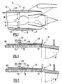
- a nacelle 1 according to the invention as represented on the figure 1 is a tubular housing for a turbojet engine 2 which it serves to channel the air flows it generates by defining internal and external aerodynamic lines necessary for obtaining optimal performance. She It also houses various components necessary for the operation of the turbojet engine 2 and related systems such as a thrust reverser.
- the nacelle 1 has a structure comprising a front section forming an air inlet 4, a median section 5 surrounding a fan 6 of the turbojet engine 2, and a rear section 7 surrounding the turbojet engine 2 and housing a reversing system. thrust (not visible).
- the air intake 4 is divided into two parts, namely on the one hand, an inlet lip 4a adapted to allow optimum capture to the turbojet 2 of the air necessary to supply the fan 6 and internal compressors of the turbojet engine 2, and secondly, a downstream structure 4b on which is reported the lip 4a and for properly channeling the air to the vanes 8 of the blower 6.
- the assembly is attached upstream of a casing 9 of the blower 6 belonging to the median section 5 of the nacelle 1 via fastening flanges 10, 11 integral respectively with the downstream structure 4b and the casing 9 and forming a junction 12.
- the downstream structure 4b is equipped, on the inside, with an acoustic attenuation structure 13 extending beyond the junction 12 at least partially inside the housing 9.
- the casing 9 is designed so as to provide a space 14 between said casing 9 and the acoustic attenuation structure 13, the continuity of the aerodynamic line of the interior of the nacelle 1 being effected at one end 15. the acoustic attenuation structure which is in contact with the housing 9 just before dawn 8.
- the Figures 2 and 3 show an improvement of this arrangement according to which the acoustic attenuation structure comprises structural reinforcement means. Indeed, in flight, the part of the acoustic attenuation structure 13 extending at the housing 9 is subjected to more or less significant vibrations which in turn create aerodynamic and acoustic disturbances.
- the acoustic attenuation structure 13 comprises a sleeve 16, attached or integrated to the acoustic attenuation structure 13.
- this sleeve 16 has, for the portion of the acoustic attenuation structure 13 extending inside the housing 9, a decreasing thickness in the direction of the fan 6 thus conferring a conical shape.
- the housing 9 is adapted accordingly to reflect this shape, then conferring on the upstream part of the casing a direction of transit of effort close to alignment with the rest of the casing 9.
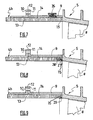
- the casing 9 is equipped with at least one means for attenuating the vibrations of the acoustic attenuation structure 13.
- Various embodiments are represented on the Figures 4 to 7 .
- the housing 9 is equipped with an abutment means 18 secured to the casing 9 by fastening means 19.
- the stop means 18 has a head 20 passing through the casing 9 and terminated by a flexible abutment 21 in contact with the structure of the housing. acoustic attenuation 13.
- the housing 9 is equipped with a vibration absorption system 22 in rigid contact with the acoustic attenuation structure 13 via a point stop 23.
- the vibration absorption system 22 can be set to the desired pressure.
- the abutment 23 may optionally be flexible.
- the housing 9 is equipped with an elastic blade 24 located in the space 14 and is supported on the one hand on the housing 9, and on the other hand, on the acoustic attenuation structure 13 which it absorbs the vibrations.
- the spring 26 and the elastic blade 24 have a stiffness adapted to the vibrations to be absorbed.
- the casing 9 is equipped with at least one holding means of which two examples are shown on the figure 8 and 9 .
- the housing 9 is equipped with a pin 27 adapted to cooperate in complementary form with a housing 28 formed in the acoustic attenuation structure 13.
- This housing 28 can be attached to the acoustic attenuation structure 13 or integrated with that -this.
- the housing 9 is equipped with a full or partial heel 29, advantageously positioned on the inner periphery of the casing 9 at the junction with the acoustic attenuation structure 13 near the blower 6 and able to come into operation. support of the acoustic attenuation structure 13.
- a shape, for example in chamfer, centering aid may possibly be practiced in the acoustic attenuation structure 13.
Abstract
Description
La présente invention se rapporte à une nacelle pour turboréacteur comprenant une structure d'entrée d'air apte à canaliser un flux d'air vers une soufflante du turboréacteur et une structure médiane comportant un carter destiné à entourer ladite soufflante et auquel est rattaché la structure d'entrée d'air, cette dernière présentant une surface intérieure périphérique au moins partiellement équipée d'une structure d'atténuation acoustique s'étendant sans rupture géométrique sur au moins une partie du carter.The present invention relates to a turbojet engine nacelle comprising an air intake structure capable of channeling a flow of air towards a fan of the turbojet engine and a median structure comprising a casing intended to surround said fan and to which the structure is attached. air inlet, the latter having a peripheral inner surface at least partially equipped with an acoustic attenuation structure extending without geometrical rupture on at least a portion of the housing.
Un avion est propulsé par un ou plusieurs ensembles propulsifs comprenant un turboréacteur logeant dans une nacelle tubulaire. Chaque ensemble propulsif est rattaché à l'avion par un mât situé généralement sous une aile ou au niveau du fuselage.An aircraft is propelled by one or more propulsion units comprising a turbojet engine housed in a tubular nacelle. Each propulsion unit is attached to the aircraft by a mast located generally under a wing or at the fuselage.
Une nacelle présente généralement une structure comprenant une entrée d'air en amont du moteur, une section médiane destinée à entourer une soufflante du turboréacteur, une section aval abritant des moyens d'inversion de poussée et destinée à entourer la chambre de combustion du turboréacteur, et est généralement terminée par une tuyère d'éjection dont la sortie est située en aval du turboréacteur.A nacelle generally has a structure comprising an air inlet upstream of the engine, a median section intended to surround a fan of the turbojet, a downstream section housing thrust reverser means and intended to surround the combustion chamber of the turbojet engine, and is generally terminated by an ejection nozzle whose outlet is located downstream of the turbojet engine.
L'entrée d'air comprend, d'une part, une lèvre d'entrée adaptée pour permettre la captation optimale vers le turboréacteur de l'air nécessaire à l'alimentation de la soufflante et des compresseurs internes du turboréacteur, et d'autre part, une structure aval sur laquelle est rapportée la lèvre et destinée à canaliser convenablement l'air vers les aubes de la soufflante. L'ensemble est rattaché en amont d'un carter de la soufflante appartenant à la section amont de la nacelle.The air intake comprises, on the one hand, an inlet lip adapted to allow optimal capture to the turbojet of the air necessary to supply the blower and the internal compressors of the turbojet engine, and other on the other hand, a downstream structure to which the lip is attached and intended to properly channel the air towards the blades of the fan. The assembly is attached upstream of a blower housing belonging to the upstream section of the nacelle.
Le document
Le document
Le document
Toutefois, il a été constaté que lorsque l'on souhaite installer une structure d'atténuation acoustique s'étendant depuis la structure aval de la structure d'entrée d'air jusqu'au carter, l'ensemble ainsi fixé devient hyperstatique entre la bride d'attache de la structure d'atténuation acoustique de la structure d'entrée d'air aval et la bride d'attache du carter.However, it has been found that when it is desired to install an acoustic attenuation structure extending from the downstream structure of the air intake structure to the casing, the assembly thus fixed becomes hyperstatic between the fastening flange of the acoustic attenuation structure of the downstream air inlet structure and the housing fastening flange.
La présente invention a pour but de pallier les inconvénients précédemment évoqués et consiste pour cela en une nacelle pour turboréacteur comprenant une structure d'entrée d'air apte à canaliser un flux d'air vers une soufflante du turboréacteur et une structure médiane comportant un carter destiné à entourer ladite soufflante et auquel est rattaché la structure d'entrée d'air, cette dernière présentant une surface intérieure périphérique au moins partiellement équipée d'une structure d'atténuation acoustique s'étendant sans rupture géométrique sur au moins une partie du carter, caractérisée en ce qu'un espace est ménagé entre la structure d'atténuation acoustique et le carter.The object of the present invention is to overcome the drawbacks previously mentioned and consists of a turbojet engine nacelle comprising an air intake structure capable of channeling an air flow towards a fan of the turbojet engine and a central structure comprising a crankcase. intended to surround said fan and to which is attached the air intake structure, the latter having a peripheral inner surface at least partially equipped with an acoustic attenuation structure extending without geometrical rupture on at least a portion of the housing , characterized in that a space is provided between the acoustic attenuation structure and the housing.
Ainsi, en prévoyant un espace entre le carter et la structure d'atténuation acoustique, cette dernière n'est plus directement liée au carter, réduisant de ce fait le degré d'hyperstaticité.Thus, by providing a space between the housing and the acoustic attenuation structure, the latter is no longer directly related to the housing, thereby reducing the degree of hyperstaticity.
Toutefois, la partie de la structure d'atténuation acoustique s'étendant au niveau du carter peut être soumise en vol à des vibrations plus ou moins importantes selon la longueur de la structure d'atténuation acoustique dépassant au niveau du carter, ces vibrations se transmettant à l'ensemble de la nacelle et notamment au reste de la structure d'atténuation acoustique, créant de ce fait des déformations plus ou moins importantes qui entraînent à leur tour des perturbations aérodynamiques et acoustiques dues à la rupture de continuité des lignes aérodynamiques de la structure d'atténuation acoustique. Les améliorations suivantes permettent de pallier ces inconvénients additionnels.However, the portion of the acoustic attenuation structure extending at the crankcase can be subjected in flight to greater or lesser vibrations depending on the length of the acoustic attenuation structure protruding at the crankcase, these vibrations being transmitted to the whole of the nacelle and in particular to the rest of the acoustic attenuation structure, thereby creating more or less significant deformations which in turn cause aerodynamic and acoustic disturbances due to the break in continuity of the aerodynamic lines of the sound attenuation structure. The following improvements make it possible to overcome these additional disadvantages.
Avantageusement, la structure d'atténuation acoustique comprend au moins un moyen de renforcement structurel.Advantageously, the acoustic attenuation structure comprises at least one structural reinforcement means.
Préférentiellement, les moyens de renforcement structurel comprennent un fourreau, rapporté ou intégré à la structure d'atténuation acoustique.Preferably, the structural reinforcement means comprise a sheath, reported or integrated in the acoustic attenuation structure.
Préférentiellement encore, le fourreau possède, au niveau du carter, une épaisseur décroissante en direction de la soufflante. Cette forme inclinée du fourreau permet de fournir une structure conique au niveau du carter, cette forme se reflétant par complémentarité sur le carter lui-même, qui assure alors une direction de transit des efforts proche d'un alignement avec le reste du carter.Preferably, the sleeve has, at the housing, a decreasing thickness in the direction of the fan. This inclined shape of the sleeve makes it possible to provide a conical structure at the level of the casing, this shape being reflected by complementarity on the casing itself, which then ensures a direction of transit of the forces close to an alignment with the rest of the casing.
De manière avantageuse, la structure d'atténuation acoustique est associée, au niveau du carter, avec au moins un moyen d'amortissement des vibrations.Advantageously, the acoustic attenuation structure is associated, at the housing, with at least one vibration damping means.
Préférentiellement, les moyens d'amortissement comprennent un système de butée monté sur le carter et apte à empêcheur un rapprochement de la structure d'atténuation acoustique.Preferably, the damping means comprise an abutment system mounted on the housing and adapted to prevent a closer approximation of the acoustic attenuation structure.
Avantageusement, les moyens d'amortissement comprennent au moins un organe élastique monté à l'encontre de la structure d'atténuation acoustique. Il pourra, par exemple, s'agir d'une lame élastique prenant appui, d'une part, sur la structure d'atténuation acoustique, et d'autre part, sur le carter, ou encore d'un ressort.Advantageously, the damping means comprise at least one resilient member mounted against the acoustic attenuation structure. It may, for example, be an elastic blade bearing on the one hand, on the acoustic attenuation structure, and on the other hand, on the housing, or a spring.
Préférentiellement, les moyens d'amortissement sont aptes à venir au contact de la structure d'atténuation acoustique par l'intermédiaire d'au moins un moyen de butée souple.Preferably, the damping means are able to come into contact with the acoustic attenuation structure via at least one flexible abutment means.
De manière additionnelle, la structure d'atténuation acoustique présente une extrémité aval apte à coopérer avec au moins un moyen de maintien complémentaire solidaire du carter.Additionally, the acoustic attenuation structure has a downstream end adapted to cooperate with at least one complementary holding means integral with the housing.
Avantageusement, le moyen de maintien complémentaire comprend au moins un pion apte à coopérer avec un logement correspondant rapporté ou ménagé dans l'extrémité aval de la structure d'atténuation acoustique.Advantageously, the complementary holding means comprises at least one pin capable of cooperating with a corresponding housing fitted or formed in the downstream end of the acoustic attenuation structure.
Avantageusement encore, le carter présente au moins une talonnette apte à venir supporter la structure d'atténuation acoustique au niveau de son extrémité aval.Advantageously, the housing has at least one heel piece adapted to support the acoustic attenuation structure at its downstream end.
La mise en oeuvre de l'invention sera mieux comprise à l'aide de la description détaillée qui est exposée ci-dessous en regard du dessin annexé dans lequel :
- La
figure 1 est une représentation schématique de la structure générale d'une nacelle de turboréacteur selon l'invention. - Les
figures 2 à 9 sont des représentations schématiques partielles de la jonction entre une structure d'entrée d'air et un carter de la nacelle de lafigure 1 .
- The
figure 1 is a schematic representation of the general structure of a turbojet engine nacelle according to the invention. - The
Figures 2 to 9 are partial schematic representations of the junction between an air intake structure and a crankcase of the nacelle of thefigure 1 .
Une nacelle 1 selon l'invention telle que représentée sur la
Plus précisément, la nacelle 1 possède une structure comprenant une section avant formant une entrée d'air 4, une section médiane 5 entourant une soufflante 6 du turboréacteur 2, et une section arrières 7 entourant le turboréacteur 2 et abritant un système d'inversion de poussée (non visible).More specifically, the nacelle 1 has a structure comprising a front section forming an air inlet 4, a
L'entrée d'air 4 se divise en deux parties, à savoir d'une part, une lèvre 4a d'entrée adaptée pour permettre la captation optimale vers le turboréacteur 2 de l'air nécessaire à l'alimentation de la soufflante 6 et des compresseurs internes du turboréacteur 2, et d'autre part, une structure aval 4b sur laquelle est rapportée la lèvre 4a et destinée à canaliser convenablement l'air vers les aubes 8 de la soufflante 6. L'ensemble est rattaché en amont d'un carter 9 de la soufflante 6 appartenant à la section médiane 5 de la nacelle 1 par l'intermédiaire de brides de fixation 10, 11 solidaires respectivement de la structure aval 4b et du carter 9 et formant une jonction 12.The air intake 4 is divided into two parts, namely on the one hand, an inlet lip 4a adapted to allow optimum capture to the
La structure aval 4b est équipée, du côté intérieur, d'une structure d'atténuation acoustique 13 s'étendant au-delà de la jonction 12 au moins partiellement à l'intérieur du carter 9.The
Le carter 9 est conçu de manière à ménager un espace 14 entre ledit carter 9 et la structure d'atténuation acoustique 13, la continuité de la ligne aérodynamique de l'intérieur de la nacelle 1 s'effectuant au niveau d'une extrémité 15 de la structure d'atténuation acoustique qui est en contact avec le carter 9 juste avant l'aube 8.The
Les
En variante ou de manière complémentaire, le carter 9 est équipée d'au moins un moyen d'atténuation des vibrations de la structure d'atténuation acoustique 13. Différents modes de réalisation sont représentés sur les
Comme représenté sur la
Comme représenté sur la
Comme représenté sur la
Comme représenté sur la
Bien évidemment, le ressort 26 et la lame élastique 24 possèdent une raideur adaptée aux vibrations à absorber.Of course, the
Alternativement ou de manière complémentaire, le carter 9 est équipé d'au moins un moyen de maintien dont deux exemples sont représentés sur les
Comme représenté sur la
Comme représenté sur la
Bien que l'invention ait été décrite en liaison avec des exemples particuliers de réalisation, il est bien évident qu'elle n'y est nullement limitée et qu'elle comprend tous les équivalents techniques des moyens décrits ainsi que leurs combinaisons si celles-ci entrent dans le cadre de l'invention.Although the invention has been described in connection with particular embodiments, it is obvious that it is not limited thereto and that it comprises all the technical equivalents of the means described and their combinations if they are within the scope of the invention.
Claims (11)
- A nacelle (1) for a turbojet (2) comprising an air intake structure (4) capable of channeling a flow of air toward a fan (6) of the turbojet and a middle structure (5) comprising a casing (9) designed to surround said fan and to which the air intake structure is attached, the latter having an inner peripheral surface at least partially fitted with a sound attenuation structure (13) extending with no geometric break over at least a portion of the casing, characterized in that a space (14) is arranged between the sound attenuation structure and the casing.
- The nacelle (1) as claimed in claim 1, characterized in that the sound attenuation structure (13) comprises at least one structural reinforcement means (16).
- The nacelle (1) as claimed in claim 2, characterized in that the structural reinforcement means comprise a sheath (16), fitted or incorporated into the sound attenuation structure (13).
- The nacelle (1) as claimed in claim 3, characterized in that the sheath (16) has, at the casing (9), a thickness that decreases in the direction of the fan (6).
- The nacelle (1) as claimed in any one of claims 1 to 4, characterized in that the sound attenuation structure (13) is associated, at the casing (9), with at least one vibration-damping means (18, 22, 24, 26).
- The nacelle (1) as claimed in claim 5, characterized in that the damping means comprise at least one abutment system (18) mounted on the casing (9) and capable of preventing the sound attenuation structure (13) moving nearer.
- The nacelle (1) as claimed in either one of claims 5 or 6, characterized in that the damping means comprise at least one elastic member mounted against the sound attenuation structure.
- The nacelle (1) as claimed in either one of claims 6 or 7, characterized in that the damping means (18, 22) are capable of coming into contact with the sound attenuation structure (13) by means of at least one flexible stop (21, 23).
- The nacelle (1) as claimed in any one of claims 1 to 8, characterized in that the sound attenuation structure (13) has a downstream end (15) capable of interacting with at least one complementary retention means (27, 29) fixedly attached to the casing (9).
- The nacelle (1) as claimed in claim 9, characterized in that the complementary retention means comprises at least one post (27) capable of interacting with at least one corresponding housing (28) fitted or arranged in the downstream end (15) of the sound attenuation structure (13).
- The nacelle (1) as claimed in either one of claims 9 or 10, characterized in that the casing (9) has at least one binding strip (29) capable of supporting the sound attenuation structure (13) at its downstream end (15).
Applications Claiming Priority (2)
| Application Number | Priority Date | Filing Date | Title |
|---|---|---|---|
| FR0602549A FR2898870B1 (en) | 2006-03-24 | 2006-03-24 | AIR INLET VIROLET STRUCTURE |
| PCT/FR2007/000344 WO2007110491A1 (en) | 2006-03-24 | 2007-02-27 | Air inlet shroud structure |
Publications (2)
| Publication Number | Publication Date |
|---|---|
| EP1999022A1 EP1999022A1 (en) | 2008-12-10 |
| EP1999022B1 true EP1999022B1 (en) | 2010-02-24 |
Family
ID=37430075
Family Applications (1)
| Application Number | Title | Priority Date | Filing Date |
|---|---|---|---|
| EP07731048A Not-in-force EP1999022B1 (en) | 2006-03-24 | 2007-02-27 | Air inlet shroud structure |
Country Status (10)
| Country | Link |
|---|---|
| US (1) | US8231332B2 (en) |
| EP (1) | EP1999022B1 (en) |
| CN (1) | CN101410300B (en) |
| AT (1) | ATE458672T1 (en) |
| CA (1) | CA2637901C (en) |
| DE (1) | DE602007004959D1 (en) |
| ES (1) | ES2340547T3 (en) |
| FR (1) | FR2898870B1 (en) |
| RU (1) | RU2433073C2 (en) |
| WO (1) | WO2007110491A1 (en) |
Families Citing this family (22)
| Publication number | Priority date | Publication date | Assignee | Title |
|---|---|---|---|---|
| FR2926791B1 (en) * | 2008-01-29 | 2010-05-28 | Aircelle Sa | AIR INTAKE FOR AIRCRAFT NACELLE, AND PROPULSIVE ASSEMBLY COMPRISING SUCH AN AIR INTAKE |
| FR2926789B1 (en) | 2008-01-29 | 2010-05-28 | Aircelle Sa | NACELLE FOR TURBOREACTOR |
| FR2932160B1 (en) * | 2008-06-06 | 2010-11-26 | Airbus France | SUPPORT FOR INTERCALE MEASURING DEVICES BETWEEN A MOTORIZATION AND AN AIR INLET OF AN AIRCRAFT NACELLE |
| US8028802B2 (en) * | 2008-06-30 | 2011-10-04 | General Electric Company | Method and system for damped acoustic panels |
| FR2938236B1 (en) | 2008-11-13 | 2011-04-15 | Aircelle Sa | NACELLE FOR TURBOREACTOR |
| FR2959726B1 (en) * | 2010-05-07 | 2013-05-31 | Aircelle Sa | ASSEMBLY FOR PROPULSIVE AIRCRAFT SYSTEM |
| FR2961175B1 (en) * | 2010-06-14 | 2013-01-04 | Aircelle Sa | TURBOREACTOR NACELLE |
| FR2964145B1 (en) * | 2010-08-26 | 2018-06-15 | Safran Helicopter Engines | TURBINE HOOD SHIELDING METHOD AND HITCH ASSEMBLY FOR ITS IMPLEMENTATION |
| FR2970753B1 (en) * | 2011-01-26 | 2015-01-16 | Airbus Operations Sas | CONNECTION DEVICE PARTICULARLY ADAPTED TO ENSURE THE CONNECTION BETWEEN AN AIR INLET AND A MOTORIZATION OF AN AIRCRAFT NACELLE |
| FR2975970B1 (en) * | 2011-05-30 | 2013-05-17 | Aircelle Sa | TOGETHER FOR AN AIRCRAFT NACELLE |
| FR2979385A1 (en) * | 2011-08-22 | 2013-03-01 | Snecma | ACOUSTIC INSULATION PANEL FOR TURBOMACHINE AND TURBOMACHINE COMPRISING SUCH A PANEL |
| FR2980241A1 (en) * | 2011-09-15 | 2013-03-22 | Snecma | Acoustic panel for use in gas stream pipe of turboshaft engine, has damping element fixed on intermediate segment of external face of panel, where intermediate segment is located between fixing points on main axis of panel |
| US8887486B2 (en) * | 2011-10-24 | 2014-11-18 | Hamilton Sundstrand Corporation | Ram air fan inlet housing |
| USD693068S1 (en) * | 2012-02-02 | 2013-11-05 | Foshan Shunde Xinshengyuan Electrical Applicances Co., Ltd. | Pet hair dryer |
| FR2988778B1 (en) * | 2012-03-29 | 2014-03-21 | Aircelle Sa | AIR INTAKE STRUCTURE OF LAMINAR TYPE TURBOREACTOR NACELLE AIRCRAFT |
| FR2997726B1 (en) * | 2012-11-05 | 2018-03-02 | Safran Aircraft Engines | TURBOMACHINE HOUSING |
| FR2998547B1 (en) * | 2012-11-23 | 2016-01-29 | Airbus Operations Sas | AIRCRAFT NACELLE COMPRISING A DEFORMABLE CONNECTION BETWEEN AN AIR INLET AND A MOTORIZATION |
| FR2999650B1 (en) * | 2012-12-17 | 2018-07-13 | Safran Aircraft Engines | REMOVABLE ACOUSTIC PANELS FOR TURBOREACTOR HOUSING. |
| FR3026134B1 (en) * | 2014-09-18 | 2019-07-19 | Safran Nacelles | DEVICE FOR FIXING AN AIR INLET ON A BLOWER HOUSING OF AN AIRCRAFT TURBOJET AIRCRAFT |
| FR3095674B1 (en) * | 2019-05-03 | 2021-04-16 | Safran Aircraft Engines | Thrust reverser grille including acoustic treatment |
| US20230103861A1 (en) * | 2021-10-06 | 2023-04-06 | Raytheon Technologies Corporation | Gas turbine engine with acoustic liner |
| FR3128444A1 (en) * | 2021-10-26 | 2023-04-28 | Airbus Operations (S.A.S.) | Aircraft nacelle comprising a connection between ducts comprising flanges facing inwards and aircraft comprising at least one such nacelle |
Family Cites Families (6)
| Publication number | Priority date | Publication date | Assignee | Title |
|---|---|---|---|---|
| US3890060A (en) | 1974-02-15 | 1975-06-17 | Gen Electric | Acoustic duct with asymmetric acoustical treatment |
| GB1543312A (en) * | 1976-07-21 | 1979-04-04 | Rolls Royce | Honeycomb linings |
| US4293053A (en) * | 1979-12-18 | 1981-10-06 | United Technologies Corporation | Sound absorbing structure |
| US4534167A (en) | 1982-12-27 | 1985-08-13 | The Boeing Company | Inlet cowl attachment for jet engine |
| GB9921935D0 (en) * | 1999-09-17 | 1999-11-17 | Rolls Royce | A nacelle assembly for a gas turbine engine |
| FR2869360B1 (en) * | 2004-04-27 | 2006-07-14 | Airbus France Sas | NOISE REDUCING ASSEMBLY FOR AIRCRAFT TURBOJET ENGINE |
-
2006
- 2006-03-24 FR FR0602549A patent/FR2898870B1/en not_active Expired - Fee Related
-
2007
- 2007-02-27 WO PCT/FR2007/000344 patent/WO2007110491A1/en active Application Filing
- 2007-02-27 EP EP07731048A patent/EP1999022B1/en not_active Not-in-force
- 2007-02-27 CN CN2007800104282A patent/CN101410300B/en not_active Expired - Fee Related
- 2007-02-27 RU RU2008141712/11A patent/RU2433073C2/en not_active IP Right Cessation
- 2007-02-27 CA CA2637901A patent/CA2637901C/en not_active Expired - Fee Related
- 2007-02-27 US US12/161,189 patent/US8231332B2/en not_active Expired - Fee Related
- 2007-02-27 AT AT07731048T patent/ATE458672T1/en not_active IP Right Cessation
- 2007-02-27 DE DE602007004959T patent/DE602007004959D1/en active Active
- 2007-02-27 ES ES07731048T patent/ES2340547T3/en active Active
Also Published As
| Publication number | Publication date |
|---|---|
| ES2340547T3 (en) | 2010-06-04 |
| DE602007004959D1 (en) | 2010-04-08 |
| FR2898870A1 (en) | 2007-09-28 |
| RU2433073C2 (en) | 2011-11-10 |
| CN101410300A (en) | 2009-04-15 |
| CA2637901C (en) | 2013-11-12 |
| WO2007110491A1 (en) | 2007-10-04 |
| CN101410300B (en) | 2013-07-31 |
| EP1999022A1 (en) | 2008-12-10 |
| US8231332B2 (en) | 2012-07-31 |
| CA2637901A1 (en) | 2007-10-04 |
| FR2898870B1 (en) | 2008-05-23 |
| ATE458672T1 (en) | 2010-03-15 |
| RU2008141712A (en) | 2010-04-27 |
| US20100232932A1 (en) | 2010-09-16 |
Similar Documents
| Publication | Publication Date | Title |
|---|---|---|
| EP1999022B1 (en) | Air inlet shroud structure | |
| EP2222560B1 (en) | Aircraft nacelle guidance system installation | |
| EP2318679B1 (en) | Turbomachine nacelle | |
| CA2504167C (en) | Noise reduction assembly for aircraft turbojet engine | |
| EP1881179B1 (en) | System for ventilating the wall of a combustion chamber in a turbomachine | |
| EP2234886B1 (en) | Nacelle for turbojet engine | |
| CA2592483C (en) | Exhaust cone for channeling a gas stream downstream from a turbine | |
| WO2020030858A1 (en) | Exhaust cone with flexible attachment | |
| CA2708106A1 (en) | Air intake for aircraft nacelle, and propulsion assembly including such air intake | |
| EP1766219A1 (en) | Cooling device for the primary nozzle of a dual-flow turbojet engine | |
| EP2288797A1 (en) | Propulsion unit for an aircraft and air intake structure for such a unit | |
| CA2803746A1 (en) | Acoustic panel for a turbojet engine nacelle, with in-built fasteners | |
| EP2247503B1 (en) | Attachment structure for a turbojet engine | |
| CA2735530A1 (en) | Turbojet engine nacelle | |
| CA2866531A1 (en) | Aircraft turbojet engine exhaust cone | |
| EP3755893A1 (en) | Aircraft engine assembly with a supply path to an inter-flow compartment tank of a turbine engine | |
| FR2936776A1 (en) | Air inlet structure for use in jet engine nacelle of airplane, has rear frame connecting external cowl and inner wall, and heat insulation unit arranged on inner wall, where frame and heat insulation unit form rear structural element | |
| FR2975972A1 (en) | TURBOREACTOR NACELLE AIR INTAKE STRUCTURE | |
| FR3051824A1 (en) | AIRCRAFT ENGINE COMPRISING VARIABLE SHAFT BLADES AND HUB COMPRISING A FLEXIBLE WALL |
Legal Events
| Date | Code | Title | Description |
|---|---|---|---|
| PUAI | Public reference made under article 153(3) epc to a published international application that has entered the european phase |
Free format text: ORIGINAL CODE: 0009012 |
|
| 17P | Request for examination filed |
Effective date: 20080701 |
|
| AK | Designated contracting states |
Kind code of ref document: A1 Designated state(s): AT BE BG CH CY CZ DE DK EE ES FI FR GB GR HU IE IS IT LI LT LU LV MC NL PL PT RO SE SI SK TR |
|
| 17Q | First examination report despatched |
Effective date: 20090216 |
|
| GRAP | Despatch of communication of intention to grant a patent |
Free format text: ORIGINAL CODE: EPIDOSNIGR1 |
|
| DAX | Request for extension of the european patent (deleted) | ||
| GRAS | Grant fee paid |
Free format text: ORIGINAL CODE: EPIDOSNIGR3 |
|
| GRAA | (expected) grant |
Free format text: ORIGINAL CODE: 0009210 |
|
| AK | Designated contracting states |
Kind code of ref document: B1 Designated state(s): AT BE BG CH CY CZ DE DK EE ES FI FR GB GR HU IE IS IT LI LT LU LV MC NL PL PT RO SE SI SK TR |
|
| REG | Reference to a national code |
Ref country code: GB Ref legal event code: FG4D Free format text: NOT ENGLISH |
|
| REG | Reference to a national code |
Ref country code: CH Ref legal event code: EP |
|
| REG | Reference to a national code |
Ref country code: IE Ref legal event code: FG4D Free format text: LANGUAGE OF EP DOCUMENT: FRENCH |
|
| REF | Corresponds to: |
Ref document number: 602007004959 Country of ref document: DE Date of ref document: 20100408 Kind code of ref document: P |
|
| REG | Reference to a national code |
Ref country code: ES Ref legal event code: FG2A Ref document number: 2340547 Country of ref document: ES Kind code of ref document: T3 |
|
| REG | Reference to a national code |
Ref country code: NL Ref legal event code: VDEP Effective date: 20100224 |
|
| LTIE | Lt: invalidation of european patent or patent extension |
Effective date: 20100224 |
|
| PG25 | Lapsed in a contracting state [announced via postgrant information from national office to epo] |
Ref country code: IS Free format text: LAPSE BECAUSE OF FAILURE TO SUBMIT A TRANSLATION OF THE DESCRIPTION OR TO PAY THE FEE WITHIN THE PRESCRIBED TIME-LIMIT Effective date: 20100624 Ref country code: LT Free format text: LAPSE BECAUSE OF FAILURE TO SUBMIT A TRANSLATION OF THE DESCRIPTION OR TO PAY THE FEE WITHIN THE PRESCRIBED TIME-LIMIT Effective date: 20100224 Ref country code: PT Free format text: LAPSE BECAUSE OF FAILURE TO SUBMIT A TRANSLATION OF THE DESCRIPTION OR TO PAY THE FEE WITHIN THE PRESCRIBED TIME-LIMIT Effective date: 20100625 |
|
| BERE | Be: lapsed |
Owner name: AIRCELLE Effective date: 20100228 |
|
| PG25 | Lapsed in a contracting state [announced via postgrant information from national office to epo] |
Ref country code: AT Free format text: LAPSE BECAUSE OF FAILURE TO SUBMIT A TRANSLATION OF THE DESCRIPTION OR TO PAY THE FEE WITHIN THE PRESCRIBED TIME-LIMIT Effective date: 20100224 Ref country code: FI Free format text: LAPSE BECAUSE OF FAILURE TO SUBMIT A TRANSLATION OF THE DESCRIPTION OR TO PAY THE FEE WITHIN THE PRESCRIBED TIME-LIMIT Effective date: 20100224 Ref country code: LV Free format text: LAPSE BECAUSE OF FAILURE TO SUBMIT A TRANSLATION OF THE DESCRIPTION OR TO PAY THE FEE WITHIN THE PRESCRIBED TIME-LIMIT Effective date: 20100224 Ref country code: PL Free format text: LAPSE BECAUSE OF FAILURE TO SUBMIT A TRANSLATION OF THE DESCRIPTION OR TO PAY THE FEE WITHIN THE PRESCRIBED TIME-LIMIT Effective date: 20100224 Ref country code: SI Free format text: LAPSE BECAUSE OF FAILURE TO SUBMIT A TRANSLATION OF THE DESCRIPTION OR TO PAY THE FEE WITHIN THE PRESCRIBED TIME-LIMIT Effective date: 20100224 |
|
| REG | Reference to a national code |
Ref country code: IE Ref legal event code: FD4D |
|
| PG25 | Lapsed in a contracting state [announced via postgrant information from national office to epo] |
Ref country code: RO Free format text: LAPSE BECAUSE OF FAILURE TO SUBMIT A TRANSLATION OF THE DESCRIPTION OR TO PAY THE FEE WITHIN THE PRESCRIBED TIME-LIMIT Effective date: 20100224 Ref country code: SE Free format text: LAPSE BECAUSE OF FAILURE TO SUBMIT A TRANSLATION OF THE DESCRIPTION OR TO PAY THE FEE WITHIN THE PRESCRIBED TIME-LIMIT Effective date: 20100224 Ref country code: IE Free format text: LAPSE BECAUSE OF FAILURE TO SUBMIT A TRANSLATION OF THE DESCRIPTION OR TO PAY THE FEE WITHIN THE PRESCRIBED TIME-LIMIT Effective date: 20100224 Ref country code: GR Free format text: LAPSE BECAUSE OF FAILURE TO SUBMIT A TRANSLATION OF THE DESCRIPTION OR TO PAY THE FEE WITHIN THE PRESCRIBED TIME-LIMIT Effective date: 20100525 Ref country code: EE Free format text: LAPSE BECAUSE OF FAILURE TO SUBMIT A TRANSLATION OF THE DESCRIPTION OR TO PAY THE FEE WITHIN THE PRESCRIBED TIME-LIMIT Effective date: 20100224 Ref country code: CY Free format text: LAPSE BECAUSE OF FAILURE TO SUBMIT A TRANSLATION OF THE DESCRIPTION OR TO PAY THE FEE WITHIN THE PRESCRIBED TIME-LIMIT Effective date: 20100224 Ref country code: MC Free format text: LAPSE BECAUSE OF NON-PAYMENT OF DUE FEES Effective date: 20100301 Ref country code: NL Free format text: LAPSE BECAUSE OF FAILURE TO SUBMIT A TRANSLATION OF THE DESCRIPTION OR TO PAY THE FEE WITHIN THE PRESCRIBED TIME-LIMIT Effective date: 20100224 |
|
| PG25 | Lapsed in a contracting state [announced via postgrant information from national office to epo] |
Ref country code: CZ Free format text: LAPSE BECAUSE OF FAILURE TO SUBMIT A TRANSLATION OF THE DESCRIPTION OR TO PAY THE FEE WITHIN THE PRESCRIBED TIME-LIMIT Effective date: 20100224 Ref country code: BG Free format text: LAPSE BECAUSE OF FAILURE TO SUBMIT A TRANSLATION OF THE DESCRIPTION OR TO PAY THE FEE WITHIN THE PRESCRIBED TIME-LIMIT Effective date: 20100524 Ref country code: SK Free format text: LAPSE BECAUSE OF FAILURE TO SUBMIT A TRANSLATION OF THE DESCRIPTION OR TO PAY THE FEE WITHIN THE PRESCRIBED TIME-LIMIT Effective date: 20100224 |
|
| PLBE | No opposition filed within time limit |
Free format text: ORIGINAL CODE: 0009261 |
|
| STAA | Information on the status of an ep patent application or granted ep patent |
Free format text: STATUS: NO OPPOSITION FILED WITHIN TIME LIMIT |
|
| PG25 | Lapsed in a contracting state [announced via postgrant information from national office to epo] |
Ref country code: DK Free format text: LAPSE BECAUSE OF FAILURE TO SUBMIT A TRANSLATION OF THE DESCRIPTION OR TO PAY THE FEE WITHIN THE PRESCRIBED TIME-LIMIT Effective date: 20100224 |
|
| 26N | No opposition filed |
Effective date: 20101125 |
|
| PG25 | Lapsed in a contracting state [announced via postgrant information from national office to epo] |
Ref country code: BE Free format text: LAPSE BECAUSE OF NON-PAYMENT OF DUE FEES Effective date: 20100228 |
|
| PG25 | Lapsed in a contracting state [announced via postgrant information from national office to epo] |
Ref country code: IT Free format text: LAPSE BECAUSE OF NON-PAYMENT OF DUE FEES Effective date: 20100227 |
|
| REG | Reference to a national code |
Ref country code: CH Ref legal event code: PL |
|
| PG25 | Lapsed in a contracting state [announced via postgrant information from national office to epo] |
Ref country code: CH Free format text: LAPSE BECAUSE OF NON-PAYMENT OF DUE FEES Effective date: 20110228 Ref country code: LI Free format text: LAPSE BECAUSE OF NON-PAYMENT OF DUE FEES Effective date: 20110228 |
|
| PG25 | Lapsed in a contracting state [announced via postgrant information from national office to epo] |
Ref country code: LU Free format text: LAPSE BECAUSE OF NON-PAYMENT OF DUE FEES Effective date: 20100227 Ref country code: HU Free format text: LAPSE BECAUSE OF FAILURE TO SUBMIT A TRANSLATION OF THE DESCRIPTION OR TO PAY THE FEE WITHIN THE PRESCRIBED TIME-LIMIT Effective date: 20100825 |
|
| PG25 | Lapsed in a contracting state [announced via postgrant information from national office to epo] |
Ref country code: TR Free format text: LAPSE BECAUSE OF FAILURE TO SUBMIT A TRANSLATION OF THE DESCRIPTION OR TO PAY THE FEE WITHIN THE PRESCRIBED TIME-LIMIT Effective date: 20100224 |
|
| PGFP | Annual fee paid to national office [announced via postgrant information from national office to epo] |
Ref country code: GB Payment date: 20141219 Year of fee payment: 9 |
|
| PGFP | Annual fee paid to national office [announced via postgrant information from national office to epo] |
Ref country code: IT Payment date: 20150226 Year of fee payment: 9 Ref country code: ES Payment date: 20150220 Year of fee payment: 9 Ref country code: DE Payment date: 20141230 Year of fee payment: 9 |
|
| PGFP | Annual fee paid to national office [announced via postgrant information from national office to epo] |
Ref country code: FR Payment date: 20141230 Year of fee payment: 9 |
|
| REG | Reference to a national code |
Ref country code: DE Ref legal event code: R119 Ref document number: 602007004959 Country of ref document: DE |
|
| GBPC | Gb: european patent ceased through non-payment of renewal fee |
Effective date: 20160227 |
|
| REG | Reference to a national code |
Ref country code: FR Ref legal event code: ST Effective date: 20161028 |
|
| PG25 | Lapsed in a contracting state [announced via postgrant information from national office to epo] |
Ref country code: IT Free format text: LAPSE BECAUSE OF NON-PAYMENT OF DUE FEES Effective date: 20160227 |
|
| PG25 | Lapsed in a contracting state [announced via postgrant information from national office to epo] |
Ref country code: DE Free format text: LAPSE BECAUSE OF NON-PAYMENT OF DUE FEES Effective date: 20160901 Ref country code: GB Free format text: LAPSE BECAUSE OF NON-PAYMENT OF DUE FEES Effective date: 20160227 Ref country code: FR Free format text: LAPSE BECAUSE OF NON-PAYMENT OF DUE FEES Effective date: 20160229 |
|
| PG25 | Lapsed in a contracting state [announced via postgrant information from national office to epo] |
Ref country code: ES Free format text: LAPSE BECAUSE OF NON-PAYMENT OF DUE FEES Effective date: 20160228 |
|
| REG | Reference to a national code |
Ref country code: ES Ref legal event code: FD2A Effective date: 20181207 |