EP1998836B1 - Sealing catheter hub attachment - Google Patents
Sealing catheter hub attachment Download PDFInfo
- Publication number
- EP1998836B1 EP1998836B1 EP07757036A EP07757036A EP1998836B1 EP 1998836 B1 EP1998836 B1 EP 1998836B1 EP 07757036 A EP07757036 A EP 07757036A EP 07757036 A EP07757036 A EP 07757036A EP 1998836 B1 EP1998836 B1 EP 1998836B1
- Authority
- EP
- European Patent Office
- Prior art keywords
- catheter hub
- nose
- molding
- catheter
- needle
- Prior art date
- Legal status (The legal status is an assumption and is not a legal conclusion. Google has not performed a legal analysis and makes no representation as to the accuracy of the status listed.)
- Not-in-force
Links
Images
Classifications
-
- A—HUMAN NECESSITIES
- A61—MEDICAL OR VETERINARY SCIENCE; HYGIENE
- A61M—DEVICES FOR INTRODUCING MEDIA INTO, OR ONTO, THE BODY; DEVICES FOR TRANSDUCING BODY MEDIA OR FOR TAKING MEDIA FROM THE BODY; DEVICES FOR PRODUCING OR ENDING SLEEP OR STUPOR
- A61M39/00—Tubes, tube connectors, tube couplings, valves, access sites or the like, specially adapted for medical use
- A61M39/02—Access sites
- A61M39/06—Haemostasis valves, i.e. gaskets sealing around a needle, catheter or the like, closing on removal thereof
-
- A—HUMAN NECESSITIES
- A61—MEDICAL OR VETERINARY SCIENCE; HYGIENE
- A61M—DEVICES FOR INTRODUCING MEDIA INTO, OR ONTO, THE BODY; DEVICES FOR TRANSDUCING BODY MEDIA OR FOR TAKING MEDIA FROM THE BODY; DEVICES FOR PRODUCING OR ENDING SLEEP OR STUPOR
- A61M25/00—Catheters; Hollow probes
- A61M25/0097—Catheters; Hollow probes characterised by the hub
-
- A—HUMAN NECESSITIES
- A61—MEDICAL OR VETERINARY SCIENCE; HYGIENE
- A61M—DEVICES FOR INTRODUCING MEDIA INTO, OR ONTO, THE BODY; DEVICES FOR TRANSDUCING BODY MEDIA OR FOR TAKING MEDIA FROM THE BODY; DEVICES FOR PRODUCING OR ENDING SLEEP OR STUPOR
- A61M25/00—Catheters; Hollow probes
- A61M25/01—Introducing, guiding, advancing, emplacing or holding catheters
- A61M25/06—Body-piercing guide needles or the like
- A61M25/0612—Devices for protecting the needle; Devices to help insertion of the needle, e.g. wings or holders
-
- A—HUMAN NECESSITIES
- A61—MEDICAL OR VETERINARY SCIENCE; HYGIENE
- A61M—DEVICES FOR INTRODUCING MEDIA INTO, OR ONTO, THE BODY; DEVICES FOR TRANSDUCING BODY MEDIA OR FOR TAKING MEDIA FROM THE BODY; DEVICES FOR PRODUCING OR ENDING SLEEP OR STUPOR
- A61M39/00—Tubes, tube connectors, tube couplings, valves, access sites or the like, specially adapted for medical use
- A61M39/02—Access sites
- A61M39/06—Haemostasis valves, i.e. gaskets sealing around a needle, catheter or the like, closing on removal thereof
- A61M39/0606—Haemostasis valves, i.e. gaskets sealing around a needle, catheter or the like, closing on removal thereof without means for adjusting the seal opening or pressure
-
- A—HUMAN NECESSITIES
- A61—MEDICAL OR VETERINARY SCIENCE; HYGIENE
- A61M—DEVICES FOR INTRODUCING MEDIA INTO, OR ONTO, THE BODY; DEVICES FOR TRANSDUCING BODY MEDIA OR FOR TAKING MEDIA FROM THE BODY; DEVICES FOR PRODUCING OR ENDING SLEEP OR STUPOR
- A61M39/00—Tubes, tube connectors, tube couplings, valves, access sites or the like, specially adapted for medical use
- A61M39/02—Access sites
- A61M39/06—Haemostasis valves, i.e. gaskets sealing around a needle, catheter or the like, closing on removal thereof
- A61M2039/062—Haemostasis valves, i.e. gaskets sealing around a needle, catheter or the like, closing on removal thereof used with a catheter
-
- A—HUMAN NECESSITIES
- A61—MEDICAL OR VETERINARY SCIENCE; HYGIENE
- A61M—DEVICES FOR INTRODUCING MEDIA INTO, OR ONTO, THE BODY; DEVICES FOR TRANSDUCING BODY MEDIA OR FOR TAKING MEDIA FROM THE BODY; DEVICES FOR PRODUCING OR ENDING SLEEP OR STUPOR
- A61M39/00—Tubes, tube connectors, tube couplings, valves, access sites or the like, specially adapted for medical use
- A61M39/02—Access sites
- A61M39/06—Haemostasis valves, i.e. gaskets sealing around a needle, catheter or the like, closing on removal thereof
- A61M2039/0633—Haemostasis valves, i.e. gaskets sealing around a needle, catheter or the like, closing on removal thereof the seal being a passive seal made of a resilient material with or without an opening
- A61M2039/0646—Duckbill-valve
-
- A—HUMAN NECESSITIES
- A61—MEDICAL OR VETERINARY SCIENCE; HYGIENE
- A61M—DEVICES FOR INTRODUCING MEDIA INTO, OR ONTO, THE BODY; DEVICES FOR TRANSDUCING BODY MEDIA OR FOR TAKING MEDIA FROM THE BODY; DEVICES FOR PRODUCING OR ENDING SLEEP OR STUPOR
- A61M39/00—Tubes, tube connectors, tube couplings, valves, access sites or the like, specially adapted for medical use
- A61M39/02—Access sites
- A61M39/06—Haemostasis valves, i.e. gaskets sealing around a needle, catheter or the like, closing on removal thereof
- A61M2039/0686—Haemostasis valves, i.e. gaskets sealing around a needle, catheter or the like, closing on removal thereof comprising more than one seal
Definitions
- the present invention relates to devices which couple to catheter hubs, and more particularly, to a catheter hub attachment of a catheter insertion device.
- Over-the-needle catheters are well known in the art.
- a cannula needle projects through a catheter tube with its sharp tip projecting out of the end of the tube.
- the sharp tip of the needle is used to pierce the skin and the blood vessel so as to carry the end of the catheter tube into the vessel.
- the needle is withdrawn, leaving the catheter in place for administration or withdrawal of fluids, such as by connection with the female luer taper of the now-exposed catheter hub.
- the needle is typically supported by a hub or other housing which has a catheter hub attachment for removably attaching the housing to the catheter hub.
- the catheter hub attachment may be in the form of a rigid, tapered nose, such as a male slip luer, the exterior wall of which is adapted to frictionally engage against a generally, rigid inner female luer taper of the catheter hub.
- the needle in order to protect against needle sticks after withdrawal of the needle from the catheter, the needle might be slidably movable through the catheter hub attachment so that the needle may be withdrawn into a needle guard or a housing containing needle gripping and/or shielding structure.
- the catheter hub attachment may still be defined by a rigid nose, but with an internal passageway for the needle to slidingly pass through.
- the catheter hub attachment nose may include a pair of flexing arms adapted to resiliently engage the inner wall of the catheter hub with the passageway also extending through the space between the arms for the needle to slide therethrough.
- the rigid nose exterior wall portion is generally continuous in circumferential extent and sized to interfit with the inner wall of the catheter hub so as to create an annular plastic-to-plastic seal in accordance with luer standards.
- the seal is not always reliable.
- the hold between the catheter hub and the attachment nose is based on friction, and so in those cases where the nose and catheter hub need to be rotated relative to one another, as sometimes arises in order to properly thread the catheter into the blood vessel, the seal may be overcome. Consequently, with rigid nose catheter hub attachments, blood might migrate between the inner wall of the catheter hub and the exterior wall of the nose, thus creating a risk of blood leakage.
- a proximal portion of the attachment may still define a generally rigid circumferentially continuous exterior surface for interfitting with the catheter hub inner wall for purposes of creating the seal. But that seal may also not be adequate.
- the present invention provides an improved seal for a catheter hub attachment of a needle catheter insertion device.
- a co-molded elastomeric gasket is integrally formed into the catheter hub attachment either at the exterior wall which is to fit within the inner wall of the catheter hub and/or in the passageway through which the needle is to slide.
- the elastomeric gasket material may be medical grade silicone.
- the invention also provides a method of making a catheter hub attachment comprising molding a generally rigid plastic nose having an exterior wall sized to fit within a catheter hub and characterized by co-molding an elastomeric material into the plastic nose to define an annular resilient gasket.
- the co-molded elastomeric gasket in the passage is believed to provide a more reliable and tolerant seal than the prior blown-in place or formed-in place seals.
- the co-molded elastomeric gasket(s) also provide advantages in manufacture and cost over separately provided gaskets, such as O-rings or the like, while providing O-ring like seal advantages.
- the gasket(s) can be formed to the catheter hub attachment with conventional co-molding techniques, thus eliminating the need for multiple, separate manufacturing steps or machines.
- both the gasket at the exterior wall and the gasket in the passageway are to be included, they may both be formed at the same time.
- the co-molded elastomeric gasket(s) do not interfere with the operation of the arms in serving to hold the catheter hub attachment to the catheter hub in a manner that allows for easy removal of the catheter hub attachment from the catheter hub after the insertion needle has been withdrawn.
- the arms help improve the hold of the catheter hub attachment to the catheter hub thereby helping maintain the seal.
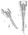
- Fig. 1 is a perspective, cross-section view of a needle with a catheter hub attachment nose having a co-molded elastomeric gasket in the exterior wall of the nose in accordance with the principles of the present invention
- Fig. 2 is a cross-section view of the needle of Fig. 1 with a catheter assembly to define a catheter insertion device;
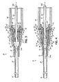
- Fig. 3 is a partial, cross-section view of a catheter insertion device with a rigid nose catheter hub attachment and a slidable needle and having co-molded elastomeric gaskets in accordance with the principles of the present invention
- Fig. 4 is a partial, cross-section view of a catheter insertion device with a split arm catheter hub attachment and a slidable needle and having co-molded elastomeric gaskets in accordance with the principles of the present invention.
- a needle device 10 having a needle housing 12, such as a flash chamber or the like, and a catheter insertion needle 14 rigidly affixed thereto so as to extend from the nose 16 of housing 12 to a sharp tip end 18. Needle 14 may optionally have a vent 19 formed proximal of tip end 18. Nose 16, alone or in conjunction with the rest of needle housing 12, defines a catheter hub attachment. Nose 16 advantageously has a tapered, circumferentially continuous exterior wall 20 such as defined by a male luer taper. Needle housing 12 is typically made by molding plastic, such as polycarbonate thermoplastic, to define a generally rigid plastic member.
- needle housing 12 may be molded and an annular elastomeric gasket 22, which may advantageously be comprised of medical grade silicone, may be co-molded with exterior wall portion 20, such as in annular recess 24 thereof, using conventional co-molding techniques.
- gasket 22 becomes an integral part of needle housing 12, and especially nose 16 thereof.
- a catheter insertion device 30 includes needle device 10 mounted to a catheter assembly 32 having a catheter hub 34 with an inner wall 36 defining a female luer taper into which male luer taper nose 16 fits and to which gasket 22 sealingly engages as at 37.
- gasket 22 is co-molded to have a slightly larger outer diameter than the inner diameter of catheter hub inner wall 36 at the area of seal 37.
- Catheter assembly 32 also includes a catheter tube 38 held to catheter hub 34 with an eyelet 39 so as to extend from catheter hub 34, with needle 14 extending through catheter tube 38 so that the sharp tip end 18 of needle 14 extends out from the beveled, distal tip end 40 of catheter tube 38. Needle 14 and tube 38 may allow blood to pass therebetween from vent 19.
- Catheter insertion device 30 may be used to install catheter tube 38 into a patient's blood vessel (not shown) in conventional manner, and needle housing 12 and catheter hub 34 may be relatively rotated as needed. Any blood (not shown) that might attempt to pass between needle 14 and catheter tube 38 will encounter the seal 37 at gasket 22 by which to forestall migration of the blood (not shown) between exterior wall 20 of catheter hub attachment nose 16 and inner wall 36 of catheter hub 34.
- Gasket 22 provides an improved and more reliable seal than would have otherwise been provided by the rigid plastic-to-plastic interfitting of nose exterior wall 20 and catheter hub inner wall 36 alone. Although not shown for sake of clarity, the latter may still be provided in addition to the seal provided by gasket 22 interacting with catheter hub inner wall 36, if desired.
- a catheter insertion device 50 includes a catheter assembly 32 like that shown in Fig. 2 (and having like-numbered parts) and a catheter hub attachment 52.
- Catheter hub attachment 52 has a distal nose 54 (similar to nose 16 shown in Figs. 1 and 2 ) with an inner wall 55 defining a passageway 56 sized to slidably receive needle 14 therethrough as indicated by arrows 56a and 56b, and an exterior, male luer slip taper wall 57 to fit within catheter hub 34.
- Distal nose 54 has co-molded elastomeric gasket 22 integrally associated with exterior wall 57 (such as in recess 24) to form the seal 37 with inner wall 36 of catheter hub 34 as described in connection with nose 16 above.
- catheter hub attachment 52 may also, alternatively or additionally, include another co-molded elastomeric gasket 58 integrally associated with the inner wall 55 of catheter hub attachment 52 (such as in annular recess 59 of wall 55).
- Gasket 58 has an entry aperture 60 to also define a seal, as at 61, against shaft surface 62 of needle 14 (which, in this embodiment need not include the vent 19) as it slides through (into or out of) passageway 56 of catheter hub attachment 52.
- gasket 58 is formed to have an inner diameter of aperture 60 slightly smaller than the nominal outer diameter of needle shaft 62.
- Gaskets 22 and 58 may be co-molded at the same time, such as by first moulding catheter hub attachment 52 of rigid plastic with one or more ports 63 (only one shown) communicating between recesses 24 and 59, followed by co-molding the elastomeric material into recess 24 and, via port(s) 63, into recess 59.
- the proximal end 64 of catheter hub attachment 52 may form, or be attached to, the distal side 65 of a needle guard or needle shield housing 66.
- Housing 66 may take on numerous forms and possibly include a wide variety of needle tipping and/or needle tip shield structures (not shown).
- such housings can include the needle guard housing of the PROTECTIV Safety I.V. Catheter being marketed by Medex, Inc., the assignee hereof, a version thereof with fluid path access as shown and described in the commonly assigned and concurrently filed U.S. Patent Application entitled “Enclosed Needle Device With Fluid Path Access", Attorney Docket No. MDXVA-103US, or housing structure to grip and/or block the needle as shown in U.S. Patent Nos.
- gasket 58 is formed in passageway 56 distal of the proximal end 64, although it will be appreciated that an elastomeric gasket could additionally or alternatively be within the proximal end 64 such as by being co-molded as a larger gasket in extension 67 of passageway 56 such as in the mouth 68 of proximal end 64.
- Gasket 58 provides an easily manufactured, reliable and tolerant seal 61 to needle 14 to thereby reduce or eliminate backflow of blood (not shown) over needle shaft 62 through passageway 56.
- catheter assembly 72 has a catheter hub 75 within inner wall 76 which may advantageously define a female luer taper slip extending from hub opening 78, and an annular rib 80 distally of proximal opening 78 thereof to define an annular space 82 distal of rib 80 for purposes to be explained hereafter.
- Catheter hub attachment 74 has a distal nose 84 which includes a pair of arms 86, 88 extending from a tapered, tubular nose segment 90 coupled to proximal end 92 (the latter being akin to proximal end 62 of Fig. 3 ).
- arms 86, 88 and/or nose segment 90 define exterior walls 94 designed to fit within catheter hub 75, with arms 86, 88 adapted to flex.
- arms 86, 88 may include a detent 96 which normally extends to an outer diametrical distance larger than the inner diameter defined at rib 80.
- the inner surfaces 98 of arms 86, 88 are normally spaced apart a distance that is only slightly larger than the outer diameter of needle shaft 62.
- Needle passageway 56 extends between inner surfaces 98 of arms 86, 88 as at passageway potion 56'.
- catheter hub attachment 74 is held to catheter hub 75 to help improve the sealing feature of gasket 22 until catheter hub attachment 74 is removed from catheter hub 75.
- housing 66 is like the needle guard housing of the PROTECTIV Safety I.V. Catheter mentioned earlier, a cooperating locking mechanism may be employed as shown and described in the commonly assigned and concurrently filed U.S. Patent Application entitled “Enclosed Needle Device with Duckbill Release Mechanism", Attorney Docket No. MDXVA-94US.
- Distal nose 84 includes integral, co-molded elastomeric gasket 22 with exterior wall 94 such as in recess 24 of tubular nose segment 90, and passageway 56 includes co-molded elastomeric gasket 58, both of which may be formed, and which operate, as described in connection with Fig. 3 .
- some prior seals such as a formed-in-place UV curable gasket, could interfere with the functioning of arms 86, 88; co-molded gasket 58 will not likely do so.
- needle 14 is placed (in the direction of arrow 56a, for example) so that tip 18 extends out from catheter tube 38.
- the exposed sharp tip 18 of needle 14 is used to pierce the skin and blood vessel of a patient (not shown) to place catheter tube 38 therein.
- Gasket 22 provides a seal against blood (not shown) attempting to migrate out of the catheter hub 34 or 75.
- Needle 14 is then withdrawn, either by pulling it out with housing 12 and catheter hub attachment 16 if needle 14 is affixed thereto ( Fig. 2 ), or by pulling needle 14 through passageway 56 and thereafter pulling catheter hub attachment 52 or 74 away from catheter hub 34 or 75 ( Figs. 3 and 4 ).
- gasket 58 reduces the risk of blood (not shown) migrating through catheter hub attachment 52 or 74. With catheter hub attachment 16, 52 or 74 removed, catheter hub 34 will be exposed for use by the medical practitioner (not shown). The needle 14 and related components may then be discarded.
- detent(s) 96 of arms 86, 88 are shown as holding behind rib 80 in space 82.
- inner wall 76 of catheter hub 75 could have an annular recess (not shown) at space 82 into which the detent 96 snaps when arms 86, 88 flex to the normal state.
- a metal needle shield clip (not shown) could be provided over needle shaft 62 and sized to fit within catheter hub 34 or 75 (the latter may require size changes to one or more of the plastic components, however) such as shown in U.S. Patent No. 6,652,486 B2 .
- gasket 22 or gasket 58 may be provided, multiple such gaskets may be defined during the co-molding process if desired.
- the invention in its broader aspects is, therefore, not limited to the specific details, representative apparatus and method, and illustrative examples shown and described.
Abstract
Description
- The present invention relates to devices which couple to catheter hubs, and more particularly, to a catheter hub attachment of a catheter insertion device.
- Over-the-needle catheters are well known in the art. In such devices, a cannula needle projects through a catheter tube with its sharp tip projecting out of the end of the tube. The sharp tip of the needle is used to pierce the skin and the blood vessel so as to carry the end of the catheter tube into the vessel. Once in place, the needle is withdrawn, leaving the catheter in place for administration or withdrawal of fluids, such as by connection with the female luer taper of the now-exposed catheter hub.
- The needle is typically supported by a hub or other housing which has a catheter hub attachment for removably attaching the housing to the catheter hub. The catheter hub attachment may be in the form of a rigid, tapered nose, such as a male slip luer, the exterior wall of which is adapted to frictionally engage against a generally, rigid inner female luer taper of the catheter hub. In some devices, in order to protect against needle sticks after withdrawal of the needle from the catheter, the needle might be slidably movable through the catheter hub attachment so that the needle may be withdrawn into a needle guard or a housing containing needle gripping and/or shielding structure. In the latter type of devices, the catheter hub attachment may still be defined by a rigid nose, but with an internal passageway for the needle to slidingly pass through. Alternatively or additionally, the catheter hub attachment nose may include a pair of flexing arms adapted to resiliently engage the inner wall of the catheter hub with the passageway also extending through the space between the arms for the needle to slide therethrough.
- One problem with the prior catheter hub attachment, however, is that they might allow for blood leakage during or after insertion of the catheter into the patient. For example, the rigid nose exterior wall portion is generally continuous in circumferential extent and sized to interfit with the inner wall of the catheter hub so as to create an annular plastic-to-plastic seal in accordance with luer standards. However, the seal is not always reliable. Moreover, the hold between the catheter hub and the attachment nose is based on friction, and so in those cases where the nose and catheter hub need to be rotated relative to one another, as sometimes arises in order to properly thread the catheter into the blood vessel, the seal may be overcome. Consequently, with rigid nose catheter hub attachments, blood might migrate between the inner wall of the catheter hub and the exterior wall of the nose, thus creating a risk of blood leakage.
- Where the nose includes the pair of arms, a proximal portion of the attachment may still define a generally rigid circumferentially continuous exterior surface for interfitting with the catheter hub inner wall for purposes of creating the seal. But that seal may also not be adequate.
- Additionally, where the catheter hub attachment is designed to allow the needle to slidingly pass therethrough, blood might backflow between the needle and the passageway. Efforts to reduce such leakage have involved relatively complex seals, such as blown-in extruded gaskets or formed-in-place UV curable and breakable seals such as shown in
U.S. Patent Nos. 5,810,785 and5,092,845 , respectively. While the foregoing are believed to create a more reliable seal between the needle and catheter hub attachment, they are not without their drawbacks. -
EPA 0875 262 discloses a catheter hub with a rigid molded plastic shuttle housing coupled thereto to define an internal passageway therethrough and through which an elongated member can slidingly pass, and an elastomeric gasket captured between the hub and the housing to create a seal around an elongated member passing through the internal passageway. -
EPA 1466 644 discloses a catheter hub attachment of a catheter insertion device comprising a generally rigid molded plastic nose having an exterior wall sized to fit within a catheter hub and a needle extending from the nose. An elastomeric plug is fitted into the catheter hub exteriorly of the exterior wall of the nose to create a seal with apportion of an internal wall of a catheter hub into which the nose is fitted. - The present invention provides an improved seal for a catheter hub attachment of a needle catheter insertion device. To that end, and in accordance with the principles of the present invention, a co-molded elastomeric gasket is integrally formed into the catheter hub attachment either at the exterior wall which is to fit within the inner wall of the catheter hub and/or in the passageway through which the needle is to slide. The elastomeric gasket material may be medical grade silicone. The elastomeric and integral nature of the co-molded gasket(s) results in a seal that is reliable, yet also is less likely to fail during relative rotation of the catheter hub attachment and the catheter hub. Moreover, co-molding the elastomeric gasket material into the otherwise generally rigid plastic of the catheter hub attachment presents many advantages over previous efforts to provide seals for catheter hub attachments.
The invention also provides a method of making a catheter hub attachment comprising molding a generally rigid plastic nose having an exterior wall sized to fit within a catheter hub and characterized by co-molding an elastomeric material into the plastic nose to define an annular resilient gasket. - By way of example, and not limitation, the co-molded elastomeric gasket in the passage is believed to provide a more reliable and tolerant seal than the prior blown-in place or formed-in place seals. The co-molded elastomeric gasket(s) also provide advantages in manufacture and cost over separately provided gaskets, such as O-rings or the like, while providing O-ring like seal advantages. Further, the gasket(s) can be formed to the catheter hub attachment with conventional co-molding techniques, thus eliminating the need for multiple, separate manufacturing steps or machines. Moreover, where both the gasket at the exterior wall and the gasket in the passageway are to be included, they may both be formed at the same time.
- In addition to the foregoing, where the catheter hub attachment includes a pair of arms, the co-molded elastomeric gasket(s) do not interfere with the operation of the arms in serving to hold the catheter hub attachment to the catheter hub in a manner that allows for easy removal of the catheter hub attachment from the catheter hub after the insertion needle has been withdrawn. Similarly, the arms help improve the hold of the catheter hub attachment to the catheter hub thereby helping maintain the seal.
- By virtue of the foregoing, there is thus provided an improved seal for a catheter hub attachment of a needle catheter insertion device. These and other objects and advantages of the present invention shall be made apparent from the accompanying drawings and the description thereof.
- The accompanying drawings, which are incorporated in and constitute a part of this specification, illustrate embodiments of the invention and, together with the general description of the invention given above and the detailed description of the embodiments given below, serve to explain the principles of the present invention.
-
Fig. 1 is a perspective, cross-section view of a needle with a catheter hub attachment nose having a co-molded elastomeric gasket in the exterior wall of the nose in accordance with the principles of the present invention; -
Fig. 2 is a cross-section view of the needle ofFig. 1 with a catheter assembly to define a catheter insertion device; -
Fig. 3 is a partial, cross-section view of a catheter insertion device with a rigid nose catheter hub attachment and a slidable needle and having co-molded elastomeric gaskets in accordance with the principles of the present invention; and -
Fig. 4 is a partial, cross-section view of a catheter insertion device with a split arm catheter hub attachment and a slidable needle and having co-molded elastomeric gaskets in accordance with the principles of the present invention. - With reference to
Fig. 1 , there is shown aneedle device 10 having aneedle housing 12, such as a flash chamber or the like, and acatheter insertion needle 14 rigidly affixed thereto so as to extend from thenose 16 ofhousing 12 to asharp tip end 18.Needle 14 may optionally have avent 19 formed proximal oftip end 18.Nose 16, alone or in conjunction with the rest ofneedle housing 12, defines a catheter hub attachment.Nose 16 advantageously has a tapered, circumferentially continuousexterior wall 20 such as defined by a male luer taper.Needle housing 12 is typically made by molding plastic, such as polycarbonate thermoplastic, to define a generally rigid plastic member. In accordance with the principles of the present invention,needle housing 12 may be molded and an annularelastomeric gasket 22, which may advantageously be comprised of medical grade silicone, may be co-molded withexterior wall portion 20, such as inannular recess 24 thereof, using conventional co-molding techniques. However, due to the co-molding,gasket 22 becomes an integral part ofneedle housing 12, and especiallynose 16 thereof. - Due to the elastomeric nature of
co-molded gasket 22,gasket 22 will have more resiliency than the rest ofnose 16 and so may be used to define, or add to, a seal. To that end, and with reference toFig. 2 , acatheter insertion device 30 includesneedle device 10 mounted to acatheter assembly 32 having acatheter hub 34 with aninner wall 36 defining a female luer taper into which maleluer taper nose 16 fits and to whichgasket 22 sealingly engages as at 37. To that end,gasket 22 is co-molded to have a slightly larger outer diameter than the inner diameter of catheter hubinner wall 36 at the area ofseal 37.Catheter assembly 32 also includes acatheter tube 38 held tocatheter hub 34 with aneyelet 39 so as to extend fromcatheter hub 34, withneedle 14 extending throughcatheter tube 38 so that thesharp tip end 18 ofneedle 14 extends out from the beveled,distal tip end 40 ofcatheter tube 38.Needle 14 andtube 38 may allow blood to pass therebetween fromvent 19.Catheter insertion device 30 may be used to installcatheter tube 38 into a patient's blood vessel (not shown) in conventional manner, andneedle housing 12 andcatheter hub 34 may be relatively rotated as needed. Any blood (not shown) that might attempt to pass betweenneedle 14 andcatheter tube 38 will encounter theseal 37 atgasket 22 by which to forestall migration of the blood (not shown) betweenexterior wall 20 of catheterhub attachment nose 16 andinner wall 36 ofcatheter hub 34. Gasket 22 provides an improved and more reliable seal than would have otherwise been provided by the rigid plastic-to-plastic interfitting of noseexterior wall 20 and catheter hubinner wall 36 alone. Although not shown for sake of clarity, the latter may still be provided in addition to the seal provided bygasket 22 interacting with catheter hubinner wall 36, if desired. - With reference to
Fig. 3 , acatheter insertion device 50 includes acatheter assembly 32 like that shown inFig. 2 (and having like-numbered parts) and acatheter hub attachment 52.Catheter hub attachment 52 has a distal nose 54 (similar tonose 16 shown inFigs. 1 and 2 ) with an inner wall 55 defining apassageway 56 sized to slidably receiveneedle 14 therethrough as indicated byarrows catheter hub 34. Distal nose 54 has co-moldedelastomeric gasket 22 integrally associated with exterior wall 57 (such as in recess 24) to form theseal 37 withinner wall 36 ofcatheter hub 34 as described in connection withnose 16 above. But,catheter hub attachment 52 may also, alternatively or additionally, include another co-molded elastomeric gasket 58 integrally associated with the inner wall 55 of catheter hub attachment 52 (such as inannular recess 59 of wall 55). Gasket 58 has anentry aperture 60 to also define a seal, as at 61, againstshaft surface 62 of needle 14 (which, in this embodiment need not include the vent 19) as it slides through (into or out of)passageway 56 ofcatheter hub attachment 52. To that end, gasket 58 is formed to have an inner diameter ofaperture 60 slightly smaller than the nominal outer diameter ofneedle shaft 62.Gaskets 22 and 58 may be co-molded at the same time, such as by first mouldingcatheter hub attachment 52 of rigid plastic with one or more ports 63 (only one shown) communicating betweenrecesses recess 24 and, via port(s) 63, intorecess 59. - The
proximal end 64 ofcatheter hub attachment 52 may form, or be attached to, thedistal side 65 of a needle guard orneedle shield housing 66.Housing 66 may take on numerous forms and possibly include a wide variety of needle tipping and/or needle tip shield structures (not shown). By way of example, such housings can include the needle guard housing of the PROTECTIV Safety I.V. Catheter being marketed by Medex, Inc., the assignee hereof, a version thereof with fluid path access as shown and described in the commonly assigned and concurrently filed U.S. Patent Application entitled "Enclosed Needle Device With Fluid Path Access", Attorney Docket No. MDXVA-103US, or housing structure to grip and/or block the needle as shown inU.S. Patent Nos. 4,762,516 ;4,747,831 ;4,978,244 ;5,215,528 ;5,322,517 ;5,328,482 ; and5,558,651 ; European Patent No.0,352,928 B2 ; and/orU.S. Patent Application Nos. 10/905,047 and10/906,171 - In the
catheter hub attachment 52 shown inFig. 3 , gasket 58 is formed inpassageway 56 distal of theproximal end 64, although it will be appreciated that an elastomeric gasket could additionally or alternatively be within theproximal end 64 such as by being co-molded as a larger gasket inextension 67 ofpassageway 56 such as in themouth 68 ofproximal end 64. Gasket 58 provides an easily manufactured, reliable and tolerant seal 61 toneedle 14 to thereby reduce or eliminate backflow of blood (not shown) overneedle shaft 62 throughpassageway 56. - With reference to
Fig. 4 , there is shown an alternatecatheter insertion device 70 havingcatheter assembly 72 andcatheter hub attachment 74.Catheter assembly 72 has a catheter hub 75 within inner wall 76 which may advantageously define a female luer taper slip extending fromhub opening 78, and anannular rib 80 distally ofproximal opening 78 thereof to define anannular space 82 distal ofrib 80 for purposes to be explained hereafter.Catheter hub attachment 74 has adistal nose 84 which includes a pair ofarms tubular nose segment 90 coupled to proximal end 92 (the latter being akin toproximal end 62 ofFig. 3 ). The outer aspects ofarms nose segment 90 defineexterior walls 94 designed to fit within catheter hub 75, witharms arms rib 80. Ascatheter hub attachment 74 is inserted into catheter hub 75,arm 86 and/orarm 88 flexes inwardly to ride overrib 80, and then flex back out to provide a weak hold ofcatheter hub attachment 74 against catheter hub inner wall 76. - Advantageously, the
inner surfaces 98 ofarms needle shaft 62.Needle passageway 56 extends betweeninner surfaces 98 ofarms needle 14 pushed distally (in the direction ofarrow 56a) so that it passes through passageway portion 56' to extend fully betweenarms 86, 88 (and advantageously to extendsharp tip end 18 out of catheter tube 38), the close fit betweenneedle shaft 62 andarms arms catheter hub attachment 74 away from catheter hub 75 is increased whileneedle shaft 62 is betweenarms shaft 62 is not present therebetween (such as by movingneedle 14 in the diameter ofarrow 56b to the position shown, for example, inFig. 4 ). Also, even with the weak forces involved withneedle 14 in the position shown inFig. 4 ,catheter hub attachment 74 is held to catheter hub 75 to help improve the sealing feature ofgasket 22 untilcatheter hub attachment 74 is removed from catheter hub 75. Wherehousing 66 is like the needle guard housing of the PROTECTIV Safety I.V. Catheter mentioned earlier, a cooperating locking mechanism may be employed as shown and described in the commonly assigned and concurrently filed U.S. Patent Application entitled "Enclosed Needle Device with Duckbill Release Mechanism", Attorney Docket No. MDXVA-94US. -
Distal nose 84 includes integral, co-moldedelastomeric gasket 22 withexterior wall 94 such as inrecess 24 oftubular nose segment 90, andpassageway 56 includes co-molded elastomeric gasket 58, both of which may be formed, and which operate, as described in connection withFig. 3 . However, some prior seals, such as a formed-in-place UV curable gasket, could interfere with the functioning ofarms - In use,
needle 14 is placed (in the direction ofarrow 56a, for example) so thattip 18 extends out fromcatheter tube 38. The exposedsharp tip 18 ofneedle 14 is used to pierce the skin and blood vessel of a patient (not shown) to placecatheter tube 38 therein.Gasket 22 provides a seal against blood (not shown) attempting to migrate out of thecatheter hub 34 or 75.Needle 14 is then withdrawn, either by pulling it out withhousing 12 andcatheter hub attachment 16 ifneedle 14 is affixed thereto (Fig. 2 ), or by pullingneedle 14 throughpassageway 56 and thereafter pullingcatheter hub attachment catheter hub 34 or 75 (Figs. 3 and 4 ). Wherepassageway 56 is provided, gasket 58 reduces the risk of blood (not shown) migrating throughcatheter hub attachment catheter hub attachment catheter hub 34 will be exposed for use by the medical practitioner (not shown). Theneedle 14 and related components may then be discarded. - By virtue of the foregoing, there is thus provided an improved seal for a catheter hub attachment of a needle catheter insertion device.
- While the present invention has been illustrated by the description of embodiments thereof, and while the embodiments have been described in considerable detail, additional advantages and modifications will readily appear to those skilled in the art. For example, detent(s) 96 of
arms rib 80 inspace 82. Alternatively or additionally, inner wall 76 of catheter hub 75 could have an annular recess (not shown) atspace 82 into which the detent 96 snaps whenarms needle shaft 62 and sized to fit withincatheter hub 34 or 75 (the latter may require size changes to one or more of the plastic components, however) such as shown inU.S. Patent No. 6,652,486 B2 . Additionally, although only one ofgasket 22 or gasket 58 may be provided, multiple such gaskets may be defined during the co-molding process if desired. The invention in its broader aspects is, therefore, not limited to the specific details, representative apparatus and method, and illustrative examples shown and described.
Claims (18)
- A catheter hub attachment of a catheter insertion device comprising a generally rigid molded plastic nose (16, 52, 84) having an exterior wall (20, 57, 94) sized to fit within a catheter hub (34, 75), wherein either (a) the nose (16, 52, 84) has a proximal end and a distal end opening and an internal passageway (56) therethrough and through which a catheter insertion needle (14) can slidingly pass into and out of the openings and an elastomeric inner gasket (58) is integrally associated with the internal passageway (56) proximal of the distal end opening so as to be an integral part of the nose (16, 52, 84), whereby to create a seal around a catheter insertion needle passing through the internal passageway and/or wherein (b) a needle (14) extends from the nose and an elastomeric outer gasket (22) is integrally associated with the exterior wall (20, 57, 94) so as to be an integral part of the nose (16, 52, 84), whereby to create a seal with a portion of an internal wall (36, 76) of a catheter hub (34, 75) into which the nose is fitted.
- A catheter hub attachment as claimed in claim 1 wherein (b), the nose includes an internal passageway (56), the needle slidingly passing through the internal passageway of the nose.
- A catheter hub attachment as claimed in claim 1 wherein (a) and a catheter insertion needle (14) is received in the internal passageway of the nose.
- A catheter hub attachment as claimed in claim 1 wherein (a) or claim 3, the nose having a proximal portion (64, 92) adapted to be coupled to a needle guard housing (66).
- A catheter hub attachment as claimed in claim 4, the inner gasket (58) being spaced distally from the proximal portion.
- A catheter hub attachment as claimed in any of claim 1 wherein (a) and claims 3 to 5, the inner gasket (58) extending from a recess (59) confronting the passageway (56).
- A catheter hub attachment as claimed in any of claim 1 wherein (a) and claims 3 to 6 further comprising an elastomeric outer gasket (22) integrally associated with the exterior wall (20, 57, 94) whereby to create a seal with a portion of an internal wall (36, 76) of a catheter hub (34, 75) into which the nose is fitted.
- A catheter hub attachment as claimed in claim 7 further comprising a port (63) communicating between the inner and outer gaskets (58, 22).
- A catheter hub attachment as claimed in any of claim 1 wherein (a) and claims 2 to 8, the nose including a pair of arms (86, 88), the arms defining a portion of the passageway (56) therebetween.
- A catheter hub attachment as claimed in any of claim 1 wherein (b) and claims 2, 7 and 8, the outer gasket (22) extending from a recess (24) in the exterior wall (20, 57, 94).
- A catheter hub attachment as claimed in any preceding claim, the nose including a generally continuous tubular taper.
- A catheter hub attachment as claimed in claim 11, the exterior wall (20, 57, 94) defining at least a portion of the tubular taper.
- A method of making a catheter hub attachment comprising molding a generally rigid plastic nose (16, 52, 84) having an exterior wall (20, 57, 94) sized to fit within a catheter hub (34, 75) and characterized by co-molding an elastomeric material into the plastic nose (16, 52, 84) to define an annular resilient gasket (22).
- A method as claimed in claim 13 wherein molding the plastic nose (16, 52, 84) includes defining a passageway (56) therethrough, and wherein co-molding the elastomeric material includes co-molding the elastomeric material into the passageway (56).
- A method as claimed in claim 13 or claim 14 wherein co-molding the elastomeric material includes co-molding the elastomeric material into the exterior wall (20, 57, 94).
- A method as claimed in claim 13 wherein molding the nose (16, 52, 84) includes defining a passageway (56) therethrough, and wherein co-molding the elastomeric material includes co-molding the elastomeric material to define a first annular resilient gasket (22) in the exterior wall and to define a second annular resilient gasket (58) in the passageway.
- A method as claimed in claim 16 wherein molding the nose (16, 52, 84) includes defining a port (63) between the exterior wall (20, 57, 94) and the passageway (56), and co-molding the elastomeric material includes passing the elastomeric material through the port (63).
- A method as claimed in any of claims 13 through 17 wherein molding the plastic nose (16, 52, 84) includes forming a pair of arms (86, 88) adapted to engage with an inner wall of a catheter hub.
Applications Claiming Priority (2)
| Application Number | Priority Date | Filing Date | Title |
|---|---|---|---|
| US11/276,155 US7736337B2 (en) | 2006-02-16 | 2006-02-16 | Sealing catheter hub attachment |
| PCT/US2007/062191 WO2007098359A1 (en) | 2006-02-16 | 2007-02-15 | Sealing catheter hub attachment |
Publications (2)
| Publication Number | Publication Date |
|---|---|
| EP1998836A1 EP1998836A1 (en) | 2008-12-10 |
| EP1998836B1 true EP1998836B1 (en) | 2010-12-01 |
Family
ID=38171115
Family Applications (1)
| Application Number | Title | Priority Date | Filing Date |
|---|---|---|---|
| EP07757036A Not-in-force EP1998836B1 (en) | 2006-02-16 | 2007-02-15 | Sealing catheter hub attachment |
Country Status (13)
| Country | Link |
|---|---|
| US (1) | US7736337B2 (en) |
| EP (1) | EP1998836B1 (en) |
| JP (1) | JP2009527286A (en) |
| AT (1) | ATE489985T1 (en) |
| AU (1) | AU2007217072B2 (en) |
| BR (1) | BRPI0707631A2 (en) |
| CA (1) | CA2637624C (en) |
| DE (1) | DE602007010910D1 (en) |
| ES (1) | ES2353560T3 (en) |
| IL (1) | IL193111A0 (en) |
| NZ (1) | NZ570238A (en) |
| PT (1) | PT1998836E (en) |
| WO (1) | WO2007098359A1 (en) |
Cited By (1)
| Publication number | Priority date | Publication date | Assignee | Title |
|---|---|---|---|---|
| US11602709B2 (en) | 2016-10-20 | 2023-03-14 | Emd Millipore Corporation | Valve protection and tube management device |
Families Citing this family (72)
| Publication number | Priority date | Publication date | Assignee | Title |
|---|---|---|---|---|
| GB0120645D0 (en) | 2001-08-24 | 2001-10-17 | Smiths Group Plc | Medico-surgical devices |
| GB0307350D0 (en) | 2003-03-29 | 2003-05-07 | Smiths Group Plc | Catheters |
| WO2007006055A2 (en) | 2005-07-06 | 2007-01-11 | Vascular Pathways Inc. | Intravenous catheter insertion device and method of use |
| US7632243B2 (en) * | 2005-08-08 | 2009-12-15 | Smiths Medical Asd, Inc. | Duckbill catheter release mechanism |
| US8403886B2 (en) | 2005-08-08 | 2013-03-26 | Smiths Medical Asd, Inc. | Needle guard clip with lip |
| US8162881B2 (en) | 2005-08-08 | 2012-04-24 | Smiths Medical Asd, Inc. | Needle guard mechanism with angled strut wall |
| US8251950B2 (en) | 2005-08-08 | 2012-08-28 | Smiths Medical Asd, Inc. | Needle guard clip with heel |
| US7597681B2 (en) * | 2005-08-08 | 2009-10-06 | Smiths Medical Asd, Inc. | Needle guard mechanism with shroud |
| US20070038187A1 (en) * | 2005-08-08 | 2007-02-15 | Albert Sean J | Needle guard mechanism with anti-rotation feature |
| JP4994775B2 (en) | 2006-10-12 | 2012-08-08 | 日本コヴィディエン株式会社 | Needle point protector |
| WO2008137956A2 (en) | 2007-05-07 | 2008-11-13 | Vascular Pathways, Inc. | Intravenous catheter insertion and blood sample devices and method of use |
| US8298180B2 (en) | 2007-11-21 | 2012-10-30 | Becton, Dickinson And Company | Safety needle guard |
| NZ585519A (en) | 2007-11-21 | 2012-10-26 | Becton Dickinson Co | A needle guard with a pivoting arm with a needle tip sensing element |
| JP5134729B2 (en) | 2008-07-01 | 2013-01-30 | エンドロジックス、インク | Catheter system |
| BRPI0915953B1 (en) | 2008-07-21 | 2021-04-13 | Becton, Dickinson And Company | MECHANICAL SEPARATOR, SEPARATION ASSEMBLY AND SEPARATING METHOD |
| EP2644274B1 (en) | 2008-07-21 | 2015-05-20 | Becton Dickinson and Company | Density phase separation device |
| CN102149472B (en) | 2008-07-21 | 2014-08-13 | 贝克顿·迪金森公司 | Density phase separation device |
| PL3879268T3 (en) | 2009-05-15 | 2023-01-09 | Becton, Dickinson And Company | Density phase separation device |
| US8323249B2 (en) | 2009-08-14 | 2012-12-04 | The Regents Of The University Of Michigan | Integrated vascular delivery system |
| US9872971B2 (en) | 2010-05-14 | 2018-01-23 | C. R. Bard, Inc. | Guidewire extension system for a catheter placement device |
| US9950139B2 (en) | 2010-05-14 | 2018-04-24 | C. R. Bard, Inc. | Catheter placement device including guidewire and catheter control elements |
| US11925779B2 (en) | 2010-05-14 | 2024-03-12 | C. R. Bard, Inc. | Catheter insertion device including top-mounted advancement components |
| US8932258B2 (en) | 2010-05-14 | 2015-01-13 | C. R. Bard, Inc. | Catheter placement device and method |
| US10384039B2 (en) | 2010-05-14 | 2019-08-20 | C. R. Bard, Inc. | Catheter insertion device including top-mounted advancement components |
| WO2011146769A2 (en) | 2010-05-19 | 2011-11-24 | Tangent Medical Technologies Llc | Integrated vascular delivery system |
| US8814833B2 (en) | 2010-05-19 | 2014-08-26 | Tangent Medical Technologies Llc | Safety needle system operable with a medical device |
| US8652104B2 (en) | 2010-06-25 | 2014-02-18 | Smiths Medical Asd, Inc. | Catheter assembly with seal member |
| US9545495B2 (en) | 2010-06-25 | 2017-01-17 | Smiths Medical Asd, Inc. | Catheter assembly with seal member |
| US8419783B2 (en) | 2010-07-07 | 2013-04-16 | Cook Medical Technologies Llc | Graft deployment assist tool |
| US8690833B2 (en) | 2011-01-31 | 2014-04-08 | Vascular Pathways, Inc. | Intravenous catheter and insertion device with reduced blood spatter |
| CN103379937B (en) | 2011-02-25 | 2016-09-07 | C·R·巴德股份有限公司 | Medical component insertion device including retractible pin |
| WO2012118901A1 (en) | 2011-03-01 | 2012-09-07 | Endologix, Inc. | Catheter system and methods of using same |
| EP2517751B8 (en) | 2011-04-27 | 2018-02-28 | Kpr U.S., Llc | Safety IV catheter assemblies |
| USD903101S1 (en) | 2011-05-13 | 2020-11-24 | C. R. Bard, Inc. | Catheter |
| EP2760521B1 (en) | 2011-09-26 | 2016-01-06 | Covidien LP | Safety iv catheter and needle assembly |
| WO2013048975A1 (en) | 2011-09-26 | 2013-04-04 | Covidien Lp | Safety catheter |
| US8834422B2 (en) | 2011-10-14 | 2014-09-16 | Covidien Lp | Vascular access assembly and safety device |
| JP6226201B2 (en) * | 2012-05-31 | 2017-11-08 | 株式会社ジェイ・エム・エス | Indwelling needle device |
| EP2926857B1 (en) * | 2012-11-30 | 2020-04-29 | Terumo Kabushiki Kaisha | Catheter |
| RU2628049C2 (en) | 2013-01-18 | 2017-08-14 | Мерит Медикал Системз, Инк. | Shock device for biopsy |
| WO2014120741A1 (en) | 2013-01-30 | 2014-08-07 | Vascular Pathways, Inc. | Systems and methods for venipuncture and catheter placement |
| US9717886B2 (en) | 2013-03-12 | 2017-08-01 | Teleflex Medical Incorporated | Safety clip for a needle |
| US11224724B2 (en) | 2013-03-12 | 2022-01-18 | Teleflex Medical Incorporated | Catheter insertion device |
| US10357635B2 (en) | 2013-03-12 | 2019-07-23 | Teleflex Medical Incorporated | Catheter insertion device |
| WO2015112484A1 (en) * | 2014-01-21 | 2015-07-30 | Merit Medical Systems, Inc. | Introducer sheath and methods |
| WO2015119940A1 (en) | 2014-02-04 | 2015-08-13 | Icu Medical, Inc. | Self-priming systems and methods |
| US9555221B2 (en) * | 2014-04-10 | 2017-01-31 | Smiths Medical Asd, Inc. | Constant force hold tip protector for a safety catheter |
| US10232146B2 (en) | 2014-09-05 | 2019-03-19 | C. R. Bard, Inc. | Catheter insertion device including retractable needle |
| US9956381B2 (en) * | 2014-09-26 | 2018-05-01 | Florida Electrophysiology Llc | Concepts for catheter control and stabilization |
| JP1527113S (en) * | 2014-10-03 | 2015-06-22 | ||
| US9694359B2 (en) | 2014-11-13 | 2017-07-04 | Becton, Dickinson And Company | Mechanical separator for a biological fluid |
| USD903100S1 (en) | 2015-05-01 | 2020-11-24 | C. R. Bard, Inc. | Catheter placement device |
| JP7016261B2 (en) | 2015-05-15 | 2022-02-21 | シー・アール・バード・インコーポレーテッド | Catheter indwelling device with extendable needle safety component |
| BR202015015333Y1 (en) * | 2015-06-24 | 2021-01-19 | Osnir Yoshime Watanabe | constructive provision introduced in needle for follicular aspiration |
| EP3139860A4 (en) | 2015-06-30 | 2018-02-07 | Endologix, Inc. | Locking assembly for coupling guidewire to delivery system |
| BR122019017170B1 (en) | 2015-08-18 | 2022-08-16 | B. Braun Melsungen Ag | CATHETER ASSEMBLY |
| GB201520043D0 (en) | 2015-11-13 | 2015-12-30 | Smiths Medical Int Ltd | Needle assemblies and methods of manufacture |
| JP7051821B2 (en) | 2016-09-12 | 2022-04-11 | シー・アール・バード・インコーポレーテッド | Blood control for catheter insertion device |
| EP3562539A4 (en) | 2016-12-27 | 2020-09-16 | Vasonics, LLC | Catheter housing |
| CA3054969A1 (en) | 2017-03-01 | 2018-09-07 | C.R. Bard, Inc. | Catheter insertion device |
| EP3568187B1 (en) | 2017-03-06 | 2021-07-07 | Smiths Medical ASD, Inc. | Blood containment for iv catheter |
| EP3568185A4 (en) * | 2017-03-06 | 2020-10-28 | Smiths Medical ASD, Inc. | Catheter insertion device with tip protector housing |
| EP3573695A4 (en) | 2017-03-06 | 2020-10-28 | Smiths Medical ASD, Inc. | Iv catheter with vein entry indication |
| CA3059619C (en) | 2017-04-13 | 2022-12-06 | Teleflex Medical Incorporated | Catheter insertion device |
| WO2019173641A1 (en) | 2018-03-07 | 2019-09-12 | Bard Access Systems, Inc. | Guidewire advancement and blood flashback systems for a medical device insertion system |
| US11338113B2 (en) * | 2018-06-07 | 2022-05-24 | Becton, Dickinson And Company | Needle position indicator |
| USD921884S1 (en) | 2018-07-27 | 2021-06-08 | Bard Access Systems, Inc. | Catheter insertion device |
| US11850377B2 (en) | 2018-12-17 | 2023-12-26 | B. Braun Melsungen Ag | Catheter assemblies and related methods |
| US11351354B2 (en) | 2019-02-20 | 2022-06-07 | Becton, Dickinson And Company | Extension tube clamp providing positive displacement |
| JP7203986B2 (en) | 2019-03-07 | 2023-01-13 | スミス メディカル エーエスディー インコーポレーテッド | Catheterization device with improved flashback response |
| US20220233816A1 (en) * | 2019-06-26 | 2022-07-28 | Smiths Medical Asd, Inc. | Catheter hub adapted to be used with multiuse blood control valve |
| BR112022003173A2 (en) | 2019-08-19 | 2022-05-17 | Becton Dickinson Co | Midline catheter placement device |
Family Cites Families (37)
| Publication number | Priority date | Publication date | Assignee | Title |
|---|---|---|---|---|
| DE3000903C1 (en) | 1980-01-11 | 1989-09-21 | Fresenius Chem Pharm Ind | Connection device for connecting cannulas, catheters or tubing |
| GB2067075B (en) | 1980-01-11 | 1983-11-23 | Fresenius Chem Pharm Ind | Connector for connecting cannulae catheters flexible tubes or the like |
| US4362150A (en) * | 1980-09-10 | 1982-12-07 | Kontron Cardiovascular Inc. | Percutaneous intra-aortic balloon apparatus |
| JPS58155867A (en) * | 1982-03-12 | 1983-09-16 | テルモ株式会社 | Drill needle and medical container with drill needle |
| US4791937A (en) * | 1986-08-19 | 1988-12-20 | Ko Pen Wang | Transendoscopic needle |
| US4762516A (en) | 1987-03-05 | 1988-08-09 | Luther Medical Products, Inc. | Assembly of needle catheter protector |
| US4832696A (en) | 1987-03-05 | 1989-05-23 | Luther Medical Products, Inc. | Assembly of needle and protector |
| US4747831A (en) | 1987-04-29 | 1988-05-31 | Phase Medical, Inc. | Cannula insertion set with safety retracting needle |
| US4950252A (en) | 1987-11-02 | 1990-08-21 | Luther Medical Products, Inc. | Single hand actuated locking safety catheter and method of use |
| US4952207A (en) | 1988-07-11 | 1990-08-28 | Critikon, Inc. | I.V. catheter with self-locating needle guard |
| US4978344A (en) | 1988-08-11 | 1990-12-18 | Dombrowski Mitchell P | Needle and catheter assembly |
| DE69023124T2 (en) | 1989-02-01 | 1996-11-14 | Sero Guard Corp | AUTOMATIC NEEDLE GUARD FOR A DISPOSABLE, HYPODERMAL SYRINGE. |
| US5000740A (en) | 1989-04-10 | 1991-03-19 | Critikon, Inc. | Catheter with needle guard |
| US5092845A (en) * | 1989-07-10 | 1992-03-03 | Critikon, Inc. | Catheter with needle gasket |
| US5407431A (en) | 1989-07-11 | 1995-04-18 | Med-Design Inc. | Intravenous catheter insertion device with retractable needle |
| IE911031A1 (en) * | 1990-04-03 | 1991-10-23 | Knutson Richard A | Closed system intravenous catheter |
| US5558651A (en) | 1990-04-20 | 1996-09-24 | Becton Dickinson And Company | Apparatus and method for a needle tip cover |
| US5085645A (en) * | 1990-08-15 | 1992-02-04 | Becton, Dickinson And Company | Apparatus and method for a catheter adapter with valve |
| US5215528C1 (en) | 1992-02-07 | 2001-09-11 | Becton Dickinson Co | Catheter introducer assembly including needle tip shield |
| JPH067487A (en) * | 1992-06-29 | 1994-01-18 | Maruman Golf Corp | Golf club head |
| US5234410A (en) * | 1992-10-23 | 1993-08-10 | Vlv Associates | Catheter assembly |
| US5458640A (en) | 1993-01-29 | 1995-10-17 | Gerrone; Carmen J. | Cannula valve and seal system |
| US5330435A (en) * | 1993-04-08 | 1994-07-19 | Vaillancourt Vincent L | Valve for a catheter assembly |
| JPH0724071A (en) | 1993-07-09 | 1995-01-27 | Terumo Corp | Blood vessel indwelling catheter |
| US5830189A (en) * | 1995-06-07 | 1998-11-03 | Johnson & Johnson Medical, Inc. | Catheter hub to nose engagement |
| GB9512531D0 (en) * | 1995-06-20 | 1995-08-23 | Boc Group Plc | Medical devices |
| US5810785A (en) | 1996-08-19 | 1998-09-22 | Johnson & Johnson Medical, Inc. | Blown-in-place blood gasket for a safety catheter |
| US5797880A (en) * | 1996-09-05 | 1998-08-25 | Becton And Dickinson And Company | Catheter and placement needle assembly with retractable needle |
| US5817058A (en) * | 1996-12-23 | 1998-10-06 | Shaw; Thomas J. | Retractable catheter introducer structure |
| US5911710A (en) | 1997-05-02 | 1999-06-15 | Schneider/Namic | Medical insertion device with hemostatic valve |
| US6595954B1 (en) * | 2000-03-13 | 2003-07-22 | Luther Research Partners, Llc | Insertion needle and soft catheter system with tip protector |
| ITBO20010497A1 (en) | 2001-07-31 | 2003-01-31 | Delta Med S R L | PROTECTION DEVICE FOR NEEDLE-CANNULA |
| US6652486B2 (en) | 2001-09-27 | 2003-11-25 | Medex, Inc. | Safety catheter |
| US8137317B2 (en) | 2002-03-15 | 2012-03-20 | Oscor Inc. | Locking vascular introducer assembly with adjustable hemostatic seal |
| JP3864925B2 (en) | 2003-04-08 | 2007-01-10 | ニプロ株式会社 | Indwelling catheter set |
| JP2005110842A (en) * | 2003-10-06 | 2005-04-28 | Jms Co Ltd | Connecting device |
| JP4173831B2 (en) * | 2004-04-20 | 2008-10-29 | 株式会社メディカルシード | Sampling device |
-
2006
- 2006-02-16 US US11/276,155 patent/US7736337B2/en not_active Expired - Fee Related
-
2007
- 2007-02-15 AU AU2007217072A patent/AU2007217072B2/en not_active Ceased
- 2007-02-15 ES ES07757036T patent/ES2353560T3/en active Active
- 2007-02-15 CA CA2637624A patent/CA2637624C/en not_active Expired - Fee Related
- 2007-02-15 BR BRPI0707631-2A patent/BRPI0707631A2/en not_active IP Right Cessation
- 2007-02-15 AT AT07757036T patent/ATE489985T1/en not_active IP Right Cessation
- 2007-02-15 EP EP07757036A patent/EP1998836B1/en not_active Not-in-force
- 2007-02-15 WO PCT/US2007/062191 patent/WO2007098359A1/en active Application Filing
- 2007-02-15 JP JP2008555487A patent/JP2009527286A/en active Pending
- 2007-02-15 DE DE602007010910T patent/DE602007010910D1/en active Active
- 2007-02-15 NZ NZ570238A patent/NZ570238A/en not_active IP Right Cessation
- 2007-02-15 PT PT07757036T patent/PT1998836E/en unknown
-
2008
- 2008-07-29 IL IL193111A patent/IL193111A0/en unknown
Cited By (1)
| Publication number | Priority date | Publication date | Assignee | Title |
|---|---|---|---|---|
| US11602709B2 (en) | 2016-10-20 | 2023-03-14 | Emd Millipore Corporation | Valve protection and tube management device |
Also Published As
| Publication number | Publication date |
|---|---|
| NZ570238A (en) | 2010-07-30 |
| ATE489985T1 (en) | 2010-12-15 |
| EP1998836A1 (en) | 2008-12-10 |
| ES2353560T3 (en) | 2011-03-03 |
| AU2007217072A1 (en) | 2007-08-30 |
| JP2009527286A (en) | 2009-07-30 |
| US20070191775A1 (en) | 2007-08-16 |
| WO2007098359A1 (en) | 2007-08-30 |
| CA2637624A1 (en) | 2007-08-30 |
| CA2637624C (en) | 2013-07-30 |
| PT1998836E (en) | 2011-01-26 |
| IL193111A0 (en) | 2009-02-11 |
| US7736337B2 (en) | 2010-06-15 |
| AU2007217072B2 (en) | 2011-05-26 |
| DE602007010910D1 (en) | 2011-01-13 |
| BRPI0707631A2 (en) | 2012-05-29 |
Similar Documents
| Publication | Publication Date | Title |
|---|---|---|
| EP1998836B1 (en) | Sealing catheter hub attachment | |
| US7658725B2 (en) | Enclosed needle device with duckbill release mechanism | |
| CN107913461B (en) | Compliant catheter adapter with autogenous cutting needle | |
| JP2009527286A5 (en) | ||
| US20190192823A1 (en) | Vascular Access Devices and Methods | |
| CN109364350B (en) | Catheter assembly for closed systems | |
| EP3027265B1 (en) | Blood control catheter valve employing actuator with flexible retention arms | |
| US20070191777A1 (en) | Enclosed Needle Device with Fluid Path Access | |
| US8251923B2 (en) | Device for introducing a catheter guide wire into a vessel | |
| CN106620943B (en) | Compliant catheter adapter and compression crown | |
| US8257313B2 (en) | Integrated septum and needle tip shield for a catheter assembly | |
| EP1457229B1 (en) | Intravenous catheter inserting device | |
| JP2022136158A (en) | Valved needle assembly, and indwelling needle assembly | |
| CN112915354B (en) | IV catheter assembly with injection port | |
| JP2019013844A (en) | Indwelling needle assembly | |
| TW202408615A (en) | Catheter securement device | |
| JP2006345916A (en) | Connector |
Legal Events
| Date | Code | Title | Description |
|---|---|---|---|
| PUAI | Public reference made under article 153(3) epc to a published international application that has entered the european phase |
Free format text: ORIGINAL CODE: 0009012 |
|
| 17P | Request for examination filed |
Effective date: 20080815 |
|
| AK | Designated contracting states |
Kind code of ref document: A1 Designated state(s): AT BE BG CH CY CZ DE DK EE ES FI FR GB GR HU IE IS IT LI LT LU LV MC NL PL PT RO SE SI SK TR |
|
| 17Q | First examination report despatched |
Effective date: 20090309 |
|
| GRAP | Despatch of communication of intention to grant a patent |
Free format text: ORIGINAL CODE: EPIDOSNIGR1 |
|
| GRAS | Grant fee paid |
Free format text: ORIGINAL CODE: EPIDOSNIGR3 |
|
| GRAA | (expected) grant |
Free format text: ORIGINAL CODE: 0009210 |
|
| AK | Designated contracting states |
Kind code of ref document: B1 Designated state(s): AT BE BG CH CY CZ DE DK EE ES FI FR GB GR HU IE IS IT LI LT LU LV MC NL PL PT RO SE SI SK TR |
|
| REG | Reference to a national code |
Ref country code: GB Ref legal event code: FG4D |
|
| REG | Reference to a national code |
Ref country code: CH Ref legal event code: EP |
|
| REG | Reference to a national code |
Ref country code: IE Ref legal event code: FG4D |
|
| REF | Corresponds to: |
Ref document number: 602007010910 Country of ref document: DE Date of ref document: 20110113 Kind code of ref document: P |
|
| REG | Reference to a national code |
Ref country code: PT Ref legal event code: SC4A Free format text: AVAILABILITY OF NATIONAL TRANSLATION Effective date: 20110118 |
|
| REG | Reference to a national code |
Ref country code: NL Ref legal event code: T3 |
|
| REG | Reference to a national code |
Ref country code: ES Ref legal event code: FG2A Effective date: 20110221 |
|
| REG | Reference to a national code |
Ref country code: SE Ref legal event code: TRGR |
|
| PG25 | Lapsed in a contracting state [announced via postgrant information from national office to epo] |
Ref country code: LT Free format text: LAPSE BECAUSE OF FAILURE TO SUBMIT A TRANSLATION OF THE DESCRIPTION OR TO PAY THE FEE WITHIN THE PRESCRIBED TIME-LIMIT Effective date: 20101201 |
|
| LTIE | Lt: invalidation of european patent or patent extension |
Effective date: 20101201 |
|
| PG25 | Lapsed in a contracting state [announced via postgrant information from national office to epo] |
Ref country code: CY Free format text: LAPSE BECAUSE OF FAILURE TO SUBMIT A TRANSLATION OF THE DESCRIPTION OR TO PAY THE FEE WITHIN THE PRESCRIBED TIME-LIMIT Effective date: 20101201 Ref country code: AT Free format text: LAPSE BECAUSE OF FAILURE TO SUBMIT A TRANSLATION OF THE DESCRIPTION OR TO PAY THE FEE WITHIN THE PRESCRIBED TIME-LIMIT Effective date: 20101201 Ref country code: LV Free format text: LAPSE BECAUSE OF FAILURE TO SUBMIT A TRANSLATION OF THE DESCRIPTION OR TO PAY THE FEE WITHIN THE PRESCRIBED TIME-LIMIT Effective date: 20101201 Ref country code: FI Free format text: LAPSE BECAUSE OF FAILURE TO SUBMIT A TRANSLATION OF THE DESCRIPTION OR TO PAY THE FEE WITHIN THE PRESCRIBED TIME-LIMIT Effective date: 20101201 Ref country code: BG Free format text: LAPSE BECAUSE OF FAILURE TO SUBMIT A TRANSLATION OF THE DESCRIPTION OR TO PAY THE FEE WITHIN THE PRESCRIBED TIME-LIMIT Effective date: 20110301 Ref country code: SI Free format text: LAPSE BECAUSE OF FAILURE TO SUBMIT A TRANSLATION OF THE DESCRIPTION OR TO PAY THE FEE WITHIN THE PRESCRIBED TIME-LIMIT Effective date: 20101201 |
|
| PG25 | Lapsed in a contracting state [announced via postgrant information from national office to epo] |
Ref country code: GR Free format text: LAPSE BECAUSE OF FAILURE TO SUBMIT A TRANSLATION OF THE DESCRIPTION OR TO PAY THE FEE WITHIN THE PRESCRIBED TIME-LIMIT Effective date: 20110302 |
|
| PG25 | Lapsed in a contracting state [announced via postgrant information from national office to epo] |
Ref country code: IS Free format text: LAPSE BECAUSE OF FAILURE TO SUBMIT A TRANSLATION OF THE DESCRIPTION OR TO PAY THE FEE WITHIN THE PRESCRIBED TIME-LIMIT Effective date: 20110401 Ref country code: EE Free format text: LAPSE BECAUSE OF FAILURE TO SUBMIT A TRANSLATION OF THE DESCRIPTION OR TO PAY THE FEE WITHIN THE PRESCRIBED TIME-LIMIT Effective date: 20101201 Ref country code: CZ Free format text: LAPSE BECAUSE OF FAILURE TO SUBMIT A TRANSLATION OF THE DESCRIPTION OR TO PAY THE FEE WITHIN THE PRESCRIBED TIME-LIMIT Effective date: 20101201 Ref country code: BE Free format text: LAPSE BECAUSE OF FAILURE TO SUBMIT A TRANSLATION OF THE DESCRIPTION OR TO PAY THE FEE WITHIN THE PRESCRIBED TIME-LIMIT Effective date: 20101201 |
|
| PG25 | Lapsed in a contracting state [announced via postgrant information from national office to epo] |
Ref country code: PL Free format text: LAPSE BECAUSE OF FAILURE TO SUBMIT A TRANSLATION OF THE DESCRIPTION OR TO PAY THE FEE WITHIN THE PRESCRIBED TIME-LIMIT Effective date: 20101201 Ref country code: RO Free format text: LAPSE BECAUSE OF FAILURE TO SUBMIT A TRANSLATION OF THE DESCRIPTION OR TO PAY THE FEE WITHIN THE PRESCRIBED TIME-LIMIT Effective date: 20101201 Ref country code: SK Free format text: LAPSE BECAUSE OF FAILURE TO SUBMIT A TRANSLATION OF THE DESCRIPTION OR TO PAY THE FEE WITHIN THE PRESCRIBED TIME-LIMIT Effective date: 20101201 |
|
| PG25 | Lapsed in a contracting state [announced via postgrant information from national office to epo] |
Ref country code: MC Free format text: LAPSE BECAUSE OF NON-PAYMENT OF DUE FEES Effective date: 20110228 |
|
| REG | Reference to a national code |
Ref country code: CH Ref legal event code: PL |
|
| PLBE | No opposition filed within time limit |
Free format text: ORIGINAL CODE: 0009261 |
|
| STAA | Information on the status of an ep patent application or granted ep patent |
Free format text: STATUS: NO OPPOSITION FILED WITHIN TIME LIMIT |
|
| PG25 | Lapsed in a contracting state [announced via postgrant information from national office to epo] |
Ref country code: LI Free format text: LAPSE BECAUSE OF NON-PAYMENT OF DUE FEES Effective date: 20110228 Ref country code: DK Free format text: LAPSE BECAUSE OF FAILURE TO SUBMIT A TRANSLATION OF THE DESCRIPTION OR TO PAY THE FEE WITHIN THE PRESCRIBED TIME-LIMIT Effective date: 20101201 Ref country code: CH Free format text: LAPSE BECAUSE OF NON-PAYMENT OF DUE FEES Effective date: 20110228 |
|
| 26N | No opposition filed |
Effective date: 20110902 |
|
| REG | Reference to a national code |
Ref country code: DE Ref legal event code: R097 Ref document number: 602007010910 Country of ref document: DE Effective date: 20110902 |
|
| PGFP | Annual fee paid to national office [announced via postgrant information from national office to epo] |
Ref country code: IE Payment date: 20130212 Year of fee payment: 7 |
|
| PG25 | Lapsed in a contracting state [announced via postgrant information from national office to epo] |
Ref country code: LU Free format text: LAPSE BECAUSE OF NON-PAYMENT OF DUE FEES Effective date: 20110215 |
|
| PGFP | Annual fee paid to national office [announced via postgrant information from national office to epo] |
Ref country code: NL Payment date: 20130209 Year of fee payment: 7 |
|
| PGFP | Annual fee paid to national office [announced via postgrant information from national office to epo] |
Ref country code: PT Payment date: 20130215 Year of fee payment: 7 |
|
| PG25 | Lapsed in a contracting state [announced via postgrant information from national office to epo] |
Ref country code: TR Free format text: LAPSE BECAUSE OF FAILURE TO SUBMIT A TRANSLATION OF THE DESCRIPTION OR TO PAY THE FEE WITHIN THE PRESCRIBED TIME-LIMIT Effective date: 20101201 |
|
| PG25 | Lapsed in a contracting state [announced via postgrant information from national office to epo] |
Ref country code: HU Free format text: LAPSE BECAUSE OF FAILURE TO SUBMIT A TRANSLATION OF THE DESCRIPTION OR TO PAY THE FEE WITHIN THE PRESCRIBED TIME-LIMIT Effective date: 20101201 |
|
| REG | Reference to a national code |
Ref country code: PT Ref legal event code: MM4A Free format text: LAPSE DUE TO NON-PAYMENT OF FEES Effective date: 20140818 |
|
| REG | Reference to a national code |
Ref country code: NL Ref legal event code: V1 Effective date: 20140901 |
|
| PG25 | Lapsed in a contracting state [announced via postgrant information from national office to epo] |
Ref country code: NL Free format text: LAPSE BECAUSE OF NON-PAYMENT OF DUE FEES Effective date: 20140901 |
|
| REG | Reference to a national code |
Ref country code: IE Ref legal event code: MM4A |
|
| PG25 | Lapsed in a contracting state [announced via postgrant information from national office to epo] |
Ref country code: PT Free format text: LAPSE BECAUSE OF NON-PAYMENT OF DUE FEES Effective date: 20140818 |
|
| PG25 | Lapsed in a contracting state [announced via postgrant information from national office to epo] |
Ref country code: IE Free format text: LAPSE BECAUSE OF NON-PAYMENT OF DUE FEES Effective date: 20140215 |
|
| REG | Reference to a national code |
Ref country code: FR Ref legal event code: PLFP Year of fee payment: 10 |
|
| PGFP | Annual fee paid to national office [announced via postgrant information from national office to epo] |
Ref country code: ES Payment date: 20160113 Year of fee payment: 10 |
|
| PGFP | Annual fee paid to national office [announced via postgrant information from national office to epo] |
Ref country code: SE Payment date: 20160211 Year of fee payment: 10 |
|
| REG | Reference to a national code |
Ref country code: FR Ref legal event code: PLFP Year of fee payment: 11 |
|
| REG | Reference to a national code |
Ref country code: SE Ref legal event code: EUG |
|
| PG25 | Lapsed in a contracting state [announced via postgrant information from national office to epo] |
Ref country code: SE Free format text: LAPSE BECAUSE OF NON-PAYMENT OF DUE FEES Effective date: 20170216 |
|
| REG | Reference to a national code |
Ref country code: FR Ref legal event code: PLFP Year of fee payment: 12 |
|
| PGFP | Annual fee paid to national office [announced via postgrant information from national office to epo] |
Ref country code: GB Payment date: 20180214 Year of fee payment: 12 Ref country code: DE Payment date: 20180130 Year of fee payment: 12 |
|
| PGFP | Annual fee paid to national office [announced via postgrant information from national office to epo] |
Ref country code: IT Payment date: 20180221 Year of fee payment: 12 Ref country code: FR Payment date: 20180111 Year of fee payment: 12 |
|
| REG | Reference to a national code |
Ref country code: ES Ref legal event code: FD2A Effective date: 20180625 |
|
| PG25 | Lapsed in a contracting state [announced via postgrant information from national office to epo] |
Ref country code: ES Free format text: LAPSE BECAUSE OF NON-PAYMENT OF DUE FEES Effective date: 20170216 |
|
| REG | Reference to a national code |
Ref country code: DE Ref legal event code: R119 Ref document number: 602007010910 Country of ref document: DE |
|
| GBPC | Gb: european patent ceased through non-payment of renewal fee |
Effective date: 20190215 |
|
| PG25 | Lapsed in a contracting state [announced via postgrant information from national office to epo] |
Ref country code: DE Free format text: LAPSE BECAUSE OF NON-PAYMENT OF DUE FEES Effective date: 20190903 Ref country code: GB Free format text: LAPSE BECAUSE OF NON-PAYMENT OF DUE FEES Effective date: 20190215 |
|
| PG25 | Lapsed in a contracting state [announced via postgrant information from national office to epo] |
Ref country code: IT Free format text: LAPSE BECAUSE OF NON-PAYMENT OF DUE FEES Effective date: 20190215 Ref country code: FR Free format text: LAPSE BECAUSE OF NON-PAYMENT OF DUE FEES Effective date: 20190228 |