EP1998573A2 - Stereoscopic display and phase different plate - Google Patents
Stereoscopic display and phase different plate Download PDFInfo
- Publication number
- EP1998573A2 EP1998573A2 EP08153918A EP08153918A EP1998573A2 EP 1998573 A2 EP1998573 A2 EP 1998573A2 EP 08153918 A EP08153918 A EP 08153918A EP 08153918 A EP08153918 A EP 08153918A EP 1998573 A2 EP1998573 A2 EP 1998573A2
- Authority
- EP
- European Patent Office
- Prior art keywords
- eye image
- light
- image
- phase differential
- left eye
- Prior art date
- Legal status (The legal status is an assumption and is not a legal conclusion. Google has not performed a legal analysis and makes no representation as to the accuracy of the status listed.)
- Withdrawn
Links
Images


Classifications
-
- H—ELECTRICITY
- H04—ELECTRIC COMMUNICATION TECHNIQUE
- H04N—PICTORIAL COMMUNICATION, e.g. TELEVISION
- H04N13/00—Stereoscopic video systems; Multi-view video systems; Details thereof
- H04N13/30—Image reproducers
- H04N13/332—Displays for viewing with the aid of special glasses or head-mounted displays [HMD]
- H04N13/337—Displays for viewing with the aid of special glasses or head-mounted displays [HMD] using polarisation multiplexing
-
- G—PHYSICS
- G02—OPTICS
- G02B—OPTICAL ELEMENTS, SYSTEMS OR APPARATUS
- G02B30/00—Optical systems or apparatus for producing three-dimensional [3D] effects, e.g. stereoscopic images
- G02B30/20—Optical systems or apparatus for producing three-dimensional [3D] effects, e.g. stereoscopic images by providing first and second parallax images to an observer's left and right eyes
- G02B30/22—Optical systems or apparatus for producing three-dimensional [3D] effects, e.g. stereoscopic images by providing first and second parallax images to an observer's left and right eyes of the stereoscopic type
- G02B30/25—Optical systems or apparatus for producing three-dimensional [3D] effects, e.g. stereoscopic images by providing first and second parallax images to an observer's left and right eyes of the stereoscopic type using polarisation techniques
-
- G—PHYSICS
- G02—OPTICS
- G02B—OPTICAL ELEMENTS, SYSTEMS OR APPARATUS
- G02B30/00—Optical systems or apparatus for producing three-dimensional [3D] effects, e.g. stereoscopic images
- G02B30/20—Optical systems or apparatus for producing three-dimensional [3D] effects, e.g. stereoscopic images by providing first and second parallax images to an observer's left and right eyes
- G02B30/26—Optical systems or apparatus for producing three-dimensional [3D] effects, e.g. stereoscopic images by providing first and second parallax images to an observer's left and right eyes of the autostereoscopic type
- G02B30/27—Optical systems or apparatus for producing three-dimensional [3D] effects, e.g. stereoscopic images by providing first and second parallax images to an observer's left and right eyes of the autostereoscopic type involving lenticular arrays
-
- G—PHYSICS
- G02—OPTICS
- G02B—OPTICAL ELEMENTS, SYSTEMS OR APPARATUS
- G02B30/00—Optical systems or apparatus for producing three-dimensional [3D] effects, e.g. stereoscopic images
- G02B30/20—Optical systems or apparatus for producing three-dimensional [3D] effects, e.g. stereoscopic images by providing first and second parallax images to an observer's left and right eyes
- G02B30/26—Optical systems or apparatus for producing three-dimensional [3D] effects, e.g. stereoscopic images by providing first and second parallax images to an observer's left and right eyes of the autostereoscopic type
- G02B30/30—Optical systems or apparatus for producing three-dimensional [3D] effects, e.g. stereoscopic images by providing first and second parallax images to an observer's left and right eyes of the autostereoscopic type involving parallax barriers
Abstract
Description
- The present invention relates to a stereoscopic display and a phase differential plate. Particularly, the present invention relates to a stereoscopic display and a phase differential plate being capable of reducing crosstalk.
- A stereoscopic image display apparatus that enables a right eye image and a left eye image to enter into the right eye and the left eye of a viewer, respectively by utilizing parallax of the right eye and the left eye has been known as disclosed, for example, in 1)Japanese Patent No.
3192994 3258996 - However, light spreads and reflects from a plane having different refractive index, so that a part of image light exiting from the liquid crystal panel is reflected on the surface of the parallax barrier on the liquid crystal panel side, and then, the reflected light is further reflected on the liquid crystal panel and incident on the parallax barrier again. In this case, a part of the light being incident on again is incident on a pixel adjacent to the pixel of the opposed parallax barrier. Therefore, an effect that the right eye image is separated for the left eye at the parallax barrier and the right eye image which has been separated for the left eye is incident on the left eye of a viewer, a so called cross talk occurs.
- Here, it has been described that an antireflective coating is provided on the surface of a polarizing plate of the liquid crystal panel in the above described patent documents 1) and 2). However, the coating is a glare-proof film formed by depositing such as MgF2 on a glass substrate, and scatters the incident light. Therefore, the reflected and scattered light is incident on the parallax barrier again, and rather the crosstalk may be increased.
- Accordingly, it is an advantage of the invention to provide a stereoscopic display and a phase differential plate which are capable of solving the above-mentioned problem. This advantage may be achieved through the combination of features described in independent claims of the invention. Dependent claims thereof specify preferable embodiments of the invention.
- Thus, a first aspect of the present invention provides a stereoscopic display including: an image displaying section that generates a right eye image and a left eye image and emits the same; and a phase differential plate disposed on an exit side of the image displaying section that orthogonalizes to each other or rotates reversely the polarizing directions of the right eye image and the left eye image which are incident from the image displaying section and emits the same. The phase differential plate is disposed on the image displaying section side and has an image light-antireflective film that prevents the right eye image and the left eye image from reflecting from the image displaying section.
- A second aspect of the present invention provides a phase differential plate disposed on the exit side of an image displaying section which generates a right eye image and a left eye image and emits the same. The phase differential plate includes: a phase differential section that orthogonalizes to each other or rotates reversely the polarizing directions of the right eye image and the left eye image which are incident from the image displaying section; and an image light-antireflection film disposed on the image displaying section side of the phase differential section that prevents the right eye image light and the left eye image light from reflecting from the image displaying section.
- Here, all necessary features of the present invention are not listed in the summary of the invention. The sub-combinations of the features may become the invention.
-
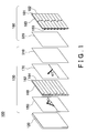
Fig.1 is an exploded perspective view showing astereoscopic display 100; -
Fig.2 is a schematic diagram showing a usage state of thestereoscopic display 100; -
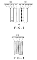
Fig.3 is a partial enlarged side view showing adisplay panel 130 and a phasedifferential plate 180; -
Fig.4 is an enlarged side view showing a part of an outside light-antireflection film 310; -
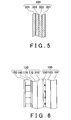
Fig.5 is an enlarged side view showing a part of an image light-antireflection film 320; -
Fig.6 is an enlarged side view showing a part of thestereoscopic display 100 according to another embodiment; and -
Fig.7 is an exploded perspective view showing anotherstereoscopic display 101. - Hereinafter, the present invention will now be described through preferred embodiments. The embodiments do not limit the invention according to claims and all combinations of the features described in the embodiments are not necessarily essential to means for solving the problems of the invention.
-
Fig.1 is an exploded perspective view showing astereoscopic display 100 manufactured by a manufacturing method according to the present embodiment. Thestereoscopic display 100, which is an example of an image displaying section, includes alight source 120, adisplay panel 130 and a phasedifferential plate 180 in the described order as shown inFig.1 . Thedisplay panel 130 includes a polarizingplate 150, animage generating section 160, a polarizingplate 170 and an outside light-antireflection film 310. The phasedifferential plate 180 includes an image light-antireflection film 320 and a phasedifferential section 183. Aviewer 500 described later views a stereoscopic image displayed on thestereoscopic display 100 from right side of the phasedifferential plate 180 inFig.1 . - The
light source 120 is arranged on the innermost of thestereoscopic display 100 from the viewpoint of theviewer 500 and emits a white non-polarized light to one surface of the polarizingplate 150 in using thestereoscopic display 100. Here, thelight source 120 is a surface illuminant in the present embodiment, however, thelight source 120 may be a combination of such as a point light source and a condenser lens instead of the surface illuminant. An example of the condenser lens is a Fresnel lenssheet. - The polarizing
plate 150 is provided on theimage generating section 160 on thelight source 120 side. The polarizingplate 150 has a transmission axis and a absorption axis orthogonalizied to the transmission axis, and when non-polarized light emitted from thelight source 120 is incident thereon, transmits light having the polarization axis in parallel with the transmission axis direction among the non-polarized light but blocks light having the polarization axis in parallel with the absorption axis direction. Here, the polarization axis direction is a direction to which light oscillates in the electric field. The transmission axis direction of the polarizingplate 150 is the direction toward the upper right having the angle of 45 degrees with the horizontal direction when theviewer 500 views thestereoscopic display 100 shown as an arrow inFig.1 . - The
image generating section 160 has right eyeimage generating regions 162 and left eyeimage generating regions 164. Each of the right eyeimage generating regions 162 and the left eyeimage generating regions 164 is obtained by dividing theimage generating section 160 by the horizontal direction, and a plurality of right eyeimage generating regions 162 and left eyeimage generating regions 164 are alternately arranged in the vertical direction as shown inFig.1 . - In using the
stereoscopic display 100, a right eye image is generated in each right eyeimage generating region 162 and a left eye image is generated in each left eyeimage generating region 164 in theimage generating section 160, respectively. At this time, light transmitted through the polarizingplate 150 is incident on the right eyeimage generating region 162 and the left eyeimage generating region 164 in theimage generating section 160, and then, the light transmitted through the right eyeimage generating region 162 becomes an image light of the right eye image (hereinafter referred to as a right eye image light) and the light transmitted through the left eyeimage generating region 164 becomes an image light of the left eye image (hereinafter referred to as a left eye image light). - Here, each of the right eye image light transmitted through the right eye
image generating region 162 and the left eye image light transmitted through the left eyeimage generating region 164 is linear polarized light having the polarization axis in a specified direction. Here, each of the polarization axes in the specified direction may be in the same direction each other. For example, each polarization axis is in the same direction as that of the transmission axis of the polarizingplate 170 described later inFig.1 . In such image generatingsection 160, a plurality of small cells are arranged in a matrix in a plane in the horizontal direction and the vertical direction, for example, and a LCD (liquid crystal display) in which liquid crystal is sealed in each cell sandwiched between oriented films is used. Each cell is electrically driven in the LCD, so that each cell switches between a state that the light is transmitted therethrough without changing the direction of the polarization axis and a state that the light is transmitted therethrough with rotating the direction of the polarization axis by 90 degrees. - The polarizing
plate 170 is provided in theimage generating section 160 on theviewer 500 side. When the right eye image light transmitted through the right eyeimage generating region 162 and the left eye image light transmitted through the left eyeimage generating region 164 are incident thereon, the polarizingplate 170 transmits the light of which polarization axis is in parallel with the transmission axis but blocks the light of which polarization axis is in parallel with the absorption axis among the incident lights. Here, the direction of the transmission axis of the polarizingplate 170 is 45 degrees upper left direction from the horizontal direction when theviewer 500 views thestereoscopic display 100 shown as the arrow inFig.1 . - The phase
differential plate 180 includes a phasedifferential section 183, alight blocking section 190 and an image light-antireflection film 320.
The phasedifferential section 183 includes first polarizingregions 181 and second polarizingregions 182. The size and the position for each of the first polarizingregions 181 and each of the second polarizingregions 182 in the phasedifferential plate 180 are corresponding to those of the right eyeimage generating region 162 and the left eyeimage generating region 164 in theimage generating section 160 as shown inFig.1 . Therefore, in using thestereoscopic display 100, the right eye image light transmitted through the right eyeimage generating region 162 is incident on the first polarizingregion 181 and the left eye image light transmitted through the left eyeimage generating region 164 is incident on the second polarizingregion 182. In addition, thelight blocking section 190 is provided on each boundary between the firstpolarizing regions 181 and the secondpolarizing regions 182 on the surface facing theimage displaying section 130 of the phase differential section183. Thelight blocking section 190 absorbs and blocks the image light over the boundary and incident on the firstpolarizing region 181 among the left eye image light to be incident on the secondpolarizing region 182 adjacent to the firstpolarizing region 181 in the phasedifferential section 183. In the same way, thelight blocking section 190 absorbs and blocks the image light over the boundary and incident on the secondpolarizing region 182 among the right eye image light to be incident on the firstpolarizing region 181 adjacent to the secondpolarizing region 182 in the phasedifferential section 183. Thus, thelight blocking section 190 is provided on each boundary on the phasedifferential section 183, so that cross talk is less likely to occur in the right eye image light and the left eye image light emitted from thestereoscopic display 100.
In addition, an adhesive resin is applied to eachlight blocking section 190 to attach the image light-antireflection film 320 thereto. The refractive index of the resin is about 1.3. Here, the image light-antireflection film 320 will be described later. - The first
polarizing region 181 does not rotate the polarization axis of the incident right eye image light but directly transmits therethrough. Meanwhile, the secondpolarizing region 182 rotates the polarization axis of the incident left eye image light to the direction orthogonalized to the polarization axis of the right eye image light incident on the firstpolarizing region 181. Therefore, the direction of the polarization axis of the right eye image light transmitted through the firstpolarizing region 181 and that of the polarization axis of the left eye image light transmitted through the secondpolarizing region 182 are orthogonalized to each other shown as the arrows inFig.1 . Here, the arrows of the phasedifferential plate 180 shown inFig.1 indicate the polarization axes of the polarized light transmitted through the phasedifferential plate 180. A transparent glass or resin is used for each firstpolarizing region 181, and a half wave retarder having an optical axis having the angle of 45 degrees with the direction of the polarization axis of the incident left eye image light is used for each secondpolarizing region 182, for example. The direction of the optical axis of the secondpolarizing region 182 is the horizontal direction or the vertical direction in the embodiment shown inFig.1 . Here, the optical axis means either the phase advance axis or the phase delay axis when light is transmitted through the secondpolarizing region 182. -
Fig.2 is a schematic diagram showing a usage state of thestereoscopic display 100. Viewing a stereoscopic image through thestereoscopic display 100, theviewer 500 views the right eye image light and the left eye image light projected from thestereoscopic display 100 with apolarized glasses 200 as shown inFig.2 . When theviewer 500 wears thepolarized glasses 200, a right eyeimage transmitting section 232 is disposed at the position for aright eye 512 side and a left eyeimage transmitting section 234 is disposed at the position for aleft eye 514 side of theviewer 500. Each of the right eyeimage transmitting section 232 and the left eyeimage transmitting section 234 is a polarizing lens having a specified transmission axis direction different from each other and fixed to a frame of thepolarized glasses 200. - The right eye
image transmitting section 232 is a polarizing plate of which transmission axis direction is the same as that of the right eye image light transmitted through the firstpolarizing region 181 and of which absorption axis direction is orthogonalized to the transmission axis direction. Meanwhile, the left eyeimage transmitting section 234 is a polarizing plate of which transmission axis direction is the same as that of the left eye image light transmitted through the secondpolarizing region 182 and of which absorption axis direction is orthogonalized to the transmission axis direction. For each of the right eyeimage transmitting section 232 and the left eyeimage transmitting section 234, a polarizing lens to which a polarizing film obtained by uniaxially drawing a film impregnating dichromatic dye is attached is used, for example. - Viewing a stereoscopic image through the
stereoscopic display 100, theviewer 500 views thestereoscopic display 100 with thepolarized glasses 200 as described above within a range in which the right eye image light and the left eye image light transmitted through the firstpolarizing region 181 and the secondpolarizing region 182, respectively in the phasedifferential plate 180 are emitted, so that theright eye 512 can view only the right eye image light and theleft eye 514 can view only the left eye image light. Therefore, theviewer 500 can perceive the right eye image light and left eye image light as a stereoscopic image. -
Fig.3 is an enlarged side view showing adisplay panel 130 and a phasedifferential plate 180. Thedisplay panel 130 supports thepolarizing plate 150,image generating section 160 and thepolarizing plate 170 which are arranged in order from thelight source 120 side and has aglass substrate 172 which protects them. In addition, thedisplay panel 130 is disposed on the exit side from which an image light is emitted of theglass substrate 172, i.e. thedifferential plate 180 side and has an outside light-antireflection film 310 that prevents an outside light from reflecting. The outside light-antireflection film 310 is a single layer film or a multilayer film having the refractive index which is medium index of those of theglass substrate 172 and air. Here, if the antireflection film is a multilayer film, it is preferred that layers of the film are laminated such that the refractive index is decreased in the direction from theglass substrate 172 to the air. - The phase
differential plate 180 has aglass substrate 184 that supports the phasedifferential section 183 and protects them. In addition, the phasedifferential plate 180 has an image light-antireflection film 320 disposed on the image light-incident side of the phase differential section 183 (thedisplay panel 130 side) that prevents an image light from reflecting from thedisplay panel 130, and an outside light-antireflection film 340 disposed on an image light-exit side of theglass substrate 184 that prevents an outside light from reflecting. The image light-antireflection film 320 is a single layer or a multilayer film having the refractive index which is medium index of those of the phasedifferential section 183 and air. Here, if the image light-antireflection film 320 is a multilayer film, it is preferred that layers of the film are laminated such that the refractive index is decreased in the direction from the phasedifferential section 183 to the air. In the same way, the outside light-antireflection film 340 is a single layer or a multilayer film having the refractive index which is medium index of those of theglass substrate 184 and air. Here, if the outside light-antireflection film 340 is a multilayer film, it is preferred that layers of the film are laminated such that the refractive index is decreased in the direction from theglass substrate 184 to the air. In the embodiment shown inFig.3 , thedisplay panel 130 and the phasedifferential plate 180 are separated via agap 342. -
Fig.4 is an enlarged side view showing a part of an outside light-antireflection film 310. The outside light-antireflection film 310 includes atransparent resin substrate 311, ahard court 312, a highrefractive index layer 313 and a lowrefractive index layer 314 in the order from theglass substrate 172 side to thegap 342 side. For example, thetransparent resin substrate 311 has the refractive index of 1.49 and the thickness of 80µm, thehard court 312 has the refractive index of 1.49 and the thickness of 1µm, the highrefractive index layer 313 has the refractive index of 1.67 and the thickness of 100nm, and the lowrefractive index layer 314 has the refractive index of 1.43 and the thickness of 105nm. The outside light-antireflection film 310 may be formed independent of theimage generating section 160 and theglass substrate 172 and attached to theglass substrate 172, or theglass substrate 172 may be directly coated with the outside light-antireflection film 310. Thereby even if thedisplay panel 130 is used without the phasedifferential plate 180, an outside light is prevented from reflecting on thedisplay panel 130, so that theviewer 500 can view a clear image. -
Fig.5 is an enlarged side view showing a part of an image light-antireflection film 320. The image light-antireflection film 320 includes atransparent resin substrate 321, ahard court 322, a highrefractive index layer 323 and a lowrefractive index layer 324 in the order from the phasedifferential section 183 side to thegap 342 side. For example, the image light-antireflection film 320 may have the same configuration as the outside light-antireflection film 310. - Here, crosstalk may occur due to the light reflected between the
display panel 130 and thephase difference plate 180. Most of the right eye image light emitted from a specified right eyeimage generating region 162 of thedisplay panel 130 is incident on the firstpolarizing region 181 of the phasedifferential plate 180 which faces thedisplay panel 130. However, the light spreads and reflects from a plane having the different refractive index. Therefore, a part of light emitted from the right eyeimage generating region 162 reflects from the phasedifferential plate 180 and the reflected light further reflects from thedisplay panel 130, and then, the further reflected light is incident on the secondpolarizing region 182 adjacent to the first polarizinglight region 181, thereby crosstalk occurs. Thus, the image light-antireflection film 320 is provided on the incident side of the phasedifferential plate 180 on which an image light is incident in the present embodiment. Thereby the image light incident on the phasedifferential plate 180 from thedisplay panel 130 is prevented from reflecting to reduce crosstalk generated between the firstpolarizing regions 181 and the secondpolarizing region 182 adjacent to each other. In this case, if the outside light-anti reflection film 310 of thedisplay panel 130 and the image light-antireflection film 320 of the phasedifferential plate 180 are partially in contact with each other, an optical interference pattern could occur. Therefore, it is preferred that the outside light-antireflection film 310 and the image light-antireflection film 320 are spaced from each other via thegap 342. A method for spacing the outside light-antireflection film 310 and the image light-antireflection film 320 from each other may include: spraying liquid that is prepared by dispersing in organic solvent spacer material such as silica beads or the like of a few to tens of microns in diameter onto a surface of the outside light-antireflection film 310 or the image light-antireflection film 320 with a sprayer or the like; evaporating the solvent; and then coupling them with each other. - The outside light-
antireflection film 340 of the phasedifferential plate 180 may have the same configuration as the image light-antireflection film 320 shown inFig.4 . The outside light-antireflection film 340 may be formed independent of the phasedifferential section 183 and theglass substrate 184 and attached to theglass substrate 184, or theglass substrate 184 may be directly coated with the outside lightanti-reflection film 340. Thereby when the phasedifferential plate 180 is disposed on the exit side of thedisplay panel 130, an outside light is prevented from reflecting on thephase difference plate 180, so that theviewer 500 can view a clear image. - A crosstalk value of the
stereoscopic display 100 having the components shown in Table 1 is measured. In Table 1, each circle in the column indicates that each of thedisplay panel 130 and the phasedifferential plate 180 has the component. Each blank column indicates that each of thedisplay panel 130 and the phasedifferential plate 180 does not have the component. Thestereoscopic display 100 of Example 1 includes the outside light-antireflection film 310, the image light-antireflection film 320 and thelight blocking section 190. Here, the crosstalk value is calculated as follows by using Cn defined by the following (1)-(3).


- Here, n indicates n-th screen region when the screen region of the
stereoscopic display 100 is divided into N. BL indicates luminance at viewing the left eye image light through the left eyeimage transmission section 234 provided that both of the right eye image light and the left eye image light are black in n-th screen region. LwL indicates luminance at viewing the image light through the left eyeimage transmission section 234 provided that the right eye image light is black and the left eye image light is white in n-th screen region. RwL indicates luminance at viewing the image light through the left eyeimage transmission section 234 provided that the right eye image light is white and the left eye image light is black in n-th screen region. In the same way, BR indicates luminance at viewing the image light through the right eyeimage transmission section 232 provided that both of the right eye image light and the left eye image light are black in n-th screen region. LwR indicates luminance at viewing the image light through the right eyeimage transmission section 232 provided that the right eye image light is black and the left eye image light is white in n-th screen region. RwR indicates luminance at viewing the image light through the right eyeimage transmission section 232 provided that the right eye image light is white and the left eye image light is black in n-th screen region. The viewing position is away from the center of the screen of thestereoscopic display 100 of 24-inch by about 700-1000mm. Under this state, crosstalk value C for the whole screen is measured by dividing the screen region into nine, measuring Cn for each image region n and averaging the same.<Table 1> EXAMPLE NO. DISPLAY PANEL 130PHASE SHIFT PLATE 180RESULT OUTSIDE LIGHT- ANTIREFLECTION FILM 310GLARE- PROOF FILM IMAGE LIGHT- ANTIREFLECTION FILM 320LIGHT BLOCKING SECTION 190OUTSIDE LIGHT- ANTIREFLECTION FILM 340CROSSTALK VALUE (%) DETERMINATION OF EFFECT EXAMPLE 1 ○ ○ ○ 0.4~0.9 ⊚ EXAMPLE 2 ○ ○ ○ ○ 0.3~0.7 ⊚ EXAMPLE 3 ○ ○ 0.7~1.3 ○ EXAMPLE 4 ○ ○ ○ 2.1~2.9 Δ EXAMPLE 5 ○ ○ 0.7~1.4 ○ COMPARATIVE EXAMPLE 1 ○ ○ 3.8~4.4 × - The
stereoscopic display 100 of Example 2 has the same configuration as thestereoscopic display 100 of the Example 1 except for further including an outside light-antireflection film 340. - The
stereoscopic display 100 of Example 3 has the same configuration as thestereoscopic display 100 of the Example 1 except for not including the outside light-antireflection film 310. - The
stereoscopic display 100 of Example 4 has the same configuration as thestereoscopic display 100 of the Example 1 except for including a glare-proof film instead of the outside light-antireflection film 310. The glare-proof film disperses a reflected light and is formed by providing a MgF2 film having the refractive index of 1.38 on both sides of the glass substrate. - The
stereoscopic display 100 of Example 5 has the same configuration as thestereoscopic display 100 of the Example 1 except for not including thelight blocking section 190. - In the Comparative example 1, the
stereoscopic display 100 having the same configuration as thestereoscopic display 100 of the Example 1 except for not including the image light-antireflection film 320 is used. - Comparing the crosstalk value of the Examples 1-5 with the crosstalk value of the Comparative example 1 shown in Table 1, it is understood that the crosstalk value is reduced by providing the image light-
antireflection film 320 on the surface of the phasedifferential plate 180 which faces thedisplay panel 130. Moreover, it is understood that the crosstalk value is further reduced by providing the outside light-antireflection film 310 on the surface of thedisplay panel 130 which faces the phasedifferential plate 180. In addition, it is understood that preferably any glare-proof film is not provided on the surface of thedisplay panel 130 which faces the phasedifferential plate 180. -
Fig.6 is an enlarged side view showing a part of thestereoscopic display 100 according to another embodiment. In thestereoscopic display 100 shown inFig.6 , the components the same as those of thestereoscopic display 100 shown inFig.1-Fig.5 have the same reference numerals as thestereoscopic display 100 shown inFig.1-Fig.5 , so that the description is omitted. - The
stereoscopic display 100 shown inFig.6 includes aresin 350 instead of the image light-antireflection film 320 of thestereoscopic display 100 shown inFig.1-Fig.5 . An image light-antireflection film of thestereoscopic display 100 shown inFig.6 is formed by filling the gap between theglass substrate 184 of the phasedifferential plate 180 and the outside light-antireflection film 310 of thedisplay panel 130 with theresin 350. Thereby the number of components can be reduced. An example of theresin 350 is adhesive having the refractive index of about 1.3. In addition, even if there is nogap 342, any optical interference pattern does not occur, and further, the phasedifferential plate 180 can be brought close to thedisplay panel 130 without generating an optical interference pattern. Therefore, crosstalk can be further reduced. -
Fig.7 is an exploded perspective view showing anotherstereoscopic display 101 manufactured by the manufacturing method according to the present embodiment. In thestereoscopic display 101 shown inFig.7 , the components the same as those of the above-describedstereoscopic display 100 have the same reference numerals as thestereoscopic display 100, so that the description is omitted. Thestereoscopic display 101 includes a phasedifferential section 185 instead of the phasedifferential section 183 of the above-describedstereoscopic display 100 as shown inFig.7 . The phasedifferential section 185 includes firstpolarizing regions 186 and secondpolarizing regions 187. Here, both of the firstpolarizing regions 186 and the secondpolarizing regions 187 are quarter wave retarders, and each optical axis thereof is orthogonalized to each other. The position and the size of each of the firstpolarizing regions 186 and the secondpolarizing regions 187 of the phasedifferential section 185 are corresponding to those of the right eyeimage generating region 162 and the left eyeimage generating region 164 of theimage generating section 160 as well as those of the firstpolarizing region 181 and the secondpolarizing region 182 of the phasedifferential section 183. Therefore, the right eye image light transmitted through the right eyeimage generating region 162 is incident on the firstpolarizing region 186 and the left eye image light transmitted through the left eyeimage generating region 164 is incident on the secondpolarizing region 187 in using thestereoscopic display 101. - The phase
differential section 185 emits the incident lights as circularly polarized lights of which polarization axes are rotated in the direction opposite to each other. For example, the firstpolarizing region 186 emits the incident light as a clockwise circularly polarized light, and the secondpolarizing region 187 emits the incident light as a counterclockwise polarized light. Here, the arrows of the phasedifferential section 185 inFig.7 indicate the rotating direction of the polarized light through the phasedifferential section 185. A quarter wave retarder having the horizontal optical axis is used for each firstpolarizing region 186, and a quarter wave retarder having the vertical optical axis is used for each secondpolarizing region 187, for example. - Further, as shown in
Fig.1 , an image light-antireflection film 320 is provided on the surface of the phasedifferential section 185 which faces thedisplay panel 130 in the phasedifferential plate 180, and an outside light-antireflection film 310 is provided on the surface of thepolarizing plate 170 which faces the phasedifferential plate 180 in thedisplay panel 130. Thereby the image light incident on the phasedifferential plate 180 from thedisplay panel 130 can be prevented from reflecting, and the crosstalk occurring between the firstpolarizing region 186 and the secondpolarizing region 187 adjacent to each other can be reduced as well as thestereoscopic display 100 shown inFig.1 . - In order to view the
stereoscopic display 101 having the phasedifferential section 185 shown inFig.7 , theviewer 500 wears polarized glasses (not shown in the figure) including quarter wave retarders and polarizing lenses which are disposed at the positions for theright eye 512 and theleft eye 514, respectively. The optical axis of the quarter wave retarder disposed at the position for theright eye 512 side of theviewer 500 is in the horizontal direction. Meanwhile, the optical axis of the quarter wave retarder disposed at the position for theleft eye 514 side of theviewer 500 is in the vertical direction. In addition, the transmission axis direction of each of the polarizing lens disposed at the position for theright eye 512 and the polarizing lens disposed at the position for theleft eye 514 of theviewer 500 has the angle of 45 degrees to the right from the viewpoint of theviewer 500, and the absorption axis direction is orthogonalized to the transmission direction. - In the case that the
viewer 500 views thestereoscopic display 101 with the polarized glasses, when a circularly polarized light of which polarization axis is rotated clockwise from the view point of theviewer 500 is incident thereon, the circularly polarized light is transformed to a linear polarized light having the angle of 45 degrees to the right by the quarter wave retarder of which optical axis is in the horizontal direction, transmitted through the polarizing lens and viewed by theright eye 512 of theviewer 500. Meanwhile, when a circularly polarized light of which polarization axis is rotated counterclockwise from the view point of theviewer 500 is incident thereon, the circularly polarized light is transformed to a linear polarized light having the angle of 45 degrees to the right by the quarter wave retarder of which optical axis is in the vertical direction, transmitted through the polarizing lens and viewed by theleft eye 514 of theviewer 500.
Thus, the stereoscopic displayingapparatus 101 is viewed with the polarized glasses, so that theright eye 512 can view only the right eye image light and theleft eye 514 can view only the left eye image light. Therefore, theviewer 500 can perceive the right eye image light and the left eye image light as a stereoscopic image. - In addition, the
stereoscopic display 100 may have a diffuser panel that diffuses the right eye image light and the left eye image light transmitted through each firstpolarizing region 181 and each secondpolarizing region 182 in at least one direction of the horizontal direction or the vertical direction on theviewer 500 side, i.e. the right side of the phasedifferential plate 180 inFig.1 . For such diffuser panel, a lenticular lens sheet on which plurality of convex lenses (cylindrical lenses) are extended in the horizontal direction or the vertical direction, or a lens array sheet on which a plurality of convex lenses are arranged on a plane is used, for example. - While the present invention has been described with the embodiment, the technical scope of the invention not limited to the above described embodiment. It is apparent to persons skilled in the art that various alternations and improvements can be added to the above-described embodiment. It is apparent from the scope of the claims that the embodiment added such alternation or improvements can be included in the technical scope of the invention.
Claims (7)
- A stereoscopic display comprising:an image displaying section that generates a right eye image and a left eye image and emits the same; anda phase differential plate disposed on an exit side of the image displaying section that orthogonalizes to each other or rotates reversely the polarizing directions of the right eye image and the left eye image which are incident from the image displaying section and emits the same, whereinthe phase differential plate includes an image light-antireflection film disposed on the image displaying section side that prevents the right eye image and the left eye image from reflecting from the image displaying section.
- The stereoscopic display as set forth in Claim 1, wherein the image displaying section includes on the exit side an outside light-antireflection film that prevents the outside light from reflecting.
- The stereoscopic display as set forth in Claim 2, wherein the phase differential plate further includes on the exit side an outside light-antireflection film that prevents the outside light from reflecting.
- The stereoscopic display as set forth in Claim 1, wherein the phase differential plate and the image displaying section are spaced from each other.
- The stereoscopic display as set forth in Claim 1, wherein the image light-antireflection film is formed by filling a gap between the phase differential plate and the image displaying section with resin.
- The stereoscopic display as set forth in Claim 5, wherein the image displaying section includes on the exit side an outside light-antireflection film that prevents the outside light from reflecting.
- A phase differential plate disposed on the exit side of an image displaying section which generates a right eye image and a left eye image and emits the same, comprising:a phase differential section that orthogonalizes to each other or rotates reversely the polarizing directions of the right eye image and the left eye image which are incident from the image displaying section; andan image light-antireflection film disposed on the image displaying section side of the phase differential section that prevents the right eye image and the left eye image from reflecting from the image displaying section.
Applications Claiming Priority (2)
| Application Number | Priority Date | Filing Date | Title |
|---|---|---|---|
| US11/755,744 US20080297897A1 (en) | 2007-05-31 | 2007-05-31 | Stereoscopic display and phase different plate |
| US11/968,201 US20080297592A1 (en) | 2007-05-31 | 2008-01-02 | Stereoscopic display and phase different plate |
Publications (2)
| Publication Number | Publication Date |
|---|---|
| EP1998573A2 true EP1998573A2 (en) | 2008-12-03 |
| EP1998573A3 EP1998573A3 (en) | 2010-12-22 |
Family
ID=39522000
Family Applications (1)
| Application Number | Title | Priority Date | Filing Date |
|---|---|---|---|
| EP08153918A Withdrawn EP1998573A3 (en) | 2007-05-31 | 2008-04-01 | Stereoscopic display and phase different plate |
Country Status (2)
| Country | Link |
|---|---|
| US (1) | US20080297592A1 (en) |
| EP (1) | EP1998573A3 (en) |
Cited By (1)
| Publication number | Priority date | Publication date | Assignee | Title |
|---|---|---|---|---|
| US8743188B2 (en) | 2010-12-10 | 2014-06-03 | Lg Display Co., Ltd. | Stereoscopic image display and driving method thereof |
Families Citing this family (7)
| Publication number | Priority date | Publication date | Assignee | Title |
|---|---|---|---|---|
| JP2005274905A (en) * | 2004-03-24 | 2005-10-06 | Sanyo Electric Co Ltd | Three-dimensional image display device |
| JP5177163B2 (en) * | 2010-04-06 | 2013-04-03 | 株式会社Jvcケンウッド | 3D image display optical member and 3D image display device |
| KR20120035825A (en) * | 2010-10-06 | 2012-04-16 | 삼성전자주식회사 | 3d display panel, 3d display apparatus for using it, and driving methods thereof |
| US8687050B2 (en) * | 2010-12-02 | 2014-04-01 | Tektronix, Inc. | Stereoscopic extinction ratio test pattern |
| TW201243434A (en) * | 2011-04-29 | 2012-11-01 | Unique Instr Co Ltd | Method for reducing screen bending |
| US9407907B2 (en) | 2011-05-13 | 2016-08-02 | Écrans Polaires Inc./Polar Screens Inc. | Method and display for concurrently displaying a first image and a second image |
| WO2021243037A1 (en) | 2020-05-27 | 2021-12-02 | Looking Glass Factory, Inc. | System and method for holographic displays |
Citations (4)
| Publication number | Priority date | Publication date | Assignee | Title |
|---|---|---|---|---|
| EP0477882A2 (en) * | 1990-09-28 | 1992-04-01 | Honeywell Inc. | Full color three-dimensional flat panel display |
| US5444558A (en) * | 1991-11-22 | 1995-08-22 | Victor Company Of Japan, Ltd. | Spatial light modulator with photoconductor of hydrogenated amorphous silicon with 0.1-1.0 ppm boron |
| JP2003091244A (en) * | 2001-09-17 | 2003-03-28 | Sumitomo Chem Co Ltd | Self light emitting type display device and front surface plate used for the same |
| US20050219357A1 (en) * | 2004-04-03 | 2005-10-06 | Li Sun | Dual polarizing light filter for 2-D and 3-D display |
Family Cites Families (5)
| Publication number | Priority date | Publication date | Assignee | Title |
|---|---|---|---|---|
| US3252624A (en) * | 1963-12-23 | 1966-05-24 | Jr Cornelius B Watson | Tube squeezer and nozzle therefor |
| US3903358A (en) * | 1974-05-22 | 1975-09-02 | John A Roese | PLZT stereoscopic television system |
| WO2007066467A1 (en) * | 2005-12-05 | 2007-06-14 | Konica Minolta Opto, Inc. | Roll-like optical film, process for producing roll-like optical film, polarizing plate, and liquid crystal display device |
| US20080239485A1 (en) * | 2007-03-30 | 2008-10-02 | Arisawa Mfg. Co., Ltd. | Method for manufacturing stereoscopic displaying apparatus, method for manufacturing phase shift plate, and the phase shift plate thereby |
| US20080297897A1 (en) * | 2007-05-31 | 2008-12-04 | Arisawa Mfg. Co., Ltd. | Stereoscopic display and phase different plate |
-
2008
- 2008-01-02 US US11/968,201 patent/US20080297592A1/en not_active Abandoned
- 2008-04-01 EP EP08153918A patent/EP1998573A3/en not_active Withdrawn
Patent Citations (4)
| Publication number | Priority date | Publication date | Assignee | Title |
|---|---|---|---|---|
| EP0477882A2 (en) * | 1990-09-28 | 1992-04-01 | Honeywell Inc. | Full color three-dimensional flat panel display |
| US5444558A (en) * | 1991-11-22 | 1995-08-22 | Victor Company Of Japan, Ltd. | Spatial light modulator with photoconductor of hydrogenated amorphous silicon with 0.1-1.0 ppm boron |
| JP2003091244A (en) * | 2001-09-17 | 2003-03-28 | Sumitomo Chem Co Ltd | Self light emitting type display device and front surface plate used for the same |
| US20050219357A1 (en) * | 2004-04-03 | 2005-10-06 | Li Sun | Dual polarizing light filter for 2-D and 3-D display |
Cited By (2)
| Publication number | Priority date | Publication date | Assignee | Title |
|---|---|---|---|---|
| US8743188B2 (en) | 2010-12-10 | 2014-06-03 | Lg Display Co., Ltd. | Stereoscopic image display and driving method thereof |
| DE102011056244B4 (en) * | 2010-12-10 | 2015-10-01 | Lg Display Co., Ltd. | STEREOSCOPIC IMAGE DISPLAY AND METHOD FOR CONTROLLING THE SAME |
Also Published As
| Publication number | Publication date |
|---|---|
| EP1998573A3 (en) | 2010-12-22 |
| US20080297592A1 (en) | 2008-12-04 |
Similar Documents
| Publication | Publication Date | Title |
|---|---|---|
| EP1975678B1 (en) | Method for manufacturing stereoscopic displaying apparatus | |
| JP4027898B2 (en) | Polarized transmission screen and stereoscopic image display apparatus using the polarized transmission screen | |
| EP1998573A2 (en) | Stereoscopic display and phase different plate | |
| EP1976306B1 (en) | Stereoscopic displaying apparatus | |
| KR100618911B1 (en) | Stereoscopic Images Display Apparatus | |
| EP0829744B1 (en) | Parallax barrier and display | |
| JP4471785B2 (en) | Multiple view directional display | |
| US20080297897A1 (en) | Stereoscopic display and phase different plate | |
| EP0760490B1 (en) | Image display apparatus | |
| JP2983891B2 (en) | 3D display device | |
| JP4788314B2 (en) | Light diffusion sheet, transmissive screen, rear projection display device, and liquid crystal display device | |
| US20080094700A1 (en) | Display device, terminal device, display panel, and optical member | |
| JPWO2004011987A1 (en) | Substrate with parallax barrier layer, method for manufacturing substrate with parallax barrier layer, and three-dimensional display device | |
| US20110304716A1 (en) | Optical device for stereoscopic display and stereoscopic display apparatus | |
| EP1622394B1 (en) | Liquid crystal display device having thin polarizing film and thin phase retardation film | |
| JP2008089906A (en) | Lens array unit and stereoscopic video display device equipped therewith | |
| JP2005078093A (en) | Light controlling element and display built in with the same | |
| US20140211308A1 (en) | Glasses-free reflective 3d color display | |
| WO2018151220A1 (en) | Optical device | |
| JP2009139593A (en) | Stereoscopic image display, and phase difference plate | |
| US20060176557A1 (en) | 2D/3D compatible display system | |
| US8947780B2 (en) | Polarization module and image display apparatus | |
| JP7444983B2 (en) | 3D display device | |
| CN219737904U (en) | Naked eye stereoscopic display | |
| JPH1039286A (en) | Liquid crystal display device |
Legal Events
| Date | Code | Title | Description |
|---|---|---|---|
| PUAI | Public reference made under article 153(3) epc to a published international application that has entered the european phase |
Free format text: ORIGINAL CODE: 0009012 |
|
| AK | Designated contracting states |
Kind code of ref document: A2 Designated state(s): AT BE BG CH CY CZ DE DK EE ES FI FR GB GR HR HU IE IS IT LI LT LU LV MC MT NL NO PL PT RO SE SI SK TR |
|
| AX | Request for extension of the european patent |
Extension state: AL BA MK RS |
|
| PUAL | Search report despatched |
Free format text: ORIGINAL CODE: 0009013 |
|
| AK | Designated contracting states |
Kind code of ref document: A3 Designated state(s): AT BE BG CH CY CZ DE DK EE ES FI FR GB GR HR HU IE IS IT LI LT LU LV MC MT NL NO PL PT RO SE SI SK TR |
|
| AX | Request for extension of the european patent |
Extension state: AL BA MK RS |
|
| AKY | No designation fees paid | ||
| REG | Reference to a national code |
Ref country code: DE Ref legal event code: R108 |
|
| REG | Reference to a national code |
Ref country code: DE Ref legal event code: R108 Effective date: 20110831 |
|
| STAA | Information on the status of an ep patent application or granted ep patent |
Free format text: STATUS: THE APPLICATION IS DEEMED TO BE WITHDRAWN |
|
| 18D | Application deemed to be withdrawn |
Effective date: 20110623 |