EP1998009A1 - Dispositif de stockage - Google Patents
Dispositif de stockage Download PDFInfo
- Publication number
- EP1998009A1 EP1998009A1 EP08156335A EP08156335A EP1998009A1 EP 1998009 A1 EP1998009 A1 EP 1998009A1 EP 08156335 A EP08156335 A EP 08156335A EP 08156335 A EP08156335 A EP 08156335A EP 1998009 A1 EP1998009 A1 EP 1998009A1
- Authority
- EP
- European Patent Office
- Prior art keywords
- bearing
- housing
- axial
- bushes
- bearing device
- Prior art date
- Legal status (The legal status is an assumption and is not a legal conclusion. Google has not performed a legal analysis and makes no representation as to the accuracy of the status listed.)
- Granted
Links
Images


Classifications
-
- F—MECHANICAL ENGINEERING; LIGHTING; HEATING; WEAPONS; BLASTING
- F16—ENGINEERING ELEMENTS AND UNITS; GENERAL MEASURES FOR PRODUCING AND MAINTAINING EFFECTIVE FUNCTIONING OF MACHINES OR INSTALLATIONS; THERMAL INSULATION IN GENERAL
- F16C—SHAFTS; FLEXIBLE SHAFTS; ELEMENTS OR CRANKSHAFT MECHANISMS; ROTARY BODIES OTHER THAN GEARING ELEMENTS; BEARINGS
- F16C17/00—Sliding-contact bearings for exclusively rotary movement
- F16C17/10—Sliding-contact bearings for exclusively rotary movement for both radial and axial load
-
- F—MECHANICAL ENGINEERING; LIGHTING; HEATING; WEAPONS; BLASTING
- F01—MACHINES OR ENGINES IN GENERAL; ENGINE PLANTS IN GENERAL; STEAM ENGINES
- F01D—NON-POSITIVE DISPLACEMENT MACHINES OR ENGINES, e.g. STEAM TURBINES
- F01D25/00—Component parts, details, or accessories, not provided for in, or of interest apart from, other groups
- F01D25/16—Arrangement of bearings; Supporting or mounting bearings in casings
- F01D25/166—Sliding contact bearing
-
- F—MECHANICAL ENGINEERING; LIGHTING; HEATING; WEAPONS; BLASTING
- F16—ENGINEERING ELEMENTS AND UNITS; GENERAL MEASURES FOR PRODUCING AND MAINTAINING EFFECTIVE FUNCTIONING OF MACHINES OR INSTALLATIONS; THERMAL INSULATION IN GENERAL
- F16C—SHAFTS; FLEXIBLE SHAFTS; ELEMENTS OR CRANKSHAFT MECHANISMS; ROTARY BODIES OTHER THAN GEARING ELEMENTS; BEARINGS
- F16C33/00—Parts of bearings; Special methods for making bearings or parts thereof
- F16C33/02—Parts of sliding-contact bearings
- F16C33/04—Brasses; Bushes; Linings
- F16C33/06—Sliding surface mainly made of metal
- F16C33/10—Construction relative to lubrication
- F16C33/1025—Construction relative to lubrication with liquid, e.g. oil, as lubricant
- F16C33/106—Details of distribution or circulation inside the bearings, e.g. details of the bearing surfaces to affect flow or pressure of the liquid
- F16C33/1075—Wedges, e.g. ramps or lobes, for generating pressure
-
- F—MECHANICAL ENGINEERING; LIGHTING; HEATING; WEAPONS; BLASTING
- F16—ENGINEERING ELEMENTS AND UNITS; GENERAL MEASURES FOR PRODUCING AND MAINTAINING EFFECTIVE FUNCTIONING OF MACHINES OR INSTALLATIONS; THERMAL INSULATION IN GENERAL
- F16C—SHAFTS; FLEXIBLE SHAFTS; ELEMENTS OR CRANKSHAFT MECHANISMS; ROTARY BODIES OTHER THAN GEARING ELEMENTS; BEARINGS
- F16C35/00—Rigid support of bearing units; Housings, e.g. caps, covers
- F16C35/02—Rigid support of bearing units; Housings, e.g. caps, covers in the case of sliding-contact bearings
-
- F—MECHANICAL ENGINEERING; LIGHTING; HEATING; WEAPONS; BLASTING
- F05—INDEXING SCHEMES RELATING TO ENGINES OR PUMPS IN VARIOUS SUBCLASSES OF CLASSES F01-F04
- F05D—INDEXING SCHEME FOR ASPECTS RELATING TO NON-POSITIVE-DISPLACEMENT MACHINES OR ENGINES, GAS-TURBINES OR JET-PROPULSION PLANTS
- F05D2220/00—Application
- F05D2220/40—Application in turbochargers
-
- F—MECHANICAL ENGINEERING; LIGHTING; HEATING; WEAPONS; BLASTING
- F05—INDEXING SCHEMES RELATING TO ENGINES OR PUMPS IN VARIOUS SUBCLASSES OF CLASSES F01-F04
- F05D—INDEXING SCHEME FOR ASPECTS RELATING TO NON-POSITIVE-DISPLACEMENT MACHINES OR ENGINES, GAS-TURBINES OR JET-PROPULSION PLANTS
- F05D2230/00—Manufacture
- F05D2230/60—Assembly methods
- F05D2230/64—Assembly methods using positioning or alignment devices for aligning or centring, e.g. pins
-
- F—MECHANICAL ENGINEERING; LIGHTING; HEATING; WEAPONS; BLASTING
- F05—INDEXING SCHEMES RELATING TO ENGINES OR PUMPS IN VARIOUS SUBCLASSES OF CLASSES F01-F04
- F05D—INDEXING SCHEME FOR ASPECTS RELATING TO NON-POSITIVE-DISPLACEMENT MACHINES OR ENGINES, GAS-TURBINES OR JET-PROPULSION PLANTS
- F05D2240/00—Components
- F05D2240/50—Bearings
- F05D2240/53—Hydrodynamic or hydrostatic bearings
-
- F—MECHANICAL ENGINEERING; LIGHTING; HEATING; WEAPONS; BLASTING
- F05—INDEXING SCHEMES RELATING TO ENGINES OR PUMPS IN VARIOUS SUBCLASSES OF CLASSES F01-F04
- F05D—INDEXING SCHEME FOR ASPECTS RELATING TO NON-POSITIVE-DISPLACEMENT MACHINES OR ENGINES, GAS-TURBINES OR JET-PROPULSION PLANTS
- F05D2240/00—Components
- F05D2240/50—Bearings
- F05D2240/54—Radial bearings
-
- F—MECHANICAL ENGINEERING; LIGHTING; HEATING; WEAPONS; BLASTING
- F05—INDEXING SCHEMES RELATING TO ENGINES OR PUMPS IN VARIOUS SUBCLASSES OF CLASSES F01-F04
- F05D—INDEXING SCHEME FOR ASPECTS RELATING TO NON-POSITIVE-DISPLACEMENT MACHINES OR ENGINES, GAS-TURBINES OR JET-PROPULSION PLANTS
- F05D2250/00—Geometry
- F05D2250/70—Shape
-
- F—MECHANICAL ENGINEERING; LIGHTING; HEATING; WEAPONS; BLASTING
- F05—INDEXING SCHEMES RELATING TO ENGINES OR PUMPS IN VARIOUS SUBCLASSES OF CLASSES F01-F04
- F05D—INDEXING SCHEME FOR ASPECTS RELATING TO NON-POSITIVE-DISPLACEMENT MACHINES OR ENGINES, GAS-TURBINES OR JET-PROPULSION PLANTS
- F05D2260/00—Function
- F05D2260/30—Retaining components in desired mutual position
- F05D2260/36—Retaining components in desired mutual position by a form fit connection, e.g. by interlocking
-
- F—MECHANICAL ENGINEERING; LIGHTING; HEATING; WEAPONS; BLASTING
- F16—ENGINEERING ELEMENTS AND UNITS; GENERAL MEASURES FOR PRODUCING AND MAINTAINING EFFECTIVE FUNCTIONING OF MACHINES OR INSTALLATIONS; THERMAL INSULATION IN GENERAL
- F16C—SHAFTS; FLEXIBLE SHAFTS; ELEMENTS OR CRANKSHAFT MECHANISMS; ROTARY BODIES OTHER THAN GEARING ELEMENTS; BEARINGS
- F16C17/00—Sliding-contact bearings for exclusively rotary movement
- F16C17/26—Systems consisting of a plurality of sliding-contact bearings
-
- F—MECHANICAL ENGINEERING; LIGHTING; HEATING; WEAPONS; BLASTING
- F16—ENGINEERING ELEMENTS AND UNITS; GENERAL MEASURES FOR PRODUCING AND MAINTAINING EFFECTIVE FUNCTIONING OF MACHINES OR INSTALLATIONS; THERMAL INSULATION IN GENERAL
- F16C—SHAFTS; FLEXIBLE SHAFTS; ELEMENTS OR CRANKSHAFT MECHANISMS; ROTARY BODIES OTHER THAN GEARING ELEMENTS; BEARINGS
- F16C2360/00—Engines or pumps
- F16C2360/23—Gas turbine engines
- F16C2360/24—Turbochargers
Definitions
- the present invention relates to a bearing device, in particular for a shaft carrying a compressor wheel and a turbine wheel in a housing of an exhaust-gas turbocharger.
- the invention also relates to a loading device equipped with such a bearing device.
- the bearing device in this case has a bearing bush with a front end arranged and projecting in the radial direction flange or collar and is designed as a hydrodynamic sliding bearing, wherein a rotation of the bearing bush is prevented relative to a housing of the exhaust gas turbocharger via a pin connection.
- An axial fixation of the bushing is effected via two, each front end side of the bearing bush subsequent circlips.
- a water-cooled exhaust gas turbocharger which also has a bearing bush with a front end arranged and projecting in the radial direction flange for supporting a, a compressor wheel and a turbine wheel supporting shaft.
- Allen known from the prior art storage facilities is common that an assembly thereof is connected in a bearing housing of a charging device with a high assembly cost.
- the present invention is concerned with the problem of providing a storage device of the generic type an improved embodiment, which is characterized in particular by a simplified assembly.
- the invention is based on the general idea to use two bushings, each having a radial flange frontally. These two bushings are arranged in a housing of a charging device, such as an exhaust gas turbocharger so that their flanges are facing away from each other. An axial support of the two bushings takes place via their respective flange on a associated housing-side contact surface.
- the housing-side contact surfaces thus define a minimum axial distance of the two bearing bushes from each other, wherein a maximum axial distance is determined by a pressure of a bearing fluid flow, which exits on the opposite end faces of the flanges and thereby presses the bearing bush against the housing-side contact surfaces.
- the two bearing bushes are designed as hydrodynamic plain bearings in which the bearing fluid flow can flow between the shaft and the respective bearing bush.
- the mounting of the bearing device is significantly simplified, since the first bearing bush can be inserted together with the already mounted on the shaft turbine or compressor in the bearing housing, while then the second bearing bush can be pushed from the opposite side to the shaft until it rests with its flange on the housing-side contact surface. Thereupon, the still missing compressor or turbine wheel or a bearing element lying between the second bearing bush and the still missing turbine / compressor wheel can be mounted on the shaft.
- Previously required explosive or clamping rings the assembly is sometimes very expensive, are not required.
- a radial gap Expediently remains between the respective bearing bush and the housing, a radial gap, so that in the two bearing bushes a Lagerfluidstrom during operation of the charging device between the respective bearing bush and the Housing can flow.
- the bearing bush is thus flowed through or around the inside and outside of the bearing fluid flow, whereby a vibration transmission between the bearing bush and the housing of the charging device can be reduced.
- the bearing fluid flow flowing around the bushing acts as hydraulic damping, whereby in particular a noise development or a vibration tendency of a charging device equipped with the bearing device according to the invention can be reduced.
- a bearing element is provided on the compressor wheel side and turbine wheel side, which is arranged to form an axial gap to one of the two bearing bushes and supports the shaft in the housing.
- the respective bearing element serves with its associated bearing bush facing end face as a support surface for the exiting in the axial gap bearing fluid flow, causing the latter causes the respective bearing bush is pressed with its flange to the housing-side contact surface.
- the bushings are thus floating, with a minimum distance between the two bushings to each other from the maximum distance of the two housing-side contact surfaces is determined while a maximum axial distance of the two bushings to each other by an axial distance of the two bearing elements to each other and thereby by a width of the axial gap between the respective bearing element and the associated bushing is determined.
- each bushing has an anti-rotation, which is preferably formed in the manner of at least one bearing bush side radially outwardly projecting contour, which engages in a housing-side recess.
- An example of such a bearing bush-side contour is an axial rib on the outer circumferential surface of the bearing bush.
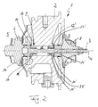
- a charging device 1 which may be formed in particular as an exhaust gas turbocharger for a motor vehicle, not shown, a housing 2 with a shaft 3 rotatably mounted therein.
- the shaft 3 is rotatably supported about a rotation axis 4 and has a turbine wheel 6 on a turbine side 5 and a compressor wheel 8 on a compressor side 7.
- the turbine wheel 6 can be driven by an exhaust gas flow of an equipped with the charging device 1 internal combustion engine, wherein the rotational movement transmitted via the shaft 3 to the compressor 8 and thus the combustion of the combustion engine supplied air is compressed.
- the shaft 3 is in accordance with Fig. 1 and 2 via a bearing device 9 according to the invention mounted on the housing 2, wherein the bearing device 9 comprises two, each end face a radial flange 10, 10 'having bearing bushes 11, 11'.
- the two bushings 11, 11 ' are arranged to each other so that their flanges 10, 10' facing away from each other.
- the two bearing bushes 11, 11' are supported on an associated housing-side contact surface 12, 12 ', whereby a minimum distance of the two bearing bushes 11, 11' from each other is predetermined.
- Both bearing bushes 11, 11 ' are designed as hydrodynamic sliding bearings in which a bearing fluid flow, for example oil, cooling fluid or water, at least between the respective bearing bush 11, 11 'and the shaft to be supported 3 can flow.
- a bearing fluid flow for example oil, cooling fluid or water
- Such a hydrodynamic sliding bearing causes the shaft 3 is mounted without direct contact with the bearing bush 11, 11 '. It slides on a formed between the bushings 11, 11 'and the shaft 3 film from the bearing fluid flow.
- the storage device 9 enables a significantly simplified assembly or a significantly simplified assembly of the charging device 1, since initially, for example, the turbine 6 together with a bearing element 16 and the already pushed onto the shaft 3 bearing bush 11 can be inserted into the housing. Subsequently, the bearing bush 11 'is pushed onto the shaft 3 from the opposite side and then the bearing element 16' and the compressor wheel 8 are arranged on the compressor wheel side 7. As previously required compression of the bushings 11, 11 'in the housing 2 of the charging device 1 is therefore no longer necessary. At the same time, maintenance work on the bearing device 9 and, in particular, replacement of the bearing bushes 11, 11 'can be accomplished much more easily with the bearing bushes 11, 11' according to the invention, which are only loosely inserted, whereby cost advantages can also be realized.
- a radial gap remains between the respective bearing bush 11, 11 'and the housing 2, so that a bearing fluid flow can also flow between the respective bearing bush 11, 11' and the housing 2 in the case of the two bearing bushes 11, 11 '.
- the anti-rotation 13 may be formed in the manner of at least one bearing bush side radially outwardly projecting contour, which engages in a housing-side recess.
- the contour is formed by an axial rib 14 on an outer circumferential surface 15 of the respective bearing bush 11, 11 ', which engages in a complementarily formed and arranged on the housing side axial groove. It is of course also conceivable that the projecting contour is formed on the housing and the associated recess on the bearing bush.
- Axially adjacent to the respective bearing bush 11, 11 ' is a compressor wheel side and Turbinenrad note each have a bearing element 16, 16' is provided, which is in each case to form the axial gap 17, 17 'to one of the two bushings 11, 11'.
- the bearing element 16 is an integral part of the shaft 3, wherein it is also conceivable that the bearing element 16, as in Fig. 1 shown, is designed as a separate component.
- a bearing fluid space 18 is provided, which is communicatively connected to a Lagerfluidzu113 Gustav 19 and is supplied via this with bearing fluid.
- the existing in the bearing fluid space 18 bearing fluid in particular a grease or oil, can flow in the axial direction both between the housing 2 and the respective bearing bush 11, 11 'and between the respective bearing bush 11, 11' and the shaft 3.
- the bearing fluid passes to the axial gap 17, 17 'and is due to a rotational movement of a wall of the axial gap 17, 17' forming, associated bearing element 16, 16 'transported radially outwardly into a non-pressurized storage fluid collection chamber 20.
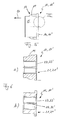
- the transport of the bearing fluid into the bearing fluid collection chamber 20 is additionally supported by the particular embodiment of an end-face axial surface 21, 21 'of the bearing bushes 11, 11'.
- the respective end-side axial surface 21, 21 ' has circular segment-like ramps 22 and 22', wherein each ramp 22, 22 'is oriented in the circumferential direction, that is, rises or falls and by a ramp base 24, 24' designed as a radial groove 23, 23 ' a circular segment-like end face portion 25, 25 'increases.
- each bushing 11, 11' axial inner grooves 26, 26 ' each of which communicating with one of the radial grooves 23, 23' communicates, so that the bearing fluid on the axial inner grooves 26, 26th 'can flow into the associated radial grooves 23, 23'.
- the bearing fluid thus passes through the Lagerfluidzufilmtechnisch 19 in the bearing fluid chamber 18 and thereafter either via a radial gap between the housing 2 and the respective position bushing 11, 11 'or via the axial inner grooves 26, 26' and the axial gap 17, 17 'in the bearing fluid collection chamber 20th
- the axial inner grooves 26, for example, have a rectangular groove bottom, wherein according to the 4 to 6 drawn number of axial inner grooves 26 is to be understood purely by way of example, so that at least one axial inner groove 26 is provided.
- the bearing device 9 is significantly simplified by the bearing device 9 according to the invention, since the bushings 11, 11 'are not pressed into the housing 2 and the rotation must be realized by an additional part to be mounted, but only plugged.
- the anti-rotation 13 is already part of the bearing bush 11, 11 '. Characterized in that the bearing bushes 11, 11 'have a respective flange 10, 10', they are also axially fixed at least in one direction.
- Fig. 7 is the in Fig. 5 circled and denoted by the number VII detail shown.
- the height of the ramps 22 is selected as a function of, for example, the bearing fluid flow to be conveyed, wherein the rise of the ramp 22 is preferably uniform.
- a ramp height h of the ramp 22 is preferably a few hundredths of a millimeter.
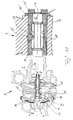
- a bearing device 9 is shown, in which the two bearing bushes 11, 11 'are interconnected.
- the connection can be made for example via a press fit or a clearance fit. It is also conceivable that the two bushings 11, 11 'are glued or screwed together.
- Fig. 10 it can be seen that the two interconnected bearing bushes 11,11 'are secured by a common rotation 13', whereby a "semi-floating" storage is achieved. It is also conceivable omitting the rotation 13 ', so that the two bushings 11, 11' can rotate freely.
- the axial end face 21, 21 ' is usually also provided with ramps or ramps, according to the Fig. 10 but not shown.
- a radial step 28 is arranged to reduce the friction.
- a supply channel 29 to supply the bearing device 9 with lubricant, in particular with oil can be realized, as shown for example in the right detail in Fig. 11 is shown.
- the rotation 13 ' provides the possibility of easy positioning of the bearing device 9 with respect to the housing 2, if, as in Fig. 11 is shown, the anti-rotation 13 'engages not only in the bushings 11, 11', but at the same time in a housing-side recess.
Applications Claiming Priority (1)
| Application Number | Priority Date | Filing Date | Title |
|---|---|---|---|
| DE102007025202A DE102007025202A1 (de) | 2007-05-30 | 2007-05-30 | Lagereinrichtung |
Publications (2)
| Publication Number | Publication Date |
|---|---|
| EP1998009A1 true EP1998009A1 (fr) | 2008-12-03 |
| EP1998009B1 EP1998009B1 (fr) | 2010-10-27 |
Family
ID=39739929
Family Applications (1)
| Application Number | Title | Priority Date | Filing Date |
|---|---|---|---|
| EP08156335A Expired - Fee Related EP1998009B1 (fr) | 2007-05-30 | 2008-05-16 | Dispositif de palier |
Country Status (2)
| Country | Link |
|---|---|
| EP (1) | EP1998009B1 (fr) |
| DE (2) | DE102007025202A1 (fr) |
Cited By (6)
| Publication number | Priority date | Publication date | Assignee | Title |
|---|---|---|---|---|
| US20160010683A1 (en) * | 2014-07-10 | 2016-01-14 | Bosch Mahle Turbo Systems Gmbh & Co. Kg | Axial bearing |
| US20160010684A1 (en) * | 2014-07-10 | 2016-01-14 | Bosch Mahle Turbo Systems Gmbh & Co. Kg | Axial bearing or combined axial/radial bearing |
| EP3444462A4 (fr) * | 2016-05-18 | 2019-06-19 | Mitsubishi Heavy Industries Engine & Turbocharger, Ltd. | Turbocompresseur |
| DE102018204162A1 (de) | 2018-03-19 | 2019-09-19 | Turbo Energy Germany Gmbh | Lagerbuchse für eine Welle eines Turboladers |
| US10443708B2 (en) | 2015-06-23 | 2019-10-15 | United Technologies Corporation | Journal bearing for rotating gear carrier |
| US11460042B2 (en) | 2019-02-27 | 2022-10-04 | Mitsubishi Heavy Industries Engine & Turbocharger, Ltd. | Floating bush bearing device and supercharger |
Families Citing this family (5)
| Publication number | Priority date | Publication date | Assignee | Title |
|---|---|---|---|---|
| DE102007062223A1 (de) * | 2007-12-21 | 2009-06-25 | Bosch Mahle Turbo Systems Gmbh & Co. Kg | Ladeeinrichtung |
| DE102012207660A1 (de) * | 2012-05-08 | 2013-11-14 | Bayerische Motoren Werke Aktiengesellschaft | Wassergeschmierte Wellenanordnung für Turbolader |
| DE102016222625A1 (de) | 2016-11-17 | 2018-05-17 | Turbo Energy Private Limited | Lagerbuchse für eine Welle eines Turboladers |
| DE102017102420A1 (de) * | 2017-02-08 | 2018-08-09 | Abb Turbo Systems Ag | Gleitlagerung mit hydrodynamischer axialsicherung |
| CN113241689B (zh) * | 2021-07-12 | 2021-09-10 | 深圳市顺扬精工电子科技有限公司 | 一种可自动理线的智能型不间断电源的辅助装置 |
Citations (6)
| Publication number | Priority date | Publication date | Assignee | Title |
|---|---|---|---|---|
| DE1221489B (de) | 1959-03-31 | 1966-07-21 | Birmingham Small Arms Co | Lageranordnung fuer die Laeuferwelle eines Turboladers |
| DE1400334A1 (de) * | 1959-08-03 | 1968-10-10 | Schwitzer Corp | Lager,insbesondere fuer hohe Geschwindigkeiten |
| DE8529861U1 (fr) | 1985-10-22 | 1987-06-25 | Mtu Friedrichshafen Gmbh | |
| DE4012361A1 (de) | 1989-04-19 | 1990-10-25 | Aisin Seiki | Oeldichtungsvorrichtung fuer einen turbolader |
| US5509738A (en) | 1994-08-05 | 1996-04-23 | E. I. Du Pont De Nemours And Company | Composite journal and thrust bearing system |
| WO1999007982A1 (fr) | 1997-08-06 | 1999-02-18 | Alliedsignal Inc. | Systeme de palier integre pour turbocompresseur |
Family Cites Families (11)
| Publication number | Priority date | Publication date | Assignee | Title |
|---|---|---|---|---|
| FR765400A (fr) * | 1933-09-07 | 1934-06-08 | Dispositif de graissage automatique des paliers d'excentriques pour concasseurs | |
| BE451922A (fr) * | 1943-08-18 | |||
| US3043636A (en) | 1960-06-29 | 1962-07-10 | Thompson Ramo Wooldridge Inc | Bearing for high speed rotating shafts |
| US3110528A (en) * | 1961-05-16 | 1963-11-12 | Cav Ltd | Shaft bearings |
| US3999874A (en) * | 1975-06-30 | 1976-12-28 | P. R. Mallory & Co. Inc. | Control shaft for a variable resistance control |
| US4134175A (en) * | 1977-09-01 | 1979-01-16 | Liquid Controls Corporation | Non-rotating bushing |
| JPS5945850B2 (ja) * | 1979-07-13 | 1984-11-09 | 株式会社日立製作所 | スラスト軸受 |
| DE3537449A1 (de) * | 1985-10-22 | 1987-01-02 | Mtu Friedrichshafen Gmbh | Lagerung mit schwimmenden buechsen |
| US4704075A (en) | 1986-01-24 | 1987-11-03 | Johnston Andrew E | Turbocharger water-cooled bearing housing |
| DE8811272U1 (fr) * | 1988-09-07 | 1988-10-27 | Holzapfel, Rolf-Dieter, 7321 Albershausen, De | |
| JPH1113476A (ja) * | 1997-06-26 | 1999-01-19 | Ishikawajima Harima Heavy Ind Co Ltd | 過給機用スラスト軸受 |
-
2007
- 2007-05-30 DE DE102007025202A patent/DE102007025202A1/de not_active Withdrawn
-
2008
- 2008-05-16 DE DE502008001622T patent/DE502008001622D1/de active Active
- 2008-05-16 EP EP08156335A patent/EP1998009B1/fr not_active Expired - Fee Related
Patent Citations (6)
| Publication number | Priority date | Publication date | Assignee | Title |
|---|---|---|---|---|
| DE1221489B (de) | 1959-03-31 | 1966-07-21 | Birmingham Small Arms Co | Lageranordnung fuer die Laeuferwelle eines Turboladers |
| DE1400334A1 (de) * | 1959-08-03 | 1968-10-10 | Schwitzer Corp | Lager,insbesondere fuer hohe Geschwindigkeiten |
| DE8529861U1 (fr) | 1985-10-22 | 1987-06-25 | Mtu Friedrichshafen Gmbh | |
| DE4012361A1 (de) | 1989-04-19 | 1990-10-25 | Aisin Seiki | Oeldichtungsvorrichtung fuer einen turbolader |
| US5509738A (en) | 1994-08-05 | 1996-04-23 | E. I. Du Pont De Nemours And Company | Composite journal and thrust bearing system |
| WO1999007982A1 (fr) | 1997-08-06 | 1999-02-18 | Alliedsignal Inc. | Systeme de palier integre pour turbocompresseur |
Cited By (11)
| Publication number | Priority date | Publication date | Assignee | Title |
|---|---|---|---|---|
| US20160010683A1 (en) * | 2014-07-10 | 2016-01-14 | Bosch Mahle Turbo Systems Gmbh & Co. Kg | Axial bearing |
| US20160010684A1 (en) * | 2014-07-10 | 2016-01-14 | Bosch Mahle Turbo Systems Gmbh & Co. Kg | Axial bearing or combined axial/radial bearing |
| US9719558B2 (en) * | 2014-07-10 | 2017-08-01 | Bosch Mahle Turbo Systems Gmbh & Co. Kg | Axial bearing or combined axial/radial bearing |
| US9719557B2 (en) * | 2014-07-10 | 2017-08-01 | Bosch Mahle Turbo Systems Gmbh & Co. Kg | Axial bearing |
| US10443708B2 (en) | 2015-06-23 | 2019-10-15 | United Technologies Corporation | Journal bearing for rotating gear carrier |
| EP3109452B1 (fr) * | 2015-06-23 | 2020-08-19 | United Technologies Corporation | Palier lisse pour support d'engrenage rotatif |
| EP3444462A4 (fr) * | 2016-05-18 | 2019-06-19 | Mitsubishi Heavy Industries Engine & Turbocharger, Ltd. | Turbocompresseur |
| US10895226B2 (en) | 2016-05-18 | 2021-01-19 | Mitsubishi Heavy Industries Engine & Turbocharger, Ltd. | Turbocharger |
| DE102018204162A1 (de) | 2018-03-19 | 2019-09-19 | Turbo Energy Germany Gmbh | Lagerbuchse für eine Welle eines Turboladers |
| WO2019179771A1 (fr) | 2018-03-19 | 2019-09-26 | Turbo Energy Germany Gmbh | Coussinet pour un arbre d'un turbocompresseur |
| US11460042B2 (en) | 2019-02-27 | 2022-10-04 | Mitsubishi Heavy Industries Engine & Turbocharger, Ltd. | Floating bush bearing device and supercharger |
Also Published As
| Publication number | Publication date |
|---|---|
| DE502008001622D1 (de) | 2010-12-09 |
| DE102007025202A1 (de) | 2008-12-04 |
| EP1998009B1 (fr) | 2010-10-27 |
Similar Documents
| Publication | Publication Date | Title |
|---|---|---|
| EP1998009B1 (fr) | Dispositif de palier | |
| EP1995417B1 (fr) | Arbre à came | |
| DE3628687C2 (fr) | ||
| DE102008058618B4 (de) | Baukastensystem für Abgasturbolader | |
| WO2012139830A1 (fr) | Ensemble palier pour un turbocompresseur | |
| WO2012079881A1 (fr) | Ensemble palier pour un turbocompresseur et turbocompresseur | |
| DE102010054905A1 (de) | Lagereinheit für einen Turbolader | |
| EP3208464B1 (fr) | Pompe centrifuge | |
| DE102009005386A1 (de) | Ladeeinrichtung für eine Brennkraftmaschine | |
| DE102007019338A1 (de) | Axiallager insbesondere für einen Turbolader | |
| DE102018104685A1 (de) | Antriebsvorrichtung mit einem Elektromotor und einem Getriebe | |
| DE102010054904A1 (de) | Lagerkartusche für einen Turbolader | |
| WO2012079788A1 (fr) | Unité de palier pour turbocompresseur | |
| DE102008059598A1 (de) | Abgasturbolader | |
| WO2012079882A1 (fr) | Unité de palier pour un turbocompresseur | |
| DE102010007668A1 (de) | Getriebeelement für ein Spannungswellengetriebe, Nockenwellenversteller sowie Lenkkrafthilfe | |
| WO2020083434A1 (fr) | Dispositif palier pour un turbocompresseur à gaz d'échappement et turbocompresseur à gaz d'échappement | |
| DE102016005644A1 (de) | Lagereinrichtung zum axialen Lagern einer Kurbelwelle einer Hubkolbenmaschine | |
| DE102017120578A1 (de) | Kippsegmentlager, insbesondere Radialkippsegmentlager | |
| DE102009053101B4 (de) | Turbolader mit einem Turboladergehäuse und einer Aufnahmeeinrichtung für das Laufzeug des Turboladers | |
| DE10238415B4 (de) | Gleitlager für eine Welle eines Abgasturboladers | |
| DE102013113710A1 (de) | Lagervorrichtung für einen Abgasturbolader und Abgasturbolader | |
| DE102012018330A1 (de) | Kurbelwelle zur Anordnung in einem Kurbelgehäuse eines Verbrennungsmotors und Verfahren zur Herstellung | |
| EP1952035B1 (fr) | Vilebrequin assemble | |
| DE102008045229B4 (de) | Axiallager |
Legal Events
| Date | Code | Title | Description |
|---|---|---|---|
| PUAI | Public reference made under article 153(3) epc to a published international application that has entered the european phase |
Free format text: ORIGINAL CODE: 0009012 |
|
| AK | Designated contracting states |
Kind code of ref document: A1 Designated state(s): AT BE BG CH CY CZ DE DK EE ES FI FR GB GR HR HU IE IS IT LI LT LU LV MC MT NL NO PL PT RO SE SI SK TR |
|
| AX | Request for extension of the european patent |
Extension state: AL BA MK RS |
|
| RIN1 | Information on inventor provided before grant (corrected) |
Inventor name: WEISZ, RAFAEL Inventor name: AHRENS, THOMAS |
|
| 17P | Request for examination filed |
Effective date: 20090217 |
|
| 17Q | First examination report despatched |
Effective date: 20090428 |
|
| AKX | Designation fees paid |
Designated state(s): DE FR GB |
|
| GRAP | Despatch of communication of intention to grant a patent |
Free format text: ORIGINAL CODE: EPIDOSNIGR1 |
|
| RTI1 | Title (correction) |
Free format text: BEARING DEVICE |
|
| GRAS | Grant fee paid |
Free format text: ORIGINAL CODE: EPIDOSNIGR3 |
|
| GRAA | (expected) grant |
Free format text: ORIGINAL CODE: 0009210 |
|
| AK | Designated contracting states |
Kind code of ref document: B1 Designated state(s): DE FR GB |
|
| REG | Reference to a national code |
Ref country code: GB Ref legal event code: FG4D Free format text: NOT ENGLISH |
|
| REF | Corresponds to: |
Ref document number: 502008001622 Country of ref document: DE Date of ref document: 20101209 Kind code of ref document: P |
|
| PLBE | No opposition filed within time limit |
Free format text: ORIGINAL CODE: 0009261 |
|
| STAA | Information on the status of an ep patent application or granted ep patent |
Free format text: STATUS: NO OPPOSITION FILED WITHIN TIME LIMIT |
|
| 26N | No opposition filed |
Effective date: 20110728 |
|
| REG | Reference to a national code |
Ref country code: DE Ref legal event code: R097 Ref document number: 502008001622 Country of ref document: DE Effective date: 20110728 |
|
| REG | Reference to a national code |
Ref country code: FR Ref legal event code: PLFP Year of fee payment: 9 |
|
| REG | Reference to a national code |
Ref country code: FR Ref legal event code: PLFP Year of fee payment: 10 |
|
| REG | Reference to a national code |
Ref country code: FR Ref legal event code: PLFP Year of fee payment: 11 |
|
| REG | Reference to a national code |
Ref country code: DE Ref legal event code: R082 Ref document number: 502008001622 Country of ref document: DE Representative=s name: BRP RENAUD UND PARTNER MBB RECHTSANWAELTE PATE, DE Ref country code: DE Ref legal event code: R081 Ref document number: 502008001622 Country of ref document: DE Owner name: BMTS TECHNOLOGY GMBH & CO. KG, DE Free format text: FORMER OWNER: BOSCH MAHLE TURBO SYSTEMS GMBH & CO. KG, 70376 STUTTGART, DE |
|
| PGFP | Annual fee paid to national office [announced via postgrant information from national office to epo] |
Ref country code: FR Payment date: 20200528 Year of fee payment: 13 |
|
| PGFP | Annual fee paid to national office [announced via postgrant information from national office to epo] |
Ref country code: GB Payment date: 20200528 Year of fee payment: 13 |
|
| PGFP | Annual fee paid to national office [announced via postgrant information from national office to epo] |
Ref country code: DE Payment date: 20200728 Year of fee payment: 13 |
|
| REG | Reference to a national code |
Ref country code: DE Ref legal event code: R119 Ref document number: 502008001622 Country of ref document: DE |
|
| GBPC | Gb: european patent ceased through non-payment of renewal fee |
Effective date: 20210516 |
|
| PG25 | Lapsed in a contracting state [announced via postgrant information from national office to epo] |
Ref country code: GB Free format text: LAPSE BECAUSE OF NON-PAYMENT OF DUE FEES Effective date: 20210516 Ref country code: DE Free format text: LAPSE BECAUSE OF NON-PAYMENT OF DUE FEES Effective date: 20211201 |
|
| PG25 | Lapsed in a contracting state [announced via postgrant information from national office to epo] |
Ref country code: FR Free format text: LAPSE BECAUSE OF NON-PAYMENT OF DUE FEES Effective date: 20210531 |