EP1997774B1 - Method for producing hydrogen by using different metals - Google Patents
Method for producing hydrogen by using different metals Download PDFInfo
- Publication number
- EP1997774B1 EP1997774B1 EP08150906.9A EP08150906A EP1997774B1 EP 1997774 B1 EP1997774 B1 EP 1997774B1 EP 08150906 A EP08150906 A EP 08150906A EP 1997774 B1 EP1997774 B1 EP 1997774B1
- Authority
- EP
- European Patent Office
- Prior art keywords
- metal
- cathode
- hydrogen
- anode
- stainless steel
- Prior art date
- Legal status (The legal status is an assumption and is not a legal conclusion. Google has not performed a legal analysis and makes no representation as to the accuracy of the status listed.)
- Not-in-force
Links
Images





Classifications
-
- C—CHEMISTRY; METALLURGY
- C01—INORGANIC CHEMISTRY
- C01B—NON-METALLIC ELEMENTS; COMPOUNDS THEREOF; METALLOIDS OR COMPOUNDS THEREOF NOT COVERED BY SUBCLASS C01C
- C01B3/00—Hydrogen; Gaseous mixtures containing hydrogen; Separation of hydrogen from mixtures containing it; Purification of hydrogen; Reversible storage of hydrogen
- C01B3/02—Production of hydrogen; Production of gaseous mixtures containing hydrogen
- C01B3/06—Production of hydrogen; Production of gaseous mixtures containing hydrogen by reaction of inorganic compounds containing electro-positively bound hydrogen with inorganic reducing agents
- C01B3/08—Production of hydrogen; Production of gaseous mixtures containing hydrogen by reaction of inorganic compounds containing electro-positively bound hydrogen with inorganic reducing agents by reaction of inorganic compounds with metals
-
- C—CHEMISTRY; METALLURGY
- C25—ELECTROLYTIC OR ELECTROPHORETIC PROCESSES; APPARATUS THEREFOR
- C25B—ELECTROLYTIC OR ELECTROPHORETIC PROCESSES FOR THE PRODUCTION OF COMPOUNDS OR NON-METALS; APPARATUS THEREFOR
- C25B11/00—Electrodes; Manufacture thereof not otherwise provided for
- C25B11/02—Electrodes; Manufacture thereof not otherwise provided for characterised by shape or form
- C25B11/03—Electrodes; Manufacture thereof not otherwise provided for characterised by shape or form perforated or foraminous
-
- C—CHEMISTRY; METALLURGY
- C25—ELECTROLYTIC OR ELECTROPHORETIC PROCESSES; APPARATUS THEREFOR
- C25B—ELECTROLYTIC OR ELECTROPHORETIC PROCESSES FOR THE PRODUCTION OF COMPOUNDS OR NON-METALS; APPARATUS THEREFOR
- C25B5/00—Electrogenerative processes, i.e. processes for producing compounds in which electricity is generated simultaneously
-
- Y—GENERAL TAGGING OF NEW TECHNOLOGICAL DEVELOPMENTS; GENERAL TAGGING OF CROSS-SECTIONAL TECHNOLOGIES SPANNING OVER SEVERAL SECTIONS OF THE IPC; TECHNICAL SUBJECTS COVERED BY FORMER USPC CROSS-REFERENCE ART COLLECTIONS [XRACs] AND DIGESTS
- Y02—TECHNOLOGIES OR APPLICATIONS FOR MITIGATION OR ADAPTATION AGAINST CLIMATE CHANGE
- Y02E—REDUCTION OF GREENHOUSE GAS [GHG] EMISSIONS, RELATED TO ENERGY GENERATION, TRANSMISSION OR DISTRIBUTION
- Y02E60/00—Enabling technologies; Technologies with a potential or indirect contribution to GHG emissions mitigation
- Y02E60/30—Hydrogen technology
- Y02E60/36—Hydrogen production from non-carbon containing sources, e.g. by water electrolysis
Definitions
- the present invention relates to a method for producing hydrogen, and particularly to a method for producing hydrogen by using magnesium alloy scrap and stainless steel through spontaneous chemical reaction and a reaction of electrochemistry caused without extra energy consumption.
- Hydrogen is a non-pollution resource, which can be adapted to fuel, Ni-MH battery, and energy for industrials, such as desulfuration materials for oil working, chemical industrial, metallurgy industrial, and semi-conductor industry. Besides, hydrogen reacted in fuel cells do not produce carbon dioxide, therefore, hydrogen is expected to be new resource of energy in the development of the fuel cells. It is no doubt that increasing research on hydrogen is inevitable in the near future. Thus the study of application of hydrogen is very important.
- an object of the present invention is to provide an innovative method for producing hydrogen from reduction potential difference generated between two different metals through spontaneous chemical reaction without consuming extra energy and causing environmental pollution.
- the method of the present invention is to provide a metal of lower reduction potential as an anode metal, said anode metal comprising magnesium alloy scrap, and a metal of higher reduction potential as a cathode metal, said cathode metal comprising stainless steel and said cathode metal being shaped as a plate, mesh, gill net or powder, combining said anode metal and said cathode metal by smashing and extruding the anode metal, and then rolling the cathode metal to be tightly attached to the smashed anode metal, and immersing said combined metals in an electrolyte, whereby hydrogen and side-products are generated from a reaction of electrochemistry caused by reduction potential difference between the different metals.
- magnesium alloy is used as the anode metal
- stainless steel is used as the cathode metal
- the electrolyte can be sodium chloride solution, normal saline, or KCl solution.
- Photographs 1 to 5 show development of the different metals being smashed, extruded and immersed in an electrolyte after electrochemistry reaction.
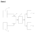
- Illustrated in Fig. 1 is a flowchart of a method for producing hydrogen by using different metals of the present invention.
- the method includes: providing a metal of lower reduction potential as an anode metal 10 and a metal of higher reduction potential as a cathode metal 20, and combine the anode metal 10 and the cathode metal 20 by appropriate steps 60 (described below) and then immerse the combined metals 10, 20 in an electrolyte, whereby hydrogen 40 and side-products 50 generated from a reaction 30 of electrochemistry caused by reduction potential difference between the different metals 10, 20, wherein the anode metal 10 can be magnesium alloy scrap, and the cathode metal 20 can be stainless steel.
- the anode metal 10 is magnesium alloy scrap
- the cathode metal 20 is stainless steel AISI 304.
- the anode metal 10 and the cathode metal 20 are combined with combining steps 60, which can be generally classified as to smash and extrude the anode metal 10 to a certain form and then the cathode metal 20 is rolled to attach on the anode metal 10, the cathode metal 20 shaped as a mesh, gill net, or powder (in the preferred embodiment, the cathode is mesh-like as shown in photographs 1 to 3).
- the combining steps 60 are described as follows: first, smash a case of magnesium alloy scrap and extrude to a certain form, then roll a stainless steel mesh (AISI 304) to be tightly attached on the magnesium alloy scrap by stamping techniques, whereby the combining steps 60 is completed. Further referring to photographs 4 and 5, the combined two metals 10, 20 are immersed in normal saline, which is functioned as an electrolyte, and therefore cause a reaction of electrochemistry 30. Particularly, in this embodiment, an optimum value of a mutual potential difference between the anode and the cathode metals 10, 20 is within 0.71 V to 3.49V
- calomel electrode Hg 2 Cl 2
- the mutual potential difference between the anode and cathode metals is within 0.88V to 2.01V
- the anode and cathode metals immersed in normal saline causes the reaction of electrochemistry 30, wherein the normal saline is used as the electrolyte, which can be replaced by sodium chloride solution, or KCl solution, because potassium and chlorine ions thereof do not affect H + and OH- in water.
- electrochemistry 30 wherein the normal saline is used as the electrolyte, which can be replaced by sodium chloride solution, or KCl solution, because potassium and chlorine ions thereof do not affect H + and OH- in water.
- hydrogen 40 and side-products 50 such as hydroxide are generated from the reaction of electrochemistry 30, for which a reaction formula is as follows: Mg + 2 H 2 O ⁇ Mg(OH) 2 + H 2
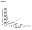
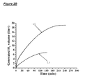
- Figs. 2A and 2B are relation diagrams respectively illustrating relation between hydrogen generation rate and time, and relation between generated hydrogen volume and time. It is clearly from Figs. 2A and 2B that under same conditions (with 1500ml, 3.5 wt.% sodium chloride solution, magnesium alloy designated as an anode, stainless steel mesh (AISI 304) with size of 2 x 8 cm2 designated as a cathode), more pieces of the stainless steel mesh bring higher hydrogen generation rate and generated hydrogen volume. As shown in Figs. 2A and 2B , a reaction curve L5 representing one piece of the stainless steel mesh has lower performance than a reaction curve L6 representing four pieces of the stainless steel mesh.
- the anode metal 10 and the cathode metal 20 can be combined by melting the magnesium alloy scrap 10 (anode metal) to liquid status, then immerse one surface of the stainless steel mesh 20 (AISI 304, cathode metal) in the melting liquid metal 10 in order to shorten a path of electron transport between the anode and cathode metals during the reaction of electrochemistry and to increase hydrogen production, as shown in Fig. 3A , the stainless steel mesh 20 being immersed with one surface only.
- the stainless steel mesh 20 is immersed with only middle parts thereof in the liquid 10, two ends of the stainless steel mesh which are exposed out of the liquid 10. Still further, the stainless steel mesh 20 can be folded to multiple parts before immersing (as shown in Fig. 5A ), and then immerse middle parts of the folded stainless steel mesh 20 through which to increase contact area with the melting liquid 10. In addition to one surface immersed, two surfaces of the stainless steel mesh 20 (cathode metal) can be immersed as well. Further referring to Figs. 3B to Figs. 7B , in comparison with conventional methods of immersion (as shown in Fig.
- the magnesium alloy scrap 10 remains lots of area not being reacted after the reaction of electrochemistry 30, however, in contrast, in the preferred embodiment of the present invention, there is only few parts of the magnesium alloy scrap 10 not being reacted, that is, the present invention has better efficiency of hydrogen generation than conventions.
- Example conditions are the same in the comparative experiments, i.e. 1500ml, 3.5 wt.% sodium chloride solution, 10 pieces of stainless steel mesh (AISI 304) with size of 2 x 8 cm2 designated as a cathode).
- a relation diagram illustrating relation between generated H 2 volume and time in which a reaction curve L1 (representing one surface immersed), L2 (multiple folds immersed), L3 (two surfaces immersed), and L4 (conventions) respectively shows different development in different conditions. It is clearly that after sixty minutes immersion, a reaction rate of the curve L4 becomes slow, while the curves L1, L2, L3 keep rising which prove that the present invention improve efficiency of hydrogen production.
- the step of the union of two metals besides using the above described methods of smashing and extrusion with rolling together or immersion in a liquid melt, also may be carried out by directly combining the two metals in the electrolyte with a continuous rolling action, which similarly may achieve the combination of the two metals so that the reduction potential difference between them causes an electrochemical reaction to yield the hydrogen gas and the side-products.
- Figs. 6A and 6B are schematic views of a third embodiment (this embodiment does not fall within the scope of the present invention).
- the combining steps 60 is to utilize the electrolyte as an intermedium to make the smashed anode metal 10' and the mesh-like cathode metal 20' contact with each other and further cause a reaction of the of electrochemistry.
- the electrolyte drives the smashed anode metal 10' to contact the mesh-like cathode metal 20', or the mesh-like cathode metal 20' can be moved to contact the smashed anode metal 10' in the electrolyte.
- the method of the present invention not only produces hydrogen by using magnesium alloy scrap but also produces side-product magnesium hydroxide and prevents environmental pollution.
Landscapes
- Chemical & Material Sciences (AREA)
- Organic Chemistry (AREA)
- Chemical Kinetics & Catalysis (AREA)
- Engineering & Computer Science (AREA)
- Metallurgy (AREA)
- Materials Engineering (AREA)
- Electrochemistry (AREA)
- General Health & Medical Sciences (AREA)
- Inorganic Chemistry (AREA)
- Combustion & Propulsion (AREA)
- Health & Medical Sciences (AREA)
- Manufacture And Refinement Of Metals (AREA)
- Electrolytic Production Of Non-Metals, Compounds, Apparatuses Therefor (AREA)
- Electrolytic Production Of Metals (AREA)
Description
- The present invention relates to a method for producing hydrogen, and particularly to a method for producing hydrogen by using magnesium alloy scrap and stainless steel through spontaneous chemical reaction and a reaction of electrochemistry caused without extra energy consumption.
- Hydrogen is a non-pollution resource, which can be adapted to fuel, Ni-MH battery, and energy for industrials, such as desulfuration materials for oil working, chemical industrial, metallurgy industrial, and semi-conductor industry. Besides, hydrogen reacted in fuel cells do not produce carbon dioxide, therefore, hydrogen is expected to be new resource of energy in the development of the fuel cells. It is no doubt that increasing research on hydrogen is inevitable in the near future. Thus the study of application of hydrogen is very important.
- As is well known, there are many ways to produce hydrogen, such as steam reforming, partial oxidation, gasification, and producing by electrolyte solution; however, hydrogen produced by the preceding three ways will generate carbon dioxide as well, which is unnecessary and not benefit to our earth, especially that carbon dioxide is the main factor causing global warming. Unfortunately, the fourth way mentioned before requires a large electricity consumption during processes of hydrogen production, and which results in higher cost, not economic benefits.
- Although aforementioned ways are not the ideal ways to produce hydrogen, there is one method of producing hydrogen that is by using metal scrap. For instance, recycle disused aluminum cans as material of hydrogen production, but it still has to wash away coating of the cans by chemical solution, which may result in wastewater pollution.
US 4072514 describes a hydrogen production process in which a magnesium composite, formed by causing finely divided metals consisting of iron, zinc, chromium, aluminium and manganese to be attached to the surface of magnesium, is immersed in an aqueous material such as sea water. - Accordingly, an object of the present invention is to provide an innovative method for producing hydrogen from reduction potential difference generated between two different metals through spontaneous chemical reaction without consuming extra energy and causing environmental pollution.
- To achieve the above-mentioned objects, the method of the present invention is to provide a metal of lower reduction potential as an anode metal, said anode metal comprising magnesium alloy scrap, and a metal of higher reduction potential as a cathode metal, said cathode metal comprising stainless steel and said cathode metal being shaped as a plate, mesh, gill net or powder,
combining said anode metal and said cathode metal by smashing and extruding the anode metal, and then rolling the cathode metal to be tightly attached to the smashed anode metal, and
immersing said combined metals in an electrolyte,
whereby hydrogen and side-products are generated from a reaction of electrochemistry caused by reduction potential difference between the different metals. - According to the above-mentioned features, magnesium alloy is used as the anode metal, and stainless steel is used as the cathode metal.
- Moreover, the electrolyte can be sodium chloride solution, normal saline, or KCl solution.
- To combine the two different metals in such way can simplify processes and economize energy.
-
-
Fig. 1 is a flowchart depicting a method for producing hydrogen by using different metals of the present invention; -
Figs. 2A and2B are relation diagrams respectively illustrating relation between hydrogen generation rate and time, and relation between generated hydrogen volume and time; -
Fig. 2C is a relation diagram illustrating relation between generated hydrogen volume and time with different methods of immersion; -
Figs. 3A and 3B to Figs. 5A and 5B are schematic views of a second embodiment, which illustrate development of the different metals being immersed before and after (the second embodiment does not fall within the scope of the present invention); -
Figs. 6A and 6B are schematic views of a third embodiment of the present invention (the third embodiment does not fall within the scope of the present invention); -
Figs. 7A and 7B are conventional arts showing different metals combined and immersed; and -
Photographs 1 to 5 show development of the different metals being smashed, extruded and immersed in an electrolyte after electrochemistry reaction. - Illustrated in
Fig. 1 is a flowchart of a method for producing hydrogen by using different metals of the present invention. The method includes: providing a metal of lower reduction potential as ananode metal 10 and a metal of higher reduction potential as acathode metal 20, and combine theanode metal 10 and thecathode metal 20 by appropriate steps 60 (described below) and then immerse the combinedmetals hydrogen 40 and side-products 50 generated from areaction 30 of electrochemistry caused by reduction potential difference between thedifferent metals anode metal 10 can be magnesium alloy scrap, and thecathode metal 20 can be stainless steel. In this preferred embodiment, theanode metal 10 is magnesium alloy scrap, and thecathode metal 20 is stainless steel AISI 304. - The
anode metal 10 and thecathode metal 20 are combined with combiningsteps 60, which can be generally classified as to smash and extrude theanode metal 10 to a certain form and then thecathode metal 20 is rolled to attach on theanode metal 10, thecathode metal 20 shaped as a mesh, gill net, or powder (in the preferred embodiment, the cathode is mesh-like as shown inphotographs 1 to 3). - Referring to
photographs 1 to 3, the combiningsteps 60 are described as follows: first, smash a case of magnesium alloy scrap and extrude to a certain form, then roll a stainless steel mesh (AISI 304) to be tightly attached on the magnesium alloy scrap by stamping techniques, whereby the combiningsteps 60 is completed. Further referring tophotographs metals electrochemistry 30. Particularly, in this embodiment, an optimum value of a mutual potential difference between the anode and thecathode metals - If a calomel electrode (Hg2Cl2) is used to be the standard potential, the mutual potential difference between the anode and cathode metals is within 0.88V to 2.01V
- Moreover, the anode and cathode metals immersed in normal saline causes the reaction of
electrochemistry 30, wherein the normal saline is used as the electrolyte, which can be replaced by sodium chloride solution, or KCl solution, because potassium and chlorine ions thereof do not affect H+ and OH- in water. Accordingly,hydrogen 40 and side-products 50 such as hydroxide are generated from the reaction ofelectrochemistry 30, for which a reaction formula is as follows:
Mg + 2 H2O→Mg(OH)2 + H2
- It may be known from the above reaction formula that following the reaction, as well as obtaining the hydrogen gas to utilize, there may also be obtained the side-product of magnesium hydroxide, a heat-resisting product being a flame-resistant raw material.
-
Figs. 2A and2B are relation diagrams respectively illustrating relation between hydrogen generation rate and time, and relation between generated hydrogen volume and time. It is clearly fromFigs. 2A and2B that under same conditions (with 1500ml, 3.5 wt.% sodium chloride solution, magnesium alloy designated as an anode, stainless steel mesh (AISI 304) with size of 2 x 8 cm2 designated as a cathode), more pieces of the stainless steel mesh bring higher hydrogen generation rate and generated hydrogen volume. As shown inFigs. 2A and2B , a reaction curve L5 representing one piece of the stainless steel mesh has lower performance than a reaction curve L6 representing four pieces of the stainless steel mesh. - With reference to
Figs. 3A and 3B to Figs. 5A and 5B for the second type of the combining steps 60 (this method of combining does not fall within the scope of the present invention), theanode metal 10 and thecathode metal 20 can be combined by melting the magnesium alloy scrap 10 (anode metal) to liquid status, then immerse one surface of the stainless steel mesh 20 (AISI 304, cathode metal) in the meltingliquid metal 10 in order to shorten a path of electron transport between the anode and cathode metals during the reaction of electrochemistry and to increase hydrogen production, as shown inFig. 3A , thestainless steel mesh 20 being immersed with one surface only. Furthermore, thestainless steel mesh 20 is immersed with only middle parts thereof in theliquid 10, two ends of the stainless steel mesh which are exposed out of theliquid 10. Still further, thestainless steel mesh 20 can be folded to multiple parts before immersing (as shown inFig. 5A ), and then immerse middle parts of the foldedstainless steel mesh 20 through which to increase contact area with the meltingliquid 10. In addition to one surface immersed, two surfaces of the stainless steel mesh 20 (cathode metal) can be immersed as well. Further referring toFigs. 3B to Figs. 7B , in comparison with conventional methods of immersion (as shown inFig. 6A ), themagnesium alloy scrap 10 remains lots of area not being reacted after the reaction ofelectrochemistry 30, however, in contrast, in the preferred embodiment of the present invention, there is only few parts of themagnesium alloy scrap 10 not being reacted, that is, the present invention has better efficiency of hydrogen generation than conventions. (Experimental conditions are the same in the comparative experiments, i.e. 1500ml, 3.5 wt.% sodium chloride solution, 10 pieces of stainless steel mesh (AISI 304) with size of 2 x 8 cm2 designated as a cathode). - Further referring to
Fig. 2C in combination withFigs. 7A and 7B , a relation diagram illustrating relation between generated H2 volume and time, in which a reaction curve L1 (representing one surface immersed), L2 (multiple folds immersed), L3 (two surfaces immersed), and L4 (conventions) respectively shows different development in different conditions. It is clearly that after sixty minutes immersion, a reaction rate of the curve L4 becomes slow, while the curves L1, L2, L3 keep rising which prove that the present invention improve efficiency of hydrogen production. - The step of the union of two metals, besides using the above described methods of smashing and extrusion with rolling together or immersion in a liquid melt, also may be carried out by directly combining the two metals in the electrolyte with a continuous rolling action, which similarly may achieve the combination of the two metals so that the reduction potential difference between them causes an electrochemical reaction to yield the hydrogen gas and the side-products.
- With reference to
Figs. 6A and 6B, Figs. 6A and 6B are schematic views of a third embodiment (this embodiment does not fall within the scope of the present invention). In the third embodiment, the combining steps 60 is to utilize the electrolyte as an intermedium to make the smashed anode metal 10' and the mesh-like cathode metal 20' contact with each other and further cause a reaction of the of electrochemistry. As shown inFigs. 6A and 6B , the electrolyte drives the smashed anode metal 10' to contact the mesh-like cathode metal 20', or the mesh-like cathode metal 20' can be moved to contact the smashed anode metal 10' in the electrolyte. - Accordingly, the method of the present invention not only produces hydrogen by using magnesium alloy scrap but also produces side-product magnesium hydroxide and prevents environmental pollution.
Claims (3)
- A method for producing hydrogen by using different metals, comprising:providing a metal of lower reduction potential as an anode metal, said anode metal comprising magnesium alloy scrap, and a metal of higher reduction potential as a cathode metal, said cathode metal comprising stainless steel and said cathode metal being shaped as a plate, mesh, gill net, or powder;
combining said anode metal and said cathode metal by smashing and extruding the anode metal, and then rolling the cathode metal to be tightly attached to the smashed anode metal, and
immersing said combined metals in an electrolyte,
whereby hydrogen and side-products are generated from a reaction of electrochemistry caused by reduction potential difference between the different metals. - The method as claimed in Claim 1, wherein the cathode metal comprises stainless steel mesh.
- The method as claimed in Claim 1 or Claim 2, wherein the electrolyte is sodium chloride solution, normal saline, or KCl solution, because potassium and chlorine ions thereof do not affect H+ and OH- in water.
Applications Claiming Priority (2)
| Application Number | Priority Date | Filing Date | Title |
|---|---|---|---|
| TW096118619A TW200846499A (en) | 2007-05-24 | 2007-05-24 | Method of generating hydrogen using dissimilar metal |
| US12/003,688 US7704484B2 (en) | 2007-05-24 | 2007-12-31 | Method for producing hydrogen by using different metals |
Publications (2)
| Publication Number | Publication Date |
|---|---|
| EP1997774A1 EP1997774A1 (en) | 2008-12-03 |
| EP1997774B1 true EP1997774B1 (en) | 2015-06-24 |
Family
ID=39712287
Family Applications (1)
| Application Number | Title | Priority Date | Filing Date |
|---|---|---|---|
| EP08150906.9A Not-in-force EP1997774B1 (en) | 2007-05-24 | 2008-01-31 | Method for producing hydrogen by using different metals |
Country Status (1)
| Country | Link |
|---|---|
| EP (1) | EP1997774B1 (en) |
Family Cites Families (9)
| Publication number | Priority date | Publication date | Assignee | Title |
|---|---|---|---|---|
| GB190903188A (en) * | 1909-02-09 | 1909-09-30 | George William Johnson | Improvements in Means for the Preparation of Pure Hydrogen. |
| US2623812A (en) * | 1943-07-08 | 1952-12-30 | Liddiard | Production of hydrogen |
| US3256504A (en) * | 1961-01-11 | 1966-06-14 | Fidelman Morris | Galvanic hydrogen producer |
| US4072514A (en) * | 1971-04-20 | 1978-02-07 | Suzuki Masahiro | Magnesium composites and mixtures for hydrogen generation and method for manufacture thereof |
| US4264362A (en) * | 1977-11-25 | 1981-04-28 | The United States Of America As Represented By The Secretary Of The Navy | Supercorroding galvanic cell alloys for generation of heat and gas |
| US5089107A (en) * | 1990-07-18 | 1992-02-18 | Francisco Pacheco | Bi-polar auto electrolytic hydrogen generator |
| US5514353A (en) * | 1994-06-28 | 1996-05-07 | Af Sammer Corporation | Demand responsive hydrogen generator based on hydride water reaction |
| US6800258B2 (en) * | 2000-07-20 | 2004-10-05 | Erling Reidar Andersen | Apparatus for producing hydrogen |
| WO2002014214A1 (en) * | 2000-08-18 | 2002-02-21 | Valery Armenakovich Grigoryan | Method for producing hydrogen and heat energy |
-
2008
- 2008-01-31 EP EP08150906.9A patent/EP1997774B1/en not_active Not-in-force
Also Published As
| Publication number | Publication date |
|---|---|
| EP1997774A1 (en) | 2008-12-03 |
Similar Documents
| Publication | Publication Date | Title |
|---|---|---|
| Liu et al. | Innovations in electrocatalysts, hybrid anodic oxidation, and electrolyzers for enhanced direct seawater electrolysis | |
| Ye et al. | Prospects and challenges of green ammonia synthesis | |
| Kjartansdóttir et al. | Development of durable and efficient electrodes for large-scale alkaline water electrolysis | |
| Liu et al. | Shape-dependent electrocatalytic reduction of CO2 to CO on triangular silver nanoplates | |
| Gautam et al. | Heterointerface of vanadium telluride and zinc iron telluride nanosheets for highly efficient hydrogen production via water and urea electrolysis | |
| US7704484B2 (en) | Method for producing hydrogen by using different metals | |
| Xu et al. | Challenges and emerging trends in hydrogen energy industrialization: from hydrogen evolution reaction to storage, transportation, and utilization | |
| Ye et al. | Unraveling the crucial contribution of additive chromate to efficient and stable alkaline seawater oxidation on Ni-based layered double hydroxides | |
| Li et al. | Ultrafast synthesis of an efficient urea oxidation electrocatalyst for urea-assisted fast-charging Zn–air batteries and water splitting | |
| Magray et al. | Modulating energy storage and electrocatalytic properties of molybdates through forming solid solutions | |
| Huang et al. | Anion-mediated in situ reconstruction of the Bi2MoO6 precatalyst for enhanced electrochemical CO2 reduction over a wide potential window | |
| Hassan et al. | Recent progress on electrocatalysts in ammonia electrooxidation reaction for clean hydrogen production | |
| Uzgoren et al. | Development of IrO2–WO3 composite catalysts from waste WC–Co wire drawing die for PEM water electrolyzers’ oxygen evolution reactions | |
| Zulfiqar et al. | Highly selective and corrosion resistant interconnected pNiCo@ NF electrocatalysts for methanol-assisted seawater electrolysis | |
| Tang et al. | Microzone-acidification-driven degradation mechanism of the NiFe-based anode in seawater electrolysis | |
| Telli et al. | Electrocatalytic oxidation of methanol on Ru deposited NiZn catalyst at graphite in alkaline medium | |
| Wei et al. | Multifold nanotwin-enhanced catalytic activity of Ni-Zn-Cu for hydrazine oxidation | |
| He et al. | Heterostructure WC/Ni/Cu nanorod array towards ultra-long hydrogen evolution durability at room temperature and industrial conditions | |
| Wang et al. | Porous Co–P–Pd nanotube arrays for hydrogen generation by catalyzing the hydrolysis of alkaline NaBH 4 solution | |
| EP2202198A1 (en) | Method for producing hydrogen and applications thereof | |
| Martínez et al. | DEMS study of hydrogen evolution reaction at Ni/reduced graphene oxides/Mo2C composites | |
| Tan et al. | Interfacial charge modulation in CuNi alloy core/B, N-doped graphene shell enabling 100% ammonia-to-nitrite selectivity | |
| El Ghetany et al. | Theoretical Study of a Water Electrolyzer System for a Green Hydrogen Production Performance Evaluation Prediction. | |
| EP1997774A1 (en) | Method for producing hydrogen by using different metals | |
| US10906805B2 (en) | Method for storing electrical energy in solid matter |
Legal Events
| Date | Code | Title | Description |
|---|---|---|---|
| PUAI | Public reference made under article 153(3) epc to a published international application that has entered the european phase |
Free format text: ORIGINAL CODE: 0009012 |
|
| AK | Designated contracting states |
Kind code of ref document: A1 Designated state(s): AT BE BG CH CY CZ DE DK EE ES FI FR GB GR HR HU IE IS IT LI LT LU LV MC MT NL NO PL PT RO SE SI SK TR |
|
| AX | Request for extension of the european patent |
Extension state: AL BA MK RS |
|
| 17P | Request for examination filed |
Effective date: 20090422 |
|
| 17Q | First examination report despatched |
Effective date: 20090529 |
|
| AKX | Designation fees paid |
Designated state(s): AT BE BG CH CY CZ DE DK EE ES FI FR GB GR HR HU IE IS IT LI LT LU LV MC MT NL NO PL PT RO SE SI SK TR |
|
| GRAP | Despatch of communication of intention to grant a patent |
Free format text: ORIGINAL CODE: EPIDOSNIGR1 |
|
| RIC1 | Information provided on ipc code assigned before grant |
Ipc: C25B 11/04 20060101ALN20141201BHEP Ipc: C25B 9/00 20060101ALI20141201BHEP Ipc: C01B 3/08 20060101AFI20141201BHEP Ipc: C25B 1/04 20060101ALI20141201BHEP Ipc: C25B 11/03 20060101ALI20141201BHEP |
|
| INTG | Intention to grant announced |
Effective date: 20150105 |
|
| GRAS | Grant fee paid |
Free format text: ORIGINAL CODE: EPIDOSNIGR3 |
|
| GRAA | (expected) grant |
Free format text: ORIGINAL CODE: 0009210 |
|
| AK | Designated contracting states |
Kind code of ref document: B1 Designated state(s): AT BE BG CH CY CZ DE DK EE ES FI FR GB GR HR HU IE IS IT LI LT LU LV MC MT NL NO PL PT RO SE SI SK TR |
|
| REG | Reference to a national code |
Ref country code: GB Ref legal event code: FG4D |
|
| REG | Reference to a national code |
Ref country code: CH Ref legal event code: EP |
|
| REG | Reference to a national code |
Ref country code: AT Ref legal event code: REF Ref document number: 732794 Country of ref document: AT Kind code of ref document: T Effective date: 20150715 |
|
| REG | Reference to a national code |
Ref country code: IE Ref legal event code: FG4D |
|
| REG | Reference to a national code |
Ref country code: DE Ref legal event code: R096 Ref document number: 602008038671 Country of ref document: DE |
|
| PG25 | Lapsed in a contracting state [announced via postgrant information from national office to epo] |
Ref country code: LT Free format text: LAPSE BECAUSE OF FAILURE TO SUBMIT A TRANSLATION OF THE DESCRIPTION OR TO PAY THE FEE WITHIN THE PRESCRIBED TIME-LIMIT Effective date: 20150624 Ref country code: NO Free format text: LAPSE BECAUSE OF FAILURE TO SUBMIT A TRANSLATION OF THE DESCRIPTION OR TO PAY THE FEE WITHIN THE PRESCRIBED TIME-LIMIT Effective date: 20150924 Ref country code: FI Free format text: LAPSE BECAUSE OF FAILURE TO SUBMIT A TRANSLATION OF THE DESCRIPTION OR TO PAY THE FEE WITHIN THE PRESCRIBED TIME-LIMIT Effective date: 20150624 Ref country code: HR Free format text: LAPSE BECAUSE OF FAILURE TO SUBMIT A TRANSLATION OF THE DESCRIPTION OR TO PAY THE FEE WITHIN THE PRESCRIBED TIME-LIMIT Effective date: 20150624 |
|
| REG | Reference to a national code |
Ref country code: AT Ref legal event code: MK05 Ref document number: 732794 Country of ref document: AT Kind code of ref document: T Effective date: 20150624 |
|
| REG | Reference to a national code |
Ref country code: LT Ref legal event code: MG4D |
|
| PG25 | Lapsed in a contracting state [announced via postgrant information from national office to epo] |
Ref country code: LV Free format text: LAPSE BECAUSE OF FAILURE TO SUBMIT A TRANSLATION OF THE DESCRIPTION OR TO PAY THE FEE WITHIN THE PRESCRIBED TIME-LIMIT Effective date: 20150624 Ref country code: BG Free format text: LAPSE BECAUSE OF FAILURE TO SUBMIT A TRANSLATION OF THE DESCRIPTION OR TO PAY THE FEE WITHIN THE PRESCRIBED TIME-LIMIT Effective date: 20150924 |
|
| REG | Reference to a national code |
Ref country code: NL Ref legal event code: MP Effective date: 20150624 |
|
| PG25 | Lapsed in a contracting state [announced via postgrant information from national office to epo] |
Ref country code: EE Free format text: LAPSE BECAUSE OF FAILURE TO SUBMIT A TRANSLATION OF THE DESCRIPTION OR TO PAY THE FEE WITHIN THE PRESCRIBED TIME-LIMIT Effective date: 20150624 |
|
| REG | Reference to a national code |
Ref country code: FR Ref legal event code: PLFP Year of fee payment: 9 |
|
| PG25 | Lapsed in a contracting state [announced via postgrant information from national office to epo] |
Ref country code: PT Free format text: LAPSE BECAUSE OF FAILURE TO SUBMIT A TRANSLATION OF THE DESCRIPTION OR TO PAY THE FEE WITHIN THE PRESCRIBED TIME-LIMIT Effective date: 20151026 Ref country code: RO Free format text: LAPSE BECAUSE OF NON-PAYMENT OF DUE FEES Effective date: 20150624 Ref country code: CZ Free format text: LAPSE BECAUSE OF FAILURE TO SUBMIT A TRANSLATION OF THE DESCRIPTION OR TO PAY THE FEE WITHIN THE PRESCRIBED TIME-LIMIT Effective date: 20150624 Ref country code: AT Free format text: LAPSE BECAUSE OF FAILURE TO SUBMIT A TRANSLATION OF THE DESCRIPTION OR TO PAY THE FEE WITHIN THE PRESCRIBED TIME-LIMIT Effective date: 20150624 Ref country code: SK Free format text: LAPSE BECAUSE OF FAILURE TO SUBMIT A TRANSLATION OF THE DESCRIPTION OR TO PAY THE FEE WITHIN THE PRESCRIBED TIME-LIMIT Effective date: 20150624 Ref country code: PL Free format text: LAPSE BECAUSE OF FAILURE TO SUBMIT A TRANSLATION OF THE DESCRIPTION OR TO PAY THE FEE WITHIN THE PRESCRIBED TIME-LIMIT Effective date: 20150624 Ref country code: IS Free format text: LAPSE BECAUSE OF FAILURE TO SUBMIT A TRANSLATION OF THE DESCRIPTION OR TO PAY THE FEE WITHIN THE PRESCRIBED TIME-LIMIT Effective date: 20151024 Ref country code: ES Free format text: LAPSE BECAUSE OF FAILURE TO SUBMIT A TRANSLATION OF THE DESCRIPTION OR TO PAY THE FEE WITHIN THE PRESCRIBED TIME-LIMIT Effective date: 20150624 |
|
| REG | Reference to a national code |
Ref country code: DE Ref legal event code: R097 Ref document number: 602008038671 Country of ref document: DE |
|
| PG25 | Lapsed in a contracting state [announced via postgrant information from national office to epo] |
Ref country code: DK Free format text: LAPSE BECAUSE OF FAILURE TO SUBMIT A TRANSLATION OF THE DESCRIPTION OR TO PAY THE FEE WITHIN THE PRESCRIBED TIME-LIMIT Effective date: 20150624 Ref country code: IT Free format text: LAPSE BECAUSE OF FAILURE TO SUBMIT A TRANSLATION OF THE DESCRIPTION OR TO PAY THE FEE WITHIN THE PRESCRIBED TIME-LIMIT Effective date: 20150624 |
|
| PLBE | No opposition filed within time limit |
Free format text: ORIGINAL CODE: 0009261 |
|
| STAA | Information on the status of an ep patent application or granted ep patent |
Free format text: STATUS: NO OPPOSITION FILED WITHIN TIME LIMIT |
|
| PG25 | Lapsed in a contracting state [announced via postgrant information from national office to epo] |
Ref country code: BE Free format text: LAPSE BECAUSE OF NON-PAYMENT OF DUE FEES Effective date: 20160131 |
|
| 26N | No opposition filed |
Effective date: 20160329 |
|
| PG25 | Lapsed in a contracting state [announced via postgrant information from national office to epo] |
Ref country code: LU Free format text: LAPSE BECAUSE OF FAILURE TO SUBMIT A TRANSLATION OF THE DESCRIPTION OR TO PAY THE FEE WITHIN THE PRESCRIBED TIME-LIMIT Effective date: 20160131 Ref country code: SI Free format text: LAPSE BECAUSE OF FAILURE TO SUBMIT A TRANSLATION OF THE DESCRIPTION OR TO PAY THE FEE WITHIN THE PRESCRIBED TIME-LIMIT Effective date: 20150624 |
|
| REG | Reference to a national code |
Ref country code: CH Ref legal event code: PL |
|
| PG25 | Lapsed in a contracting state [announced via postgrant information from national office to epo] |
Ref country code: MC Free format text: LAPSE BECAUSE OF FAILURE TO SUBMIT A TRANSLATION OF THE DESCRIPTION OR TO PAY THE FEE WITHIN THE PRESCRIBED TIME-LIMIT Effective date: 20150624 |
|
| PG25 | Lapsed in a contracting state [announced via postgrant information from national office to epo] |
Ref country code: CH Free format text: LAPSE BECAUSE OF NON-PAYMENT OF DUE FEES Effective date: 20160131 Ref country code: LI Free format text: LAPSE BECAUSE OF NON-PAYMENT OF DUE FEES Effective date: 20160131 |
|
| REG | Reference to a national code |
Ref country code: IE Ref legal event code: MM4A |
|
| PG25 | Lapsed in a contracting state [announced via postgrant information from national office to epo] |
Ref country code: BE Free format text: LAPSE BECAUSE OF FAILURE TO SUBMIT A TRANSLATION OF THE DESCRIPTION OR TO PAY THE FEE WITHIN THE PRESCRIBED TIME-LIMIT Effective date: 20150624 |
|
| REG | Reference to a national code |
Ref country code: FR Ref legal event code: PLFP Year of fee payment: 10 |
|
| PG25 | Lapsed in a contracting state [announced via postgrant information from national office to epo] |
Ref country code: IE Free format text: LAPSE BECAUSE OF NON-PAYMENT OF DUE FEES Effective date: 20160131 |
|
| REG | Reference to a national code |
Ref country code: DE Ref legal event code: R082 Ref document number: 602008038671 Country of ref document: DE Representative=s name: LATZEL-IP, DE |
|
| PG25 | Lapsed in a contracting state [announced via postgrant information from national office to epo] |
Ref country code: SE Free format text: LAPSE BECAUSE OF FAILURE TO SUBMIT A TRANSLATION OF THE DESCRIPTION OR TO PAY THE FEE WITHIN THE PRESCRIBED TIME-LIMIT Effective date: 20150624 Ref country code: NL Free format text: LAPSE BECAUSE OF FAILURE TO SUBMIT A TRANSLATION OF THE DESCRIPTION OR TO PAY THE FEE WITHIN THE PRESCRIBED TIME-LIMIT Effective date: 20150624 |
|
| PG25 | Lapsed in a contracting state [announced via postgrant information from national office to epo] |
Ref country code: MT Free format text: LAPSE BECAUSE OF FAILURE TO SUBMIT A TRANSLATION OF THE DESCRIPTION OR TO PAY THE FEE WITHIN THE PRESCRIBED TIME-LIMIT Effective date: 20150624 |
|
| REG | Reference to a national code |
Ref country code: FR Ref legal event code: PLFP Year of fee payment: 11 |
|
| PG25 | Lapsed in a contracting state [announced via postgrant information from national office to epo] |
Ref country code: CY Free format text: LAPSE BECAUSE OF FAILURE TO SUBMIT A TRANSLATION OF THE DESCRIPTION OR TO PAY THE FEE WITHIN THE PRESCRIBED TIME-LIMIT Effective date: 20150624 Ref country code: HU Free format text: LAPSE BECAUSE OF FAILURE TO SUBMIT A TRANSLATION OF THE DESCRIPTION OR TO PAY THE FEE WITHIN THE PRESCRIBED TIME-LIMIT; INVALID AB INITIO Effective date: 20080131 |
|
| PG25 | Lapsed in a contracting state [announced via postgrant information from national office to epo] |
Ref country code: TR Free format text: LAPSE BECAUSE OF FAILURE TO SUBMIT A TRANSLATION OF THE DESCRIPTION OR TO PAY THE FEE WITHIN THE PRESCRIBED TIME-LIMIT Effective date: 20150624 Ref country code: GR Free format text: LAPSE BECAUSE OF FAILURE TO SUBMIT A TRANSLATION OF THE DESCRIPTION OR TO PAY THE FEE WITHIN THE PRESCRIBED TIME-LIMIT Effective date: 20150624 |
|
| PGFP | Annual fee paid to national office [announced via postgrant information from national office to epo] |
Ref country code: GB Payment date: 20201222 Year of fee payment: 14 |
|
| PGFP | Annual fee paid to national office [announced via postgrant information from national office to epo] |
Ref country code: FR Payment date: 20210120 Year of fee payment: 14 |
|
| PGFP | Annual fee paid to national office [announced via postgrant information from national office to epo] |
Ref country code: DE Payment date: 20210131 Year of fee payment: 14 |
|
| REG | Reference to a national code |
Ref country code: DE Ref legal event code: R119 Ref document number: 602008038671 Country of ref document: DE |
|
| GBPC | Gb: european patent ceased through non-payment of renewal fee |
Effective date: 20220131 |
|
| PG25 | Lapsed in a contracting state [announced via postgrant information from national office to epo] |
Ref country code: GB Free format text: LAPSE BECAUSE OF NON-PAYMENT OF DUE FEES Effective date: 20220131 Ref country code: DE Free format text: LAPSE BECAUSE OF NON-PAYMENT OF DUE FEES Effective date: 20220802 |
|
| PG25 | Lapsed in a contracting state [announced via postgrant information from national office to epo] |
Ref country code: FR Free format text: LAPSE BECAUSE OF NON-PAYMENT OF DUE FEES Effective date: 20220131 |