EP1997771B1 - Device for clamping loads for lift trucks - Google Patents
Device for clamping loads for lift trucks Download PDFInfo
- Publication number
- EP1997771B1 EP1997771B1 EP08157360A EP08157360A EP1997771B1 EP 1997771 B1 EP1997771 B1 EP 1997771B1 EP 08157360 A EP08157360 A EP 08157360A EP 08157360 A EP08157360 A EP 08157360A EP 1997771 B1 EP1997771 B1 EP 1997771B1
- Authority
- EP
- European Patent Office
- Prior art keywords
- grasping
- collecting
- clamping device
- elements
- pressure
- Prior art date
- Legal status (The legal status is an assumption and is not a legal conclusion. Google has not performed a legal analysis and makes no representation as to the accuracy of the status listed.)
- Active
Links
Images
Classifications
-
- B—PERFORMING OPERATIONS; TRANSPORTING
- B66—HOISTING; LIFTING; HAULING
- B66F—HOISTING, LIFTING, HAULING OR PUSHING, NOT OTHERWISE PROVIDED FOR, e.g. DEVICES WHICH APPLY A LIFTING OR PUSHING FORCE DIRECTLY TO THE SURFACE OF A LOAD
- B66F9/00—Devices for lifting or lowering bulky or heavy goods for loading or unloading purposes
- B66F9/06—Devices for lifting or lowering bulky or heavy goods for loading or unloading purposes movable, with their loads, on wheels or the like, e.g. fork-lift trucks
- B66F9/075—Constructional features or details
- B66F9/12—Platforms; Forks; Other load supporting or gripping members
- B66F9/18—Load gripping or retaining means
- B66F9/183—Coplanar side clamps
Definitions
- This present invention relates to a device for collecting and clamping loads for lift trucks or the like that allow to hoist and handle loads in the form of packages and, in particular, packed household appliances, inside warehouses and storehouses where goods are stored.
- the innovation in question finds specific application in the sector of storage and handling of large household appliances such as refrigerators, dishwashers, washing machines but also small appliances such as microwave ovens, televisions or any other package that is usually but not necessarily prismatic in form, to be moved both individually and together with others.
- lift trucks are self-propelled machines designed to handle packages mainly in storage warehouses or storehouses containing materials of a wide variety of types.
- Known lift trucks include, on their fronts, plates which permit them to grasp packages to be handled only if said packages have vertical dimensions comparable to those of the plates, to avoid the packages from slipping out or being crushed given that no uniform pressure is being exerted on their side surfaces by the plates.
- US 3 643 827 discloses a clamp attachment especially for lift trucks in which the elements of each of a pair of pivotal clamp pad and supporting clamp arm assembly provide a substantially coplanar and continuous clamping surface.
- the scope and function of the invention is to overcome the previously described problems and others by providing for a collecting and clamping device, that allows to hoist and move one or more loads, composed of two vertical opposed plates coupled to sliding elements designed to slide on horizontal guides, said plates each including a grasping jaw, each one comprising at least two separate pressure elements machined in a monolithic body spreading out frontally from each of said grasping jaws, being coupled to a grasping segment made of elastic material to which it exerts pressure, each of said segment being placed on the internal side of each jaw, characterized by the fact that said grasping segments are preloaded so that they are elastically deformed and form a concave surface with respect to said loads.
- the device is able to hoist and move one or more packages of different size and/or shapes and/or positioned according to whatever layout in the volume that is laterally defined by the two completely outspread plates.
- the combination of the central position of the sliding elements with respect to the plates and the presence of at least two pressure elements provides uniform distribution, over the area of the grasping segments, of the pressure generated by clamping the plates on the packages to be hoisted and transported so that there are no important specific pressure gradients, with respect to the average value, which could generate either the risk of crushing the packages, if positive, or a less efficient grasping effect on the packages, if negative.
- the invention is able to exert, on the upper and lower ends of the packages hoisted and transported, compound horizontal and vertical pressure that provides improved retention of the packages.
- Said preload advantageously provides, in this innovation, a limited but effective elastic deformation capacity by said grasping segments when these clamp on the packages to be hoisted and transported in order to avoid the risk of crushing them.
- the invention therefore, avoids the risk of package slipping or crushing that exists with the known technique.
- Number 1 indicates a clamping device that allows to hoist and move loads of whatever shape, and in particular with a basically prismatic form, composed of two vertical opposed plates 2 and 3 each coupled to two sliding elements 4 and 5 each designed to slide on horizontal guides 6 and 7 in a manner controlled by the user by specific controls (not illustrated because they are known).
- Said sliding elements 4 and 5 are placed in a central position with respect to said plates 2 and 3 which each includes grasping jaw 8, 9 shaped in order to have three separate pressure elements 10, 11 machined in a monolithic body so that they spread out at least forward from each of said grasping jaws 8, 9.
- Each grasping jaw 8, 9 exerts pressure on a respective grasping segment 12, 13 made of elastic material to which it is connected and designed to be preloaded so that it is placed on a concave surface (not shown in the figures) with respect to said loads, generating the technical effect of exerting basically uniform pressure on each point of contact between said grasping segment 12, 13 and said loads. Consequently the device is able to hoist and move one or more packages of different size and/or shapes and/or positioned according to whatever layout in the volume that is laterally defined by the two completely outspread plates.
- each grasping segment 12, 13 has a surface suitable for grasping the packages to be transported.
- the grasping segments 12, 13 are reciprocally facing each other and occupy the same surface area and are consequently symmetrical and specular with respect to the center of gravity of the lift truck on which they are mounted.
- the grasping segments 12, 13 are made of elastic material and, being preloaded, they have a convex shape which creates a cavity. As a consequence, the invention is able to exert, on the upper and lower ends of the packages hoisted and transported, compound horizontal and vertical pressure that provides improved retention of the packages.
- Said preload advantageously provides, in this innovation, a limited but effective elastic deformation capacity by said grasping segments 12 and 13 that avoids the risk of crushing the packages when these clamp on the packages to be hoisted and transported.
- the cavity of the grasping elements 12, 13 lengthens both in horizontal direction and in vertical direction.
- the vertical radii of curvature are greater than or equal to the horizontal radii of curvature.
- each of said grasping jaws 10, 11 is coupled and hinged to a covering element 14, 15 using means of connection and fastening, such as, for example a vertical pin, indicated by the reference number 19 in figure 4 , coupled to the front ends of said pressure elements 10 and 11.
- Said covering element 14, 15, being in contact with the grasping segments 12 and 13, generates a more effective uniform distribution of clamping pressure on grasping segments 12 and 13.
- said pressure elements 10 and 11 spread out from their relevant grasping jaw 8, 9 like the fingers from the palm of a hand.
- the pressure elements 10, 11 are partially covered and connected together by specific flat shaped connecting elements 16,16' and 17,17' (see figures 2 and 3 ).
- the presence of at least one proportional valve or at least one mechanical valve or at least another similar device is advantageously provided and functions to give the pistons the mechanical control to move the plates.
Landscapes
- Engineering & Computer Science (AREA)
- Transportation (AREA)
- Structural Engineering (AREA)
- Civil Engineering (AREA)
- Life Sciences & Earth Sciences (AREA)
- Geology (AREA)
- Mechanical Engineering (AREA)
- Forklifts And Lifting Vehicles (AREA)
- Vehicle Cleaning, Maintenance, Repair, Refitting, And Outriggers (AREA)
- Load-Engaging Elements For Cranes (AREA)
Abstract
Description
- This present invention relates to a device for collecting and clamping loads for lift trucks or the like that allow to hoist and handle loads in the form of packages and, in particular, packed household appliances, inside warehouses and storehouses where goods are stored.
- The innovation in question finds specific application in the sector of storage and handling of large household appliances such as refrigerators, dishwashers, washing machines but also small appliances such as microwave ovens, televisions or any other package that is usually but not necessarily prismatic in form, to be moved both individually and together with others.
- As is known lift trucks are self-propelled machines designed to handle packages mainly in storage warehouses or storehouses containing materials of a wide variety of types.
- Known lift trucks include, on their fronts, plates which permit them to grasp packages to be handled only if said packages have vertical dimensions comparable to those of the plates, to avoid the packages from slipping out or being crushed given that no uniform pressure is being exerted on their side surfaces by the plates.
-
US 3 643 827 discloses a clamp attachment especially for lift trucks in which the elements of each of a pair of pivotal clamp pad and supporting clamp arm assembly provide a substantially coplanar and continuous clamping surface. - The scope and function of the invention is to overcome the previously described problems and others by providing for a collecting and clamping device, that allows to hoist and move one or more loads, composed of two vertical opposed plates coupled to sliding elements designed to slide on horizontal guides, said plates each including a grasping jaw, each one comprising at least two separate pressure elements machined in a monolithic body spreading out frontally from each of said grasping jaws, being coupled to a grasping segment made of elastic material to which it exerts pressure, each of said segment being placed on the internal side of each jaw, characterized by the fact that said grasping segments are preloaded so that they are elastically deformed and form a concave surface with respect to said loads.
- Thus the device is able to hoist and move one or more packages of different size and/or shapes and/or positioned according to whatever layout in the volume that is laterally defined by the two completely outspread plates.
- The combination of the central position of the sliding elements with respect to the plates and the presence of at least two pressure elements provides uniform distribution, over the area of the grasping segments, of the pressure generated by clamping the plates on the packages to be hoisted and transported so that there are no important specific pressure gradients, with respect to the average value, which could generate either the risk of crushing the packages, if positive, or a less efficient grasping effect on the packages, if negative.
- In addition, thanks to the convex shape (concave surface) generated by preload of the grasping segments, the invention is able to exert, on the upper and lower ends of the packages hoisted and transported, compound horizontal and vertical pressure that provides improved retention of the packages.
- Said preload advantageously provides, in this innovation, a limited but effective elastic deformation capacity by said grasping segments when these clamp on the packages to be hoisted and transported in order to avoid the risk of crushing them.
- The invention, therefore, avoids the risk of package slipping or crushing that exists with the known technique.
- Other characteristics of the invention can be better understood from the following description which is given as a non-limiting example and which refers to the attached drawings where:
-
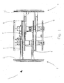
Fig. 1 gives a schematic view of the front side of the clamping device according to the invention; -
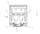
Fig. 2 gives a schematic view of the left side of the device; -
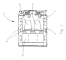
Fig. 3 gives a schematic view of the right side of the device; -
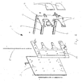
Fig. 4 is an axonometric view of the left side of the device. -
Number 1, with reference to the attached illustrations, indicates a clamping device that allows to hoist and move loads of whatever shape, and in particular with a basically prismatic form, composed of two vertical opposed plates 2 and 3 each coupled to two slidingelements horizontal guides 6 and 7 in a manner controlled by the user by specific controls (not illustrated because they are known). Said slidingelements jaw 8, 9 shaped in order to have threeseparate pressure elements grasping jaws 8, 9. Each graspingjaw 8, 9 exerts pressure on a respective graspingsegment segment - More specifically said horizontal
axis sliding elements fig. 1 ) in a transversal direction with respect to the front part of the vehicle, making movements in two opposite directions in a reciprocal approach or distancing motion and each graspingsegment - In a preferred embodiment, illustrated in
figure 1 , the graspingsegments - The packages to transport are therefore laterally retained between said plates which are provided with suitable anti-slip seals designed for the purpose and package grasping and retaining are ensured by the equal and contrasting thrust received from the pistons placed on
horizontal guides 6 and 7. - As a consequence to retain the packages the grasping
segments - It is therefore sufficient, to use the system described, to introduce between the open grasping
segments - The combination of the central position of sliding
elements more pressure elements segments - The grasping
segments - Said preload advantageously provides, in this innovation, a limited but effective elastic deformation capacity by said grasping
segments - The cavity of the
grasping elements - In a preferred embodiment illustrated in
figures 2 ,3 and4 each of said graspingjaws covering element reference number 19 infigure 4 , coupled to the front ends of saidpressure elements element segments segments - Thanks to the
coupling elements segments - In the example illustrated said
pressure elements grasping jaw 8, 9 like the fingers from the palm of a hand. - They have about equal dimensions and are preferably but not exclusively odd in number and can be, for example, three as in
figures 2 and3 . - The
pressure elements elements figures 2 and3 ). - In another possible embodiment the presence of at least one proportional valve or at least one mechanical valve or at least another similar device is advantageously provided and functions to give the pistons the mechanical control to move the plates.
- A technician in the sector may foresee several modifications and variations to what has been described and illustrated, obtaining solutions that are to be held to be included within the realm of protection of the invention which is further defined, in its specific characteristics, by the following claims.
Claims (9)
- Collecting and clamping device that allows to hoist and move one or more loads, composed of two vertical opposed plates (2,3) coupled to sliding elements (4,5) designed to slide on horizontal guides (6,7), said plates (2,3) each including a grasping jaw (8,9), each one comprising at least two separate pressure elements (10, 11) machined in a monolithic body spreading out frontally from each of said grasping jaws (8,9), being coupled to a grasping segment (12, 13) made of elastic material to which it exerts pressure, each of said segment (12, 13) being placed on the internal side of each jaw (8, 9), characterized by the fact that said grasping segments (12, 13) are preloaded so that they are elastically deformed and form a concave surface with respect to said loads.
- Collecting and clamping device according to claim 1, wherein each of said grasping jaws (8,9) is coupled and hinged to a jointed element (14,15), by connection and fastening means (19) at the front ends of said pressure elements (10,11) and said jointed element (14,15) is in contact with said grasping segments (12,13).
- Collecting and clamping device according to claim 2, wherein the dimension of the cavity of the grasping segments (12, 13) can be varied thanks to said coupling of said jointed elements (14, 15) to said grasping jaws (8,9).
- Collecting and clamping device according to claim 2 or 3, wherein in the pressure elements (10,11) a passing hole is obtained in which a pin (19) is inserted in order to connect the jointed elements (14,15) in which passing holes are obtained for the insertion of said pin (19).
- Collecting and clamping device according to one of the preceding claims, wherein said pressure elements (10,11) are covered and connected together by connection elements (16,16') and (17,17').
- Collecting and clamping device according to one of the preceding claims, wherein in each jaw (8, 9) said pressure elements (10, 11) are in an odd number.
- Collecting and clamping device according to one of the preceding claims, wherein said basically concave surface has vertical radii of curvature greater than or equal to the horizontal radii of curvature.
- Collecting and clamping device according to one of the preceding claims, wherein said concave surface has variable vertical radii of curvature and constant horizontal radii of curvature.
- Collecting and clamping device according to one of the preceding claims, wherein the sliding elements (4,5) are placed in a central position with respect to each plate (3,4).
Applications Claiming Priority (1)
| Application Number | Priority Date | Filing Date | Title |
|---|---|---|---|
| IT000031U ITVR20070031U1 (en) | 2007-05-30 | 2007-05-30 | COLLECTING AND TIGHTENING DEVICE FOR LOADS TO BE TRANSPORTED TO BE ASSOCIATED WITH FORKLIFT OR SIMILAR TROLLEYS. |
Publications (3)
| Publication Number | Publication Date |
|---|---|
| EP1997771A2 EP1997771A2 (en) | 2008-12-03 |
| EP1997771A3 EP1997771A3 (en) | 2009-05-13 |
| EP1997771B1 true EP1997771B1 (en) | 2011-03-16 |
Family
ID=39768970
Family Applications (1)
| Application Number | Title | Priority Date | Filing Date |
|---|---|---|---|
| EP08157360A Active EP1997771B1 (en) | 2007-05-30 | 2008-05-30 | Device for clamping loads for lift trucks |
Country Status (4)
| Country | Link |
|---|---|
| EP (1) | EP1997771B1 (en) |
| AT (1) | ATE501973T1 (en) |
| DE (1) | DE602008005514D1 (en) |
| IT (1) | ITVR20070031U1 (en) |
Cited By (2)
| Publication number | Priority date | Publication date | Assignee | Title |
|---|---|---|---|---|
| DE202013003227U1 (en) | 2012-04-09 | 2013-05-08 | Cascade Corporation | Cardboard clamping arm with adjustable swivel block |
| USD702412S1 (en) | 2012-04-09 | 2014-04-08 | Cascade Corporation | Carton clamp arm for a lift truck |
Families Citing this family (5)
| Publication number | Priority date | Publication date | Assignee | Title |
|---|---|---|---|---|
| ITVR20090181A1 (en) | 2009-10-29 | 2011-04-30 | Cascade Italia S R L | PREFERABLY HANDLING DEVICE FOR FORKLIFT TRUCKS |
| US10131525B2 (en) | 2014-10-30 | 2018-11-20 | Cascade Corporation | Pivoting load-bearing assembly with force sensor |
| US12024412B2 (en) | 2014-10-30 | 2024-07-02 | Cascade Corporation | Pivoting load-bearing assembly with force sensor |
| US10011468B2 (en) | 2014-10-30 | 2018-07-03 | Cascade Corporation | Pivoting load-bearing assembly with force sensor |
| CN106629503A (en) * | 2017-03-10 | 2017-05-10 | 合肥汉德贝尔属具科技有限公司 | Soft package clamp special for forklift |
Family Cites Families (4)
| Publication number | Priority date | Publication date | Assignee | Title |
|---|---|---|---|---|
| GB829369A (en) * | 1957-03-02 | 1960-03-02 | Samuel Edgar Rodman | Improvements in or relating to lifting trucks |
| BE759277A (en) * | 1969-11-24 | 1971-04-30 | Clark Equipment Co | CLAMPING EQUIPMENT FOR LIFT TRUCKS |
| ITVR20020065A1 (en) * | 2002-06-12 | 2003-12-12 | Roncari S R L | FORCES CONTROL AND COMMAND DEVICE FOR THE TIGHTENING OF LOADS TO BE TRANSPORTED BY LIFT TRUCKS OR SIMILAR. |
| US7412919B2 (en) * | 2004-08-04 | 2008-08-19 | Loron, Inc. | Hydraulic force control system for clamping assembly |
-
2007
- 2007-05-30 IT IT000031U patent/ITVR20070031U1/en unknown
-
2008
- 2008-05-30 DE DE602008005514T patent/DE602008005514D1/en active Active
- 2008-05-30 EP EP08157360A patent/EP1997771B1/en active Active
- 2008-05-30 AT AT08157360T patent/ATE501973T1/en not_active IP Right Cessation
Cited By (4)
| Publication number | Priority date | Publication date | Assignee | Title |
|---|---|---|---|---|
| DE202013003227U1 (en) | 2012-04-09 | 2013-05-08 | Cascade Corporation | Cardboard clamping arm with adjustable swivel block |
| US8517440B1 (en) | 2012-04-09 | 2013-08-27 | Cascade Corporation | Carton clamp arm with adjustable pivot block |
| USD702412S1 (en) | 2012-04-09 | 2014-04-08 | Cascade Corporation | Carton clamp arm for a lift truck |
| USRE46172E1 (en) | 2012-04-09 | 2016-10-04 | Cascade Corporation | Carton clamp arm with adjustable pivot block |
Also Published As
| Publication number | Publication date |
|---|---|
| ATE501973T1 (en) | 2011-04-15 |
| EP1997771A2 (en) | 2008-12-03 |
| DE602008005514D1 (en) | 2011-04-28 |
| ITVR20070031U1 (en) | 2008-11-30 |
| EP1997771A3 (en) | 2009-05-13 |
Similar Documents
| Publication | Publication Date | Title |
|---|---|---|
| EP1997771A2 (en) | Device for clamping loads for lift trucks | |
| US3328066A (en) | Pickup device for trash | |
| US5588688A (en) | Robotic grasping apparatus | |
| US4718816A (en) | Load handling attachment for vehicles | |
| ES2958622T3 (en) | pallet grab | |
| JP5792887B2 (en) | Carton clamp arm with adjustable swivel block | |
| US20130285401A1 (en) | Grabber | |
| US3433376A (en) | Combination facing for clamp device | |
| CA2132035A1 (en) | Load Transfer and Loading Device | |
| KR102526690B1 (en) | Article clip for folding machine, article clip assembly and folding machine article transfer method | |
| EP1371601B1 (en) | Apparatus to control and actuate the gripping forces for loads to be carried by means of lift trucks or the like | |
| JP5421930B2 (en) | Device for fixing or manipulating objects | |
| US2956700A (en) | Load clamp for industrial truck | |
| EP3694805B1 (en) | Grip and block system for a forklift truck and related forklift truck | |
| US5871242A (en) | Carton, box and bulk material lifting device | |
| CN108006028A (en) | Receiving clamp, assembly and bearing system, receiving clamp and working instrument assembly | |
| US5374033A (en) | Spreading or lifting device | |
| KR101805606B1 (en) | Gripper having enhanced Heat resistance, impact resistance and wear resistance | |
| US5873615A (en) | Grapple | |
| KR20160057614A (en) | structure for series connection of carts | |
| WO2017149461A1 (en) | Method for automatically picking metallic elements of elongated shape and picking device | |
| US6685248B2 (en) | Object engaging tool and method of manipulating object using same | |
| US20170089755A1 (en) | Weight loader | |
| JPS6236294A (en) | Lifting gear enabling clamping | |
| CN217323059U (en) | Clamp lifting appliance with anti-skidding structure |
Legal Events
| Date | Code | Title | Description |
|---|---|---|---|
| PUAI | Public reference made under article 153(3) epc to a published international application that has entered the european phase |
Free format text: ORIGINAL CODE: 0009012 |
|
| AK | Designated contracting states |
Kind code of ref document: A2 Designated state(s): AT BE BG CH CY CZ DE DK EE ES FI FR GB GR HR HU IE IS IT LI LT LU LV MC MT NL NO PL PT RO SE SI SK TR |
|
| AX | Request for extension of the european patent |
Extension state: AL BA MK RS |
|
| PUAL | Search report despatched |
Free format text: ORIGINAL CODE: 0009013 |
|
| AK | Designated contracting states |
Kind code of ref document: A3 Designated state(s): AT BE BG CH CY CZ DE DK EE ES FI FR GB GR HR HU IE IS IT LI LT LU LV MC MT NL NO PL PT RO SE SI SK TR |
|
| AX | Request for extension of the european patent |
Extension state: AL BA MK RS |
|
| 17P | Request for examination filed |
Effective date: 20091027 |
|
| 17Q | First examination report despatched |
Effective date: 20091202 |
|
| AKX | Designation fees paid |
Designated state(s): AT BE BG CH CY CZ DE DK EE ES FI FR GB GR HR HU IE IS IT LI LT LU LV MC MT NL NO PL PT RO SE SI SK TR |
|
| GRAP | Despatch of communication of intention to grant a patent |
Free format text: ORIGINAL CODE: EPIDOSNIGR1 |
|
| GRAS | Grant fee paid |
Free format text: ORIGINAL CODE: EPIDOSNIGR3 |
|
| GRAA | (expected) grant |
Free format text: ORIGINAL CODE: 0009210 |
|
| AK | Designated contracting states |
Kind code of ref document: B1 Designated state(s): AT BE BG CH CY CZ DE DK EE ES FI FR GB GR HR HU IE IS IT LI LT LU LV MC MT NL NO PL PT RO SE SI SK TR |
|
| REG | Reference to a national code |
Ref country code: GB Ref legal event code: FG4D |
|
| REG | Reference to a national code |
Ref country code: CH Ref legal event code: EP |
|
| REG | Reference to a national code |
Ref country code: IE Ref legal event code: FG4D |
|
| REF | Corresponds to: |
Ref document number: 602008005514 Country of ref document: DE Date of ref document: 20110428 Kind code of ref document: P |
|
| REG | Reference to a national code |
Ref country code: DE Ref legal event code: R096 Ref document number: 602008005514 Country of ref document: DE Effective date: 20110428 |
|
| REG | Reference to a national code |
Ref country code: NL Ref legal event code: VDEP Effective date: 20110316 |
|
| PG25 | Lapsed in a contracting state [announced via postgrant information from national office to epo] |
Ref country code: HR Free format text: LAPSE BECAUSE OF FAILURE TO SUBMIT A TRANSLATION OF THE DESCRIPTION OR TO PAY THE FEE WITHIN THE PRESCRIBED TIME-LIMIT Effective date: 20110316 Ref country code: NO Free format text: LAPSE BECAUSE OF FAILURE TO SUBMIT A TRANSLATION OF THE DESCRIPTION OR TO PAY THE FEE WITHIN THE PRESCRIBED TIME-LIMIT Effective date: 20110616 Ref country code: LV Free format text: LAPSE BECAUSE OF FAILURE TO SUBMIT A TRANSLATION OF THE DESCRIPTION OR TO PAY THE FEE WITHIN THE PRESCRIBED TIME-LIMIT Effective date: 20110316 Ref country code: ES Free format text: LAPSE BECAUSE OF FAILURE TO SUBMIT A TRANSLATION OF THE DESCRIPTION OR TO PAY THE FEE WITHIN THE PRESCRIBED TIME-LIMIT Effective date: 20110627 Ref country code: GR Free format text: LAPSE BECAUSE OF FAILURE TO SUBMIT A TRANSLATION OF THE DESCRIPTION OR TO PAY THE FEE WITHIN THE PRESCRIBED TIME-LIMIT Effective date: 20110617 Ref country code: SE Free format text: LAPSE BECAUSE OF FAILURE TO SUBMIT A TRANSLATION OF THE DESCRIPTION OR TO PAY THE FEE WITHIN THE PRESCRIBED TIME-LIMIT Effective date: 20110316 Ref country code: LT Free format text: LAPSE BECAUSE OF FAILURE TO SUBMIT A TRANSLATION OF THE DESCRIPTION OR TO PAY THE FEE WITHIN THE PRESCRIBED TIME-LIMIT Effective date: 20110316 |
|
| LTIE | Lt: invalidation of european patent or patent extension |
Effective date: 20110316 |
|
| PG25 | Lapsed in a contracting state [announced via postgrant information from national office to epo] |
Ref country code: FI Free format text: LAPSE BECAUSE OF FAILURE TO SUBMIT A TRANSLATION OF THE DESCRIPTION OR TO PAY THE FEE WITHIN THE PRESCRIBED TIME-LIMIT Effective date: 20110316 Ref country code: CY Free format text: LAPSE BECAUSE OF FAILURE TO SUBMIT A TRANSLATION OF THE DESCRIPTION OR TO PAY THE FEE WITHIN THE PRESCRIBED TIME-LIMIT Effective date: 20110316 Ref country code: SI Free format text: LAPSE BECAUSE OF FAILURE TO SUBMIT A TRANSLATION OF THE DESCRIPTION OR TO PAY THE FEE WITHIN THE PRESCRIBED TIME-LIMIT Effective date: 20110316 Ref country code: AT Free format text: LAPSE BECAUSE OF FAILURE TO SUBMIT A TRANSLATION OF THE DESCRIPTION OR TO PAY THE FEE WITHIN THE PRESCRIBED TIME-LIMIT Effective date: 20110316 Ref country code: BG Free format text: LAPSE BECAUSE OF FAILURE TO SUBMIT A TRANSLATION OF THE DESCRIPTION OR TO PAY THE FEE WITHIN THE PRESCRIBED TIME-LIMIT Effective date: 20110616 |
|
| PG25 | Lapsed in a contracting state [announced via postgrant information from national office to epo] |
Ref country code: BE Free format text: LAPSE BECAUSE OF FAILURE TO SUBMIT A TRANSLATION OF THE DESCRIPTION OR TO PAY THE FEE WITHIN THE PRESCRIBED TIME-LIMIT Effective date: 20110316 |
|
| PG25 | Lapsed in a contracting state [announced via postgrant information from national office to epo] |
Ref country code: PT Free format text: LAPSE BECAUSE OF FAILURE TO SUBMIT A TRANSLATION OF THE DESCRIPTION OR TO PAY THE FEE WITHIN THE PRESCRIBED TIME-LIMIT Effective date: 20110718 Ref country code: EE Free format text: LAPSE BECAUSE OF FAILURE TO SUBMIT A TRANSLATION OF THE DESCRIPTION OR TO PAY THE FEE WITHIN THE PRESCRIBED TIME-LIMIT Effective date: 20110316 |
|
| PG25 | Lapsed in a contracting state [announced via postgrant information from national office to epo] |
Ref country code: CZ Free format text: LAPSE BECAUSE OF FAILURE TO SUBMIT A TRANSLATION OF THE DESCRIPTION OR TO PAY THE FEE WITHIN THE PRESCRIBED TIME-LIMIT Effective date: 20110316 Ref country code: IS Free format text: LAPSE BECAUSE OF FAILURE TO SUBMIT A TRANSLATION OF THE DESCRIPTION OR TO PAY THE FEE WITHIN THE PRESCRIBED TIME-LIMIT Effective date: 20110716 Ref country code: RO Free format text: LAPSE BECAUSE OF FAILURE TO SUBMIT A TRANSLATION OF THE DESCRIPTION OR TO PAY THE FEE WITHIN THE PRESCRIBED TIME-LIMIT Effective date: 20110316 Ref country code: SK Free format text: LAPSE BECAUSE OF FAILURE TO SUBMIT A TRANSLATION OF THE DESCRIPTION OR TO PAY THE FEE WITHIN THE PRESCRIBED TIME-LIMIT Effective date: 20110316 |
|
| PG25 | Lapsed in a contracting state [announced via postgrant information from national office to epo] |
Ref country code: MC Free format text: LAPSE BECAUSE OF NON-PAYMENT OF DUE FEES Effective date: 20110531 Ref country code: NL Free format text: LAPSE BECAUSE OF FAILURE TO SUBMIT A TRANSLATION OF THE DESCRIPTION OR TO PAY THE FEE WITHIN THE PRESCRIBED TIME-LIMIT Effective date: 20110316 Ref country code: MT Free format text: LAPSE BECAUSE OF FAILURE TO SUBMIT A TRANSLATION OF THE DESCRIPTION OR TO PAY THE FEE WITHIN THE PRESCRIBED TIME-LIMIT Effective date: 20110316 |
|
| PLBE | No opposition filed within time limit |
Free format text: ORIGINAL CODE: 0009261 |
|
| STAA | Information on the status of an ep patent application or granted ep patent |
Free format text: STATUS: NO OPPOSITION FILED WITHIN TIME LIMIT |
|
| 26N | No opposition filed |
Effective date: 20111219 |
|
| PG25 | Lapsed in a contracting state [announced via postgrant information from national office to epo] |
Ref country code: DK Free format text: LAPSE BECAUSE OF FAILURE TO SUBMIT A TRANSLATION OF THE DESCRIPTION OR TO PAY THE FEE WITHIN THE PRESCRIBED TIME-LIMIT Effective date: 20110316 Ref country code: PL Free format text: LAPSE BECAUSE OF FAILURE TO SUBMIT A TRANSLATION OF THE DESCRIPTION OR TO PAY THE FEE WITHIN THE PRESCRIBED TIME-LIMIT Effective date: 20110316 |
|
| REG | Reference to a national code |
Ref country code: IE Ref legal event code: MM4A |
|
| REG | Reference to a national code |
Ref country code: DE Ref legal event code: R097 Ref document number: 602008005514 Country of ref document: DE Effective date: 20111219 |
|
| PG25 | Lapsed in a contracting state [announced via postgrant information from national office to epo] |
Ref country code: IE Free format text: LAPSE BECAUSE OF NON-PAYMENT OF DUE FEES Effective date: 20110530 |
|
| REG | Reference to a national code |
Ref country code: CH Ref legal event code: PL |
|
| PG25 | Lapsed in a contracting state [announced via postgrant information from national office to epo] |
Ref country code: CH Free format text: LAPSE BECAUSE OF NON-PAYMENT OF DUE FEES Effective date: 20120531 Ref country code: LI Free format text: LAPSE BECAUSE OF NON-PAYMENT OF DUE FEES Effective date: 20120531 |
|
| PG25 | Lapsed in a contracting state [announced via postgrant information from national office to epo] |
Ref country code: LU Free format text: LAPSE BECAUSE OF NON-PAYMENT OF DUE FEES Effective date: 20110530 |
|
| PG25 | Lapsed in a contracting state [announced via postgrant information from national office to epo] |
Ref country code: HU Free format text: LAPSE BECAUSE OF FAILURE TO SUBMIT A TRANSLATION OF THE DESCRIPTION OR TO PAY THE FEE WITHIN THE PRESCRIBED TIME-LIMIT Effective date: 20110316 |
|
| REG | Reference to a national code |
Ref country code: FR Ref legal event code: PLFP Year of fee payment: 9 |
|
| REG | Reference to a national code |
Ref country code: FR Ref legal event code: PLFP Year of fee payment: 10 |
|
| REG | Reference to a national code |
Ref country code: FR Ref legal event code: PLFP Year of fee payment: 11 |
|
| PGFP | Annual fee paid to national office [announced via postgrant information from national office to epo] |
Ref country code: DE Payment date: 20250529 Year of fee payment: 18 |
|
| PGFP | Annual fee paid to national office [announced via postgrant information from national office to epo] |
Ref country code: GB Payment date: 20250527 Year of fee payment: 18 |
|
| PGFP | Annual fee paid to national office [announced via postgrant information from national office to epo] |
Ref country code: IT Payment date: 20250521 Year of fee payment: 18 |
|
| PGFP | Annual fee paid to national office [announced via postgrant information from national office to epo] |
Ref country code: FR Payment date: 20250526 Year of fee payment: 18 |
|
| PGFP | Annual fee paid to national office [announced via postgrant information from national office to epo] |
Ref country code: TR Payment date: 20250515 Year of fee payment: 18 |
|
| REG | Reference to a national code |
Ref country code: GB Ref legal event code: 732E Free format text: REGISTERED BETWEEN 20251211 AND 20251217 |
|
| REG | Reference to a national code |
Ref country code: DE Ref legal event code: R081 Ref document number: 602008005514 Country of ref document: DE Owner name: CASCADE CORPORATION, FAIRVIEW, US Free format text: FORMER OWNER: CASCADE ITALIA S.R.L., VAGO DI LAVAGNO, IT |